EP1936466B1 - Multi-axis trim processing - Google Patents
Multi-axis trim processing Download PDFInfo
- Publication number
- EP1936466B1 EP1936466B1 EP07254897A EP07254897A EP1936466B1 EP 1936466 B1 EP1936466 B1 EP 1936466B1 EP 07254897 A EP07254897 A EP 07254897A EP 07254897 A EP07254897 A EP 07254897A EP 1936466 B1 EP1936466 B1 EP 1936466B1
- Authority
- EP
- European Patent Office
- Prior art keywords
- trim
- values
- acceleration
- recited
- variables
- Prior art date
- Legal status (The legal status is an assumption and is not a legal conclusion. Google has not performed a legal analysis and makes no representation as to the accuracy of the status listed.)
- Active
Links
- 238000000034 method Methods 0.000 claims abstract description 40
- 230000001133 acceleration Effects 0.000 claims description 87
- 239000011159 matrix material Substances 0.000 claims description 17
- RZVHIXYEVGDQDX-UHFFFAOYSA-N 9,10-anthraquinone Chemical compound C1=CC=C2C(=O)C3=CC=CC=C3C(=O)C2=C1 RZVHIXYEVGDQDX-UHFFFAOYSA-N 0.000 claims description 12
- 238000013213 extrapolation Methods 0.000 claims description 8
- 230000003416 augmentation Effects 0.000 claims description 6
- 230000008878 coupling Effects 0.000 claims description 5
- 238000010168 coupling process Methods 0.000 claims description 5
- 238000005859 coupling reaction Methods 0.000 claims description 5
- 230000008030 elimination Effects 0.000 claims description 4
- 238000003379 elimination reaction Methods 0.000 claims description 4
- 238000010845 search algorithm Methods 0.000 claims description 4
- 238000010276 construction Methods 0.000 claims 2
- 230000008569 process Effects 0.000 description 16
- 230000005484 gravity Effects 0.000 description 4
- 230000003190 augmentative effect Effects 0.000 description 3
- 230000000694 effects Effects 0.000 description 3
- 238000009966 trimming Methods 0.000 description 3
- 238000010586 diagram Methods 0.000 description 2
- 238000011156 evaluation Methods 0.000 description 2
- 239000000446 fuel Substances 0.000 description 2
- 238000012546 transfer Methods 0.000 description 2
- 235000015842 Hesperis Nutrition 0.000 description 1
- 235000012633 Iberis amara Nutrition 0.000 description 1
- 230000008859 change Effects 0.000 description 1
- 230000007812 deficiency Effects 0.000 description 1
- 238000011161 development Methods 0.000 description 1
- 239000002828 fuel tank Substances 0.000 description 1
- 238000012986 modification Methods 0.000 description 1
- 230000004048 modification Effects 0.000 description 1
- 238000011867 re-evaluation Methods 0.000 description 1
- 238000005096 rolling process Methods 0.000 description 1
- 238000004088 simulation Methods 0.000 description 1
- 238000012549 training Methods 0.000 description 1
Images


Classifications
-
- G—PHYSICS
- G05—CONTROLLING; REGULATING
- G05D—SYSTEMS FOR CONTROLLING OR REGULATING NON-ELECTRIC VARIABLES
- G05D1/00—Control of position, course or altitude of land, water, air, or space vehicles, e.g. automatic pilot
- G05D1/08—Control of attitude, i.e. control of roll, pitch, or yaw
- G05D1/0808—Control of attitude, i.e. control of roll, pitch, or yaw specially adapted for aircraft
Definitions
- This disclosure relates generally to aeronautics and, more particularly, to a method and system for determining aircraft trim solutions substantially simultaneously in six degrees of freedom.
- the flight control surfaces and engine thrust of an aircraft are trimmed to maintain a desired flight condition described by altitude, speed, attitude and heading of the aircraft, as well as to effect some desired changes in altitude, speed, attitude and heading.
- the flight control surfaces are trimmed to provide straight and level flight.
- Trim may be used to compensate for such factors as imbalances or shifts in load (people, cargo, and fuel) and for winds that would otherwise undesirably alter the altitude, speed, attitude or heading of the aircraft, as well as for thrust asymmetry due to engine failure.
- trim may be used to compensate for an imbalanced in the weight distribution of cargo that would otherwise cause the aircraft to roll undesirably to one side.
- trim may be used to compensate for a cross wind that would otherwise cause the aircraft to yaw undesirably away from its desired heading.
- ailerons and spoilers may be moved to a position that returns the aircraft to level flight.
- a rudder may be moved so as to maintain the desired heading.
- control surfaces on smaller aircraft may be positioned manually, such as by using pilot operated mechanical systems, e.g., cables and pulleys.
- pilot operated mechanical systems e.g., cables and pulleys.
- larger aircraft generally require electric motor or hydraulically operated control surfaces.
- an automated trim system attempts to maintain desired aircraft altitude, speed, attitude and heading with minimal pilot intervention.
- Flight simulators are important tools that are extensively used by the airline industry and the military for pilot training and disaster simulation and by aircraft manufacturers for aircraft development.
- One of the most important aspects of flight simulators is the trim system and method.
- Trim systems determine trim variables such as angles of attack and sideslip, flight path angle, column input, pedal input, wheel input, and throttle position to drive both angular accelerations (pitch, roll and yaw) and point mass linear accelerations (tangential acceleration and centripetal acceleration) to target values (which are typically zero).
- the contemporary trim process is a single-axis process. That is, the trim variables are determined one at a time to drive a single acceleration corresponding to a single trim variable. For example, sideslip angle may be used to drive yaw acceleration to zero (thereby maintaining a desired heading). After yaw acceleration has been driven to zero, then a different trim variable may be used to drive its corresponding acceleration to zero, and so on.
- One of the flight boundaries is the lowest speed at which an aircraft can remain trimmed with both pedal and wheel input at their mechanical limits.
- the wheel becomes ineffective in controlling rolling moment.
- Sideslip angle can still effectively control the accelerations in both roll and yaw axes.
- the contemporary trim systems often fail to find the trim solutions at this boundary.
- trim system that generally simultaneously determines values for trim variables in a plurality of different degrees of freedom so as to substantially mitigate the iterative aspects of contemporary trim systems and thereby enhance efficiency and provide a more robust trim system.
- US 2003/0106958 describes a trim augmentation system for a rotary wing aircraft having a trim augmentation algorithm that provides augmentation of the rotor trim via on-axis stick input and automatic cross-axis trim transfer as a function of the commanded yaw rate.
- US 2005/0051666 describes an aircraft with active center of gravity control where a controller can transfer fuel among the plurality of fuel tanks and adjust the aircraft center of gravity to reduce trim drag.
- a method for providing trim comprises generally simultaneously determining values for a plurality of trim variables in a plurality of degrees of freedom.
- a system for providing trim comprises a processor configured to generally simultaneously determine values for a plurality of trim variables in a plurality of degrees of freedom.
- a system for providing trim comprises means for generally simultaneously determining values for a plurality of trim variables in a plurality of degrees of freedom.
- One or more embodiments provide a method and system for providing trim that substantially mitigates the iterative aspects of contemporary trim system and thereby enhances efficiency and provides a more robust trim system.
- An example of an embodiment comprises a method for providing trim wherein a plurality of trim solutions are simultaneously determined in a plurality of degrees of freedom.
- the trim solutions may be generally simultaneously determined in six degrees of freedom.
- the trim solution may be determined for both target linear and angular accelerations.
- At least one embodiment is suitable for determining trim solutions for aircraft having nonlinear aerodynamics. Multi-axis coupling may be considered in determining the trim solutions. At least one embodiment is suitable for determining trim solutions for an aircraft having a flight control augmentation system.
- the term "generally simultaneously” is defined to include determining a plurality of trim variables in a manner that facilitates driving a plurality of corresponding accelerations to their target values at approximately the same time.
- One acceleration does not have to be driven to its target value before the next acceleration is driven to its target value. This may be accomplished, for example, by solving for a plurality of unknowns (trim values) in a plurality of formulas (which characterize the relationship of the trim values to aircraft parameters and to each other).
- trim values are defined serially, i.e., the value of one trim variable is determined at a time in a manner that necessitates the recursive recalculation of these variables. That is, a first trim solution is determined (such as by driving a corresponding acceleration to approximately zero), then a second trim solution is determined. After the acceleration corresponding to the second trim solution has been corrected (again, such as by driving the acceleration to zero), then the first trim solution is typically no longer valid and must be solved for again. This process continues recursively until all of the trim values are within desired tolerances.
- trim values generally simultaneously By determining the trim values generally simultaneously, as is done according to one or more embodiments, the need for such recursion is substantially mitigated or eliminated. Moreover, a plurality (such as all) of the trim values may be determined generally simultaneously and a corresponding plurality of accelerations may be driven to target values generally simultaneously. In this manner, a more efficient and more robust trim system is provided.
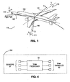
- Figure 1 shows an aircraft 100 with the linear and angular accelerations labeled.
- a x is the tangential acceleration 102
- ay is the lateral centripetal acceleration 104
- a z is the vertical centripetal acceleration 106
- ⁇ is the roll acceleration 108
- q ⁇ is the pitch acceleration 110
- ⁇ is the yaw acceleration 112, comprising a plurality of degrees of freedom 114.
- One or more of angle of attack, angle of sideslip, aircraft speed, flight path angle, bank angle, drift angle, pitch/roll/yaw control input, engine throttle input, weight, center of gravity, as well as any other desired parameters may be used to drive one or more of tangential acceleration, lateral centripetal acceleration, vertical centripetal acceleration, roll acceleration, pitch acceleration, and yaw acceleration to their target values.
- Figures 2A and 2B show an overview of the multi-axis trim process according to an example of an embodiment.
- initialization of the multi-axis trim process comprises blocks 204 thru 208, which are discussed below.
- the acceleration residual tolerances are set for trim, as indicated in block 204.
- the differences between the aircraft acceleration components and their targets have to fall within the acceleration residual tolerances in order to achieve a successful trim.
- the trim variables are initialized, as indicated in block 205. To initialize the trim variables, they are typically set values that are representative of the current states of the aircraft 100. They can also be a set of nominal values selected according to types of trim variables and trim objectives.
- the trim variables are determined, as indicated in block 206 based on trim objectives.
- the values of trim variables may be determined by solving a plurality of equations for a plurality of variables, such as by using matrix algebra.
- the constants of the equations may represent the initial trim values and/or parameters that characterize how the accelerations relate to the trim values.
- the variables of the equations represent the desired solutions or trim values.
- the equations may be solved to determine values for the trim variables according to well known matrix algebra rules.
- trim variables may be selected and determined from such parameters as angles of attack and slideslip, aircraft speed, flight path angle, bank angle, drift angle, pitch control input, roll control input, yaw control input, engine throttle input, aircraft weight, and center of gravity, for example.
- the components of linear and angular acceleration that affect trim are determined and desired accelerations targets for these values are set, as indicated in block 207.
- the components of linear and angular acceleration are those actually being experienced by the aircraft at the time that the trim values are being determined.
- the acceleration targets are the desired values for these accelerations and result in the aircraft having the desired flight conditions. Typically, the acceleration targets will be zero. Zero acceleration occurs when the aircraft is flying level and the heading is not changing.
- Non-zero acceleration targets are also possible. Non-zero accelerations may occur, for example, when the aircraft is being banked so as to change the heading thereof.
- the bounds for the trim variables are determined, as indicated in block 208.
- the bounds may include the physical limitations of the trim system.
- the bounds may be defined, at least in part, by the mechanical limits (extent of travel) of the pilot control devices or control surfaces.
- the bounds may also be determined by the aircraft aerodynamic capabilities and structure limits such as stalling angles of attack and maximum operation speed, etc.
- Aircraft dynamic models which may include couplings, are used as indicated in block 209 to provide force and moment information to a Newton's second law algorithm, as indicated in block 210.
- the output of the Newton's second law algorithm is provided to an acceleration algorithm, as indicated by block 211.
- the acceleration algorithm provides accelerations that result from the application of aircraft dynamic models and Newton's second law to the initial values of the trim variables, the border or inbound values of the trim variables, and the updated values of the trim variables.
- the acceleration residuals are determined by the differences between these accelerations and their corresponding targets. These acceleration residuals are provided to a multi-axis search algorithm, as indicated by block 300 and a multi-axis extrapolation, as indicated by block 400 and discussed in further detail below.
- the acceleration residual tolerances from block 204, the updated acceleration residuals, and the extrapolated acceleration residuals are provided to the multi-axis search algorithm for updating and determining values for the trim variables, as indicated by block 300 and discussed in further detail below.
- Figure 3 shows the multi-axis search process 300 of Figures 2A and 2B in further detail. This process involves constructing the initial Jacobian matrix and revising the Jacobian matrix using Boyden update, as discussed below.
- the acceleration residuals are used to determine the updated trim variables according to well-known principles.
- the trim variable increment may be determined by using Gaussian elimination.
- an iteration counter is initialized as indicated by block 301 and incremented for each iteration as indicated by block 302.
- the acceleration residual norm is valuated, as indicated in block 303.
- a reduced norm between trim iterations may indicate a converging process in general.
- an initial Jacobian matrix is constructed as indicated in block 304.
- the acceleration residual norm is updated once at the beginning the iteration and is updated again using the results of each line search with adjustment of trim variable increment step size, as indicated in block 306.
- This process comprises re-evaluation of acceleration residuals at revised trim values due to their increment step size adjustment until the updated norm is less than the norm from the previous iteration.
- the acceleration increment is computed and the Jacobian matrix is revised using Boyden update, as indicated in block 307.
- Trim variable increments are determined using pivot Gaussian elimination, as indicated in block 308. This is the well-known matrix algebra process for determining a plurality of unknown values from a plurality of formulae.
- the Jacobian matrix, acceleration increment, and acceleration norm are saved, as indicated in block 309, for revising the Jacobian matrix in the next iteration.
- the trim variables are updated as indicated in block 310.
- Figure 4 shows the multi-axis extrapolation 400 of Figures 2A and 2B in detail.
- the axes along which trim variables are out of bounds are determined, as indicated in block 401.
- Bounded trim variables are defined by setting out-of-bounds variables at their bounds, as indicated in block 402. Acceleration residuals evaluation is requested at the bounded trim variables, as indicated in block 403.
- Perturbed trim variables are created by moving bounded trim variables inward, as indicated by block 405. Acceleration residual evaluation at the perturbed trim variables is requested, as indicated in block 406. The slopes of all acceleration residuals are computed using finite difference at the bounded and perturbed variables, as indicated by block 407. Linear extrapolation is performed along the identified axis using the slopes of all acceleration residuals, as indicated in block 408.
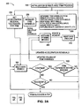
- FIG. 5 shows a block diagram of a trim system, according to an example of an embodiment.
- a plurality of sensors 51 provide outputs to a trim processor 50.
- Trim processor 50 controls the position of trim variables 52.
- Sensors 51 may comprise any sensors or other devices that provide information that may be used by trim processor 50 to determine trim values.
- sensors 51 may comprise sensor that provide information representative of such parameters as current body components of linear and angular accelerations of the aircraft, aerodynamic state, inertial position, and desired flight conditions described by altitude, speed, attitude and heading of the aircraft.
- Trim processor 50 may be a dedicated processor or may be a generally purpose computer. Trim processor may comprise one or more algorithms that are run on a computer that performs a variety of other, non-related tasks.
- Trim variables 52 may comprise main flight control surfaces, and the devices required to effect their movement (such as drive circuitry, electric motors, hydraulic pumps and motors). Trim processor 50, sensors 51, trim variables 52, can be part of a flight control augmentation system 500.
- one or more embodiments of the present provide a method and system for trimming and aircraft or other vehicle wherein the undesirable iterative aspects of contemporary trim systems are mitigated or eliminated. A more efficient and more robust trim system is thus provided.
Abstract
Description
- This disclosure relates generally to aeronautics and, more particularly, to a method and system for determining aircraft trim solutions substantially simultaneously in six degrees of freedom.
- The flight control surfaces and engine thrust of an aircraft are trimmed to maintain a desired flight condition described by altitude, speed, attitude and heading of the aircraft, as well as to effect some desired changes in altitude, speed, attitude and heading. Typically, the flight control surfaces are trimmed to provide straight and level flight.
- Trim may be used to compensate for such factors as imbalances or shifts in load (people, cargo, and fuel) and for winds that would otherwise undesirably alter the altitude, speed, attitude or heading of the aircraft, as well as for thrust asymmetry due to engine failure. For example, trim may be used to compensate for an imbalanced in the weight distribution of cargo that would otherwise cause the aircraft to roll undesirably to one side. Similarly, trim may be used to compensate for a cross wind that would otherwise cause the aircraft to yaw undesirably away from its desired heading.
- More particularly, when the aircraft is tending to roll to one side, ailerons and spoilers may be moved to a position that returns the aircraft to level flight. Similarly, if the aircraft is being blown off course, a rudder may be moved so as to maintain the desired heading.
- The control surfaces on smaller aircraft may be positioned manually, such as by using pilot operated mechanical systems, e.g., cables and pulleys. However, larger aircraft generally require electric motor or hydraulically operated control surfaces. On some aircraft, such as those with augmented (fly-by-wire) flight control systems, an automated trim system attempts to maintain desired aircraft altitude, speed, attitude and heading with minimal pilot intervention.
- Flight simulators are important tools that are extensively used by the airline industry and the military for pilot training and disaster simulation and by aircraft manufacturers for aircraft development. One of the most important aspects of flight simulators is the trim system and method.
- Although contemporary trim systems have proven generally useful for their intended purpose, such contemporary systems do suffer from inherent deficiencies that may detract from their utility and desirability. This is particularly true for modern aircraft that have highly nonlinear and highly coupled dynamics, or flight control systems that are augmented. This may also be true when such system follows the p-beta control law, which introduces highly augmented systems and significant system couplings between roll/yaw control and roll/yaw motion. As a result certain trim variables have switched their influences on aircraft motion from one axis to another axis.
- Trim systems determine trim variables such as angles of attack and sideslip, flight path angle, column input, pedal input, wheel input, and throttle position to drive both angular accelerations (pitch, roll and yaw) and point mass linear accelerations (tangential acceleration and centripetal acceleration) to target values (which are typically zero).
- However, the contemporary trim process is a single-axis process. That is, the trim variables are determined one at a time to drive a single acceleration corresponding to a single trim variable. For example, sideslip angle may be used to drive yaw acceleration to zero (thereby maintaining a desired heading). After yaw acceleration has been driven to zero, then a different trim variable may be used to drive its corresponding acceleration to zero, and so on.
- In this manner, contemporary trim systems solve for one trim variable by driving one acceleration to its target value at a time. After the trim system determines a trim solution for a first axis or acceleration, then the trim system moves on to a second axis and thus trims the second axis using a different trim variable. However, once trim is achieved along the second axis, the previously trimmed acceleration along the first axis typically becomes untrimmed. Thus, the first axis must be re-trimmed.
- The previously trimmed acceleration along the first axis typically becomes untrimmed after trim is achieved along the second axis because of strong couplings of the dynamic systems involved. This undesirable effect necessitates iterative trimming, which is inherently inefficient. That is, each degree of freedom must be repeatedly re-trimmed until all degrees of freedom are within desired tolerances. Such iterative trimming is not desirably robust and often fails to produce a trim solution when the aircraft is near the boundaries of the flight envelope and flight control limits.
- One of the flight boundaries is the lowest speed at which an aircraft can remain trimmed with both pedal and wheel input at their mechanical limits. When aircraft is nearing this speed limit at maximum pedal input, the wheel becomes ineffective in controlling rolling moment. Sideslip angle can still effectively control the accelerations in both roll and yaw axes. The contemporary trim systems often fail to find the trim solutions at this boundary.
- Further, although the p-beta control laws of some modern aircraft eliminate the lateral acceleration dependency on bank angle, they add a yaw acceleration dependency on the bank angle. This new acceleration dependency shift makes contemporary single axis trim process ineffective.
- As a result, there is a need for a trim system that generally simultaneously determines values for trim variables in a plurality of different degrees of freedom so as to substantially mitigate the iterative aspects of contemporary trim systems and thereby enhance efficiency and provide a more robust trim system.
- These objectives are achieved by the method of
claim 1 and the system of claim 8. -
US 2003/0106958 describes a trim augmentation system for a rotary wing aircraft having a trim augmentation algorithm that provides augmentation of the rotor trim via on-axis stick input and automatic cross-axis trim transfer as a function of the commanded yaw rate. -
US 2005/0051666 describes an aircraft with active center of gravity control where a controller can transfer fuel among the plurality of fuel tanks and adjust the aircraft center of gravity to reduce trim drag. - Systems and methods are disclosed herein to provide trim for a vehicle, such as an aircraft. In accordance with an example of an embodiment, a method for providing trim comprises generally simultaneously determining values for a plurality of trim variables in a plurality of degrees of freedom.
- According to an example of an embodiment, a system for providing trim comprises a processor configured to generally simultaneously determine values for a plurality of trim variables in a plurality of degrees of freedom.
- According to an example of an embodiment, a system for providing trim comprises means for generally simultaneously determining values for a plurality of trim variables in a plurality of degrees of freedom.
- One or more embodiments provide a method and system for providing trim that substantially mitigates the iterative aspects of contemporary trim system and thereby enhances efficiency and provides a more robust trim system.
- A more complete understanding of the embodiments will be afforded to those skilled in the art, as well as a realization of additional advantages thereof, by a consideration of the following detailed description of one or more embodiments. Reference will be made to the appended sheets of drawings that will first be described briefly.
-
-
Figure 1 shows an aircraft and indicates the accelerations that may be controlled according to an example of an embodiment; -
Figures 2A and2B show a flow chart of a multi-axis trim process according to an example of an embodiment of the present; -
Figure 3 shows a flow chart of the search process ofFigures 2A and2B ; -
Figure 4 shows a flow chart of the extrapolation process ofFigures 2A and2B ; and -
Figure 5 shows a block diagram of a trim system, according to an example of an embodiment. - Embodiments and their advantages are best understood by referring to the detailed description that follows. It should be appreciated that like reference numerals are used to identify like elements illustrated in one or more of the figures.
- An example of an embodiment comprises a method for providing trim wherein a plurality of trim solutions are simultaneously determined in a plurality of degrees of freedom. For example, the trim solutions may be generally simultaneously determined in six degrees of freedom. The trim solution may be determined for both target linear and angular accelerations.
- At least one embodiment is suitable for determining trim solutions for aircraft having nonlinear aerodynamics. Multi-axis coupling may be considered in determining the trim solutions. At least one embodiment is suitable for determining trim solutions for an aircraft having a flight control augmentation system.
- As used herein, the term "generally simultaneously" is defined to include determining a plurality of trim variables in a manner that facilitates driving a plurality of corresponding accelerations to their target values at approximately the same time. One acceleration does not have to be driven to its target value before the next acceleration is driven to its target value. This may be accomplished, for example, by solving for a plurality of unknowns (trim values) in a plurality of formulas (which characterize the relationship of the trim values to aircraft parameters and to each other).
- This is opposed to the contemporary method described above, wherein trim values are defined serially, i.e., the value of one trim variable is determined at a time in a manner that necessitates the recursive recalculation of these variables. That is, a first trim solution is determined (such as by driving a corresponding acceleration to approximately zero), then a second trim solution is determined. After the acceleration corresponding to the second trim solution has been corrected (again, such as by driving the acceleration to zero), then the first trim solution is typically no longer valid and must be solved for again. This process continues recursively until all of the trim values are within desired tolerances.
- By determining the trim values generally simultaneously, as is done according to one or more embodiments, the need for such recursion is substantially mitigated or eliminated. Moreover, a plurality (such as all) of the trim values may be determined generally simultaneously and a corresponding plurality of accelerations may be driven to target values generally simultaneously. In this manner, a more efficient and more robust trim system is provided.
-
Figure 1 shows anaircraft 100 with the linear and angular accelerations labeled. In this manner, ax is thetangential acceleration 102, ay is the lateralcentripetal acceleration 104, az is the verticalcentripetal acceleration 106, ṗ is theroll acceleration 108, q̇ is thepitch acceleration 110, and ṙ is theyaw acceleration 112, comprising a plurality of degrees offreedom 114. - One or more of angle of attack, angle of sideslip, aircraft speed, flight path angle, bank angle, drift angle, pitch/roll/yaw control input, engine throttle input, weight, center of gravity, as well as any other desired parameters may be used to drive one or more of tangential acceleration, lateral centripetal acceleration, vertical centripetal acceleration, roll acceleration, pitch acceleration, and yaw acceleration to their target values.
-
Figures 2A and2B show an overview of the multi-axis trim process according to an example of an embodiment. According to this embodiment, initialization of the multi-axis trim process, as indicated byblock 203, comprisesblocks 204 thru 208, which are discussed below. - The acceleration residual tolerances are set for trim, as indicated in
block 204. The differences between the aircraft acceleration components and their targets have to fall within the acceleration residual tolerances in order to achieve a successful trim. - The trim variables are initialized, as indicated in
block 205. To initialize the trim variables, they are typically set values that are representative of the current states of theaircraft 100. They can also be a set of nominal values selected according to types of trim variables and trim objectives. - The trim variables are determined, as indicated in
block 206 based on trim objectives. The values of trim variables may be determined by solving a plurality of equations for a plurality of variables, such as by using matrix algebra. The constants of the equations may represent the initial trim values and/or parameters that characterize how the accelerations relate to the trim values. The variables of the equations represent the desired solutions or trim values. The equations may be solved to determine values for the trim variables according to well known matrix algebra rules. - Depending on trim objectives the trim variables may be selected and determined from such parameters as angles of attack and slideslip, aircraft speed, flight path angle, bank angle, drift angle, pitch control input, roll control input, yaw control input, engine throttle input, aircraft weight, and center of gravity, for example.
- The components of linear and angular acceleration that affect trim are determined and desired accelerations targets for these values are set, as indicated in
block 207. The components of linear and angular acceleration are those actually being experienced by the aircraft at the time that the trim values are being determined. - The acceleration targets are the desired values for these accelerations and result in the aircraft having the desired flight conditions. Typically, the acceleration targets will be zero. Zero acceleration occurs when the aircraft is flying level and the heading is not changing.
- However, non-zero acceleration targets are also possible. Non-zero accelerations may occur, for example, when the aircraft is being banked so as to change the heading thereof.
- The bounds for the trim variables are determined, as indicated in
block 208. The bounds may include the physical limitations of the trim system. For example, the bounds may be defined, at least in part, by the mechanical limits (extent of travel) of the pilot control devices or control surfaces. The bounds may also be determined by the aircraft aerodynamic capabilities and structure limits such as stalling angles of attack and maximum operation speed, etc. - Aircraft dynamic models, which may include couplings, are used as indicated in
block 209 to provide force and moment information to a Newton's second law algorithm, as indicated inblock 210. The output of the Newton's second law algorithm is provided to an acceleration algorithm, as indicated byblock 211. The acceleration algorithm provides accelerations that result from the application of aircraft dynamic models and Newton's second law to the initial values of the trim variables, the border or inbound values of the trim variables, and the updated values of the trim variables. - The acceleration residuals are determined by the differences between these accelerations and their corresponding targets. These acceleration residuals are provided to a multi-axis search algorithm, as indicated by
block 300 and a multi-axis extrapolation, as indicated byblock 400 and discussed in further detail below. - The acceleration residual tolerances from
block 204, the updated acceleration residuals, and the extrapolated acceleration residuals are provided to the multi-axis search algorithm for updating and determining values for the trim variables, as indicated byblock 300 and discussed in further detail below. -
Figure 3 shows themulti-axis search process 300 ofFigures 2A and2B in further detail. This process involves constructing the initial Jacobian matrix and revising the Jacobian matrix using Boyden update, as discussed below. - The acceleration residuals are used to determine the updated trim variables according to well-known principles. The trim variable increment may be determined by using Gaussian elimination.
- More particularly, an iteration counter is initialized as indicated by block 301 and incremented for each iteration as indicated by
block 302. - The acceleration residual norm is valuated, as indicated in
block 303. The acceleration residual norm is defined as the square root of sum of the normalized square of all selected acceleration residuals. If all six linear and angular acceleration components are to be trimmed, a norm N can be
- A reduced norm between trim iterations may indicate a converging process in general.
- If the iteration counter is equal to one, an initial Jacobian matrix is constructed as indicated in
block 304. For illustration purpose without loss of generality, angle of attack α, sideslip angle β, flight path angle γ, pilot column input δc, pedal input δp and wheel input δw are selected as trim variables to trim all six linear and angular acceleration components


- The initial Jacobian matrix is constructed using finite difference at the initial values of the trim variables, as follows:

- As indicated in
block 305 if the iteration counter is not equal to one, the acceleration residual norm is updated once at the beginning the iteration and is updated again using the results of each line search with adjustment of trim variable increment step size, as indicated inblock 306. This process comprises re-evaluation of acceleration residuals at revised trim values due to their increment step size adjustment until the updated norm is less than the norm from the previous iteration. - The acceleration increment is computed and the Jacobian matrix is revised using Boyden update, as indicated in
block 307. A Boyden update is performed by adding an incremental matrix to the Jacobian matrix from previous iteration, Ji as such,


- Trim variable increments are determined using pivot Gaussian elimination, as indicated in
block 308. This is the well-known matrix algebra process for determining a plurality of unknown values from a plurality of formulae. - The Jacobian matrix, acceleration increment, and acceleration norm are saved, as indicated in
block 309, for revising the Jacobian matrix in the next iteration. The trim variables are updated as indicated inblock 310. -
Figure 4 shows themulti-axis extrapolation 400 ofFigures 2A and2B in detail. The axes along which trim variables are out of bounds are determined, as indicated inblock 401. Bounded trim variables are defined by setting out-of-bounds variables at their bounds, as indicated inblock 402. Acceleration residuals evaluation is requested at the bounded trim variables, as indicated inblock 403. - When the counter for out-of-bound trim variables (iob) reaches the number of out-of-bound trim variables (nob), then the extrapolation has succeeded and the extrapolation process is exited. As long as the counter for out-of-bound trim variables (iob) is less than the number of out-of-bound trim variables (nob), the following process continues.
- Perturbed trim variables are created by moving bounded trim variables inward, as indicated by
block 405. Acceleration residual evaluation at the perturbed trim variables is requested, as indicated inblock 406. The slopes of all acceleration residuals are computed using finite difference at the bounded and perturbed variables, as indicated byblock 407. Linear extrapolation is performed along the identified axis using the slopes of all acceleration residuals, as indicated inblock 408. -
Figure 5 shows a block diagram of a trim system, according to an example of an embodiment. A plurality ofsensors 51 provide outputs to atrim processor 50.Trim processor 50 controls the position oftrim variables 52. -
Sensors 51 may comprise any sensors or other devices that provide information that may be used bytrim processor 50 to determine trim values. For example,sensors 51 may comprise sensor that provide information representative of such parameters as current body components of linear and angular accelerations of the aircraft, aerodynamic state, inertial position, and desired flight conditions described by altitude, speed, attitude and heading of the aircraft. -
Trim processor 50 may be a dedicated processor or may be a generally purpose computer. Trim processor may comprise one or more algorithms that are run on a computer that performs a variety of other, non-related tasks. -
Trim variables 52 may comprise main flight control surfaces, and the devices required to effect their movement (such as drive circuitry, electric motors, hydraulic pumps and motors).Trim processor 50,sensors 51, trimvariables 52, can be part of a flightcontrol augmentation system 500. - Although discussed herein as being applicable to aircraft, those skilled in the art will appreciate that one or more embodiments may be used to determine trim solutions for missiles, rockets, marine vessels (such as boats, ships, and submarines) and other vehicles. As such, discussion herein as being applicable to aircraft is by way of example only, and not by way of limitation.
- Thus, one or more embodiments of the present provide a method and system for trimming and aircraft or other vehicle wherein the undesirable iterative aspects of contemporary trim systems are mitigated or eliminated. A more efficient and more robust trim system is thus provided.
- Embodiments described are for purposes of illustration, not limitation. It should also be understood that numerous modifications and variations are possible in accordance with the principles described herein.
Claims (12)
- A method (200) for providing aircraft (100) trim values, the method comprising:generally simultaneously determining (300, 400) values for a plurality of trim variables in a plurality of degrees of freedom (114), characterised by generally simultaneously determining values for a plurality of trim variables by performing a multi-axis search for the trim values and using a multi-axis extrapolation method, wherein the multi-axis search for the trim values uses a pivot Gaussian elimination method after using initial Jacobian matrix construction with finite difference or line search algorithm and Jacobian matrix with Boyden update.
- The method as recited in claim 1, wherein the trim values are generally simultaneously determined in six degrees of freedom.
- The method as recited in claim 1, wherein the trim values are determined for at least one of nonlinear aerodynamics, target linear accelerations, and target angular accelerations.
- The method as recited in claim 1, wherein multi-axis coupling is considered in determining the trim values.
- The method as recited in claim 1, further comprising providing at least some of the determined trim values to a flight control augmentation system 500.
- The method as recited in claim 1, wherein generally simultaneously determining values for a plurality of trim variables comprises using values representative of aerodynamic state, inertial position, attitude, flight control, and propulsion generally simultaneously to determine trim values.
- The method as recited in claim 1, wherein generally simultaneously determining values for a plurality of trim variables comprises using values representative of aerodynamic state, inertial position, attitude, flight control, and propulsion generally simultaneously to determine trim values at boundaries of flight envelope and at flight control limits.
- A system for providing trim values, the system comprising:a plurality of sensors (51); anda processor (50) configured to use information provided by the sensors to generally simultaneously determine values for a plurality of trim variables (52) in a plurality of degrees of freedom (114), characterised by generally simultaneously determining values for a plurality of trim variables by performing a multi-axis search for the trim values and using a multi-axis extrapolation method, wherein the multi-axis search for the trim values uses a pivot Gaussian elimination method after using initial Jacobian matrix construction with finite difference or line search algorithm and Jacobian matrix with Boyden update.
- The system as recited in claim 8, wherein the processor is configured to determine trim values for an aircraft (100).
- The system as recited in claim 8, wherein the processor is configured to determine the trim values generally simultaneously in six degrees of freedom, and wherein the six degrees of freedom include a tangential acceleration (102), a lateral centripetal acceleration (104), a vertical centripetal acceleration (106), a roll acceleration (108), a pitch acceleration (110), and a yaw acceleration (112).
- The system as recited in claim 8, wherein the processor is configured to determine the trim values for at least one of nonlinear aerodynamics, target linear accelerations, and angular accelerations.
- The system as recited in claim 8, wherein the processor is configured to determine the trim values according to a p-beta control law.
Applications Claiming Priority (1)
| Application Number | Priority Date | Filing Date | Title |
|---|---|---|---|
| US11/613,071 US8014906B2 (en) | 2006-12-19 | 2006-12-19 | Multi-axis trim processing |
Publications (2)
| Publication Number | Publication Date |
|---|---|
| EP1936466A1 EP1936466A1 (en) | 2008-06-25 |
| EP1936466B1 true EP1936466B1 (en) | 2010-09-08 |
Family
ID=39267915
Family Applications (1)
| Application Number | Title | Priority Date | Filing Date |
|---|---|---|---|
| EP07254897A Active EP1936466B1 (en) | 2006-12-19 | 2007-12-17 | Multi-axis trim processing |
Country Status (5)
| Country | Link |
|---|---|
| US (1) | US8014906B2 (en) |
| EP (1) | EP1936466B1 (en) |
| AT (1) | ATE480810T1 (en) |
| DE (1) | DE602007009028D1 (en) |
| ES (1) | ES2349808T3 (en) |
Families Citing this family (10)
| Publication number | Priority date | Publication date | Assignee | Title |
|---|---|---|---|---|
| US8014906B2 (en) * | 2006-12-19 | 2011-09-06 | The Boeing Company | Multi-axis trim processing |
| US8239786B2 (en) * | 2008-12-30 | 2012-08-07 | Asml Netherlands B.V. | Local multivariable solver for optical proximity correction in lithographic processing method, and device manufactured thereby |
| US8442705B2 (en) * | 2009-02-27 | 2013-05-14 | Airbus Operations Gmbh | Method and device for determining aerodynamic characteristics of an aircraft |
| US8682562B2 (en) * | 2009-05-08 | 2014-03-25 | Rolls-Royce Corporation | Turbine engine thrust scheduling |
| US8718839B2 (en) * | 2009-12-06 | 2014-05-06 | Evolved Aircraft Systems, L.L.C. | Method and apparatus for automatically controlling aircraft flight control trim systems |
| US8958930B2 (en) * | 2011-01-30 | 2015-02-17 | Elbit Systems Ltd. | Dynamic limitation of monoblock flight control surfaces inclinations during stall susceptibility conditions |
| FR3002334B1 (en) * | 2013-02-19 | 2016-07-15 | Airbus Operations Sas | METHOD AND DEVICE FOR ESTIMATING A NON-DESIRED TANK MOMENT OF AN AIRCRAFT, AND APPLICATIONS TO AIRCRAFT TANGING CONTROL |
| FR3057370B1 (en) * | 2016-10-11 | 2019-08-23 | Airbus Operations | METHOD AND SYSTEM FOR CONTROLLING FLIGHT OF AN AIRCRAFT |
| CN109144085A (en) * | 2018-09-14 | 2019-01-04 | 北京控制工程研究所 | Robust Hinf spacecraft based on Characteristic Structure Configuration is directed toward control method and system |
| CN111338369B (en) * | 2020-03-19 | 2022-08-12 | 南京理工大学 | Multi-rotor flight control method based on nonlinear inverse compensation |
Family Cites Families (23)
| Publication number | Priority date | Publication date | Assignee | Title |
|---|---|---|---|---|
| US4599698A (en) * | 1983-05-02 | 1986-07-08 | United Technologies Corporation | Aircraft trim actuator shutdown monitor system and method |
| US5769359A (en) * | 1993-01-22 | 1998-06-23 | Freewing Aerial Robotics Corporation | Active feedback loop to control body pitch in STOL/VTOL free wing aircraft |
| US5366176A (en) * | 1993-04-16 | 1994-11-22 | United Technologies Corp. | Feedback-stabilized aerodynamically overbalanced lifting/control surface for aircraft |
| US5465211A (en) * | 1994-05-02 | 1995-11-07 | Beech Aircraft Corporation | Control system for propeller driven aircraft |
| US5722620A (en) * | 1995-05-15 | 1998-03-03 | The Boeing Company | Aircraft pitch-axis stability and command augmentation |
| FR2772718B1 (en) * | 1997-12-22 | 2000-02-11 | Eurocopter France | PILOTAGE INDICATOR FOR AIRCRAFT |
| JP3201337B2 (en) * | 1998-03-27 | 2001-08-20 | 双葉電子工業株式会社 | Mobile control device |
| JP3245392B2 (en) | 1998-07-08 | 2002-01-15 | 双葉電子工業株式会社 | Radio control device for model |
| US6134485A (en) * | 1999-02-18 | 2000-10-17 | The Boeing Company | System and method for measuring physical parameters using an integrated multisensor system |
| US6322324B1 (en) * | 2000-03-03 | 2001-11-27 | The Boeing Company | Helicopter in-flight rotor tracking system, method, and smart actuator therefor |
| US6553333B1 (en) * | 2000-05-31 | 2003-04-22 | The United States Of America As Represented By The Secretary Of The Air Force | System and method for calculating aerodynamic performance of tilting wing aircraft |
| US6458003B1 (en) * | 2000-11-28 | 2002-10-01 | Bombardier Motor Corporation Of America | Dynamic trim of a marine propulsion system |
| US6493689B2 (en) * | 2000-12-29 | 2002-12-10 | General Dynamics Advanced Technology Systems, Inc. | Neural net controller for noise and vibration reduction |
| US6769280B2 (en) * | 2001-05-07 | 2004-08-03 | Northwestern University | Real-time draw-in sensors and methods of fabrication |
| US7424988B2 (en) * | 2001-05-24 | 2008-09-16 | Mcdonnell Helicopter Company Llc | Use of aerodynamic forces to assist in the control and positioning of aircraft control surfaces and variable geometry systems |
| US7010398B2 (en) * | 2001-10-11 | 2006-03-07 | The Boeing Company | Control system providing perspective flight guidance |
| US6648269B2 (en) | 2001-12-10 | 2003-11-18 | Sikorsky Aircraft Corporation | Trim augmentation system for a rotary wing aircraft |
| US6913228B2 (en) | 2003-09-04 | 2005-07-05 | Supersonic Aerospace International, Llc | Aircraft with active center of gravity control |
| DE10361381B3 (en) * | 2003-12-29 | 2005-09-15 | Airbus Deutschland Gmbh | Method for controlling the temperature in a room in an aircraft |
| US7021587B1 (en) * | 2004-01-07 | 2006-04-04 | Trutrak Flight Systems, Inc | Dual channel fail-safe system and method for adjusting aircraft trim |
| US7624943B2 (en) * | 2006-03-22 | 2009-12-01 | The Boeing Company | Multi-mode unmanned and manned vehicle systems and methods |
| US8016243B2 (en) * | 2006-10-12 | 2011-09-13 | The Boeing Company | Aircraft backup control |
| US8014906B2 (en) * | 2006-12-19 | 2011-09-06 | The Boeing Company | Multi-axis trim processing |
-
2006
- 2006-12-19 US US11/613,071 patent/US8014906B2/en active Active
-
2007
- 2007-12-17 ES ES07254897T patent/ES2349808T3/en active Active
- 2007-12-17 EP EP07254897A patent/EP1936466B1/en active Active
- 2007-12-17 DE DE602007009028T patent/DE602007009028D1/en active Active
- 2007-12-17 AT AT07254897T patent/ATE480810T1/en not_active IP Right Cessation
Also Published As
| Publication number | Publication date |
|---|---|
| US8014906B2 (en) | 2011-09-06 |
| DE602007009028D1 (en) | 2010-10-21 |
| EP1936466A1 (en) | 2008-06-25 |
| US20080147251A1 (en) | 2008-06-19 |
| ES2349808T3 (en) | 2011-01-11 |
| ATE480810T1 (en) | 2010-09-15 |
Similar Documents
| Publication | Publication Date | Title |
|---|---|---|
| EP1936466B1 (en) | Multi-axis trim processing | |
| EP3445652B1 (en) | Combined pitch and forward thrust control for unmanned aircraft systems | |
| US6246929B1 (en) | Enhanced stall and recovery control system | |
| US5908176A (en) | In-flight adaptive performance optimization (APO) control using redundant control effectors of an aircraft | |
| CN101844618B (en) | Method and device for optimizing the operation of propulsive propellers disposed on either side of rotorcraft fuselage | |
| US6236914B1 (en) | Stall and recovery control system | |
| CN102789527A (en) | Particle swarm optimization method for airplane trim | |
| CN110320927A (en) | Flight control method and system of intelligent deformable aircraft | |
| Silva et al. | Dynamic inversion and gain-scheduling control for an autonomous aerial vehicle with multiple flight stages | |
| D'Amato et al. | Nonlinear dynamic inversion and neural networks for a tilt tri-rotor UAV | |
| Cole et al. | Transonic dynamics tunnel aeroelastic testing in support of aircraft development | |
| Smith et al. | Aircraft automatic flight control system with model inversion | |
| Lee et al. | Flight dynamics and stability and control characteristics of the X-33 technology demonstrator vehicle | |
| CN114003053B (en) | Fixed wing unmanned aerial vehicle autopilot self-adaptive control system based on ArduPilot | |
| Anderson et al. | Intelligent systems approach to designing an interceptor to defeat highly maneuverable targets | |
| CN115344056A (en) | Intelligent flight control method and application of aircraft with complex control surface | |
| Doman et al. | Progress in guidance and control research for space access and hypersonic vehicles | |
| Colgren et al. | Effective design of highly maneuverable tailless aircraft | |
| Song et al. | A perched landing control method based on incremental nonlinear dynamic inverse | |
| Tekinalp et al. | Simulation and flight control of a tilt duct uav | |
| Hamissi et al. | A new nonlinear control design strategy for fixed wing aircrafts piloting | |
| Kim et al. | Nonlinear controller design for non-minimum phase flight system enhanced by adaptive elevator algorithm | |
| Forshaw et al. | High-fidelity modeling and control of a twin helicopter rotor tailsitter | |
| Jenie et al. | Automatic flight control system | |
| Dibley et al. | Development and testing of control laws for the active aeroelastic wing program |
Legal Events
| Date | Code | Title | Description |
|---|---|---|---|
| PUAI | Public reference made under article 153(3) epc to a published international application that has entered the european phase |
Free format text: ORIGINAL CODE: 0009012 |
|
| 17P | Request for examination filed |
Effective date: 20080105 |
|
| AK | Designated contracting states |
Kind code of ref document: A1 Designated state(s): AT BE BG CH CY CZ DE DK EE ES FI FR GB GR HU IE IS IT LI LT LU LV MC MT NL PL PT RO SE SI SK TR |
|
| AX | Request for extension of the european patent |
Extension state: AL BA HR MK RS |
|
| 17Q | First examination report despatched |
Effective date: 20090130 |
|
| AKX | Designation fees paid |
Designated state(s): AT BE BG CH CY CZ DE DK EE ES FI FR GB GR HU IE IS IT LI LT LU LV MC MT NL PL PT RO SE SI SK TR |
|
| GRAP | Despatch of communication of intention to grant a patent |
Free format text: ORIGINAL CODE: EPIDOSNIGR1 |
|
| GRAS | Grant fee paid |
Free format text: ORIGINAL CODE: EPIDOSNIGR3 |
|
| GRAA | (expected) grant |
Free format text: ORIGINAL CODE: 0009210 |
|
| AK | Designated contracting states |
Kind code of ref document: B1 Designated state(s): AT BE BG CH CY CZ DE DK EE ES FI FR GB GR HU IE IS IT LI LT LU LV MC MT NL PL PT RO SE SI SK TR |
|
| REG | Reference to a national code |
Ref country code: GB Ref legal event code: FG4D |
|
| REG | Reference to a national code |
Ref country code: CH Ref legal event code: EP |
|
| REG | Reference to a national code |
Ref country code: IE Ref legal event code: FG4D |
|
| REF | Corresponds to: |
Ref document number: 602007009028 Country of ref document: DE Date of ref document: 20101021 Kind code of ref document: P |
|
| REG | Reference to a national code |
Ref country code: NL Ref legal event code: VDEP Effective date: 20100908 |
|
| REG | Reference to a national code |
Ref country code: ES Ref legal event code: FG2A Effective date: 20101228 |
|
| PG25 | Lapsed in a contracting state [announced via postgrant information from national office to epo] |
Ref country code: FI Free format text: LAPSE BECAUSE OF FAILURE TO SUBMIT A TRANSLATION OF THE DESCRIPTION OR TO PAY THE FEE WITHIN THE PRESCRIBED TIME-LIMIT Effective date: 20100908 Ref country code: AT Free format text: LAPSE BECAUSE OF FAILURE TO SUBMIT A TRANSLATION OF THE DESCRIPTION OR TO PAY THE FEE WITHIN THE PRESCRIBED TIME-LIMIT Effective date: 20100908 Ref country code: LT Free format text: LAPSE BECAUSE OF FAILURE TO SUBMIT A TRANSLATION OF THE DESCRIPTION OR TO PAY THE FEE WITHIN THE PRESCRIBED TIME-LIMIT Effective date: 20100908 |
|
| LTIE | Lt: invalidation of european patent or patent extension |
Effective date: 20100908 |
|
| PG25 | Lapsed in a contracting state [announced via postgrant information from national office to epo] |
Ref country code: SI Free format text: LAPSE BECAUSE OF FAILURE TO SUBMIT A TRANSLATION OF THE DESCRIPTION OR TO PAY THE FEE WITHIN THE PRESCRIBED TIME-LIMIT Effective date: 20100908 Ref country code: CY Free format text: LAPSE BECAUSE OF FAILURE TO SUBMIT A TRANSLATION OF THE DESCRIPTION OR TO PAY THE FEE WITHIN THE PRESCRIBED TIME-LIMIT Effective date: 20100908 Ref country code: PL Free format text: LAPSE BECAUSE OF FAILURE TO SUBMIT A TRANSLATION OF THE DESCRIPTION OR TO PAY THE FEE WITHIN THE PRESCRIBED TIME-LIMIT Effective date: 20100908 |
|
| PG25 | Lapsed in a contracting state [announced via postgrant information from national office to epo] |
Ref country code: GR Free format text: LAPSE BECAUSE OF FAILURE TO SUBMIT A TRANSLATION OF THE DESCRIPTION OR TO PAY THE FEE WITHIN THE PRESCRIBED TIME-LIMIT Effective date: 20101209 Ref country code: LV Free format text: LAPSE BECAUSE OF FAILURE TO SUBMIT A TRANSLATION OF THE DESCRIPTION OR TO PAY THE FEE WITHIN THE PRESCRIBED TIME-LIMIT Effective date: 20100908 Ref country code: NL Free format text: LAPSE BECAUSE OF FAILURE TO SUBMIT A TRANSLATION OF THE DESCRIPTION OR TO PAY THE FEE WITHIN THE PRESCRIBED TIME-LIMIT Effective date: 20100908 Ref country code: SE Free format text: LAPSE BECAUSE OF FAILURE TO SUBMIT A TRANSLATION OF THE DESCRIPTION OR TO PAY THE FEE WITHIN THE PRESCRIBED TIME-LIMIT Effective date: 20100908 |
|
| PG25 | Lapsed in a contracting state [announced via postgrant information from national office to epo] |
Ref country code: EE Free format text: LAPSE BECAUSE OF FAILURE TO SUBMIT A TRANSLATION OF THE DESCRIPTION OR TO PAY THE FEE WITHIN THE PRESCRIBED TIME-LIMIT Effective date: 20100908 Ref country code: CZ Free format text: LAPSE BECAUSE OF FAILURE TO SUBMIT A TRANSLATION OF THE DESCRIPTION OR TO PAY THE FEE WITHIN THE PRESCRIBED TIME-LIMIT Effective date: 20100908 Ref country code: PT Free format text: LAPSE BECAUSE OF FAILURE TO SUBMIT A TRANSLATION OF THE DESCRIPTION OR TO PAY THE FEE WITHIN THE PRESCRIBED TIME-LIMIT Effective date: 20110110 Ref country code: RO Free format text: LAPSE BECAUSE OF FAILURE TO SUBMIT A TRANSLATION OF THE DESCRIPTION OR TO PAY THE FEE WITHIN THE PRESCRIBED TIME-LIMIT Effective date: 20100908 Ref country code: SK Free format text: LAPSE BECAUSE OF FAILURE TO SUBMIT A TRANSLATION OF THE DESCRIPTION OR TO PAY THE FEE WITHIN THE PRESCRIBED TIME-LIMIT Effective date: 20100908 Ref country code: IS Free format text: LAPSE BECAUSE OF FAILURE TO SUBMIT A TRANSLATION OF THE DESCRIPTION OR TO PAY THE FEE WITHIN THE PRESCRIBED TIME-LIMIT Effective date: 20110108 |
|
| PG25 | Lapsed in a contracting state [announced via postgrant information from national office to epo] |
Ref country code: BE Free format text: LAPSE BECAUSE OF FAILURE TO SUBMIT A TRANSLATION OF THE DESCRIPTION OR TO PAY THE FEE WITHIN THE PRESCRIBED TIME-LIMIT Effective date: 20100908 |
|
| PLBE | No opposition filed within time limit |
Free format text: ORIGINAL CODE: 0009261 |
|
| STAA | Information on the status of an ep patent application or granted ep patent |
Free format text: STATUS: NO OPPOSITION FILED WITHIN TIME LIMIT |
|
| PG25 | Lapsed in a contracting state [announced via postgrant information from national office to epo] |
Ref country code: MC Free format text: LAPSE BECAUSE OF NON-PAYMENT OF DUE FEES Effective date: 20101231 |
|
| 26N | No opposition filed |
Effective date: 20110609 |
|
| PG25 | Lapsed in a contracting state [announced via postgrant information from national office to epo] |
Ref country code: DK Free format text: LAPSE BECAUSE OF FAILURE TO SUBMIT A TRANSLATION OF THE DESCRIPTION OR TO PAY THE FEE WITHIN THE PRESCRIBED TIME-LIMIT Effective date: 20100908 |
|
| REG | Reference to a national code |
Ref country code: DE Ref legal event code: R097 Ref document number: 602007009028 Country of ref document: DE Effective date: 20110609 |
|
| PG25 | Lapsed in a contracting state [announced via postgrant information from national office to epo] |
Ref country code: IE Free format text: LAPSE BECAUSE OF NON-PAYMENT OF DUE FEES Effective date: 20101217 |
|
| PG25 | Lapsed in a contracting state [announced via postgrant information from national office to epo] |
Ref country code: IT Free format text: LAPSE BECAUSE OF NON-PAYMENT OF DUE FEES Effective date: 20101217 Ref country code: MT Free format text: LAPSE BECAUSE OF FAILURE TO SUBMIT A TRANSLATION OF THE DESCRIPTION OR TO PAY THE FEE WITHIN THE PRESCRIBED TIME-LIMIT Effective date: 20100908 |
|
| REG | Reference to a national code |
Ref country code: CH Ref legal event code: PL |
|
| PG25 | Lapsed in a contracting state [announced via postgrant information from national office to epo] |
Ref country code: LU Free format text: LAPSE BECAUSE OF NON-PAYMENT OF DUE FEES Effective date: 20101217 Ref country code: HU Free format text: LAPSE BECAUSE OF FAILURE TO SUBMIT A TRANSLATION OF THE DESCRIPTION OR TO PAY THE FEE WITHIN THE PRESCRIBED TIME-LIMIT Effective date: 20110309 Ref country code: BG Free format text: LAPSE BECAUSE OF FAILURE TO SUBMIT A TRANSLATION OF THE DESCRIPTION OR TO PAY THE FEE WITHIN THE PRESCRIBED TIME-LIMIT Effective date: 20100908 |
|
| PG25 | Lapsed in a contracting state [announced via postgrant information from national office to epo] |
Ref country code: LI Free format text: LAPSE BECAUSE OF NON-PAYMENT OF DUE FEES Effective date: 20111231 Ref country code: TR Free format text: LAPSE BECAUSE OF FAILURE TO SUBMIT A TRANSLATION OF THE DESCRIPTION OR TO PAY THE FEE WITHIN THE PRESCRIBED TIME-LIMIT Effective date: 20100908 Ref country code: CH Free format text: LAPSE BECAUSE OF NON-PAYMENT OF DUE FEES Effective date: 20111231 |
|
| PG25 | Lapsed in a contracting state [announced via postgrant information from national office to epo] |
Ref country code: BG Free format text: LAPSE BECAUSE OF FAILURE TO SUBMIT A TRANSLATION OF THE DESCRIPTION OR TO PAY THE FEE WITHIN THE PRESCRIBED TIME-LIMIT Effective date: 20101208 |
|
| REG | Reference to a national code |
Ref country code: FR Ref legal event code: PLFP Year of fee payment: 9 |
|
| REG | Reference to a national code |
Ref country code: FR Ref legal event code: PLFP Year of fee payment: 10 |
|
| PG25 | Lapsed in a contracting state [announced via postgrant information from national office to epo] |
Ref country code: IT Free format text: LAPSE BECAUSE OF NON-PAYMENT OF DUE FEES Effective date: 20151217 |
|
| PG25 | Lapsed in a contracting state [announced via postgrant information from national office to epo] |
Ref country code: IT Free format text: LAPSE BECAUSE OF NON-PAYMENT OF DUE FEES Effective date: 20151217 |
|
| PGRI | Patent reinstated in contracting state [announced from national office to epo] |
Ref country code: IT Effective date: 20170710 |
|
| REG | Reference to a national code |
Ref country code: FR Ref legal event code: PLFP Year of fee payment: 11 |
|
| PGFP | Annual fee paid to national office [announced via postgrant information from national office to epo] |
Ref country code: ES Payment date: 20230102 Year of fee payment: 16 |
|
| PGFP | Annual fee paid to national office [announced via postgrant information from national office to epo] |
Ref country code: DE Payment date: 20221228 Year of fee payment: 16 |
|
| P01 | Opt-out of the competence of the unified patent court (upc) registered |
Effective date: 20230516 |
|
| REG | Reference to a national code |
Ref country code: DE Ref legal event code: R079 Ref document number: 602007009028 Country of ref document: DE Free format text: PREVIOUS MAIN CLASS: G05D0001080000 Ipc: G05D0001490000 |
|
| PGFP | Annual fee paid to national office [announced via postgrant information from national office to epo] |
Ref country code: GB Payment date: 20231227 Year of fee payment: 17 |
|
| PGFP | Annual fee paid to national office [announced via postgrant information from national office to epo] |
Ref country code: IT Payment date: 20231220 Year of fee payment: 17 Ref country code: FR Payment date: 20231227 Year of fee payment: 17 |
|
| PGFP | Annual fee paid to national office [announced via postgrant information from national office to epo] |
Ref country code: ES Payment date: 20240102 Year of fee payment: 17 |