EP1936421A1 - Système optique catadioptrique et élément optique catadioptrique - Google Patents
Système optique catadioptrique et élément optique catadioptrique Download PDFInfo
- Publication number
- EP1936421A1 EP1936421A1 EP07018247A EP07018247A EP1936421A1 EP 1936421 A1 EP1936421 A1 EP 1936421A1 EP 07018247 A EP07018247 A EP 07018247A EP 07018247 A EP07018247 A EP 07018247A EP 1936421 A1 EP1936421 A1 EP 1936421A1
- Authority
- EP
- European Patent Office
- Prior art keywords
- optical element
- optical system
- image
- concave
- catadioptric
- Prior art date
- Legal status (The legal status is an assumption and is not a legal conclusion. Google has not performed a legal analysis and makes no representation as to the accuracy of the status listed.)
- Withdrawn
Links
Images

Classifications
-
- G—PHYSICS
- G02—OPTICS
- G02B—OPTICAL ELEMENTS, SYSTEMS OR APPARATUS
- G02B17/00—Systems with reflecting surfaces, with or without refracting elements
- G02B17/08—Catadioptric systems
- G02B17/0892—Catadioptric systems specially adapted for the UV
-
- G—PHYSICS
- G02—OPTICS
- G02B—OPTICAL ELEMENTS, SYSTEMS OR APPARATUS
- G02B17/00—Systems with reflecting surfaces, with or without refracting elements
- G02B17/08—Catadioptric systems
- G02B17/0804—Catadioptric systems using two curved mirrors
- G02B17/0812—Catadioptric systems using two curved mirrors off-axis or unobscured systems in which all of the mirrors share a common axis of rotational symmetry
-
- G—PHYSICS
- G02—OPTICS
- G02B—OPTICAL ELEMENTS, SYSTEMS OR APPARATUS
- G02B5/00—Optical elements other than lenses
- G02B5/08—Mirrors
- G02B5/0816—Multilayer mirrors, i.e. having two or more reflecting layers
- G02B5/085—Multilayer mirrors, i.e. having two or more reflecting layers at least one of the reflecting layers comprising metal
- G02B5/0858—Multilayer mirrors, i.e. having two or more reflecting layers at least one of the reflecting layers comprising metal the reflecting layers comprising a single metallic layer with one or more dielectric layers
-
- G—PHYSICS
- G03—PHOTOGRAPHY; CINEMATOGRAPHY; ANALOGOUS TECHNIQUES USING WAVES OTHER THAN OPTICAL WAVES; ELECTROGRAPHY; HOLOGRAPHY
- G03F—PHOTOMECHANICAL PRODUCTION OF TEXTURED OR PATTERNED SURFACES, e.g. FOR PRINTING, FOR PROCESSING OF SEMICONDUCTOR DEVICES; MATERIALS THEREFOR; ORIGINALS THEREFOR; APPARATUS SPECIALLY ADAPTED THEREFOR
- G03F7/00—Photomechanical, e.g. photolithographic, production of textured or patterned surfaces, e.g. printing surfaces; Materials therefor, e.g. comprising photoresists; Apparatus specially adapted therefor
- G03F7/70—Microphotolithographic exposure; Apparatus therefor
- G03F7/70216—Mask projection systems
- G03F7/70225—Optical aspects of catadioptric systems, i.e. comprising reflective and refractive elements
Definitions
- the invention relates to a catadioptric optical system.
- the optical system may be configured as catadioptric projection objective which may be used in a microlithographic projection exposure apparatus to expose a radiation-sensitive substrate arranged in the region of an image surface of the projection objective with at least one image of pattern of a mask that is arranged in the region of an object surface of the projection objective.
- the invention also relates to a catadioptric optical element.
- a microlithographic exposure process involves using a mask (reticle) that carries or forms a pattern of a structure to be imaged, for example a line pattern of a layer of a semiconductor component.
- the pattern is positioned in a projection exposure apparatus between an illumination system and a projection objective in a region of the object surface of the projection objective.
- Primary radiation from the ultraviolet electromagnetic spectrum (UV radiation) is provided by a primary radiation source and transformed by optical components of the illumination system to produce illumination radiation directed at the pattern of the mask.
- the radiation modified by the mask and the pattern passes through the projection objective, which forms an image of the pattern in the image surface of the projection objective, where a substrate to be exposed is arranged.
- the substrate e.g. a semiconductor wafer, normally carries a radiation-sensitive layer (photoresist).
- NA numerical aperture
- One approach for obtaining a flat image surface and good color-correction is the use of catadioptric systems, which combine both refracting elements, such as lenses, and reflecting elements, such as mirrors.
- those optical systems include at least one concave mirror. While the contributions of positive-powered and negative-powered lenses in an optical system to overall power, surface curvature and chromatic aberrations are opposite to each other, a concave mirror has positive power like a positive-powered lens, but the opposite effect on surface curvature without contributing to chromatic aberrations.
- a catadioptric optical system comprising:
- the catadioptric optical element may have a double function.
- the reflective coating formed on the first surface portion of concave first surface forms a concave mirror providing positive optical power for radiation incident on and reflected by the reflective coating.
- the second portion of the first surface forms a concave lens surface which may be utilized to refract radiation passing through the second portion of the first surface either from the side of the body towards the surrounding medium or from the surrounding medium into the transparent body.
- the body functions both as a mirror substrate for the concave mirror formed by the reflective coating and as a lens body. Therefore, at least two optical functions are integrated in one and the same catadioptric optical element. Material and space can be saved.
- the optical elements define a single straight (unfolded) optical axis.
- Systems of this type are referred to as "in-line systems" in this application. While construction space may be tight in a catadioptric optical in-line system having all optical elements aligned along a straight optical axis, integrating multiple optical functions in one optical element may save construction space, whereby a compact construction may be possible particularly in axial direction.
- the same mounting structure may be used to mount both a concave mirror and a lens having at least one concave lens surface at a given axial position.
- Other embodiments may have a folded optical axis. The folding may be effected by one or more planar deflecting mirrors (folding mirrors) inclined relative to the (folded) optical axis.
- an anti-reflection coating is applied to the second surface portion of the first surface, whereby reflection losses in the area of the second surface portion may be reduced when compared to an uncoated second surface portion.
- the reflective coating may be formed next to an anti-reflection coating covering only the second portion of the first surface.
- both the anti-reflection coating and the reflective coating forming the concave mirror may be coated directly on the first surface of the body.
- an anti-reflection coating applied to the first surface extends over the first surface portion and the second surface portion, and the reflective coating is formed on the anti-reflection coating in the first surface portion.
- the anti-reflection coating may first be formed on the body by any suitable conventional process, such as chemical vapour deposition or physical vapour deposition, and the reflective coating may be coated onto the anti-reflection coating afterwards to cover only a part of the anti-reflection coating corresponding to the first portion of the first surface.
- an anti-reflection coating is applied to the first surface of the body at least in a region opposite to the second portion of the first surface such that reflection losses for radiation transiting through the second portion are reduced.
- the reflective coating may be formed by a multilayer stack of layers of dielectric material only to form a dielectric reflective coating.
- the reflective coating includes a metal layer substantially non-transparent to the operating radiation.
- the metal layer may be formed from pure aluminium or an aluminium alloy, for example. Other metallic materials are also possible.
- a dielectric layer system including at least one layer made from dielectric material may be disposed on a radiation entry side of the metal layer.
- the dielectric layer may be a protective layer with little or no optical effect.
- the dielectric layer system is designed to enhance reflection of the reflective coating to form a dielectrically enhanced metal mirror.
- the material of the body may be selected according to the range of wavelengths used in field of application of the catadioptric optical system. Materials transparent to ultraviolet radiation may be used for example in applications in the field of microlithography, or microscopy. In some embodiments the material of the body is transparent to radiation at wavelength ⁇ 260nm, such as wavelength provided by KrF 2 excimer laser (248nm) or an ArF excimer laser (193nm) or an F 2 laser (157nm). In some embodiments the material of the body is selected from a group consisting of fused silica (synthetic quartz glass) and an alkaline fluoride crystal material, such as calcium fluoride, barium fluoride or the like.
- the catadioptric optical system is a microlithography projection optical system.
- both the object surface and the image surface, optically conjugate to the object surface have a finite distance from the optical elements of the catadioptric optical system.
- one of the object surface and the image surface may be at infinity as may be the case for catadioptric optical systems used in a microscope.
- a catadioptric optical element into an optical system including the catadioptric optical element and additional optical elements, such as one or more lenses and/or one or more flat or curved mirrors.
- the catadioptric optical element is arranged such that the concave first surface is oriented towards the image surface, and a mirror having a reflective surface facing the catadioptric optical element is arranged geometrically between the catadioptric optical element and the image surface such that radiation from the object surface and refracted by the transparent second portion of the first surface is reflected by the reflective surface of the mirror towards the concave mirror formed by the reflective coating of the catadioptric optical element.
- radiation coming from the object surface may first pass through the lens portion of the catadioptric optical element and may be refracted by the second surface and the concave second portion of the first surface before the radiation is incident on the mirror on the image-side of the catadioptric optical element.
- the mirror may have a planar reflective surface or a curved reflective surface (such as a concave reflective surface or a convex reflective surface).
- the catadioptric optical element is arranged such that the concave first surface is oriented towards the object surface, and a mirror having a reflective surface facing the catadioptric optical element is arranged geometrically between the catadioptric optical element and the object surface, such that radiation from the object surface is reflected by the concave mirror formed by the reflective coating of the catadioptric optical element towards the reflective surface of the mirror, and radiation reflected by the reflective surface of the mirror is refracted by the second surface portion of the catadioptric optical element between the mirror and the image surface.
- radiation may be first incident on the concave mirror formed by the reflective coating of the catadioptric optical element prior to being incident on the mirror, which may be a planar mirror, or a curved mirror, such as a convex mirror or a concave mirror. Radiation reflected from the mirror may then pass through the lens portion of the catadioptric optical element and may be refracted by the second surface portion and the second surface.
- no optical element is arranged between the mirror and the catadioptric optical element.
- one or more lenses or one or more mirrors may be arranged between the mirror and the catadioptric optical element.
- Some embodiments include a single catadioptric optical element.
- a first catadioptric optical element and at least a second catadioptric optical element are provided.
- the concave surfaces of the catadioptric optical element may be oriented towards the same side of the catadioptric optical system (object-side or image-side).
- the first catadioptric optical element is oriented such that the concave first surface faces the object surface and the second catadioptric optical element is oriented such that the concave first surface faces the first catadioptric optical element such that the concave mirror formed by the reflective coating of the first catadioptric optical element reflects radiation coming from the object surface towards the concave mirror formed by the reflective coating of the second catadioptric optical element.
- the concave mirrors formed by the reflective coatings of the first and second catadioptric optical elements may be arranged on or may extend to opposite sides of the optical axis such that radiation entering a mirror group formed by the concave mirrors formed by the reflective coatings forms a zig-zag-path crossing the optical axis between the first and second catadioptric optical elements prior to exiting the mirror group formed by the reflective coating of the fist and second catadioptric optical elements.
- the catadioptric optical system may be designed to image the pattern from the object surface onto the image surface without intermediate image.
- the optical elements form a first imaging objective part to image the pattern from the object surface into first intermediate image, and at least one second imaging objective part to image the first intermediate image into a second intermediate image or into the image surface.
- at least one intermediate image is formed.
- a higher number of intermediate images, such as two, three, four or five intermediate images or more may be formed if desired.
- the optical elements form a first imaging objective part for imaging the pattern into a first intermediate image; a second imaging objective part for imaging the first intermediate image into a second intermediate image; and a third imaging objective part for imaging the second intermediate image into the image surface.
- the catadioptric optical system may have exactly two concave mirrors, each formed by a reflective coating on a concave first side of catadioptric optical element. In some embodiments with exactly two concave mirrors only one concave mirror may be formed on such catadioptric optical element.
- a catadioptric optical system may have more than two curved mirrors, for example another even number of curved mirrors, such as four curved mirrors or six curved mirrors. Embodiments having four curved mirrors are disclosed, for example in US 6,636,350 . The disclosure of this patent is incorporated herein by reference.
- the invention also relates to a catadioptric optical element comprising: a body made from a body material transparent to radiation at the operating wavelength, the body having a first surface and a second surface opposite to the first surface; wherein the first surface is a concave surface having a first surface portion and a second surface portion adjacent to the first surface portion; a reflective coating is applied to the first surface portion and the second surface portion is transparent to the operating radiation, whereby the reflective coating forms the concave mirror and the second portion of the first surface forms a concave lens surface.
- optical axis shall refer to a straight line or sequence of straight-line segments passing through the centers of curvature of the optical elements.
- the object is either a mask (reticle) bearing the pattern of an integrated circuit or some other pattern, for example, a grating pattern.
- the image of the object is projected onto a wafer serving as a substrate that is coated with a layer of photoresist, although other types of substrates, such as components of liquid-crystal displays or substrates for optical gratings, are also feasible.
- front and rear as well as the terms “upstream” and “downstream” relate to relative positions along the optical path, where "front” and “upstream” relate to positions optically closer to the object surface in a projection objective.
- the data given for the image-side numerical aperture NA refer to the maximum image-side numerical aperture allowing a reasonable function of the projection objective, i.e. the maximum NA value for which the projection objective is designed (design NA).
- the numerical aperture actually used in a process may be set to values smaller than the design NA as desired, for example to increase the depth of field.
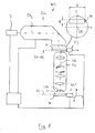
- Fig. 1 shows schematically a microlithographic projection exposure apparatus in the form of a wafer scanner WS, which is provided for fabricating large scale integrated semiconductor components in a step-and-scan mode.
- the projection exposure apparatus comprises as light source an KrF excimer laser S having an operating wavelength of about 248 nm. Other operating wavelengths, such as 193 nm or 157 nm, are also possible in other embodiments.
- An illumination system ILL generates, in its exit surface EX, a large, sharply delimited, homogeneously illuminated illumination field that is adapted to the telecentric requirements of the downstream catadioptric projection objective PO.
- the illumination system ILL has devices for selection of the illumination mode and, in the example, can be changed over between conventional on-axis illumination with a variable degree of coherence, and off-axis illumination, particularly annular illumination (having a ring shaped illuminated area in a pupil surface of the illumination system) and dipole or quadrupole illumination.
- a device RS reticle stage
- a device RS for holding and manipulating a mask M in such a way that a pattern formed on the mask lies in the exit surface EX of the illumination system coinciding with the object surface OS of the projection objective PO and can be moved in this plane for a scanning operation in a scanning direction (Y-direction) perpendicular to the optical axis OA l of the illumination system, which is parallel to, but laterally offset to the optical axis OA of the projection objective.
- the optical axes run parallel to the the Z-direction.
- the reduction projection objective PO is designed to image an image of a pattern provided by the mask with a reduced scale of 4:1 (magnification ratio
- 0.25) onto a wafer W coated with a photoresist layer.
- the wafer W serving as a light-sensitive substrate is arranged in such a way that the planar substrate surface SS with the photoresist layer essentially coincides with the planar image surface IS of the projection objective.
- the wafer is held by a device WST (wafer stage) comprising a scanner drive in order to move the wafer synchronously with the mask M in parallel with the latter.
- the device WS also comprises manipulators in order to move the wafer both in the Z direction parallel to the optical axis OA and in the X and Y directions perpendicular to said axis.
- a tilting device having at least one tilting axis running perpendicular to the optical axis is integrated.
- the projection objective PO has a flat, planoconvex lens as the last optical element LOE nearest to the image surface IS, the planar exit surface of that lens being the last optical surface (exit surface) of the projection objective PO.
- a gas filled gap is formed between the exit surface of the last optical element and the substrate surface SS.
- an immersion system where the working distance between the last optical element LOE and the wafer is filled with an immersion liquid (e.g. water).
- the last optical element LOE may be a plano-convex lens, providing a planar exit surface.
- the last optical element may be formed by a plane parallel plate, equally providing a planar exit surface of the projection objective.
- the exit surface of the projection objective may also be curved. Such curved exit surface may be provided by a last optical element formed like a biconvex lens, for example.
- the last optical surface (exit surface of the projection objective) may be concave.
- the illumination system ILL is capable of generating an illumination field having a rectangular shape.
- the position, size and shape of the illumination field determine the position, size and shape of the effective object field OF (and the effective image field IF) of the projection objective actually used in the projection process.
- the illumination system is designed to form an illumination field centered about the optical axis OA l of the illumination system.
- the optical axis of the illumination system is laterally offset relative to the optical axis OA of the projection objective to such an extent that the effective object field OF lies at the appropriate position entirely outside the optical axis of the projection objective required to obtain the imaging without vignetting (off-axis field).
- Fig. 2 shows a catadioptric projection objective 200 according to an embodiment of the invention designed for ca. 248 nm UV working wavelength. It is designed to project an image of a pattern on a reticle (mask) arranged in the planar object surface OS (object plane) into the planar image surface IS (image plane) on a reduced scale 4:1, while creating exactly two real intermediate images IMI1, IMI2.
- a first refractive objective part OP1 is designed for imaging the pattern in the object surface into the first intermediate image IMI1 at an enlarged scale with 1.5 ⁇
- a second, catoptric (purely reflective) objective part OP2 images the first intermediate image IMI1 into the second intermediate image IMI2 at a near unity magnification with 0.6 ⁇
- a third, refractive objective part OP3 images the second intermediate image IMI2 onto the image surface IS with a reduction ratio of about
- 0.2. The size of the second intermediate image is therefore significantly larger than the size of the effective image field.
- An aperture stop AS is placed in the third objective part in the region of the pupil surface PS3 thereof. In other embodiments, the aperture stop may be positioned in the first objective part at or near the pupil surface PS1 thereof.
- An off-axis effective object field OF positioned outside the optical axis OA is projected on an off-axis effective image field IF.
- the trajectory of a chief ray CR of an outer field point of the off-axis object field OF in the meridional plane (drawing plane) is drawn bold in order to facilitate following the beam path.
- the term "chief ray” (also known as principal ray) denotes a ray emanating from a field point away from the optical axis of the effectively used object field OF and intersecting the optical axis at at least one pupil surface position.
- three pupil surfaces PS1, PS2 and PS3 are formed, one pupil surface in each objective part.
- the chief ray emanates from the object surface parallel or at a very small angle with respect to the optical axis. As evident from the figure, the chief ray intersects both the object surface and the image surface essentially at right angles indicating both object-side and image-side telecentricity.
- the imaging process is further characterized by the trajectory of marginal rays.
- a "marginal ray” as used herein is a ray running from an axial object field point (on the optical axis) to the edge of an aperture stop AS. That marginal ray may not contribute to image formation because an off-axis effective object field is used to avoid vignetting.
- the chief ray and marginal ray are chosen to characterize optical properties of the projection objective.
- the first, refractive objective part OP1 includes, in this order between the object surface and the first intermediate image, a biconvex positive lens L1-1 with aspheric entry and spherical exit surface, a biconvex lens L1-2 with aspheric entry surface and spherical exit surface, a positive meniscus lens L1-3 having concave, aspheric entry surface and spherical exist surface, a biconvex positive lens L1-4 having aspheric entry surface and spherical exit surface, and a fifth lens formed by a second lens portion LP2-2 of a second catadioptric optical element COE2 discussed in detail below.
- the second purely reflective (catoptric) objective part OP2 comprises a first concave mirror CM1 having a concave mirror surface facing the object side, and a second concave mirror CM2 having the concave mirror surface facing the image side.
- the aspherically curved mirror surfaces are both continuous or unbroken, i.e. they do not have a hole or bore.
- the mirror surfaces facing each other define a catoptric cavity, which is also denoted intermirror space, enclosed by the curved surfaces defined by the concave mirrors.
- the intermediate images IMI1, IMI2 (at least the paraxial parts thereof) are both situated inside the cavity well apart from the mirror surfaces.
- Each mirror surface of a concave mirror defines a "curvature surface” or “surface of curvature” which is a mathematical surface extending beyond the edges of the physical mirror surface and containing the mirror surface.
- the first and second concave mirrors are parts of rotationally symmetric curvature surfaces having a common axis of rotational symmetry coinciding with the optical axis OA defined by the first and third objective parts (in-line system).
- the third, refractive objective part OP3 has, in this order between the second intermediate image IMI2 and the image surface IS, a first positive meniscus lens with concave, aspheric entry side and spherical exit side formed by a second lens portion LP2-1 of a first catadioptric optical element COE1, a thin positive lens L3-2 with aspheric exit surface, a group of two negative meniscus lenses L3-3, L3-4 concave on their exit sides, a group of two positive lenses, L3-5, L3-6 immediately upstream of the aperture stop AS, a group of four immediately consecutive positive lenses L3-7 to L3-10 converting the beam from the aperture stop towards the image surface, and a relatively flat plano-convex last optical element LOE having a planar exit surface arranged at a finite image side-working distance of about 6 mm from the image surface IS.
- the objective 200 is rotationally symmetric and has one straight optical axis OA common to all refractive and reflective optical components.
- the concave mirrors have small size and are arranged close together and rather close to the intermediate images lying in between.
- the concave mirrors are both off-axis sections of axial symmetric surfaces.
- the radiation beam passes by the edges of the concave mirrors facing the optical axis without vignetting.
- the exit pupil is circular without obscuration and is centered about the optical axis.
- the total number of lenses refracting the beam is 16, providing 32 refracting optical surfaces in total.
- the optical system includes two concave mirrors CM1, CM2, each providing positive optical power to converge incident radiation. Therefore, the total number of optical surfaces is 34 (32 refractive surfaces and 2 reflective surfaces).
- the 34 optical surfaces are provided by 16 optical components to be mounted successively in axial direction. Since both catadioptric optical elements COE1, COE2 each provide a concave mirror and a refracting lens portion, installation space can be used more effectively particularly in or close to the second objective part OP2 including the concave mirrors CM1, CM2.
- the body may also be made from an alkaline fluoride crystal material, such as calcium fluoride, extending the range of applicability to smaller wavelengths such as 157nm or below.
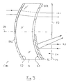
- the body has a concave first surface S1, which may be a spherical or an aspherical surface.
- a second surface S2 on the opposite side of body B may be convex, as in the embodiment.
- the second surface S2 may also be a planar surface or a concave surface, spherical or aspherical, as desired.
- the centers of curvatures of the first and second surface S1, S2 define the optical axis OA of the catadioptric optical element.
- the first surface S1 is coated with a dielectric anti-reflection coating AR1 across the entire area optically used in operation.
- second surface S2 is coated with a second anti-reflection coating AR2.
- a reflective coating RC is coated on the anti-reflection coating AR1 of a first surface S1 in a first portion P1 thereof.
- the reflective coating includes a metal layer made of aluminum deposited directly to the anti-reflection coating AR1, and a stack of alternating dielectric layers having different refractive index to protect the metal layer from corrosion and to enhance reflectivity of the reflective coating when compared to an uncoated metal layer.
- the first portion P1 covered with the reflective coating forms a concave mirror CM capable of reflecting radiation R1 incident from the concave side of the catadioptric optical element with positive optical power determined by the radius of curvature of the reflective coating.
- the reflective coating RC does not extend into the region of the optical axis OA or beyond.
- the reflective coating RC may cover more than 10% of the entire optically used area of the first surface S1, for example 20% or more, or 30% or more, or 40% or more.
- the first portion may be less than 50% or less than 60% or less than 70% of the entire optically used area of the first surface.
- the second portion P2 of the first surface only coated with the anti-reflection coating AR1 is transparent to the radiation and effective as a concave refractive optical surface.
- the second portion P2 forms a lens portion of the catadioptric optical element.
- the optical power of the lens portion is determined by the relative curvatures of the first and second surfaces and may have the action of a positive lens (as in the embodiment) or as a negative lens, where desired.
- the transparent portion P2 and the concave mirror CM are formed on the same optical surface (first surface S1) prepared with conventional optical preparation methods prior to coating with a reflective coating, the radius of curvature and, where applicable, the aspheric deformation, are the same for the concave, transparent lens portion P2 and the concave mirror CM.
- Both the concave refracting surface and the concave mirror will be positioned on the same axial position when the catadioptric optical element is mounted within an optical system.
- a single mounting structure is sufficient to mount both the lens portion P2 and the concave mirror CM formed by the reflective coating, whereby mounting is facilitated.
- two catadioptric optical elements are mounted at immediately consecutive position in the axial direction such that the concave sides are facing each other.
- the second catadioptric optical element COE2 is arranged such that the concave first surface is oriented towards the image surface.
- the first catadioptric optical element COE1 is arranged such that the concave first surface is oriented towards the object surface.
- Radiation coming from the object surface OS is first passed through the transparent lens portion LP2-2 of the second catadioptric optical element prior to forming the first intermediate image IMI1. Due to the relative surface curvatures of the first and second surface of the transparent body, this lens portion provides a small amount of positive refractive power.
- the aspheric shape of the concave first surface may contribute to defining the correction status of first intermediate image IMI1. Radiation is subsequently incident on the reflective coating of the first catadioptric optical element COE1 forming the first concave mirror CM1.
- First concave mirror CM1 reflects radiation backwards and inwardly to cross the optical axis OA prior to incidence on second concave mirror CM2 formed by the reflective coating of the second catadioptric optical element COE2.
- the positive optical power of second concave mirror CM2 converges the beam towards the second intermediate image IMI2 formed immediately downstream of the second concave mirror CM2 and upstream of the transparent second portion LP2-1 of first catadioptric optical element COE1.
- the transparent second portion of first catadioptric optical element COE1 acts in a manner of the field lens on the radiation and may contribute to optical correction.
- One or more baffles or blinds may be provided, for example between the reflective portion and the transmissive portion of a surface area of one or both catadioptric optical elements, to prevent stray light from interfering with the image formation in the image surface IS of the projection objective.
- the total track length (axial distance between object surface and image surface) is 1250 mm.
- the optical correction for aberrations is characterized by a root-mean-square (RMS) of the wavefront error equal to or smaller than 4 m ⁇ for all image heights.
- RMS root-mean-square
- the overall number of lenses is equal to the overall number of optical elements. All lenses are made of fused silica. Typical resolutions of R ⁇ 80 nm can be obtained.
- Column 1 specifies the number of a refractive surface or a reflective surface or a surface distinguished in some other way
- column 2 specifies the radius r (radius of curvature) of the surface (in mm)
- column 3 specifies the distance d - also denoted as thickness - between the surface and the subsequent surface (in mm)
- column 4 specifies the material of the optical components.
- Column 5 indicates the refractive index of the material
- column 6 specifies the optically free radius or the optically free semidiameter (or the lens height) of a lens surface or other surfaces (in mm).
- Table 2A specifies the corresponding aspheric data.
- the reciprocal (1/r) of the radius specifies the surface curvature and h specifies the distance between a surface point and the optical axis (i.e. the ray height). Consequently, p(h) specifies the so-called sagitta, that is to say the distance between the surface point and the surface vertex in the z direction (direction of the optical axis).
- Constant K is the conic constant, and parameters, C1, C2 are aspheric constants.
Priority Applications (1)
| Application Number | Priority Date | Filing Date | Title |
|---|---|---|---|
| EP07018247A EP1936421A1 (fr) | 2007-09-18 | 2007-09-18 | Système optique catadioptrique et élément optique catadioptrique |
Applications Claiming Priority (1)
| Application Number | Priority Date | Filing Date | Title |
|---|---|---|---|
| EP07018247A EP1936421A1 (fr) | 2007-09-18 | 2007-09-18 | Système optique catadioptrique et élément optique catadioptrique |
Publications (1)
| Publication Number | Publication Date |
|---|---|
| EP1936421A1 true EP1936421A1 (fr) | 2008-06-25 |
Family
ID=38984159
Family Applications (1)
| Application Number | Title | Priority Date | Filing Date |
|---|---|---|---|
| EP07018247A Withdrawn EP1936421A1 (fr) | 2007-09-18 | 2007-09-18 | Système optique catadioptrique et élément optique catadioptrique |
Country Status (1)
| Country | Link |
|---|---|
| EP (1) | EP1936421A1 (fr) |
Cited By (3)
| Publication number | Priority date | Publication date | Assignee | Title |
|---|---|---|---|---|
| US7869122B2 (en) | 2004-01-14 | 2011-01-11 | Carl Zeiss Smt Ag | Catadioptric projection objective |
| US8199400B2 (en) | 2004-01-14 | 2012-06-12 | Carl Zeiss Smt Gmbh | Catadioptric projection objective |
| US8913316B2 (en) | 2004-05-17 | 2014-12-16 | Carl Zeiss Smt Gmbh | Catadioptric projection objective with intermediate images |
Citations (4)
| Publication number | Priority date | Publication date | Assignee | Title |
|---|---|---|---|---|
| EP0266005A2 (fr) * | 1986-10-28 | 1988-05-04 | Philips Norden AB | Objectif à miroirs et arrangement optique contenant deux objectifs à miroirs |
| EP0433613A1 (fr) * | 1989-11-03 | 1991-06-26 | Horiba, Ltd. | Spectromètre microscopique avec objectif du type Cassegrain |
| WO1999047949A1 (fr) * | 1998-03-16 | 1999-09-23 | Questar Corporation | Microscope stereoscopique longue distance |
| WO2005069055A2 (fr) * | 2004-01-14 | 2005-07-28 | Carl Zeiss Smt Ag | Objectif de projection catadioptrique |
-
2007
- 2007-09-18 EP EP07018247A patent/EP1936421A1/fr not_active Withdrawn
Patent Citations (4)
| Publication number | Priority date | Publication date | Assignee | Title |
|---|---|---|---|---|
| EP0266005A2 (fr) * | 1986-10-28 | 1988-05-04 | Philips Norden AB | Objectif à miroirs et arrangement optique contenant deux objectifs à miroirs |
| EP0433613A1 (fr) * | 1989-11-03 | 1991-06-26 | Horiba, Ltd. | Spectromètre microscopique avec objectif du type Cassegrain |
| WO1999047949A1 (fr) * | 1998-03-16 | 1999-09-23 | Questar Corporation | Microscope stereoscopique longue distance |
| WO2005069055A2 (fr) * | 2004-01-14 | 2005-07-28 | Carl Zeiss Smt Ag | Objectif de projection catadioptrique |
Non-Patent Citations (1)
| Title |
|---|
| MAKSUTOV D D: "NEW CATADIOPTRIC MENISCUS SYSTEMS", JOURNAL OF THE OPTICAL SOCIETY OF AMERICA, AMERICAN INSTITUTE OF PHYSICS. NEW YORK, US, vol. 34, no. 5, May 1944 (1944-05-01), pages 270 - 284, XP001014193 * |
Cited By (16)
| Publication number | Priority date | Publication date | Assignee | Title |
|---|---|---|---|---|
| US8730572B2 (en) | 2004-01-14 | 2014-05-20 | Carl Zeiss Smt Gmbh | Catadioptric projection objective |
| US8355201B2 (en) | 2004-01-14 | 2013-01-15 | Carl Zeiss Smt Gmbh | Catadioptric projection objective |
| US8208198B2 (en) | 2004-01-14 | 2012-06-26 | Carl Zeiss Smt Gmbh | Catadioptric projection objective |
| US8208199B2 (en) | 2004-01-14 | 2012-06-26 | Carl Zeiss Smt Gmbh | Catadioptric projection objective |
| US7869122B2 (en) | 2004-01-14 | 2011-01-11 | Carl Zeiss Smt Ag | Catadioptric projection objective |
| US8339701B2 (en) | 2004-01-14 | 2012-12-25 | Carl Zeiss Smt Gmbh | Catadioptric projection objective |
| US8199400B2 (en) | 2004-01-14 | 2012-06-12 | Carl Zeiss Smt Gmbh | Catadioptric projection objective |
| US8416490B2 (en) | 2004-01-14 | 2013-04-09 | Carl Zeiss Smt Gmbh | Catadioptric projection objective |
| US8289619B2 (en) | 2004-01-14 | 2012-10-16 | Carl Zeiss Smt Gmbh | Catadioptric projection objective |
| US8804234B2 (en) | 2004-01-14 | 2014-08-12 | Carl Zeiss Smt Gmbh | Catadioptric projection objective including an aspherized plate |
| US8908269B2 (en) | 2004-01-14 | 2014-12-09 | Carl Zeiss Smt Gmbh | Immersion catadioptric projection objective having two intermediate images |
| US9772478B2 (en) | 2004-01-14 | 2017-09-26 | Carl Zeiss Smt Gmbh | Catadioptric projection objective with parallel, offset optical axes |
| US9019596B2 (en) | 2004-05-17 | 2015-04-28 | Carl Zeiss Smt Gmbh | Catadioptric projection objective with intermediate images |
| US9134618B2 (en) | 2004-05-17 | 2015-09-15 | Carl Zeiss Smt Gmbh | Catadioptric projection objective with intermediate images |
| US9726979B2 (en) | 2004-05-17 | 2017-08-08 | Carl Zeiss Smt Gmbh | Catadioptric projection objective with intermediate images |
| US8913316B2 (en) | 2004-05-17 | 2014-12-16 | Carl Zeiss Smt Gmbh | Catadioptric projection objective with intermediate images |
Similar Documents
| Publication | Publication Date | Title |
|---|---|---|
| US7712905B2 (en) | Imaging system with mirror group | |
| EP1709472B1 (fr) | Objectif de projection catadioptrique | |
| US7301707B2 (en) | Projection optical system and method | |
| JP5883778B2 (ja) | 入射瞳のバック・フォーカスが負である投影対物系および投影露光装置 | |
| US7006304B2 (en) | Catadioptric reduction lens | |
| EP1318425B1 (fr) | Système optique catadioptrique et dispositif d'exposition muni d'un tel système | |
| EP2372404B1 (fr) | Appareil d'exposition de projection et objectif de projection à grande ouverture, à transmission élevée | |
| US7403262B2 (en) | Projection optical system and exposure apparatus having the same | |
| KR20100052515A (ko) | 색 보정된 반사굴절 대물부 및 이를 포함하는 투영 노광 장치 | |
| US9146475B2 (en) | Projection exposure system and projection exposure method | |
| US7848016B2 (en) | High-NA projection objective | |
| US8441613B2 (en) | Projection objective and projection exposure apparatus for microlithography | |
| US20100172019A1 (en) | Projection objective and projection exposure apparatus including the same | |
| US7957069B2 (en) | Projection optical system | |
| EP1936421A1 (fr) | Système optique catadioptrique et élément optique catadioptrique | |
| US8780441B2 (en) | Catadioptric projection objective with pupil correction | |
| EP1927891A1 (fr) | Objectif de projection avec pupilles conjuguées | |
| US20090086338A1 (en) | High Aperture Folded Catadioptric Projection Objective | |
| WO2008101676A2 (fr) | Objectif de projection catadioptrique avec ouverture numérique ultra-élevée | |
| US20090091728A1 (en) | Compact High Aperture Folded Catadioptric Projection Objective | |
| JP5567098B2 (ja) | 瞳補正を有する反射屈折投影対物系 | |
| EP2196838A1 (fr) | Élément électroluminescent, dispositif électroluminescent et dispositif électronique |
Legal Events
| Date | Code | Title | Description |
|---|---|---|---|
| PUAI | Public reference made under article 153(3) epc to a published international application that has entered the european phase |
Free format text: ORIGINAL CODE: 0009012 |
|
| AK | Designated contracting states |
Kind code of ref document: A1 Designated state(s): AT BE BG CH CY CZ DE DK EE ES FI FR GB GR HU IE IS IT LI LT LU LV MC MT NL PL PT RO SE SI SK TR |
|
| AX | Request for extension of the european patent |
Extension state: AL BA HR MK RS |
|
| AKX | Designation fees paid | ||
| STAA | Information on the status of an ep patent application or granted ep patent |
Free format text: STATUS: THE APPLICATION IS DEEMED TO BE WITHDRAWN |
|
| 18D | Application deemed to be withdrawn |
Effective date: 20081230 |
|
| REG | Reference to a national code |
Ref country code: DE Ref legal event code: 8566 |