EP1936210A1 - Locking Expanding Diameter Fasteners - Google Patents
Locking Expanding Diameter Fasteners Download PDFInfo
- Publication number
- EP1936210A1 EP1936210A1 EP06270105A EP06270105A EP1936210A1 EP 1936210 A1 EP1936210 A1 EP 1936210A1 EP 06270105 A EP06270105 A EP 06270105A EP 06270105 A EP06270105 A EP 06270105A EP 1936210 A1 EP1936210 A1 EP 1936210A1
- Authority
- EP
- European Patent Office
- Prior art keywords
- bolts
- fastener
- mounting plate
- collet
- shank
- Prior art date
- Legal status (The legal status is an assumption and is not a legal conclusion. Google has not performed a legal analysis and makes no representation as to the accuracy of the status listed.)
- Withdrawn
Links
- 230000015572 biosynthetic process Effects 0.000 claims abstract description 10
- 230000007246 mechanism Effects 0.000 claims description 15
- 230000000452 restraining effect Effects 0.000 claims description 2
- 230000003019 stabilising effect Effects 0.000 claims description 2
- 239000002184 metal Substances 0.000 claims 1
- 238000005755 formation reaction Methods 0.000 abstract 2
- 238000009434 installation Methods 0.000 description 3
- 238000000034 method Methods 0.000 description 2
- RZVHIXYEVGDQDX-UHFFFAOYSA-N 9,10-anthraquinone Chemical compound C1=CC=C2C(=O)C3=CC=CC=C3C(=O)C2=C1 RZVHIXYEVGDQDX-UHFFFAOYSA-N 0.000 description 1
- 229910000639 Spring steel Inorganic materials 0.000 description 1
- 230000008901 benefit Effects 0.000 description 1
- 210000000988 bone and bone Anatomy 0.000 description 1
- 238000010276 construction Methods 0.000 description 1
- 230000008878 coupling Effects 0.000 description 1
- 238000010168 coupling process Methods 0.000 description 1
- 238000005859 coupling reaction Methods 0.000 description 1
- 230000000694 effects Effects 0.000 description 1
- 230000014759 maintenance of location Effects 0.000 description 1
- 239000000463 material Substances 0.000 description 1
- 230000004048 modification Effects 0.000 description 1
- 238000012986 modification Methods 0.000 description 1
- 230000008569 process Effects 0.000 description 1
- 238000012797 qualification Methods 0.000 description 1
Images





Classifications
-
- F—MECHANICAL ENGINEERING; LIGHTING; HEATING; WEAPONS; BLASTING
- F16—ENGINEERING ELEMENTS AND UNITS; GENERAL MEASURES FOR PRODUCING AND MAINTAINING EFFECTIVE FUNCTIONING OF MACHINES OR INSTALLATIONS; THERMAL INSULATION IN GENERAL
- F16B—DEVICES FOR FASTENING OR SECURING CONSTRUCTIONAL ELEMENTS OR MACHINE PARTS TOGETHER, e.g. NAILS, BOLTS, CIRCLIPS, CLAMPS, CLIPS OR WEDGES; JOINTS OR JOINTING
- F16B39/00—Locking of screws, bolts or nuts
- F16B39/02—Locking of screws, bolts or nuts in which the locking takes place after screwing down
- F16B39/10—Locking of screws, bolts or nuts in which the locking takes place after screwing down by a plate, spring, wire or ring immovable with regard to the bolt or object and mainly perpendicular to the axis of the bolt
- F16B39/101—Locking of screws, bolts or nuts in which the locking takes place after screwing down by a plate, spring, wire or ring immovable with regard to the bolt or object and mainly perpendicular to the axis of the bolt with a plate, spring, wire or ring holding two or more nuts or bolt heads which are mainly in the same plane
-
- F—MECHANICAL ENGINEERING; LIGHTING; HEATING; WEAPONS; BLASTING
- F16—ENGINEERING ELEMENTS AND UNITS; GENERAL MEASURES FOR PRODUCING AND MAINTAINING EFFECTIVE FUNCTIONING OF MACHINES OR INSTALLATIONS; THERMAL INSULATION IN GENERAL
- F16B—DEVICES FOR FASTENING OR SECURING CONSTRUCTIONAL ELEMENTS OR MACHINE PARTS TOGETHER, e.g. NAILS, BOLTS, CIRCLIPS, CLAMPS, CLIPS OR WEDGES; JOINTS OR JOINTING
- F16B3/00—Key-type connections; Keys
- F16B3/06—Key-type connections; Keys using taper sleeves
Definitions
- This invention relates the locking of expanding diameter fastener for aerospace applications.
- EDF Expanding Diameter Fasteners
- aerospace applications where very large loads may be exerted on the fastener, e.g. for suspending an aircraft in a hangar.
- the diameter of the fastener may be several inches.
- a known type of EDF comprises a collet, formed as a split ring, located around the shank of a threaded bolt. The collet and shank have cooperating surfaces such that, when the bolt is tightened within a borehole, the collet expands radially outwardly to lock the bolt within the borehole.
- the invention provides an expanding diameter fastener, comprising a shank member for location within an aperture, a collet means surrounding the shank member, the collet means and the shank member having cooperating surfaces such that relative axial movement causes outward radial expansion of the collet means to lock the fastener within the aperture, an array, comprising a plurality of bolts, disposed around said shank, a pressure member disposed between said array and said collet means, such that tightening of said bolts creates an axial movement which is transmitted via said pressure member to said collet means, and a means for locking each of said bolts in a tightened condition.
- a locking means may be provided for locking each bolt in a tightened condition, so as to maintain the torque setting over the course of time.
- each bolt may comprise a quick-release mechanism which is preset to a specific torque setting when locked.
- threaded bolts since the primary application of the invention is for high value loads on the fastener, it is preferred to use threaded bolts. A separate mechanism is then required to lock each bolt in its initial torque setting.
- each bolt is desirably set to a specific torque value, this implies that the head of the bolt is spaced from its mounting. This therefore precludes the use of known tab locking devices.
- Such locking means may comprise a cable or wire wound around the shank of each bolt between the bolt head and a mounting plate for the bolt array.
- the locking means may comprise a distorted threaded bone in the bolt mounting plate.
- a tab washer device is applied to the bolt mounting plate subsequent to bolt tightening. A respective tab on the washer abuts a facet of each bolt head to prevent the bolt head from rotating. All of the above possibilities for locking suffer from disadvantages which will be explained in detail below.
- each bolt head of the array is formed to cooperate with a device so as to create a ratchet mechanism. This ensures that each bolt head is held in its desired torque setting by means of the ratchet mechanism. Further the ratchet mechanism permits a precise torque setting.
- each bolt head of the array is formed with a ratchet wheel formation, in addition to facets for receiving a tightening mechanism such as a spanner or hex hey.
- a pawl mechanism is provided on the bolt mounting plate for cooperating with each bolt head.
- a preferred mechanism is a single lock member which is releasably fixed to the mounting plate, and which includes a plurality of spring fingers, each of which is arranged for engaging the respective ratchet formation of a bolt head.
- the lock member includes a band portion which may be clipped onto the periphery of the mounting plate. The band portion is integral with the spring fingers. Additionally locating and stabilising fingers may be provided engaging with the surface of the mounting plate.
- the invention provides an expanding diameter fastener, comprising a shank member for location with an aperture, a collet means surrounding the shank member, the collet means and the shank member having cooperating surfaces such that relative axial movement causes outward radial expansion of the collet means to lock the fastener within the aperture, an array, comprising a plurality of bolts, disposed around said shank member, a pressure member disposed between said array and said collet means, such that tightening of said bolts creates an axial movement which is transmitted via said pressure member to said collet means, and a locking means for locking each of said bolts in a tightened condition, said locking means comprising a ratchet mechanism, for restraining each bolt from loosening rotation.
- the present invention proposes a revised method of expanding tapered collets, utilising a circular array of smaller threaded bolts. Once the Fastener is correctly located, each bolt is torque to the correct value. Since the shoulders of these bolts do not seat on the threaded plate, as a gap must always be present for a correct torque setting, this precludes the use of conventional tab locking devices.
- the EDF comprises a cylindrical shank member 2 having a reduced diameter upper section 4, which tapers from the main part of member 2 in a tapering wall surface 6.
- a collet 8 formed as a split ring, disposed around upper section 4 in the region of surface 6, is formed with a tapering inner surface 10 which engages surface 6 to permit relative sliding movement.
- a disc shaped pressure plate 12 is slidably located on section 4 above collet 8 and has a lower edge surface 14 for engaging collet 8.
- the upper surface 16 of the pressure plate has recesses 18 for receiving the free ends of bolts 20.
- the top of the fastener has a disc-shaped mounting plate 22 secured around section 4.
- Plate 22 has four threaded bores 24 for receiving four threaded bolts 20 arranged in a regular array.
- Bolts 24 have hexagonal shaped heads 26.
- the top of section 4 has a hexagonal recess 28 for receiving a hex key.
- shank 2 is inserted into a bore or other locating aperture or recess (not shown).
- Bolts 20 are tightened, according to a predetermined sequence and until desired torques are reached, so that their free ends engage in recesses 18, to push pressure plate 12 downward by into abutment with the top edge of collet 8.
- This causes collet 8 to move downwardly, and relative movement between tapered surfaces 6, 10 causes the collet to expand radially outwardly to engage the inner wall of the locating recess, to fix the EDF in position.
- the heads 26 of bolts 20 are spaced from the upper surface of plate 22. In order to fix the bolts 20 in position, and to maintain the torque setting, the following measures may be undertaken.
- a wire 30, known by the trade mark Safe-T-Cable is wound around the shanks of bolts 20 beneath the heads in order to jam the bolts in position.
- Safe-T-Cable is wound around the shanks of bolts 20 beneath the heads in order to jam the bolts in position.
- this embodiment may be difficult for an operator to operate where the fastener is located in an inaccessible position, and gives rise to an unacceptable FOD hazard.
- the heads 40 of bolts 20 are formed with recesses 42 to receive a hex key.
- the threaded bores 24 of plate 22 have distorted threaded holes in order to provide a locking effect.
- additional torque may be required to overcome the resistance of the distorted thread, and this is not constant or repeatable.
- the resistance of the distorted thread may diminish with wear and number of repeat operations. This may make this embodiment unsuitable for certain applications.
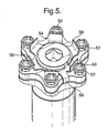
- the heads of bolts 20 are formed with hex key recesses 50, and hexagonal facets 52.
- a tab washer 54 is provided, having a series of tabs 56 which are arranged to engage hexagonal facets 52 for locking of the bolts.
- a locating tab 58 is provided engaging the edge of maintaining plate 22. This embodiment requires that each bolt 20 is oriented to align a hex face 52 normal to the pin axis before the washer 54 can be introduced.
- the retention of tab washer 54 by means of tab 58 requires additional part or process. Permanent deformation of the washer requires discarding and replacement of tab washer for each disassembly/assembly operation.
- each bolt 20 has a head formed with a six part ratchet cam formation 60 around its periphery.
- each bolt has a recess 62 for receiving a hex key.
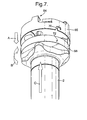
- a pawl mechanism is provided comprising a lock member 64 having an annular band 65 for clipping onto the circular edge 68 of the mounting plate (see Figure 7 ).
- a bayonet recess 70 in band 65 engages a pin 72 located on edge 68.
- Clip member 64 is formed of spring steel, and includes a series of four inwardly directed fingers 66, each of which is arranged to engage a respective ratchet formation 60 of a bolt 20, and to act as a spring pawl element.
- locating fingers 74 are provided engaging the upper surface of plate 22, for providing stability and rigidity. As can be seen from Figure 8 , finger 74 is closely adjacent ratchet formation 60, allowing each bolt to be torqued to a precise required value without significant additional resistance. Rotation of the bolt in a loosening direction is prevented by finger 74 engaging the ratchet cams. There is an additional benefit of an audible indication of incremental tightening during sequential tightening of the bolts, allowing precise tightening steps.
- the lock member or clip 64 In order to loosen the Fastener, the lock member or clip 64 must first be removed. This is achieved as shown in Figure 7 , by (1) pushing the clip downwardly in the direction of arrow A, (2) rotating the clip in the direction of arrow B, and (3) lifting the clip in the direction of arrow C, in order to release the bayonet coupling 70, 72.
- a six bolt array instead of the four shown, may allow smaller sized components, offering weight saving and/or better space constraint, but at the cost of additional installation time.
- the collet means may be combined with the pressure member on which the bolt pressed has a simplification in construction.
Landscapes
- Engineering & Computer Science (AREA)
- General Engineering & Computer Science (AREA)
- Mechanical Engineering (AREA)
- Bolts, Nuts, And Washers (AREA)
Abstract
An expanding diameter fastener for aerospace applications where a precise locking torque setting is required comprises an array of bolts (20) disposed around the shank (2) of the fastener, arranged to act on an expandable collet (8) to lock the fastener, where each bolt has a ratchet formation (60) on its head, and a releasable lock member (64) is clipped to the fastener having finger portions (66) for engaging respective ratchet formations to lock the bolts against loosening rotation.
Description
- This invention relates the locking of expanding diameter fastener for aerospace applications.
- It is known to provide Expanding Diameter Fasteners (EDF) for aerospace applications, where very large loads may be exerted on the fastener, e.g. for suspending an aircraft in a hangar. In such cases the diameter of the fastener may be several inches. A known type of EDF comprises a collet, formed as a split ring, located around the shank of a threaded bolt. The collet and shank have cooperating surfaces such that, when the bolt is tightened within a borehole, the collet expands radially outwardly to lock the bolt within the borehole.
- Problems with such EDF are that, partly on account of its large size, high installation torques is required to overcome frictional forces arising during tightening, and it becomes very difficult to tighten the fastener to a specific torque value (which specific accuracy may be required in an aerospace application). Further over the course of time, the fastener may loosen from its initial torque setting.
- It is an object of the invention to provide an expanding diameter fastener for aerospace applications, where the problems referred to above are largely overcome, or at least reduced.
- The invention provides an expanding diameter fastener, comprising a shank member for location within an aperture, a collet means surrounding the shank member, the collet means and the shank member having cooperating surfaces such that relative axial movement causes outward radial expansion of the collet means to lock the fastener within the aperture,
an array, comprising a plurality of bolts, disposed around said shank, a pressure member disposed between said array and said collet means, such that tightening of said bolts creates an axial movement which is transmitted via said pressure member to said collet means, and a means for locking each of said bolts in a tightened condition. - The provision of an array of bolts for tightening the fastener implies that the load on each bolt is correspondingly reduced for a required overall load. Hence frictional forces on each bolt arising during tightening are reduced, and the attainment of a specific torque value setting for the bolt is simplified. In particular, such an arrangement does not affect the fastener loading torque, it does not generate discard materials or parts (which could pose a "Foreign Object Damage" (FOD) risk in an aerospace application), and it is easily achievable to a standard suitable for qualification for use in primary flight control systems.
- A locking means may be provided for locking each bolt in a tightened condition, so as to maintain the torque setting over the course of time. In some circumstances, each bolt may comprise a quick-release mechanism which is preset to a specific torque setting when locked. However, since the primary application of the invention is for high value loads on the fastener, it is preferred to use threaded bolts. A separate mechanism is then required to lock each bolt in its initial torque setting.
- Since each bolt is desirably set to a specific torque value, this implies that the head of the bolt is spaced from its mounting. This therefore precludes the use of known tab locking devices. Such locking means may comprise a cable or wire wound around the shank of each bolt between the bolt head and a mounting plate for the bolt array. Alternatively the locking means may comprise a distorted threaded bone in the bolt mounting plate. Another possibility is that a tab washer device is applied to the bolt mounting plate subsequent to bolt tightening. A respective tab on the washer abuts a facet of each bolt head to prevent the bolt head from rotating. All of the above possibilities for locking suffer from disadvantages which will be explained in detail below.
- In a specific and preferred form of the invention, each bolt head of the array is formed to cooperate with a device so as to create a ratchet mechanism. This ensures that each bolt head is held in its desired torque setting by means of the ratchet mechanism. Further the ratchet mechanism permits a precise torque setting. In a preferred form, each bolt head of the array is formed with a ratchet wheel formation, in addition to facets for receiving a tightening mechanism such as a spanner or hex hey. A pawl mechanism is provided on the bolt mounting plate for cooperating with each bolt head. Whilst such pawl mechanism may take a variety of forms, for example a separate sprung pawl element mounted adjacent each bolt head, a preferred mechanism is a single lock member which is releasably fixed to the mounting plate, and which includes a plurality of spring fingers, each of which is arranged for engaging the respective ratchet formation of a bolt head. The lock member includes a band portion which may be clipped onto the periphery of the mounting plate. The band portion is integral with the spring fingers. Additionally locating and stabilising fingers may be provided engaging with the surface of the mounting plate.
- Thus, in a second specific aspect, the invention provides an expanding diameter fastener, comprising a shank member for location with an aperture, a collet means surrounding the shank member, the collet means and the shank member having cooperating surfaces such that relative axial movement causes outward radial expansion of the collet means to lock the fastener within the aperture,
an array, comprising a plurality of bolts, disposed around said shank member, a pressure member disposed between said array and said collet means, such that tightening of said bolts creates an axial movement which is transmitted via said pressure member to said collet means, and a locking means for locking each of said bolts in a tightened condition, said locking means comprising a ratchet mechanism, for restraining each bolt from loosening rotation. - Preferred embodiments of the invention will now be described with reference to the accompanying drawings wherein:-
-
Figure 1 is a top plan view of an expanding diameter fastener according to the invention, but excluding a bolt locking mechanism; -
Figure 2 is a side view of the fastener ofFigure 1 ; -
Figure 3 is a is a perspective view of a first embodiment of the invention, incorporating the fastener ofFigure 1 and a locking cable; -
Figure 4 is a perspective view of a second embodiment of the invention, incorporating the fastener ofFigure 1 and locking threads; -
Figure 5 is a perspective view of a second embodiment of the invention, incorporating the fastener ofFigure 1 and a locking tab washer; -
Figure 6a is a perspective view of a fourth and preferred embodiment of the invention, incorporating the fastener ofFigure 1 , and a ratchet locking mechanism; -
Figure 6b is a view of the embodiment ofFigure 6a from a different perspective; -
Figure 6c is an exploded view of the embodiment ofFigures 6a and6b . -
Figure 7 is a rear perspective and exploded view of the preferred embodiment of the invention; and -
Figure 8 is a detail perspective view of a single bolt of the preferred embodiment, showing a ratchet formation on the bolt head. - In development of Expanding Diameter Fasteners for aerospace applications, e.g. for a Horizontal Tail hinge, high installation loads have been experienced, which means compromise the intended application. The present invention proposes a revised method of expanding tapered collets, utilising a circular array of smaller threaded bolts. Once the Fastener is correctly located, each bolt is torque to the correct value. Since the shoulders of these bolts do not seat on the threaded plate, as a gap must always be present for a correct torque setting, this precludes the use of conventional tab locking devices.
- Referring to
Figures 1 and 2 , there is shown an Expanding Diameter Fastener (EDF) which is incorporated in the embodiments of the invention described below. The EDF comprises acylindrical shank member 2 having a reduced diameterupper section 4, which tapers from the main part ofmember 2 in a taperingwall surface 6. Acollet 8, formed as a split ring, disposed aroundupper section 4 in the region ofsurface 6, is formed with a taperinginner surface 10 which engagessurface 6 to permit relative sliding movement. A disc shapedpressure plate 12 is slidably located onsection 4 abovecollet 8 and has alower edge surface 14 forengaging collet 8. The upper surface 16 of the pressure plate has recesses 18 for receiving the free ends ofbolts 20. - The top of the fastener has a disc-
shaped mounting plate 22 secured aroundsection 4.Plate 22 has four threadedbores 24 for receiving four threadedbolts 20 arranged in a regular array.Bolts 24 have hexagonalshaped heads 26. In addition the top ofsection 4 has ahexagonal recess 28 for receiving a hex key. - In use,
shank 2 is inserted into a bore or other locating aperture or recess (not shown).Bolts 20 are tightened, according to a predetermined sequence and until desired torques are reached, so that their free ends engage inrecesses 18, to pushpressure plate 12 downward by into abutment with the top edge ofcollet 8. This causescollet 8 to move downwardly, and relative movement betweentapered surfaces - In the secured position, the
heads 26 ofbolts 20 are spaced from the upper surface ofplate 22. In order to fix thebolts 20 in position, and to maintain the torque setting, the following measures may be undertaken. - In the first embodiment shown in
Figure 3 , awire 30, known by the trade mark Safe-T-Cable, is wound around the shanks ofbolts 20 beneath the heads in order to jam the bolts in position. However this embodiment may be difficult for an operator to operate where the fastener is located in an inaccessible position, and gives rise to an unacceptable FOD hazard. - In a second embodiment shown in
Figure 4 theheads 40 ofbolts 20 are formed withrecesses 42 to receive a hex key. The threaded bores 24 ofplate 22 have distorted threaded holes in order to provide a locking effect. However additional torque may be required to overcome the resistance of the distorted thread, and this is not constant or repeatable. The resistance of the distorted thread may diminish with wear and number of repeat operations. This may make this embodiment unsuitable for certain applications. - In a third embodiment shown in
Figure 5 , the heads ofbolts 20 are formed with hex key recesses 50, andhexagonal facets 52. Atab washer 54 is provided, having a series oftabs 56 which are arranged to engagehexagonal facets 52 for locking of the bolts. In addition a locatingtab 58 is provided engaging the edge of maintainingplate 22. This embodiment requires that eachbolt 20 is oriented to align ahex face 52 normal to the pin axis before thewasher 54 can be introduced. The retention oftab washer 54 by means oftab 58 requires additional part or process. Permanent deformation of the washer requires discarding and replacement of tab washer for each disassembly/assembly operation. - Referring now to the fourth and preferred embodiment shown in
Figures 6 to 8 , eachbolt 20 has a head formed with a six partratchet cam formation 60 around its periphery. In addition each bolt has arecess 62 for receiving a hex key. A pawl mechanism is provided comprising alock member 64 having anannular band 65 for clipping onto thecircular edge 68 of the mounting plate (seeFigure 7 ). In addition abayonet recess 70 inband 65 engages apin 72 located onedge 68.Clip member 64 is formed of spring steel, and includes a series of four inwardly directedfingers 66, each of which is arranged to engage arespective ratchet formation 60 of abolt 20, and to act as a spring pawl element. In addition four locatingfingers 74 are provided engaging the upper surface ofplate 22, for providing stability and rigidity. As can be seen fromFigure 8 ,finger 74 is closelyadjacent ratchet formation 60, allowing each bolt to be torqued to a precise required value without significant additional resistance. Rotation of the bolt in a loosening direction is prevented byfinger 74 engaging the ratchet cams. There is an additional benefit of an audible indication of incremental tightening during sequential tightening of the bolts, allowing precise tightening steps. - In order to loosen the Fastener, the lock member or
clip 64 must first be removed. This is achieved as shown inFigure 7 , by (1) pushing the clip downwardly in the direction of arrow A, (2) rotating the clip in the direction of arrow B, and (3) lifting the clip in the direction of arrow C, in order to release thebayonet coupling - In a modification, a six bolt array, instead of the four shown, may allow smaller sized components, offering weight saving and/or better space constraint, but at the cost of additional installation time.
- In some situations, the collet means may be combined with the pressure member on which the bolt pressed has a simplification in construction.
Claims (10)
- An expanding diameter fastener, comprising a shank member for location within a locating recess, a collet means surrounding the shank member, the collet means and the shank member having cooperating surfaces such that relative axial movement causes outward radial expansion of the collet means to lock the fastener within the recess, an array comprising a plurality of bolts, disposed around said shank member, a pressure member disposed between said array and said collet means, such that tightening of said bolts creates an axial movement which is transmitted via said pressure member to said collet means, and a locking means for locking each of said bolts in a tightened condition.
- A fastener as claimed in claim 1, wherein said bolts are located in threaded apertures in a mounting plate secured to said shank member.
- A fastener as claimed in claim 2 wherein said locking means comprises one of : a wire wound around the shanks of the bolts between their heads and the mounting plate, distorted threads in said threaded apertures; and a tab washer located on said mounting plate and having a respective upstanding tab for abutting against a facet of each bolt head.
- An expanding diameter fastener, comprising a shank member for location within a locating recess, a collet means surrounding the shank member, the collet means and the shank member having cooperating surfaces such that relative axial movement causes outward radial expansion of the collet means to lock the fastener within the recess, an array comprising a plurality of bolts, disposed around said shank, a pressure member disposed between said array and said collet means, such that tightening of said bolts creates an axial movement which is transmitted via said pressure member to said collet means, and a locking means for locking each of said bolts in a tightened condition, said locking means comprising a ratchet mechanism for restraining each bolt from loosening rotation.
- A fastener according to claim 4, wherein each of said bolts includes a ratchet wheel formation and including a pawl means for engaging with each ratchet wheel formation.
- A fastener according to claim 5, wherein said bolts are located in a mounting plate secured to said shank member, and including a lock member located on said mounting plate, said lock member including finger portions comprising said pawl means.
- A fastener according to claim 6, wherein said lock member includes a band portion for releasably clipping around the periphery of the mounting plate.
- A fastener according to claim 7, including a bayonet mechanism for securing said band portion to said mounting plate.
- A fastener according to claim 6 or 7, wherein said lock member includes stabilising finger portions for engaging the upper surface of said mounting plate.
- A fastener according to any of claims 6 to 9, wherein said lock member is formed of spring metal strip.
Priority Applications (1)
| Application Number | Priority Date | Filing Date | Title |
|---|---|---|---|
| EP06270105A EP1936210A1 (en) | 2006-12-19 | 2006-12-19 | Locking Expanding Diameter Fasteners |
Applications Claiming Priority (1)
| Application Number | Priority Date | Filing Date | Title |
|---|---|---|---|
| EP06270105A EP1936210A1 (en) | 2006-12-19 | 2006-12-19 | Locking Expanding Diameter Fasteners |
Publications (1)
| Publication Number | Publication Date |
|---|---|
| EP1936210A1 true EP1936210A1 (en) | 2008-06-25 |
Family
ID=38006582
Family Applications (1)
| Application Number | Title | Priority Date | Filing Date |
|---|---|---|---|
| EP06270105A Withdrawn EP1936210A1 (en) | 2006-12-19 | 2006-12-19 | Locking Expanding Diameter Fasteners |
Country Status (1)
| Country | Link |
|---|---|
| EP (1) | EP1936210A1 (en) |
Cited By (6)
| Publication number | Priority date | Publication date | Assignee | Title |
|---|---|---|---|---|
| WO2010121987A1 (en) * | 2009-04-24 | 2010-10-28 | Alstom Technology Ltd. | Electric machine with a restraint system for the rotor winding head |
| EP2615315A1 (en) * | 2012-01-12 | 2013-07-17 | Rolls-Royce plc | Retaining bracket for threaded fasteners and a retaining assembly |
| US10247035B2 (en) | 2015-07-24 | 2019-04-02 | Pratt & Whitney Canada Corp. | Spoke locking architecture |
| NO20171737A1 (en) * | 2017-11-01 | 2019-05-02 | Bondura Tech As | Bolt assembly for axial and radial tensioning of elements joined by means of screws |
| US10443449B2 (en) | 2015-07-24 | 2019-10-15 | Pratt & Whitney Canada Corp. | Spoke mounting arrangement |
| US10914193B2 (en) | 2015-07-24 | 2021-02-09 | Pratt & Whitney Canada Corp. | Multiple spoke cooling system and method |
Citations (3)
| Publication number | Priority date | Publication date | Assignee | Title |
|---|---|---|---|---|
| WO1988002074A1 (en) * | 1986-09-09 | 1988-03-24 | Pilgrim Engineering Developments Limited | Bolted coupling |
| US5624218A (en) * | 1995-09-12 | 1997-04-29 | Dauwalter; Charles G. | Safety lock device for screw fasteners |
| EP1647724A1 (en) * | 2004-10-14 | 2006-04-19 | Rolls-Royce Plc | Retaining washer for threaded fasteners |
-
2006
- 2006-12-19 EP EP06270105A patent/EP1936210A1/en not_active Withdrawn
Patent Citations (3)
| Publication number | Priority date | Publication date | Assignee | Title |
|---|---|---|---|---|
| WO1988002074A1 (en) * | 1986-09-09 | 1988-03-24 | Pilgrim Engineering Developments Limited | Bolted coupling |
| US5624218A (en) * | 1995-09-12 | 1997-04-29 | Dauwalter; Charles G. | Safety lock device for screw fasteners |
| EP1647724A1 (en) * | 2004-10-14 | 2006-04-19 | Rolls-Royce Plc | Retaining washer for threaded fasteners |
Cited By (10)
| Publication number | Priority date | Publication date | Assignee | Title |
|---|---|---|---|---|
| WO2010121987A1 (en) * | 2009-04-24 | 2010-10-28 | Alstom Technology Ltd. | Electric machine with a restraint system for the rotor winding head |
| US8643248B2 (en) | 2009-04-24 | 2014-02-04 | Alstom Renewable Technologies | Electrical machine with a restraint system for a rotor winding head |
| EP2615315A1 (en) * | 2012-01-12 | 2013-07-17 | Rolls-Royce plc | Retaining bracket for threaded fasteners and a retaining assembly |
| US10247035B2 (en) | 2015-07-24 | 2019-04-02 | Pratt & Whitney Canada Corp. | Spoke locking architecture |
| US10443449B2 (en) | 2015-07-24 | 2019-10-15 | Pratt & Whitney Canada Corp. | Spoke mounting arrangement |
| US10914193B2 (en) | 2015-07-24 | 2021-02-09 | Pratt & Whitney Canada Corp. | Multiple spoke cooling system and method |
| US10920612B2 (en) | 2015-07-24 | 2021-02-16 | Pratt & Whitney Canada Corp. | Mid-turbine frame spoke cooling system and method |
| NO20171737A1 (en) * | 2017-11-01 | 2019-05-02 | Bondura Tech As | Bolt assembly for axial and radial tensioning of elements joined by means of screws |
| WO2019088846A1 (en) * | 2017-11-01 | 2019-05-09 | Bondura Technology As | Pin assembly for axial and radial tensioning of elements joined by screws |
| NO344799B1 (en) * | 2017-11-01 | 2020-05-04 | Bondura Tech As | Bolt assembly for axial and radial clamping of elements joined together by means of screws |
Similar Documents
| Publication | Publication Date | Title |
|---|---|---|
| US5531554A (en) | Self-retaining means for fasteners particularly screws | |
| US4889458A (en) | Lock nut assemblies | |
| EP1933046B1 (en) | Integrated captive fastener system and method of assembling same | |
| US6568894B2 (en) | Fastener devices, such as lock-pins | |
| US5590900A (en) | Air bag mounting system | |
| US5219254A (en) | Expandable fastener and locking means therefor | |
| EP1529170B1 (en) | Blind fastener and drive nut assembly and method of installation thereof | |
| US8590429B2 (en) | Torque limiting socket and method of using same | |
| US4507034A (en) | Expandable bushing and lock fastener | |
| JP2009517607A (en) | Eccentric fastening device | |
| EP4324690B1 (en) | Track lock assembly | |
| US20200173486A1 (en) | Fastener locking | |
| US20230130912A1 (en) | Shackle with positive locking pin mechanism | |
| US2880637A (en) | Locking device for torqued nuts | |
| US4830530A (en) | Hold-down device | |
| US7246542B2 (en) | Holding socket for a washer nut | |
| US7896595B2 (en) | Fastener restraint assembly to prevent rotational loosening of mechanical fasteners, fastener and method | |
| US11137015B2 (en) | Precision torque control positive lock nut | |
| US8496422B2 (en) | Threaded stud with locking pawl | |
| EP2798232B1 (en) | Hinge device having anti-rotation device for pivot | |
| US4645394A (en) | Fastener apparatus | |
| US12215730B2 (en) | Fastener assembly | |
| US6056490A (en) | Anti-rotational fastening system | |
| US20030059279A1 (en) | Self-locking threaded fastening assembly | |
| EP0961884B1 (en) | Attachment bolt locking assembly |
Legal Events
| Date | Code | Title | Description |
|---|---|---|---|
| PUAI | Public reference made under article 153(3) epc to a published international application that has entered the european phase |
Free format text: ORIGINAL CODE: 0009012 |
|
| AK | Designated contracting states |
Kind code of ref document: A1 Designated state(s): AT BE BG CH CY CZ DE DK EE ES FI FR GB GR HU IE IS IT LI LT LU LV MC NL PL PT RO SE SI SK TR |
|
| AX | Request for extension of the european patent |
Extension state: AL BA HR MK RS |
|
| STAA | Information on the status of an ep patent application or granted ep patent |
Free format text: STATUS: THE APPLICATION HAS BEEN WITHDRAWN |
|
| 18W | Application withdrawn |
Effective date: 20080704 |