EP1936197A1 - Scroll compressor with vapor injection system - Google Patents
Scroll compressor with vapor injection system Download PDFInfo
- Publication number
- EP1936197A1 EP1936197A1 EP07254962A EP07254962A EP1936197A1 EP 1936197 A1 EP1936197 A1 EP 1936197A1 EP 07254962 A EP07254962 A EP 07254962A EP 07254962 A EP07254962 A EP 07254962A EP 1936197 A1 EP1936197 A1 EP 1936197A1
- Authority
- EP
- European Patent Office
- Prior art keywords
- vapor injection
- shell
- compressor
- orbiting scroll
- fitting
- Prior art date
- Legal status (The legal status is an assumption and is not a legal conclusion. Google has not performed a legal analysis and makes no representation as to the accuracy of the status listed.)
- Withdrawn
Links
- 238000002347 injection Methods 0.000 title claims abstract description 81
- 239000007924 injection Substances 0.000 title claims abstract description 81
- 238000004891 communication Methods 0.000 claims abstract description 23
- 230000006835 compression Effects 0.000 claims abstract description 18
- 238000007906 compression Methods 0.000 claims abstract description 18
- 230000000903 blocking effect Effects 0.000 claims 1
- 239000012530 fluid Substances 0.000 description 13
- 239000003507 refrigerant Substances 0.000 description 4
- 238000004804 winding Methods 0.000 description 3
- 238000007667 floating Methods 0.000 description 2
- 230000001012 protector Effects 0.000 description 2
- 238000004378 air conditioning Methods 0.000 description 1
- 238000001816 cooling Methods 0.000 description 1
- 230000008878 coupling Effects 0.000 description 1
- 238000010168 coupling process Methods 0.000 description 1
- 238000005859 coupling reaction Methods 0.000 description 1
- 238000006073 displacement reaction Methods 0.000 description 1
- 238000010348 incorporation Methods 0.000 description 1
- 230000001050 lubricating effect Effects 0.000 description 1
- 239000010687 lubricating oil Substances 0.000 description 1
- 238000005086 pumping Methods 0.000 description 1
- 238000005057 refrigeration Methods 0.000 description 1
- 239000000725 suspension Substances 0.000 description 1
Images



Classifications
-
- F—MECHANICAL ENGINEERING; LIGHTING; HEATING; WEAPONS; BLASTING
- F04—POSITIVE - DISPLACEMENT MACHINES FOR LIQUIDS; PUMPS FOR LIQUIDS OR ELASTIC FLUIDS
- F04C—ROTARY-PISTON, OR OSCILLATING-PISTON, POSITIVE-DISPLACEMENT MACHINES FOR LIQUIDS; ROTARY-PISTON, OR OSCILLATING-PISTON, POSITIVE-DISPLACEMENT PUMPS
- F04C29/00—Component parts, details or accessories of pumps or pumping installations, not provided for in groups F04C18/00 - F04C28/00
- F04C29/04—Heating; Cooling; Heat insulation
- F04C29/042—Heating; Cooling; Heat insulation by injecting a fluid
-
- F—MECHANICAL ENGINEERING; LIGHTING; HEATING; WEAPONS; BLASTING
- F04—POSITIVE - DISPLACEMENT MACHINES FOR LIQUIDS; PUMPS FOR LIQUIDS OR ELASTIC FLUIDS
- F04C—ROTARY-PISTON, OR OSCILLATING-PISTON, POSITIVE-DISPLACEMENT MACHINES FOR LIQUIDS; ROTARY-PISTON, OR OSCILLATING-PISTON, POSITIVE-DISPLACEMENT PUMPS
- F04C18/00—Rotary-piston pumps specially adapted for elastic fluids
- F04C18/02—Rotary-piston pumps specially adapted for elastic fluids of arcuate-engagement type, i.e. with circular translatory movement of co-operating members, each member having the same number of teeth or tooth-equivalents
- F04C18/0207—Rotary-piston pumps specially adapted for elastic fluids of arcuate-engagement type, i.e. with circular translatory movement of co-operating members, each member having the same number of teeth or tooth-equivalents both members having co-operating elements in spiral form
- F04C18/0215—Rotary-piston pumps specially adapted for elastic fluids of arcuate-engagement type, i.e. with circular translatory movement of co-operating members, each member having the same number of teeth or tooth-equivalents both members having co-operating elements in spiral form where only one member is moving
-
- F—MECHANICAL ENGINEERING; LIGHTING; HEATING; WEAPONS; BLASTING
- F04—POSITIVE - DISPLACEMENT MACHINES FOR LIQUIDS; PUMPS FOR LIQUIDS OR ELASTIC FLUIDS
- F04C—ROTARY-PISTON, OR OSCILLATING-PISTON, POSITIVE-DISPLACEMENT MACHINES FOR LIQUIDS; ROTARY-PISTON, OR OSCILLATING-PISTON, POSITIVE-DISPLACEMENT PUMPS
- F04C23/00—Combinations of two or more pumps, each being of rotary-piston or oscillating-piston type, specially adapted for elastic fluids; Pumping installations specially adapted for elastic fluids; Multi-stage pumps specially adapted for elastic fluids
- F04C23/008—Hermetic pumps
-
- F—MECHANICAL ENGINEERING; LIGHTING; HEATING; WEAPONS; BLASTING
- F04—POSITIVE - DISPLACEMENT MACHINES FOR LIQUIDS; PUMPS FOR LIQUIDS OR ELASTIC FLUIDS
- F04C—ROTARY-PISTON, OR OSCILLATING-PISTON, POSITIVE-DISPLACEMENT MACHINES FOR LIQUIDS; ROTARY-PISTON, OR OSCILLATING-PISTON, POSITIVE-DISPLACEMENT PUMPS
- F04C27/00—Sealing arrangements in rotary-piston pumps specially adapted for elastic fluids
- F04C27/005—Axial sealings for working fluid
-
- F—MECHANICAL ENGINEERING; LIGHTING; HEATING; WEAPONS; BLASTING
- F04—POSITIVE - DISPLACEMENT MACHINES FOR LIQUIDS; PUMPS FOR LIQUIDS OR ELASTIC FLUIDS
- F04C—ROTARY-PISTON, OR OSCILLATING-PISTON, POSITIVE-DISPLACEMENT MACHINES FOR LIQUIDS; ROTARY-PISTON, OR OSCILLATING-PISTON, POSITIVE-DISPLACEMENT PUMPS
- F04C29/00—Component parts, details or accessories of pumps or pumping installations, not provided for in groups F04C18/00 - F04C28/00
- F04C29/12—Arrangements for admission or discharge of the working fluid, e.g. constructional features of the inlet or outlet
- F04C29/122—Arrangements for supercharging the working space
Definitions
- the present disclosure relates to compressors and more specifically to vapor injection systems for scroll compressors.
- Refrigerant compressors for cooling systems may include a vapor injection system to increase operating efficiency and capacity.
- passages between the vapor injection system and the compression mechanism may create dead volume that is compressed, consuming energy unnecessarily.
- a compressor may include a shell, a compression mechanism, a motor, and a vapor injection system.
- the compression mechanism may be contained within the shell and include a non-orbiting scroll axially displaceably mounted to the shell.
- the non-orbiting scroll may have an exterior portion, an interior portion, and a vapor injection passage extending therethrough from the exterior portion to the interior portion.
- the motor may be contained within the shell and may be drivingly coupled to the compression mechanism.
- the vapor injection system may include a vapor injection device, a vapor injection fitting, and a vapor injection valve.
- the vapor injection fitting may be in communication with the vapor injection device and the vapor injection passage.
- the vapor injection valve may be disposed between the shell and the interior of the non-orbiting scroll.
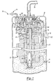
- Figure 1 is a sectional view of a compressor according to the present disclosure
- Figure 2 is a sectional view of the non-orbiting scroll end plate of the compressor of Figure 1 ;
- Figure 3 is a fragmentary sectional view of the compressor of Figure 1 including a valve arrangement
- Figure 4 is a perspective view of a valve member shown in the valve arrangement of Figure 3 ;
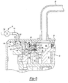
- Figure 5 is a fragmentary sectional view of the compressor of Figure 1 including an alternate valve arrangement
- Figure 6 is a fragmentary sectional view of the compressor of Figure 1 including an alternate valve arrangement.
- the present teachings are suitable for incorporation in many different types of scroll and rotary compressors, including hermetic machines, open drive machines and non-hermetic machines.
- a hermetic scroll refrigerant motor-compressor 10 of the low-side type i.e., where the motor and compressor are cooled by suction gas in the hermetic shell, as illustrated in the vertical section shown in Figure 1 , is described herein.
- compressor 10 may include a cylindrical hermetic shell 12, a compression mechanism 14, a main bearing housing 16, a motor assembly 18, a refrigerant discharge fitting 20, a suction gas inlet fitting 22, and a vapor injection system 24.
- the hermetic shell 12 may house the compression mechanism 14, main bearing housing 16, and motor assembly 18.
- Shell 12 may include an end cap 26 at the upper end thereof.
- the refrigerant discharge fitting 20 may be attached to shell 12 at opening 28 in end cap 26.
- the suction gas inlet fitting 22 may be attached to shell 12 at opening 30.
- the compression mechanism 14 may be driven by motor assembly 18 and supported by main bearing housing 16.
- the main bearing housing 16 may be affixed to shell 12 at a plurality of points in any desirable manner.
- the motor assembly 18 may generally include a motor 32, a frame 34 and a crankshaft 36.
- the motor 32 may include a motor stator 38 and a rotor 40.
- the motor stator 38 may be press fit into a frame 34, which may in turn be press fit into shell 12.
- Crankshaft 36 may be rotatably driven stator 38. Windings 42 may pass through stator 38.
- Rotor 40 may be press fit on crankshaft 36.
- a motor protector 44 may be provided in close proximity to windings 42 so that motor protector 44 will de-energize the motor 32 if the windings 42 exceed their normal temperature range.
- the crankshaft 36 may include an eccentric crank pin 46 and one or more counter-weights 48 at an upper end 50.
- Crankshaft 36 may be rotatably journaled in a first bearing 52 in main bearing housing 16 and in a second bearing 54 in frame 34.
- Crankshaft 36 may include an oil-pumping concentric bore 56 at a lower end 58.
- Concentric bore 56 may communicate with a radially outwardly inclined and relatively smaller diameter bore 60 extending to the upper end 50 of crankshaft 36.
- the lower portion of interior shell 12 may be filled with lubricating oil. Concentric bore 56 may provide pump action in conjunction with bore 60 to distribute lubricating fluid to various portions of compressor 10.
- Compression mechanism 14 may generally include an orbiting scroll 62 and a non-orbiting scroll 64.
- Orbiting scroll 62 may include an end plate 66 having a spiral vane or wrap 68 on the upper surface thereof and an annular flat thrust surface 70 on the lower surface.
- Thrust surface 70 may interface with an annular flat thrust bearing surface 72 on an upper surface of main bearing housing 16.
- a cylindrical hub 74 may project downwardly from thrust surface 70 and may include a journal bearing 76 having a drive bushing 78 rotatively disposed therein.
- Drive bushing 78 may include an inner bore in which crank pin 46 is drivingly disposed.
- Crank pin 46 may have a flat on one surface (not shown) that drivingly engages a flat surface in a portion of the inner bore of drive bushing 78 to provide a radially compliant driving arrangement, such as shown in assignee's U.S. Pat. No. 4,877,382 , the disclosure of which is herein incorporated by reference.
- Non-orbiting scroll 64 may include an end plate 80 having a non-orbiting spiral wrap 82 on the lower surface 84 thereof. Non-orbiting spiral wrap 82 may form a meshing engagement with wrap 68 of orbiting scroll 62, thereby creating an inlet pocket 86, intermediate pockets 88, 90, 92, 94, and outlet pocket 96. Non-orbiting scroll 64 may have a centrally disposed discharge passageway 98 in communication with outlet pocket 96 and upwardly open recess 100 which may be in fluid communication with discharge fitting 20.
- Non-orbiting scroll member 64 may include an annular recess 101 in the upper surface thereof having parallel coaxial side walls in which an annular floating seal 102 is sealingly disposed for relative axial movement.
- the bottom of recess 101 may be isolated from the presence of gas under suction and discharge pressure by floating seal 102 so that it can be placed in fluid communication with a source of intermediate fluid pressure by means of a passageway (not shown).
- the passageway may extend into an intermediate pocket 88, 90, 92, 94.
- Non-orbiting scroll member 64 may therefore be axially biased against orbiting scroll member 62 by the forces created by discharge pressure acting on the central portion of scroll member 64 and those created by intermediate fluid pressure acting on the bottom of recess 101.
- vapor injection passages 104a, 104b may be located within non-orbiting scroll end plate 80 and may be in communication with vapor injection system 24. Vapor injection passage 104a and 104b may be generally similar. Therefore, only vapor injection passage 104a will be described with the understanding that the description applies equally to vapor injection passage 104b.
- vapor injection passage 104a may include first and second portions 106, 108. First portion 106 may extend through sidewall 110 at opening 112 and generally radially into non-orbiting scroll 64. Opening 112 may form a recessed portion in sidewall 110 and may have a diameter greater than the diameter of first portion 106. Second portion 108 may intersect first portion 106 and extend through end plate lower surface 84, thereby providing communication between first portion 106 and intermediate pocket 92.
- Non-orbiting scroll 64 may be mounted to main bearing housing 16 in any manner that will provide limited axial movement of non-orbiting scroll member 64.
- non-orbiting scroll suspension system see assignee's U.S. Pat. No. 5,055,010 , the disclosure of which is hereby incorporated herein by reference.
- an Oldham coupling which may generally include a ring 103 having a first pair of keys 105 (one of which is shown) slidably disposed in diametrically opposed slots 107 (one of which is shown) in non-orbiting scroll 64 and a second pair of keys (not shown) slidably disposed in diametrically opposed slots in orbiting scroll 62.
- the vapor injection system 24 may include a vapor injection device 114, a top cap fitting 116, a scroll fitting 118, and a top cap seal 120.
- Vapor injection device 114 may be located external to shell 12 and may be in communication with scroll fitting 118 through top cap fitting 116.
- Top cap fitting 116 may be in the form of a flexible line and may pass through and be fixed to opening 126 in shell 12.
- Scroll fitting 118 may be in the form of a block fixed to sidewall 110 of non-orbiting scroll 64.
- Scroll fitting 118 may include an upper recessed portion 128 having top cap seal 120 disposed therein and engaged with end cap 26.
- Top cap seal 120 may provide sealed communication between top cap fitting 116 and scroll fitting 118, while allowing axial displacement of scroll fitting 118 relative to shell 12.
- Top cap seal 120 may be any of the seals noted above regarding seal 102.
- Scroll fitting 118 may include first and second passages 130, 132 therethrough.
- First passage 130 may extend generally longitudinally from upper recessed portion 128.
- Second passage 132 may intersect first passage 130 and extend generally radially through scroll fitting 118.
- Scroll fitting 118 may include a side recessed portion 134 near second passage 132.
- Side recessed portion 134 may have a diameter greater than the diameter of second passage 132 and generally surround vapor injection passage opening 112.
- An annular wall 133 may extend into side recessed portion 134, forming an annular recess 135 therebetween.
- First and second passages 130, 132 may therefore be in communication with vapor injection passage 104a, generally forming a vapor injection passageway therewith.
- vapor injection system 24 may include a valve 122.
- Valve 122 may include a valve member 136 and a spring 138.
- valve member 136 may be in the form of a disc having a diameter similar to the diameter of side recessed portion 134.
- Valve member 136 may include apertures 142 extending around a perimeter portion thereof.
- Valve member 136 may generally be divided into an inner diameter portion 137 and an outer diameter portion 139 by apertures 142.
- Spring 138 may be located between valve member 136 and non-orbiting scroll 64 to generally bias inner diameter portion 137 against annular wall 133 in a direction of flow from an interior portion to an exterior portion of non-orbiting scroll member 64, preventing flow from escaping past valve member 136, thereby reducing a dead volume between non-orbiting scroll 64 and vapor injection device 114.
- vapor injection system 24 may include a valve 124.
- Valve 124 may be located in non-orbiting scroll vapor injection passage 104a. More specifically, valve 124 may be located in vapor injection passage first portion 106.
- Valve 124 may include a housing 143 containing a valve seat 144, a ball 146, and a spring 148 therein. Housing 143 may have a first opening 145 allowing vapor from vapor injection device 114 to enter and a second set of openings 147 allowing the vapor to exit the housing and enter intermediate pocket 92.
- Seat 144 may be contained within housing 143 between first and second openings 145, 147.
- Valve 124 may be positioned near vapor injection passage second portion 108.
- Valve 124 may be arranged similar to valve 122, such that spring 148 may generally bias ball 146 against seat 144 in a direction of flow from an interior portion to an exterior portion of non-orbiting scroll member 64, thereby preventing flow from intermediate pocket 92 to vapor injection device 114 and reducing a dead volume between non-orbiting scroll 64 and vapor injection device 114.
- valve 124 has been described in passage 104a, it is understood that an additional valve 124 may be disposed in passage 104b as well.
- valve member 136 is urged to a closed position by the combination of spring 138 and flow from intermediate pocket 92.
- the flow from intermediate pocket 92 and spring 138 produce a force on a back side of valve member 136, and therefore bias valve member 136 in a direction of flow from an interior portion to an exterior portion of non-orbiting scroll member 64.
- intermediate pocket 92 varies with rotation of crankshaft 36. More specifically, during each rotation of crankshaft 36, the fluid pressurized within intermediate pocket 92 may vary over a range of pressures.
- fluid pressure in intermediate pocket 92 may vary between a first pressure and a second pressure and vapor injection device 114 may provide a fluid at an intermediate pressure between the first and second pressures.
- valve 122 When the fluid provided by vapor injection device 114 provides a force on a front side of valve member 136, valve 122 will move between opened and closed positions based on the difference between the force provided by the intermediate fluid pressure from vapor injection device 114 on the front side of valve member 136 and the combination of the biasing force of spring 138 and the variable force provided by fluid from intermediate pocket 92 on the back side of valve member 136.
- the difference in force provided by the first and second fluid pressures from intermediate pocket 92 during each rotation of crankshaft 36 allows valve 122 to open and close once per revolution of crankshaft 36.
Landscapes
- Engineering & Computer Science (AREA)
- Mechanical Engineering (AREA)
- General Engineering & Computer Science (AREA)
- Rotary Pumps (AREA)
- Applications Or Details Of Rotary Compressors (AREA)
Abstract
Description
- The present disclosure relates to compressors and more specifically to vapor injection systems for scroll compressors.
- Refrigerant compressors for cooling systems such as air conditioning, refrigeration or chiller systems, may include a vapor injection system to increase operating efficiency and capacity. During operation, passages between the vapor injection system and the compression mechanism may create dead volume that is compressed, consuming energy unnecessarily.
- A compressor may include a shell, a compression mechanism, a motor, and a vapor injection system. The compression mechanism may be contained within the shell and include a non-orbiting scroll axially displaceably mounted to the shell. The non-orbiting scroll may have an exterior portion, an interior portion, and a vapor injection passage extending therethrough from the exterior portion to the interior portion. The motor may be contained within the shell and may be drivingly coupled to the compression mechanism. The vapor injection system may include a vapor injection device, a vapor injection fitting, and a vapor injection valve. The vapor injection fitting may be in communication with the vapor injection device and the vapor injection passage. The vapor injection valve may be disposed between the shell and the interior of the non-orbiting scroll.
- Further areas of applicability will become apparent from the description provided herein. It should be understood that the description and specific examples are intended for purposes of illustration only and are not intended to limit the scope of the claims.
- The drawings described herein are for illustration purposes only and are not intended to limit the scope of the present disclosure in any way.
-
Figure 1 is a sectional view of a compressor according to the present disclosure; -
Figure 2 is a sectional view of the non-orbiting scroll end plate of the compressor ofFigure 1 ; -
Figure 3 is a fragmentary sectional view of the compressor ofFigure 1 including a valve arrangement; -
Figure 4 is a perspective view of a valve member shown in the valve arrangement ofFigure 3 ; -
Figure 5 is a fragmentary sectional view of the compressor ofFigure 1 including an alternate valve arrangement; and -
Figure 6 is a fragmentary sectional view of the compressor ofFigure 1 including an alternate valve arrangement. - The following description is merely exemplary in nature and is not intended to limit the present teachings, application, or uses.
- The present teachings are suitable for incorporation in many different types of scroll and rotary compressors, including hermetic machines, open drive machines and non-hermetic machines. For exemplary purposes, a hermetic scroll refrigerant motor-
compressor 10 of the low-side type, i.e., where the motor and compressor are cooled by suction gas in the hermetic shell, as illustrated in the vertical section shown inFigure 1 , is described herein. - With reference to
Figures 1 ,3 ,5 , and6 ,compressor 10 may include a cylindricalhermetic shell 12, a compression mechanism 14, a main bearinghousing 16, amotor assembly 18, a refrigerant discharge fitting 20, a suction gas inlet fitting 22, and avapor injection system 24. Thehermetic shell 12 may house the compression mechanism 14, main bearinghousing 16, andmotor assembly 18. Shell 12 may include anend cap 26 at the upper end thereof. The refrigerant discharge fitting 20 may be attached toshell 12 at opening 28 inend cap 26. The suction gas inlet fitting 22 may be attached toshell 12 at opening 30. The compression mechanism 14 may be driven bymotor assembly 18 and supported by main bearinghousing 16. The main bearinghousing 16 may be affixed to shell 12 at a plurality of points in any desirable manner. - The
motor assembly 18 may generally include amotor 32, aframe 34 and acrankshaft 36. Themotor 32 may include a motor stator 38 and arotor 40. The motor stator 38 may be press fit into aframe 34, which may in turn be press fit intoshell 12.Crankshaft 36 may be rotatably driven stator 38.Windings 42 may pass through stator 38.Rotor 40 may be press fit oncrankshaft 36. Amotor protector 44 may be provided in close proximity towindings 42 so thatmotor protector 44 will de-energize themotor 32 if thewindings 42 exceed their normal temperature range. - The
crankshaft 36 may include aneccentric crank pin 46 and one ormore counter-weights 48 at an upper end 50.Crankshaft 36 may be rotatably journaled in a first bearing 52 in main bearinghousing 16 and in a second bearing 54 inframe 34.Crankshaft 36 may include an oil-pumping concentric bore 56 at alower end 58. Concentric bore 56 may communicate with a radially outwardly inclined and relativelysmaller diameter bore 60 extending to the upper end 50 ofcrankshaft 36. The lower portion ofinterior shell 12 may be filled with lubricating oil. Concentric bore 56 may provide pump action in conjunction withbore 60 to distribute lubricating fluid to various portions ofcompressor 10. - Compression mechanism 14 may generally include an
orbiting scroll 62 and a non-orbiting scroll 64.Orbiting scroll 62 may include anend plate 66 having a spiral vane orwrap 68 on the upper surface thereof and an annularflat thrust surface 70 on the lower surface.Thrust surface 70 may interface with an annular flat thrust bearing surface 72 on an upper surface of main bearinghousing 16. Acylindrical hub 74 may project downwardly fromthrust surface 70 and may include a journal bearing 76 having a drive bushing 78 rotatively disposed therein. Drive bushing 78 may include an inner bore in whichcrank pin 46 is drivingly disposed.Crank pin 46 may have a flat on one surface (not shown) that drivingly engages a flat surface in a portion of the inner bore of drive bushing 78 to provide a radially compliant driving arrangement, such as shown in assignee'sU.S. Pat. No. 4,877,382 , the disclosure of which is herein incorporated by reference. - Non-orbiting scroll 64 may include an
end plate 80 having a non-orbiting spiral wrap 82 on the lower surface 84 thereof. Non-orbiting spiral wrap 82 may form a meshing engagement withwrap 68 of orbitingscroll 62, thereby creating an inlet pocket 86,intermediate pockets outlet pocket 96. Non-orbiting scroll 64 may have a centrally disposeddischarge passageway 98 in communication withoutlet pocket 96 and upwardlyopen recess 100 which may be in fluid communication with discharge fitting 20. - Non-orbiting scroll member 64 may include an
annular recess 101 in the upper surface thereof having parallel coaxial side walls in which an annularfloating seal 102 is sealingly disposed for relative axial movement. The bottom ofrecess 101 may be isolated from the presence of gas under suction and discharge pressure by floatingseal 102 so that it can be placed in fluid communication with a source of intermediate fluid pressure by means of a passageway (not shown). The passageway may extend into anintermediate pocket scroll member 62 by the forces created by discharge pressure acting on the central portion of scroll member 64 and those created by intermediate fluid pressure acting on the bottom ofrecess 101. - With additional reference to
Figure 2 ,vapor injection passages scroll end plate 80 and may be in communication withvapor injection system 24.Vapor injection passage vapor injection passage 104a will be described with the understanding that the description applies equally tovapor injection passage 104b. As seen inFigures 3 ,5 , and6 ,vapor injection passage 104a may include first andsecond portions First portion 106 may extend throughsidewall 110 at opening 112 and generally radially into non-orbiting scroll 64. Opening 112 may form a recessed portion insidewall 110 and may have a diameter greater than the diameter offirst portion 106.Second portion 108 may intersectfirst portion 106 and extend through end plate lower surface 84, thereby providing communication betweenfirst portion 106 andintermediate pocket 92. - Non-orbiting scroll 64 may be mounted to
main bearing housing 16 in any manner that will provide limited axial movement of non-orbiting scroll member 64. For a more detailed description of the non-orbiting scroll suspension system, see assignee'sU.S. Pat. No. 5,055,010 , the disclosure of which is hereby incorporated herein by reference. - Relative rotation of the
scroll members 62, 64 may be prevented by an Oldham coupling, which may generally include aring 103 having a first pair of keys 105 (one of which is shown) slidably disposed in diametrically opposed slots 107 (one of which is shown) in non-orbiting scroll 64 and a second pair of keys (not shown) slidably disposed in diametrically opposed slots in orbitingscroll 62. - The
vapor injection system 24 may include avapor injection device 114, a top cap fitting 116, a scroll fitting 118, and atop cap seal 120.Vapor injection device 114 may be located external to shell 12 and may be in communication with scroll fitting 118 through top cap fitting 116. Top cap fitting 116 may be in the form of a flexible line and may pass through and be fixed to opening 126 inshell 12. - Scroll fitting 118 may be in the form of a block fixed to
sidewall 110 of non-orbiting scroll 64. Scroll fitting 118 may include an upper recessedportion 128 havingtop cap seal 120 disposed therein and engaged withend cap 26.Top cap seal 120 may provide sealed communication between top cap fitting 116 and scroll fitting 118, while allowing axial displacement of scroll fitting 118 relative to shell 12.Top cap seal 120 may be any of the seals noted above regardingseal 102. - Scroll fitting 118 may include first and
second passages First passage 130 may extend generally longitudinally from upper recessedportion 128.Second passage 132 may intersectfirst passage 130 and extend generally radially through scroll fitting 118. Scroll fitting 118 may include a side recessedportion 134 nearsecond passage 132. Side recessedportion 134 may have a diameter greater than the diameter ofsecond passage 132 and generally surround vaporinjection passage opening 112. Anannular wall 133 may extend into side recessedportion 134, forming anannular recess 135 therebetween. First andsecond passages vapor injection passage 104a, generally forming a vapor injection passageway therewith. - With reference to
Figure 3 ,vapor injection system 24 may include avalve 122.Valve 122 may include avalve member 136 and aspring 138. With additional reference toFigure 4 ,valve member 136 may be in the form of a disc having a diameter similar to the diameter of side recessedportion 134.Valve member 136 may includeapertures 142 extending around a perimeter portion thereof.Valve member 136 may generally be divided into aninner diameter portion 137 and anouter diameter portion 139 byapertures 142.Spring 138 may be located betweenvalve member 136 and non-orbiting scroll 64 to generally biasinner diameter portion 137 againstannular wall 133 in a direction of flow from an interior portion to an exterior portion of non-orbiting scroll member 64, preventing flow from escapingpast valve member 136, thereby reducing a dead volume between non-orbiting scroll 64 andvapor injection device 114. - With reference to
Figure 5 ,vapor injection system 24 may include avalve 124.Valve 124 may be located in non-orbiting scrollvapor injection passage 104a. More specifically,valve 124 may be located in vapor injection passagefirst portion 106.Valve 124 may include ahousing 143 containing a valve seat 144, aball 146, and aspring 148 therein.Housing 143 may have afirst opening 145 allowing vapor fromvapor injection device 114 to enter and a second set ofopenings 147 allowing the vapor to exit the housing and enterintermediate pocket 92. Seat 144 may be contained withinhousing 143 between first andsecond openings Valve 124 may be positioned near vapor injection passagesecond portion 108.Valve 124 may be arranged similar tovalve 122, such thatspring 148 may generally biasball 146 against seat 144 in a direction of flow from an interior portion to an exterior portion of non-orbiting scroll member 64, thereby preventing flow fromintermediate pocket 92 tovapor injection device 114 and reducing a dead volume between non-orbiting scroll 64 andvapor injection device 114. - Alternately, as seen in
Figure 6 ,ball 146 may be replaced with apiston 150. Whilevalve 124 has been described inpassage 104a, it is understood that anadditional valve 124 may be disposed inpassage 104b as well. - Operation of
valve 122 will now be discussed with the understanding that the description applies equally tovalve 124. As indicated above,valve member 136 is urged to a closed position by the combination ofspring 138 and flow fromintermediate pocket 92. The flow fromintermediate pocket 92 andspring 138 produce a force on a back side ofvalve member 136, and therefore biasvalve member 136 in a direction of flow from an interior portion to an exterior portion of non-orbiting scroll member 64. - During compressor operation, the pressure of the fluid within
intermediate pocket 92 varies with rotation ofcrankshaft 36. More specifically, during each rotation ofcrankshaft 36, the fluid pressurized withinintermediate pocket 92 may vary over a range of pressures. For exemplary purposes, fluid pressure inintermediate pocket 92 may vary between a first pressure and a second pressure andvapor injection device 114 may provide a fluid at an intermediate pressure between the first and second pressures. When the fluid provided byvapor injection device 114 provides a force on a front side ofvalve member 136,valve 122 will move between opened and closed positions based on the difference between the force provided by the intermediate fluid pressure fromvapor injection device 114 on the front side ofvalve member 136 and the combination of the biasing force ofspring 138 and the variable force provided by fluid fromintermediate pocket 92 on the back side ofvalve member 136. The difference in force provided by the first and second fluid pressures fromintermediate pocket 92 during each rotation ofcrankshaft 36 allowsvalve 122 to open and close once per revolution ofcrankshaft 36.
Claims (25)
Applications Claiming Priority (1)
| Application Number | Priority Date | Filing Date | Title |
|---|---|---|---|
| US11/645,288 US7771178B2 (en) | 2006-12-22 | 2006-12-22 | Vapor injection system for a scroll compressor |
Publications (1)
| Publication Number | Publication Date |
|---|---|
| EP1936197A1 true EP1936197A1 (en) | 2008-06-25 |
Family
ID=39148651
Family Applications (1)
| Application Number | Title | Priority Date | Filing Date |
|---|---|---|---|
| EP07254962A Withdrawn EP1936197A1 (en) | 2006-12-22 | 2007-12-19 | Scroll compressor with vapor injection system |
Country Status (3)
| Country | Link |
|---|---|
| US (1) | US7771178B2 (en) |
| EP (1) | EP1936197A1 (en) |
| CN (1) | CN101205916B (en) |
Cited By (4)
| Publication number | Priority date | Publication date | Assignee | Title |
|---|---|---|---|---|
| WO2013145713A1 (en) * | 2012-03-30 | 2013-10-03 | 株式会社デンソー | Compressor |
| WO2015033550A1 (en) * | 2013-09-09 | 2015-03-12 | 株式会社デンソー | Compressor |
| EP2644892A3 (en) * | 2012-03-30 | 2016-03-02 | Kabushiki Kaisha Toyota Jidoshokki | Scroll compressor |
| EP3477113A4 (en) * | 2016-06-28 | 2019-05-01 | Mitsubishi Electric Corporation | SPIRAL COMPRESSOR |
Families Citing this family (44)
| Publication number | Priority date | Publication date | Assignee | Title |
|---|---|---|---|---|
| US7815423B2 (en) * | 2005-07-29 | 2010-10-19 | Emerson Climate Technologies, Inc. | Compressor with fluid injection system |
| CN100386522C (en) * | 2006-05-22 | 2008-05-07 | 南京奥特佳冷机有限公司 | Constant pressure hermetic scroll compressor for vehicle |
| JP4965423B2 (en) * | 2007-12-28 | 2012-07-04 | 株式会社日立産機システム | Compression device |
| US7976295B2 (en) | 2008-05-30 | 2011-07-12 | Emerson Climate Technologies, Inc. | Compressor having capacity modulation system |
| CN102418698B (en) | 2008-05-30 | 2014-12-10 | 艾默生环境优化技术有限公司 | Compressor having output adjustment assembly including piston actuation |
| KR101280915B1 (en) * | 2008-05-30 | 2013-07-02 | 에머슨 클리메이트 테크놀로지즈 인코퍼레이티드 | Compressor having capacity modulation system |
| CA2671109C (en) * | 2008-07-08 | 2012-10-23 | Tecumseh Products Company | Scroll compressor utilizing liquid or vapor injection |
| US7988433B2 (en) | 2009-04-07 | 2011-08-02 | Emerson Climate Technologies, Inc. | Compressor having capacity modulation assembly |
| US8616014B2 (en) | 2009-05-29 | 2013-12-31 | Emerson Climate Technologies, Inc. | Compressor having capacity modulation or fluid injection systems |
| US8568118B2 (en) * | 2009-05-29 | 2013-10-29 | Emerson Climate Technologies, Inc. | Compressor having piston assembly |
| US9651043B2 (en) | 2012-11-15 | 2017-05-16 | Emerson Climate Technologies, Inc. | Compressor valve system and assembly |
| US9249802B2 (en) | 2012-11-15 | 2016-02-02 | Emerson Climate Technologies, Inc. | Compressor |
| US9435340B2 (en) | 2012-11-30 | 2016-09-06 | Emerson Climate Technologies, Inc. | Scroll compressor with variable volume ratio port in orbiting scroll |
| US9127677B2 (en) | 2012-11-30 | 2015-09-08 | Emerson Climate Technologies, Inc. | Compressor with capacity modulation and variable volume ratio |
| EP2806165B1 (en) * | 2013-05-22 | 2015-09-09 | Obrist Engineering GmbH | Scroll compressor and CO2 vehicle air conditioner with a scroll compressor |
| JP6253278B2 (en) * | 2013-07-03 | 2017-12-27 | 日立ジョンソンコントロールズ空調株式会社 | Refrigeration cycle |
| US9739277B2 (en) | 2014-05-15 | 2017-08-22 | Emerson Climate Technologies, Inc. | Capacity-modulated scroll compressor |
| US9989057B2 (en) | 2014-06-03 | 2018-06-05 | Emerson Climate Technologies, Inc. | Variable volume ratio scroll compressor |
| JP6355453B2 (en) * | 2014-06-27 | 2018-07-11 | 三菱電機株式会社 | Scroll compressor |
| JP6379959B2 (en) * | 2014-10-07 | 2018-08-29 | 株式会社デンソー | Refrigeration cycle compressor |
| JP6470697B2 (en) * | 2015-02-27 | 2019-02-13 | ダイキン工業株式会社 | Compressor |
| US9790940B2 (en) | 2015-03-19 | 2017-10-17 | Emerson Climate Technologies, Inc. | Variable volume ratio compressor |
| US10378540B2 (en) | 2015-07-01 | 2019-08-13 | Emerson Climate Technologies, Inc. | Compressor with thermally-responsive modulation system |
| US10598180B2 (en) | 2015-07-01 | 2020-03-24 | Emerson Climate Technologies, Inc. | Compressor with thermally-responsive injector |
| US10378542B2 (en) | 2015-07-01 | 2019-08-13 | Emerson Climate Technologies, Inc. | Compressor with thermal protection system |
| CN207377799U (en) | 2015-10-29 | 2018-05-18 | 艾默生环境优化技术有限公司 | Compressor |
| US10801495B2 (en) | 2016-09-08 | 2020-10-13 | Emerson Climate Technologies, Inc. | Oil flow through the bearings of a scroll compressor |
| US10890186B2 (en) | 2016-09-08 | 2021-01-12 | Emerson Climate Technologies, Inc. | Compressor |
| US10753352B2 (en) | 2017-02-07 | 2020-08-25 | Emerson Climate Technologies, Inc. | Compressor discharge valve assembly |
| CN110268161B (en) * | 2017-02-17 | 2020-10-20 | 三菱电机株式会社 | scroll compressor |
| US11022119B2 (en) | 2017-10-03 | 2021-06-01 | Emerson Climate Technologies, Inc. | Variable volume ratio compressor |
| US10962008B2 (en) | 2017-12-15 | 2021-03-30 | Emerson Climate Technologies, Inc. | Variable volume ratio compressor |
| US10995753B2 (en) | 2018-05-17 | 2021-05-04 | Emerson Climate Technologies, Inc. | Compressor having capacity modulation assembly |
| US11656003B2 (en) | 2019-03-11 | 2023-05-23 | Emerson Climate Technologies, Inc. | Climate-control system having valve assembly |
| WO2021038738A1 (en) * | 2019-08-28 | 2021-03-04 | 三菱電機株式会社 | Scroll compressor |
| CN113389723B (en) * | 2020-03-13 | 2025-07-11 | 谷轮环境科技(苏州)有限公司 | Scroll compressor |
| CN114688031B (en) | 2020-12-29 | 2025-01-24 | 丹佛斯(天津)有限公司 | Compressor and method for controlling the same |
| US11655813B2 (en) | 2021-07-29 | 2023-05-23 | Emerson Climate Technologies, Inc. | Compressor modulation system with multi-way valve |
| US12259163B2 (en) | 2022-06-01 | 2025-03-25 | Copeland Lp | Climate-control system with thermal storage |
| US11846287B1 (en) | 2022-08-11 | 2023-12-19 | Copeland Lp | Scroll compressor with center hub |
| US11965507B1 (en) | 2022-12-15 | 2024-04-23 | Copeland Lp | Compressor and valve assembly |
| US12416308B2 (en) | 2022-12-28 | 2025-09-16 | Copeland Lp | Compressor with shutdown assembly |
| US12173708B1 (en) | 2023-12-07 | 2024-12-24 | Copeland Lp | Heat pump systems with capacity modulation |
| US12163523B1 (en) | 2023-12-15 | 2024-12-10 | Copeland Lp | Compressor and valve assembly |
Citations (8)
| Publication number | Priority date | Publication date | Assignee | Title |
|---|---|---|---|---|
| US4475360A (en) * | 1982-02-26 | 1984-10-09 | Hitachi, Ltd. | Refrigeration system incorporating scroll type compressor |
| JPH11107950A (en) * | 1997-10-06 | 1999-04-20 | Matsushita Electric Ind Co Ltd | Compressor injection device |
| US6202438B1 (en) * | 1999-11-23 | 2001-03-20 | Scroll Technologies | Compressor economizer circuit with check valve |
| US6293776B1 (en) * | 2000-07-12 | 2001-09-25 | Scroll Technologies | Method of connecting an economizer tube |
| EP1182353A1 (en) * | 2000-08-15 | 2002-02-27 | Copeland Corporation | Scroll machine |
| EP1382854A2 (en) * | 2002-07-15 | 2004-01-21 | Copeland Corporation | Dual volume-ratio scroll machine |
| US20040184932A1 (en) | 2003-03-17 | 2004-09-23 | Alexander Lifson | Economizer/by-pass port inserts to control port size |
| WO2007046810A2 (en) * | 2005-10-20 | 2007-04-26 | Carrier Corporation | Economized refrigerant system with vapor injection at low pressure |
Family Cites Families (21)
| Publication number | Priority date | Publication date | Assignee | Title |
|---|---|---|---|---|
| US4058988A (en) * | 1976-01-29 | 1977-11-22 | Dunham-Bush, Inc. | Heat pump system with high efficiency reversible helical screw rotary compressor |
| JPS5481513A (en) * | 1977-12-09 | 1979-06-29 | Hitachi Ltd | Scroll compressor |
| US4545742A (en) * | 1982-09-30 | 1985-10-08 | Dunham-Bush, Inc. | Vertical axis hermetic helical screw rotary compressor with discharge gas oil mist eliminator and dual transfer tube manifold for supplying liquid refrigerant and refrigerant vapor to the compression area |
| JPS60259794A (en) * | 1984-06-04 | 1985-12-21 | Hitachi Ltd | Heat pump type air conditioner |
| US4609329A (en) * | 1985-04-05 | 1986-09-02 | Frick Company | Micro-processor control of a movable slide stop and a movable slide valve in a helical screw rotary compressor with an enconomizer inlet port |
| JPS61265381A (en) * | 1985-05-20 | 1986-11-25 | Hitachi Ltd | Gas injector for screw compressor |
| JPH0641756B2 (en) * | 1985-06-18 | 1994-06-01 | サンデン株式会社 | Variable capacity scroll type compressor |
| US4877382A (en) * | 1986-08-22 | 1989-10-31 | Copeland Corporation | Scroll-type machine with axially compliant mounting |
| US5055010A (en) * | 1990-10-01 | 1991-10-08 | Copeland Corporation | Suction baffle for refrigeration compressor |
| JPH04117195U (en) * | 1991-04-02 | 1992-10-20 | サンデン株式会社 | scroll compressor |
| JP3376729B2 (en) * | 1994-06-08 | 2003-02-10 | 株式会社日本自動車部品総合研究所 | Scroll compressor |
| US5640854A (en) * | 1995-06-07 | 1997-06-24 | Copeland Corporation | Scroll machine having liquid injection controlled by internal valve |
| US5722257A (en) * | 1995-10-11 | 1998-03-03 | Denso Corporation | Compressor having refrigerant injection ports |
| JP3591101B2 (en) * | 1995-12-19 | 2004-11-17 | ダイキン工業株式会社 | Scroll type fluid machine |
| US6095765A (en) * | 1998-03-05 | 2000-08-01 | Carrier Corporation | Combined pressure ratio and pressure differential relief valve |
| US6213731B1 (en) * | 1999-09-21 | 2001-04-10 | Copeland Corporation | Compressor pulse width modulation |
| JP2003074482A (en) * | 2001-08-31 | 2003-03-12 | Sanyo Electric Co Ltd | Scroll compressor |
| US6619936B2 (en) * | 2002-01-16 | 2003-09-16 | Copeland Corporation | Scroll compressor with vapor injection |
| KR100434077B1 (en) * | 2002-05-01 | 2004-06-04 | 엘지전자 주식회사 | Apparatus preventing vacuum for scroll compressor |
| KR100498309B1 (en) * | 2002-12-13 | 2005-07-01 | 엘지전자 주식회사 | High-degree vacuum prevention apparatus for scroll compressor and assembly method for this apparatus |
| JP4722493B2 (en) * | 2004-03-24 | 2011-07-13 | 株式会社日本自動車部品総合研究所 | Fluid machinery |
-
2006
- 2006-12-22 US US11/645,288 patent/US7771178B2/en active Active
-
2007
- 2007-12-19 EP EP07254962A patent/EP1936197A1/en not_active Withdrawn
- 2007-12-21 CN CN2007101600385A patent/CN101205916B/en active Active
Patent Citations (8)
| Publication number | Priority date | Publication date | Assignee | Title |
|---|---|---|---|---|
| US4475360A (en) * | 1982-02-26 | 1984-10-09 | Hitachi, Ltd. | Refrigeration system incorporating scroll type compressor |
| JPH11107950A (en) * | 1997-10-06 | 1999-04-20 | Matsushita Electric Ind Co Ltd | Compressor injection device |
| US6202438B1 (en) * | 1999-11-23 | 2001-03-20 | Scroll Technologies | Compressor economizer circuit with check valve |
| US6293776B1 (en) * | 2000-07-12 | 2001-09-25 | Scroll Technologies | Method of connecting an economizer tube |
| EP1182353A1 (en) * | 2000-08-15 | 2002-02-27 | Copeland Corporation | Scroll machine |
| EP1382854A2 (en) * | 2002-07-15 | 2004-01-21 | Copeland Corporation | Dual volume-ratio scroll machine |
| US20040184932A1 (en) | 2003-03-17 | 2004-09-23 | Alexander Lifson | Economizer/by-pass port inserts to control port size |
| WO2007046810A2 (en) * | 2005-10-20 | 2007-04-26 | Carrier Corporation | Economized refrigerant system with vapor injection at low pressure |
Cited By (7)
| Publication number | Priority date | Publication date | Assignee | Title |
|---|---|---|---|---|
| WO2013145713A1 (en) * | 2012-03-30 | 2013-10-03 | 株式会社デンソー | Compressor |
| JP2013209954A (en) * | 2012-03-30 | 2013-10-10 | Nippon Soken Inc | Injection device for compressor |
| EP2644892A3 (en) * | 2012-03-30 | 2016-03-02 | Kabushiki Kaisha Toyota Jidoshokki | Scroll compressor |
| US9765780B2 (en) | 2012-03-30 | 2017-09-19 | Denso Corporation | Compressor |
| WO2015033550A1 (en) * | 2013-09-09 | 2015-03-12 | 株式会社デンソー | Compressor |
| JP2015052306A (en) * | 2013-09-09 | 2015-03-19 | 株式会社日本自動車部品総合研究所 | Compressor |
| EP3477113A4 (en) * | 2016-06-28 | 2019-05-01 | Mitsubishi Electric Corporation | SPIRAL COMPRESSOR |
Also Published As
| Publication number | Publication date |
|---|---|
| US20080152526A1 (en) | 2008-06-26 |
| CN101205916A (en) | 2008-06-25 |
| US7771178B2 (en) | 2010-08-10 |
| CN101205916B (en) | 2013-12-11 |
Similar Documents
| Publication | Publication Date | Title |
|---|---|---|
| US7771178B2 (en) | Vapor injection system for a scroll compressor | |
| US6773242B1 (en) | Scroll compressor with vapor injection | |
| KR102043808B1 (en) | Co-rotating compressor | |
| US6537043B1 (en) | Compressor discharge valve having a contoured body with a uniform thickness | |
| US7896629B2 (en) | Scroll compressor with discharge valve | |
| US7547202B2 (en) | Scroll compressor with capacity modulation | |
| US6350111B1 (en) | Scroll machine with ported orbiting scroll member | |
| US6179589B1 (en) | Scroll machine with discus discharge valve | |
| US9494157B2 (en) | Compressor with capacity modulation and variable volume ratio | |
| US7568897B2 (en) | Scroll machine with seal | |
| US8043078B2 (en) | Compressor sealing arrangement | |
| US6264446B1 (en) | Horizontal scroll compressor | |
| US7959421B2 (en) | Compressor having a shutdown valve | |
| US6139291A (en) | Scroll machine with discharge valve | |
| KR102408562B1 (en) | Scroll compressor | |
| US8888475B2 (en) | Scroll compressor with oil supply across a sealing part | |
| US7997883B2 (en) | Scroll compressor with scroll deflection compensation | |
| US20090116977A1 (en) | Compressor With Muffler |
Legal Events
| Date | Code | Title | Description |
|---|---|---|---|
| PUAI | Public reference made under article 153(3) epc to a published international application that has entered the european phase |
Free format text: ORIGINAL CODE: 0009012 |
|
| AK | Designated contracting states |
Kind code of ref document: A1 Designated state(s): AT BE BG CH CY CZ DE DK EE ES FI FR GB GR HU IE IS IT LI LT LU LV MC MT NL PL PT RO SE SI SK TR |
|
| AX | Request for extension of the european patent |
Extension state: AL BA HR MK RS |
|
| 17P | Request for examination filed |
Effective date: 20081219 |
|
| AKX | Designation fees paid |
Designated state(s): DE FR |
|
| 17Q | First examination report despatched |
Effective date: 20090303 |
|
| RAP1 | Party data changed (applicant data changed or rights of an application transferred) |
Owner name: EMERSON CLIMATE TECHNOLOGIES, INC. |
|
| STAA | Information on the status of an ep patent application or granted ep patent |
Free format text: STATUS: THE APPLICATION IS DEEMED TO BE WITHDRAWN |
|
| 18D | Application deemed to be withdrawn |
Effective date: 20150519 |