EP1936184A2 - Ice detection based on anemometry - Google Patents
Ice detection based on anemometry Download PDFInfo
- Publication number
- EP1936184A2 EP1936184A2 EP07122650A EP07122650A EP1936184A2 EP 1936184 A2 EP1936184 A2 EP 1936184A2 EP 07122650 A EP07122650 A EP 07122650A EP 07122650 A EP07122650 A EP 07122650A EP 1936184 A2 EP1936184 A2 EP 1936184A2
- Authority
- EP
- European Patent Office
- Prior art keywords
- anemometer
- icing
- type
- ice
- occur
- Prior art date
- Legal status (The legal status is an assumption and is not a legal conclusion. Google has not performed a legal analysis and makes no representation as to the accuracy of the status listed.)
- Granted
Links
Images



Classifications
-
- F—MECHANICAL ENGINEERING; LIGHTING; HEATING; WEAPONS; BLASTING
- F03—MACHINES OR ENGINES FOR LIQUIDS; WIND, SPRING, OR WEIGHT MOTORS; PRODUCING MECHANICAL POWER OR A REACTIVE PROPULSIVE THRUST, NOT OTHERWISE PROVIDED FOR
- F03D—WIND MOTORS
- F03D80/00—Details, components or accessories not provided for in groups F03D1/00 - F03D17/00
- F03D80/40—Ice detection; De-icing means
-
- F—MECHANICAL ENGINEERING; LIGHTING; HEATING; WEAPONS; BLASTING
- F05—INDEXING SCHEMES RELATING TO ENGINES OR PUMPS IN VARIOUS SUBCLASSES OF CLASSES F01-F04
- F05B—INDEXING SCHEME RELATING TO WIND, SPRING, WEIGHT, INERTIA OR LIKE MOTORS, TO MACHINES OR ENGINES FOR LIQUIDS COVERED BY SUBCLASSES F03B, F03D AND F03G
- F05B2260/00—Function
- F05B2260/80—Diagnostics
-
- F—MECHANICAL ENGINEERING; LIGHTING; HEATING; WEAPONS; BLASTING
- F05—INDEXING SCHEMES RELATING TO ENGINES OR PUMPS IN VARIOUS SUBCLASSES OF CLASSES F01-F04
- F05B—INDEXING SCHEME RELATING TO WIND, SPRING, WEIGHT, INERTIA OR LIKE MOTORS, TO MACHINES OR ENGINES FOR LIQUIDS COVERED BY SUBCLASSES F03B, F03D AND F03G
- F05B2260/00—Function
- F05B2260/845—Redundancy
-
- F—MECHANICAL ENGINEERING; LIGHTING; HEATING; WEAPONS; BLASTING
- F05—INDEXING SCHEMES RELATING TO ENGINES OR PUMPS IN VARIOUS SUBCLASSES OF CLASSES F01-F04
- F05B—INDEXING SCHEME RELATING TO WIND, SPRING, WEIGHT, INERTIA OR LIKE MOTORS, TO MACHINES OR ENGINES FOR LIQUIDS COVERED BY SUBCLASSES F03B, F03D AND F03G
- F05B2270/00—Control
- F05B2270/40—Type of control system
- F05B2270/404—Type of control system active, predictive, or anticipative
-
- F—MECHANICAL ENGINEERING; LIGHTING; HEATING; WEAPONS; BLASTING
- F05—INDEXING SCHEMES RELATING TO ENGINES OR PUMPS IN VARIOUS SUBCLASSES OF CLASSES F01-F04
- F05B—INDEXING SCHEME RELATING TO WIND, SPRING, WEIGHT, INERTIA OR LIKE MOTORS, TO MACHINES OR ENGINES FOR LIQUIDS COVERED BY SUBCLASSES F03B, F03D AND F03G
- F05B2270/00—Control
- F05B2270/80—Devices generating input signals, e.g. transducers, sensors, cameras or strain gauges
-
- F—MECHANICAL ENGINEERING; LIGHTING; HEATING; WEAPONS; BLASTING
- F05—INDEXING SCHEMES RELATING TO ENGINES OR PUMPS IN VARIOUS SUBCLASSES OF CLASSES F01-F04
- F05B—INDEXING SCHEME RELATING TO WIND, SPRING, WEIGHT, INERTIA OR LIKE MOTORS, TO MACHINES OR ENGINES FOR LIQUIDS COVERED BY SUBCLASSES F03B, F03D AND F03G
- F05B2270/00—Control
- F05B2270/80—Devices generating input signals, e.g. transducers, sensors, cameras or strain gauges
- F05B2270/802—Calibration thereof
-
- Y—GENERAL TAGGING OF NEW TECHNOLOGICAL DEVELOPMENTS; GENERAL TAGGING OF CROSS-SECTIONAL TECHNOLOGIES SPANNING OVER SEVERAL SECTIONS OF THE IPC; TECHNICAL SUBJECTS COVERED BY FORMER USPC CROSS-REFERENCE ART COLLECTIONS [XRACs] AND DIGESTS
- Y02—TECHNOLOGIES OR APPLICATIONS FOR MITIGATION OR ADAPTATION AGAINST CLIMATE CHANGE
- Y02E—REDUCTION OF GREENHOUSE GAS [GHG] EMISSIONS, RELATED TO ENERGY GENERATION, TRANSMISSION OR DISTRIBUTION
- Y02E10/00—Energy generation through renewable energy sources
- Y02E10/70—Wind energy
- Y02E10/72—Wind turbines with rotation axis in wind direction
Definitions
- the present invention relates to icing of wind turbines. More particularly, the invention relates to ice detection for wind turbines and an ice detection unit. Specifically, the invention relates to a method for ice detection for a wind turbine, a method for calibrating an ice detection unit, and an ice detection unit for a wind turbine.
- a method for ice detection includes providing an ice condition threshold parameter adapted for distinguishing a condition during which icing may occur and a condition during which icing may not occur, measuring a wind velocity with a first anemometer, wherein the first anemometer being of a first type, measuring a wind velocity with a second anemometer, wherein the second anemometer being of a second type, and wherein the second type is different from the first type, evaluating, for a condition during which icing may occur, a deviation of the wind velocity measured with the first anemometer and the wind velocity measured with the second anemometer, and determine whether the deviation exceeds a limit value based on a calibration conducted under a condition during which icing may not occur.
- a method for calibrating an ice detection unit includes measuring a data set of a first anemometer for a period and under a condition during which icing may not occur, wherein the first anemometer being of a first type, measuring a data set of a second anemometer corresponding to the period, wherein the second anemometer being of a second type, and wherein the second type is different from the first type, defining a functional interrelation between the first data set and the second data set, and defining a limit value determining a deviation threshold to indicate an icing condition flag.
- an ice detection unit includes a first anemometer of a first type, a second anemometer of a second type, wherein the second type is different from the first type and wherein the second anemometer is heatable to reduce affection of the second anemometer by ice, a temperature sensor adapted for measuring an ice condition threshold parameter to distinguish a condition during which icing may occur and a condition during which icing may not occur, and an evaluation unit adapted for evaluating a functional relationship between a signal from the first anemometer and the second anemometer.
- ice will develop on the turbine components, for example, the anemometers and the blades.
- the commonly used ice sensor does not provide sufficient accuracy.
- the inability to detect ice with a desired accuracy may lead to ice-throw from the turbine blades and, as a result, the wind turbine may need to be shut down below a certain temperature.
- Figure 1 illustrates an embodiment wherein the system for ice detection is provided on a wind turbine 100.
- a nacelle 6 is provided on top of the tower 2.
- the hub 4 is rotatably held at the nacelle 6.
- the rotor blades 8 are mounted to the nacelle 6.
- the system for ice detection includes two anemometers 110 and 120. As indicated by the different sizes of the anemometers, two different types of anemometers are provided on the nacelle 6.
- the first anemometer 110 is more easily affected by icing.
- the second anemometer 120 is less affected by icing.
- the signals received by the two anemometers 110 and 120 are evaluated in order to signal icing conditions.
- a detection unit for an ice condition parameter value 130 may be provided.
- the anemometers 110 and 120 and the detection unit 130 are connected to an evaluation unit.
- the detection unit 130 is a temperature sensor known in the art. The temperature sensor measures the temperature and determines whether the temperature is below or above a threshold value.
- the evaluation unit 140 receives signals from the first and second anemometer and the temperature sensor. As described with respect to Figs. 2 to 4 below, the evaluation unit is adapted to provide a functional relationship between measurement values of the first anemometer and the second anemometer. Generally, by comparing the signal of the anemometer 120 and the signal of the anemometer 110, an ice detection signal can be generated.
- the anemometer 120 is a heated sonic anemometer that does not ice easily.
- the anemometer 110 is a cup anemometer, which is more likely affected by icing. Therefore, on occurrence of icing at the nacelle in particularly the second anemometer 110 is affected by icing.
- the signals of the first anemometer 120 and the signals of the second anemometer 110 will indicate a difference in wind velocity. The differences will be described in more detail with regard to the methods illustrated in Figs. 2 to 4 and the anemometers illustrated in Figs. 5 and 6 .
- FIG. 2 shows a flowchart illustrating a method conducted for an ice detection system.
- the method starts at step 210, wherein the system is initialized and, for example, predetermined parameter values are read from a memory, predetermined parameter values are provided by a user interface, or the like.
- a measured ice condition value is compared to an ice condition threshold parameter.
- the ice condition threshold parameter is a temperature value. For example, if the temperature is measured with a temperature sensor and the measured temperature is above a predetermined temperature threshold parameter value, an icing condition may not occur. On the other side, if the measured temperature is below a temperature threshold parameter value, there is some likelihood that an icing condition may occur. Therefore, within step 212, it is verified if conditions are present, in which an icing condition can not occur. Such conditions can, e.g., be determined by a temperature of at least a threshold value in the range of 3°C to 7°C, or even higher temperatures. If the temperature would be for example below 5°C as a threshold value, an icing condition might occur.
- step 212 If within step 212 it has been verified that there is no danger of icing (e.g ., T > T th : yes), the method proceeds with step 214.
- the left-hand side of the flowchart hereby provides a calibration branch of the method.
- the calibration is conducted during a condition, at which it is impossible that icing may occur.
- the calibration is conducted for an icing condition threshold parameters for which it is very unlikely that an icing condition may occur.
- a calibration is conducted for data sets gained under a condition during which no icing is present and the resulting calibration values are used for detection of an icing condition in the event the ice condition threshold parameter value indicates that an icing condition may occur.
- a histogram of data sets that is a histogram of signal values from the first anemometer and values from the second anemometer, respectively, are created.
- the histogram of the created data sets may include values in a minimum wind velocity range.
- the histogram of the created data sets may include values in a maximal wind velocity range.
- the created histogram may include values in a minimum and maximum wind velocity range.
- step 218 leads to a calibration method as illustrated in Fig. 3 . Otherwise, the method proceeds to the step 230. In step 230 one algorithm cycle ends and another algorithm cycle may start.
- a histogram of the data sets may, for example, be insufficient if only small wind velocity variations occurred during generation of the data sets.
- these data sets might be combined with further measurement values of the first and the second anemometers, i.e., values of previous data sets or external data sets.
- These further data sets may according to one embodiment be imported from a similar wind turbine.
- a longer data set generation period may be provided to generate more values of the first anemometer and the second anemometer.
- older data values may even be deleted if the number of available values in the histogram allows deletion of older values from the data sets.
- step 218 As a transfer step from the general system method to the calibration method.
- the first anemometer may be defined as the reference anemometer and the second anemometer may be defined as the test anemometer.
- the first anemometer may be the test of anemometer and the second anemometer may be the reference anemometer.
- a linear regression is performed between the values of the two data sets corresponding to the two anemometers, respectively.
- a slope b, an offset a, and a coefficient of determination r 2 is calculated.
- a residual analysis of the data sets is performed. Therein, the residuals of the individual values of the data sets as compared to the linear regression gained in step 310 are calculated. Further, the standard deviation of the residuals is provided as a first calibration value.
- the first calibration value that is the standard deviation of the residuals, is multiplied with a fixed parameter.
- the fixed parameter is a predetermined value used for a plurality of wind turbines.
- the product of the standard deviation of the residuals and the fix parameter provides a maximum residual defining the limit value for an ice detection.
- the fixed parameter is the least 2.
- the fixed parameter is in a range of 3 to 20.
- a test may be conducted on at least one element selected from the group consisting of: the slope b, the offset a, the coefficient of determination r 2 , and the number of residuals being larger than a maximum residual.
- step 318 an ice detection unit failure flag is set to equal one.
- the slope b, the offset a, the coefficient of determination r 2 , and the number of residuals being larger than a maximum residual is within a desired predetermined range, the calibration is defined successful in step 319, the ice detection unit failure flag is set to zero and the method proceeds in step 219 to the ice detection system method illustrated in figure 2 .
- step 318 if two or more elements selected from the group consisting of the slope b, the offset a, the coefficient of determination r 2 , and the number of residuals being larger than a maximum residual are outside a predetermined range, the method proceeds to step 318 where an ice detection unit failure flag is set to equal one. Thereby, an operator can be informed that the calibration failed or the ice detection unit is defective. Otherwise, the calibration is defined successful in step 319, the ice detection unit failure flag is set to zero and the method proceeds in step 219 to the ice detection system method illustrated in figure 2 .
- step 212 If within step 212 it has been verified that there is some risk of icing (e . g ., T > T th : No), the method proceeds with step 222.
- step 222 in figure 2 it is determined whether a field calibration has been conducted.
- a field calibration is to be understood as a calibration of one of the embodiments described with respect to figure 3 , and which is conducted on the same wind turbine as the ice detection system is used.
- experience values may be loaded and the calibration may be conducted with external data sets.
- data sets are present from the wind turbine itself, and a calibration has been conducted or can be conducted with the data sets.
- data sets are present from the wind turbine itself, but the histogram might not be sufficient. Then additional external data might be added to the measured data sets to calibrate the ice detection unit.
- step 224 the method proceeds to the ice detection procedure described with respect to figure 4 .
- the ice detection method starts with the transfer step 224 from the ice detection system method of figure 2 .
- a residual analysis of the present data point is conducted.
- the linear regression values slope b offset a are used to convert one anemometer value.
- the converted value is compared to the other anemometer value and the residual is calculated.
- a residual of the present data point is determined. That is, it is determined how much one of the anemometers differs from the value calculated by the linear function of the other anemometer based on the calibrated slope and offset.
- step 412 it is determined whether the residual of the present data point exceeds the limit value (product of first calibration value and fixed parameter). If the residual of the present data point exceeds the limit value, an ice counting indicator is increased by one (step 412). If the residual of the present data point is below the limit value, the ice counter indicator is set to zero (step 416).
- the method returns to the main ice detection system algorithm.
- ice detection can be indicated if the ice counter value is larger than zero.
- one data point that indicates ice detection may be used as an indicator for icing.
- the ice detection system may indicate icing of the wind turbine only if the ice detection counter indicates a value larger than 1. Thereby, an icing condition is only indicated if the ice detection has at least been verified by a second ice detection data point.
- step 230 After the algorithm returned to step 225 of the method described with regard to Fig. 2 , one cycle terminates in step 230.
- the ice detection of a wind turbine can be improved at least by a factor of 5.
- a commonly used ice sensor used in a harsh climate may result in about 14 % wrong icing condition indications. This means, for 14% of the ice detection events either icing is indicated in the event no icing condition was present at the nacelle or no icing indication is given for an event when icing was actually present.
- the confidence levels for the ice detection system can be improved from 85% to be near 60%. This means the ice detection system including the anemometer algorithms is almost as good as a reference ice signal.
- FIG. 5 shows a cup anemometer 500.
- an axis or shaft 512 is provided on the main body 510 .
- Cups 514 are mounted to the arms 516, which are rotatably fixed to the axis or shaft by a ring 518.
- the ring can rotate around the axis or shaft 512.
- the axis or shaft 512 and/or the ring 518 can be heated with a power of, e.g., 15 to 20 W. Thereby, influence of icing on the anemometer is reduced.
- the anemometer is relatively easy affected by icing.
- the anemometer 500 is not heated. Thereby, climate influences are even stronger.
- the embodiments of a cup anemometer include three cups. However, according to other embodiments cup anemometers with four cups may also be utilized.
- Fig. 6 shows an embodiment of a sonic anemometer.
- arms 612 and 614 are provided on the main body 610 . Both arms include sonic transceivers (or a transmitter and a receiver, respectively) which are distant to each other to provide a measurement section.
- the velocity of propagation of sound is superimposed with the wind velocity.
- the wind velocity influences the velocity of propagation of sound.
- a measurement of the delay of the propagation of a sound can thus be applied to determine a wind velocity. If four arms and for sonic transceivers provide two measurement sections perpendicular to each other the wind direction can be measured additionally to the wind velocity.
- the sound propagation velocity in both directions from arm 612 to arm 614 and vice versa may be measured.
- dependencies of the velocity of propagation of sound from the air temperature can be eliminated.
- the sonic anemometer 600 can further be provided with heating. Thereby, further temperature influences apart from the air temperature can be eliminated. Consequently, the anemometers according to the embodiments described with regard to Fig. 6 are not or almost not affected by icing.
- the ice detection system for a wind turbine illustrated in Fig. 1 includes a heated sonic anemometer (600 in Fig. 6 ) as the first anemometer 120 and a shaft heated cup anemometer (500 in Fig. 5 ).
- an improved ice detection system can be provided and the turbine may be operated with the ice detection system to prevent ice-throw as much as possible.
Landscapes
- Engineering & Computer Science (AREA)
- Life Sciences & Earth Sciences (AREA)
- Sustainable Development (AREA)
- Sustainable Energy (AREA)
- Chemical & Material Sciences (AREA)
- Combustion & Propulsion (AREA)
- Mechanical Engineering (AREA)
- General Engineering & Computer Science (AREA)
- Wind Motors (AREA)
- Indicating Or Recording The Presence, Absence, Or Direction Of Movement (AREA)
- Testing Of Devices, Machine Parts, Or Other Structures Thereof (AREA)
Abstract
Description
- The present invention relates to icing of wind turbines. More particularly, the invention relates to ice detection for wind turbines and an ice detection unit. Specifically, the invention relates to a method for ice detection for a wind turbine, a method for calibrating an ice detection unit, and an ice detection unit for a wind turbine.
- In the past, wind turbines experience an increasing demand. Therefore, more and more wind turbines are also planned and erected at sites with higher icing probability during the year. For example, such sites may be located in cold and hash climate like northern Europe, off-shore locations or alpine areas. These conditions lead to an increased probability of icing, i.e., ice accretion. Particularly, icing at the rotor blades of the turbines results in reduced energy output. This is based on increased mass loads on the wind turbine as well as in deterioration of the aerodynamic properties of the wind turbine. Further, regulations to shut down the wind turbine in the event ice-throw may occur further deteriorate the energy output.
- Typically, the power output of the wind turbine decreases due to the icing. These and more details can be found, e.g., in "State-of-the-art of wind energy in cold climate" by T. Laakso, H. Holttinen, G. Ronsten, L. Tallhaug, R. Horbaty, I. Baring-Gould, A. Lacroix, E. Peltola, and B. Tammelin (April 2003), in "Betrieb von Windenergieanlagen unter Vereisungsbedingungen" by H. Seifert (Abstract from AUF WIND 99, ST. Pölten), in "Technical Requirements for Rotor Blades Operating in Cold Climate" by Henry Seifert, and in "arWind Energy Site Assessment in Harsh Climate Conditions" by B. Schaffner.
- In light of the above, according to one embodiment, a method for ice detection is provided. The method includes providing an ice condition threshold parameter adapted for distinguishing a condition during which icing may occur and a condition during which icing may not occur, measuring a wind velocity with a first anemometer, wherein the first anemometer being of a first type, measuring a wind velocity with a second anemometer, wherein the second anemometer being of a second type, and wherein the second type is different from the first type, evaluating, for a condition during which icing may occur, a deviation of the wind velocity measured with the first anemometer and the wind velocity measured with the second anemometer, and determine whether the deviation exceeds a limit value based on a calibration conducted under a condition during which icing may not occur.
- Further aspects, advantages and features of the present invention are apparent from the dependent claims, the description and the accompanying drawings.
- According to another embodiment, a method for calibrating an ice detection unit is provided. The method includes measuring a data set of a first anemometer for a period and under a condition during which icing may not occur, wherein the first anemometer being of a first type, measuring a data set of a second anemometer corresponding to the period, wherein the second anemometer being of a second type, and wherein the second type is different from the first type, defining a functional interrelation between the first data set and the second data set, and defining a limit value determining a deviation threshold to indicate an icing condition flag.
- According to yet another embodiment, an ice detection unit is provided. The ice detection unit includes a first anemometer of a first type, a second anemometer of a second type, wherein the second type is different from the first type and wherein the second anemometer is heatable to reduce affection of the second anemometer by ice, a temperature sensor adapted for measuring an ice condition threshold parameter to distinguish a condition during which icing may occur and a condition during which icing may not occur, and an evaluation unit adapted for evaluating a functional relationship between a signal from the first anemometer and the second anemometer..
- A full and enabling disclosure of an embodiment of the present invention provided by way of example only, including the best mode thereof, to one of ordinary skill in the art, is set forth more particularly in the remainder of the specification, including reference to the accompanying figures wherein:
-
Fig. 1 shows a schematic drawing illustrating a wind turbine including an anemometer based ice detection unit according to embodiments described herein; -
Fig. 2 shows a flow chart of an algorithm for an ice detection unit control method according to embodiments described herein; -
Fig. 3 shows a flow chart of an algorithm for an ice detection unit calibration method according to embodiments described herein; -
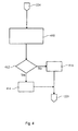
Fig. 4 shows a flow chart of an algorithm for an ice detection unit ice detection method according to embodiments described herein; -
Fig. 5 shows a schematic drawing illustrating an anemometer used for embodiments described herein; and -
Fig. 6 shows a schematic drawing illustrating an anemometer used for embodiments described herein. - Reference will now be made in detail to the various embodiments of the invention, one or more examples of which are illustrated in the figures. Each example is provided by way of explanation of the invention, and is not meant as a limitation of the invention. For example, features illustrated or described as part of one embodiment can be used on or in conjunction with other embodiments to yield yet a further embodiment. It is intended that the present invention includes such modifications and variations.
- Under certain atmospheric conditions, ice will develop on the turbine components, for example, the anemometers and the blades. The commonly used ice sensor does not provide sufficient accuracy. The inability to detect ice with a desired accuracy may lead to ice-throw from the turbine blades and, as a result, the wind turbine may need to be shut down below a certain temperature.
-
Figure 1 illustrates an embodiment wherein the system for ice detection is provided on awind turbine 100. Anacelle 6 is provided on top of thetower 2. Thehub 4 is rotatably held at thenacelle 6. The rotor blades 8 are mounted to thenacelle 6. The system for ice detection includes twoanemometers nacelle 6. Thefirst anemometer 110 is more easily affected by icing. Thesecond anemometer 120 is less affected by icing. The signals received by the twoanemometers - Further, according to one embodiment, a detection unit for an ice
condition parameter value 130 may be provided. Theanemometers detection unit 130 are connected to an evaluation unit. According to another embodiment, thedetection unit 130 is a temperature sensor known in the art. The temperature sensor measures the temperature and determines whether the temperature is below or above a threshold value. The evaluation unit 140 receives signals from the first and second anemometer and the temperature sensor. As described with respect toFigs. 2 to 4 below, the evaluation unit is adapted to provide a functional relationship between measurement values of the first anemometer and the second anemometer. Generally, by comparing the signal of theanemometer 120 and the signal of theanemometer 110, an ice detection signal can be generated. - According to one embodiment, the
anemometer 120 is a heated sonic anemometer that does not ice easily. Theanemometer 110 is a cup anemometer, which is more likely affected by icing. Therefore, on occurrence of icing at the nacelle in particularly thesecond anemometer 110 is affected by icing. The signals of thefirst anemometer 120 and the signals of thesecond anemometer 110 will indicate a difference in wind velocity. The differences will be described in more detail with regard to the methods illustrated inFigs. 2 to 4 and the anemometers illustrated inFigs. 5 and 6 . -
Figure 2 shows a flowchart illustrating a method conducted for an ice detection system. The method starts atstep 210, wherein the system is initialized and, for example, predetermined parameter values are read from a memory, predetermined parameter values are provided by a user interface, or the like. Within step 212 a measured ice condition value is compared to an ice condition threshold parameter. - According to one embodiment, the ice condition threshold parameter is a temperature value. For example, if the temperature is measured with a temperature sensor and the measured temperature is above a predetermined temperature threshold parameter value, an icing condition may not occur. On the other side, if the measured temperature is below a temperature threshold parameter value, there is some likelihood that an icing condition may occur. Therefore, within
step 212, it is verified if conditions are present, in which an icing condition can not occur. Such conditions can, e.g., be determined by a temperature of at least a threshold value in the range of 3°C to 7°C, or even higher temperatures. If the temperature would be for example below 5°C as a threshold value, an icing condition might occur. - If within
step 212 it has been verified that there is no danger of icing (e.g., T > Tth: yes), the method proceeds withstep 214. The left-hand side of the flowchart hereby provides a calibration branch of the method. According to one embodiment, the calibration is conducted during a condition, at which it is impossible that icing may occur. According to another embodiment, for example if icing conditions are present during long periods of operation of the wind turbine, the calibration is conducted for an icing condition threshold parameters for which it is very unlikely that an icing condition may occur. - Generally, within the embodiments described herein, a calibration is conducted for data sets gained under a condition during which no icing is present and the resulting calibration values are used for detection of an icing condition in the event the ice condition threshold parameter value indicates that an icing condition may occur.
- With in
step 214, a histogram of data sets, that is a histogram of signal values from the first anemometer and values from the second anemometer, respectively, are created. According to one embodiment, the histogram of the created data sets may include values in a minimum wind velocity range. According to another embodiment, the histogram of the created data sets may include values in a maximal wind velocity range. According to an even further embodiment, the created histogram may include values in a minimum and maximum wind velocity range. After generation of the histogram of the data sets, withinstep 216, it is evaluated whether the data sets include a sufficient number of values in each of the desired ranges. According to a further embodiment, the histogram may also be evaluated with respect to the minimum number of values per bin of the histogram. - After the distribution (histogram) of the measured data sets has been evaluated in
step 216 and the data sets meet the requirements for a calibration (yes),step 218 leads to a calibration method as illustrated inFig. 3 . Otherwise, the method proceeds to thestep 230. Instep 230 one algorithm cycle ends and another algorithm cycle may start. - A histogram of the data sets may, for example, be insufficient if only small wind velocity variations occurred during generation of the data sets. According to an embodiment, in the event data sets with an insufficient histogram for a calibration are generated these data sets might be combined with further measurement values of the first and the second anemometers, i.e., values of previous data sets or external data sets.
- These further data sets may according to one embodiment be imported from a similar wind turbine. According to another embodiment, a longer data set generation period may be provided to generate more values of the first anemometer and the second anemometer. In the event imported data values are used, it is further possible to bit by bit substitute the important data by measured data after the available number of measured values in the data sets is increased. According to another embodiment, older data values may even be deleted if the number of available values in the histogram allows deletion of older values from the data sets.
- Next, before describing the
ice detection step 222 ofFig. 2 , the calibration illustrated inFig. 3 will be described. The embodiments illustrated with regard toFig. 3 , start instep 218 as a transfer step from the general system method to the calibration method. - Within
step 310, the first anemometer may be defined as the reference anemometer and the second anemometer may be defined as the test anemometer. According to another embodiment, the first anemometer may be the test of anemometer and the second anemometer may be the reference anemometer. - Then, a linear regression is performed between the values of the two data sets corresponding to the two anemometers, respectively. As a result of the linear regression, a slope b, an offset a, and a coefficient of determination r2 is calculated. Next, within
step 312, a residual analysis of the data sets is performed. Therein, the residuals of the individual values of the data sets as compared to the linear regression gained instep 310 are calculated. Further, the standard deviation of the residuals is provided as a first calibration value. Withinstep 314, the first calibration value, that is the standard deviation of the residuals, is multiplied with a fixed parameter. - According to one embodiment, the fixed parameter is a predetermined value used for a plurality of wind turbines. The product of the standard deviation of the residuals and the fix parameter provides a maximum residual defining the limit value for an ice detection. According to another embodiment, the fixed parameter is the least 2. According to an even further embodiment, the fixed parameter is in a range of 3 to 20. Thus, within these embodiments, a limit value, which defines a threshold for ice detection, is determined in
step 314. - Within
step 316, a test may be conducted on at least one element selected from the group consisting of: the slope b, the offset a, the coefficient of determination r2, and the number of residuals being larger than a maximum residual. - If for example the slope b, the offset a, or the coefficient of determination r2 is outside a predetermined range, the method proceeds to step 318 where an ice detection unit failure flag is set to equal one. The same applies if the number of residuals being larger than a maximum residual exceeds a predetermined threshold. Thereby, an operator can be informed that the calibration failed or the ice detection unit is defective. If the slope b, the offset a, the coefficient of determination r2, and the number of residuals being larger than a maximum residual is within a desired predetermined range, the calibration is defined successful in
step 319, the ice detection unit failure flag is set to zero and the method proceeds instep 219 to the ice detection system method illustrated infigure 2 . - According to a further, alternative, embodiment, if two or more elements selected from the group consisting of the slope b, the offset a, the coefficient of determination r2, and the number of residuals being larger than a maximum residual are outside a predetermined range, the method proceeds to step 318 where an ice detection unit failure flag is set to equal one. Thereby, an operator can be informed that the calibration failed or the ice detection unit is defective. Otherwise, the calibration is defined successful in
step 319, the ice detection unit failure flag is set to zero and the method proceeds instep 219 to the ice detection system method illustrated infigure 2 . - If within
step 212 it has been verified that there is some risk of icing (e.g., T > Tth: No), the method proceeds withstep 222. Withinstep 222 infigure 2 , it is determined whether a field calibration has been conducted. A field calibration is to be understood as a calibration of one of the embodiments described with respect tofigure 3 , and which is conducted on the same wind turbine as the ice detection system is used. - According to a one embodiment, in the event no field calibration has been conducted and there is no available field data to conduct a calibration, experience values may be loaded and the calibration may be conducted with external data sets. According to another embodiment data sets are present from the wind turbine itself, and a calibration has been conducted or can be conducted with the data sets. According to an even further embodiment, data sets are present from the wind turbine itself, but the histogram might not be sufficient. Then additional external data might be added to the measured data sets to calibrate the ice detection unit.
- In light of the above, values for a sloped b, an offset a, and the standard deviation of the residuals as a first calibration values or an ice detection limit value as the product of the first calibration value and a predetermined factor can be provided in
step 222. Withinstep 224, the method proceeds to the ice detection procedure described with respect tofigure 4 . Withinfigure 4 , the ice detection method starts with thetransfer step 224 from the ice detection system method offigure 2 . - Within step 410 a residual analysis of the present data point is conducted. Thereby, the linear regression values slope b offset a, are used to convert one anemometer value. The converted value is compared to the other anemometer value and the residual is calculated. A residual of the present data point is determined. That is, it is determined how much one of the anemometers differs from the value calculated by the linear function of the other anemometer based on the calibrated slope and offset.
- Further, the standard deviation of the residuals (as first calibration value) or the limit value as the product of the first calibration value and a predetermined factor is used. Within
step 412, it is determined whether the residual of the present data point exceeds the limit value (product of first calibration value and fixed parameter). If the residual of the present data point exceeds the limit value, an ice counting indicator is increased by one (step 412). If the residual of the present data point is below the limit value, the ice counter indicator is set to zero (step 416). - Further, within
step 225 the method returns to the main ice detection system algorithm. In light of the ice counting indicator, it is according to one embodiment possible that ice detection can be indicated if the ice counter value is larger than zero. Thus, one data point that indicates ice detection may be used as an indicator for icing. However, according to another typical embodiment, the ice detection system may indicate icing of the wind turbine only if the ice detection counter indicates a value larger than 1. Thereby, an icing condition is only indicated if the ice detection has at least been verified by a second ice detection data point. - After the algorithm returned to step 225 of the method described with regard to
Fig. 2 , one cycle terminates instep 230. - According to the embodiments described above, the ice detection of a wind turbine can be improved at least by a factor of 5. For example, a commonly used ice sensor used in a harsh climate may result in about 14 % wrong icing condition indications. This means, for 14% of the ice detection events either icing is indicated in the event no icing condition was present at the nacelle or no icing indication is given for an event when icing was actually present. As a comparison in a similar harsh climate it is possible to lower the amount of erroneous icing indications with ice detection systems described herein to a value below 1.5 %. Additionally, the confidence levels for the ice detection system can be improved from 85% to be near 60%. This means the ice detection system including the anemometer algorithms is almost as good as a reference ice signal.
- Embodiments of anemometers are illustrated in
Figs. 5 and 6. Fig. 5 shows acup anemometer 500. On themain body 510 an axis orshaft 512 is provided.Cups 514 are mounted to thearms 516, which are rotatably fixed to the axis or shaft by aring 518. The ring can rotate around the axis orshaft 512. According to one embodiment, the axis orshaft 512 and/or thering 518 can be heated with a power of, e.g., 15 to 20 W. Thereby, influence of icing on the anemometer is reduced. However, as the cups may still ice over, the anemometer is relatively easy affected by icing. According to another embodiment theanemometer 500 is not heated. Thereby, climate influences are even stronger. Generally, the embodiments of a cup anemometer include three cups. However, according to other embodiments cup anemometers with four cups may also be utilized. -
Fig. 6 shows an embodiment of a sonic anemometer. On themain body 610arms - Further according to one embodiment, if transceivers are used, the sound propagation velocity in both directions from
arm 612 toarm 614 and vice versa may be measured. Thus, dependencies of the velocity of propagation of sound from the air temperature can be eliminated. According to another embodiment, thesonic anemometer 600 can further be provided with heating. Thereby, further temperature influences apart from the air temperature can be eliminated. Consequently, the anemometers according to the embodiments described with regard toFig. 6 are not or almost not affected by icing. - According to one embodiment, the ice detection system for a wind turbine illustrated in
Fig. 1 includes a heated sonic anemometer (600 inFig. 6 ) as thefirst anemometer 120 and a shaft heated cup anemometer (500 inFig. 5 ). - According to the embodiments described herein, an improved ice detection system can be provided and the turbine may be operated with the ice detection system to prevent ice-throw as much as possible.
- This written description uses examples to disclose the invention, including the best mode, and also to enable any person skilled in the art to make and use the invention. While the invention has been described in terms of various specific embodiments, those skilled in the art will recognize that the invention can be practiced with modification within the spirit and scope of the claims. Especially, mutually non-exclusive features of the embodiments described above may be combined with each other. The patentable scope of the invention is defined by the claims, and may include other examples that occur to those skilled in the art. Such other examples are intended to be within the scope of the claims of they have structural elements that do not differ from the literal language of the claims, or if they include equivalent structural elements with insubstantial differences from the literal languages of the claims.
Claims (10)
- A method for ice detection for a wind turbine (10), comprising:providing an ice condition threshold parameter adapted for distinguishing a condition during which icing may occur and a condition during which icing may not occur;measuring a wind velocity with a first anemometer (110; 500; 600), wherein the first anemometer being of a first type;measuring a wind velocity with a second anemometer (120; 500; 600), wherein the second anemometer being of a second type, and wherein the second type is different from the first type;evaluating, for a condition during which icing may occur, a deviation of the wind velocity measured with the first anemometer and the wind velocity measured with the second anemometer; anddetermine whether the deviation exceeds a limit value based on a calibration conducted under a condition during which icing may not occur.
- The method according to claim 1, further comprising:counting the number of times the deviation exceeds the limit value; andindicating an icing condition of the number of times exceeds a count threshold.
- The method according to claim 1 or claim 2, wherein the limit value is a product of a standard deviation and a fixed parameter, wherein the standard deviation is the standard deviation of the residuals of a regression obtained based on data sets of the first anemometer (110) and the second anemometer (120) measured under a condition during which icing may not occur.
- The method according to any one of the preceding claims, further comprising:heating the first anemometer; andheating the second anemometer;
- The method according to any one of the preceding claims, wherein the data sets are generated at least once a year and the calibration is conducted at least once a year.
- The method according to any one of the preceding claims, wherein the calibration comprises:measuring a data set of a first anemometer for a period and under a condition during which icing may not occur, wherein the first anemometer (110) being of a first type;measuring a data set of a second anemometer (120) corresponding to the period, wherein the second anemometer being of a second type, and wherein the second type is different from the first type; anddefining a functional interrelation between the first data set and the second data set;defining a limit value determining a deviation threshold to indicate an icing condition flag.
- The method according to claim 6, wherein the functional relationship is a linear regression.
- An ice detection unit for a wind turbine (100), comprising:a first anemometer (110; 500; 600) of a first type;a second anemometer (120; 500; 600) of a second type, wherein the second type is different from the first type, and wherein the second anemometer is heatable to reduce affection of the second anemometer by ice;a temperature sensor (130) adapted for measuring an ice condition threshold parameter to distinguish a condition during which icing may occur and a condition during which icing may not occur; andan evaluation unit (140) adapted for evaluating a functional relationship between a signal from the first anemometer and the second anemometer.
- The ice detection unit according to claim 8 wherein the first anemometer is heatable to reduce affection of the first anemometer by ice, and wherein the second anemometer is a heated ultrasonic anemometer.
- A wind turbine (100) comprising:an ice detection unit according to claim 8 or claim 9.
Applications Claiming Priority (1)
| Application Number | Priority Date | Filing Date | Title |
|---|---|---|---|
| US11/610,042 US7487673B2 (en) | 2006-12-13 | 2006-12-13 | Ice detection based on anemometry |
Publications (3)
| Publication Number | Publication Date |
|---|---|
| EP1936184A2 true EP1936184A2 (en) | 2008-06-25 |
| EP1936184A3 EP1936184A3 (en) | 2014-12-31 |
| EP1936184B1 EP1936184B1 (en) | 2020-03-04 |
Family
ID=39263105
Family Applications (1)
| Application Number | Title | Priority Date | Filing Date |
|---|---|---|---|
| EP07122650.0A Active EP1936184B1 (en) | 2006-12-13 | 2007-12-07 | Ice detection based on anemometry |
Country Status (4)
| Country | Link |
|---|---|
| US (1) | US7487673B2 (en) |
| EP (1) | EP1936184B1 (en) |
| CN (1) | CN101201413B (en) |
| DK (1) | DK1936184T3 (en) |
Cited By (5)
| Publication number | Priority date | Publication date | Assignee | Title |
|---|---|---|---|---|
| EP2317131A3 (en) * | 2009-10-28 | 2011-07-27 | General Electric Company | System and method for wind friction monitoring |
| EP2592447A1 (en) | 2011-11-08 | 2013-05-15 | Topwind Consultancy B.V. | Frost condition detection system and method |
| EP3486481A1 (en) * | 2017-11-16 | 2019-05-22 | Senvion GmbH | Method and system for detecting an icing condition of a wind turbine |
| WO2019120408A1 (en) * | 2017-12-22 | 2019-06-27 | Vestas Wind Systems A/S | Determining icing condition using mechanical wind sensor |
| WO2023011696A1 (en) * | 2021-08-06 | 2023-02-09 | Vestas Wind Systems A/S | Method of calibrating a reference of a wind turbine |
Families Citing this family (34)
| Publication number | Priority date | Publication date | Assignee | Title |
|---|---|---|---|---|
| US7708524B2 (en) * | 2006-12-21 | 2010-05-04 | General Electric Company | Method and system for utilizing lateral tower acceleration to detect asymmetric icing |
| US7895018B2 (en) * | 2007-08-10 | 2011-02-22 | General Electric Company | Event monitoring via combination of signals |
| DE102008007519A1 (en) * | 2008-02-05 | 2009-08-13 | Nordex Energy Gmbh | Device for monitoring the speed in a wind turbine |
| EP2123906A1 (en) * | 2008-05-21 | 2009-11-25 | Siemens Aktiengesellschaft | Method and apparatus for damping tower oscillation in a wind turbine |
| US8050887B2 (en) * | 2008-12-22 | 2011-11-01 | General Electric Company | Method and system for determining a potential for icing on a wind turbine blade |
| US8039980B2 (en) * | 2009-06-26 | 2011-10-18 | Mitsubishi Heavy Industries, Ltd. | Wind turbine generator and method of controlling the same |
| US8747563B2 (en) | 2009-10-09 | 2014-06-10 | University Of Kansas | Method and apparatus for anti-fouling an anemometer |
| US10137542B2 (en) | 2010-01-14 | 2018-11-27 | Senvion Gmbh | Wind turbine rotor blade components and machine for making same |
| MX341495B (en) | 2010-01-14 | 2016-08-23 | Neptco Inc * | WIND TURBINE ROTOR BLADE COMPONENTS AND METHODS FOR THE MANUFACTURE OF THE SAME. |
| US8430634B2 (en) * | 2010-02-03 | 2013-04-30 | Herbert Williams | System and method for improving wind turbine efficiency by adjusting blade pitch in response to localized wind speed |
| CN101776695B (en) * | 2010-03-08 | 2011-12-14 | 江苏省电力试验研究院有限公司 | Wind speed and wind direction measuring method for wind power generation system |
| CN102834610B (en) | 2010-04-12 | 2016-06-15 | 西门子公司 | Determine the method and system that the quality on the rotating vane of wind turbine changes |
| DE202010009461U1 (en) * | 2010-06-23 | 2010-09-16 | Nordex Energy Gmbh | Device for heating weather masts |
| GB2481789A (en) * | 2010-06-30 | 2012-01-11 | Vestas Wind Sys As | Reducing yaw error in wind turbines |
| EP2434146A1 (en) | 2010-09-24 | 2012-03-28 | Siemens Aktiengesellschaft | Method of and device for determining a mass condition of a rotor of a wind turbine, and method of operating a wind turbine |
| US20120226485A1 (en) | 2011-03-03 | 2012-09-06 | Inventus Holdings, Llc | Methods for predicting the formation of wind turbine blade ice |
| DE102011077129A1 (en) * | 2011-06-07 | 2012-12-13 | Aloys Wobben | Method for operating a wind energy plant |
| EP2795120A2 (en) * | 2011-12-22 | 2014-10-29 | Vestas Wind Systems A/S | A wind turbine blade ice accretion detector |
| US9846261B2 (en) | 2012-05-31 | 2017-12-19 | UNIVERSITé LAVAL | Method and apparatus for determining an icing condition status of an environment |
| EP2778404A1 (en) * | 2013-03-14 | 2014-09-17 | Siemens Aktiengesellschaft | Method to de-ice wind turbines of a wind park |
| CN105121845B (en) * | 2013-04-12 | 2018-12-28 | 维斯塔斯风力系统集团公司 | It is related to the improvement of wind turbine sensor |
| US9528493B2 (en) * | 2013-05-28 | 2016-12-27 | Siemens Aktiengesellschaft | Apparatus to detect aerodynamic conditions of blades of wind turbines |
| DE102013108626A1 (en) * | 2013-08-09 | 2015-02-12 | Kriwan Industrie-Elektronik Gmbh | wind sensor |
| CA3012392C (en) | 2015-03-12 | 2021-04-27 | Universite Laval | System and method for determining an icing condition status of an environment |
| DE102015117032A1 (en) * | 2015-10-07 | 2017-04-13 | Wobben Properties Gmbh | Method for monitoring a wind turbine |
| WO2017108064A1 (en) | 2015-12-23 | 2017-06-29 | Vestas Wind Systems A/S | Improved electro-thermal heating |
| CN105402093B (en) * | 2015-12-30 | 2018-06-08 | 国电联合动力技术有限公司 | A kind of wind turbine freezing detection method and device for wind field rank |
| CN106290970A (en) * | 2016-07-28 | 2017-01-04 | 无锡信大气象传感网科技有限公司 | A kind of anemoclinograph for frost region |
| CN108005863B (en) * | 2016-11-02 | 2019-09-13 | 北京金风科创风电设备有限公司 | wind-driven rotating device and driving method thereof |
| WO2018113877A1 (en) * | 2016-12-22 | 2018-06-28 | Vestas Wind Systems A/S | Improved wind turbine safety system |
| DK3559457T3 (en) | 2016-12-22 | 2020-09-21 | Vestas Wind Sys As | TEMPERATURE CONTROL BASED ON WEATHER FORECAST |
| CN112556728B (en) * | 2019-09-25 | 2022-07-19 | 中国航发商用航空发动机有限责任公司 | Anti-icing sensor and have its engine |
| CN113915080A (en) * | 2021-11-15 | 2022-01-11 | 四川建筑职业技术学院 | Blade icing operation detection and control method for wind generating set |
| CN116052371B (en) * | 2023-01-03 | 2025-06-03 | 广州市市政工程试验检测有限公司 | Inhaul cable ice falling risk monitoring and early warning method and system |
Family Cites Families (12)
| Publication number | Priority date | Publication date | Assignee | Title |
|---|---|---|---|---|
| US4930343A (en) * | 1989-03-27 | 1990-06-05 | Haden, Inc. | Apparatus for measuring and controlling fluid flow across a boundary |
| US5639963A (en) * | 1996-03-07 | 1997-06-17 | Sustare, Jr.; George Allan | Multi-directional wind direction and speed indicating apparatus |
| ES2228121T3 (en) * | 1999-11-03 | 2005-04-01 | Vestas Wind Systems A/S | PROCEDURE FOR CONTROLLING THE OPERATION OF AN ELECTRIC TURBINE AND ELECTRIC TURBINE FOR USE IN THIS PROCEDURE. |
| DE10157759C1 (en) * | 2001-11-27 | 2003-01-23 | Aloys Wobben | Monitoring flow rate sensor involves comparing flow rate indicated by sensor with at least one operating parameter of system operated by medium such as wind power system |
| DE10323785B4 (en) * | 2003-05-23 | 2009-09-10 | Wobben, Aloys, Dipl.-Ing. | Method for detecting an ice accumulation on rotor blades |
| JP4304023B2 (en) * | 2003-08-07 | 2009-07-29 | 富士重工業株式会社 | Horizontal axis wind turbine and control method of horizontal axis wind turbine |
| JP4434661B2 (en) * | 2003-08-11 | 2010-03-17 | 富士重工業株式会社 | Horizontal axis wind turbine and wind-up angle measurement method |
| US6890152B1 (en) * | 2003-10-03 | 2005-05-10 | General Electric Company | Deicing device for wind turbine blades |
| JP4589633B2 (en) * | 2004-01-29 | 2010-12-01 | 富士重工業株式会社 | Horizontal axis wind turbine and control method of horizontal axis wind turbine |
| ES2386895T3 (en) | 2005-07-28 | 2012-09-05 | General Electric Company | Freeze detection system for a wind turbine |
| US7348683B2 (en) * | 2005-11-17 | 2008-03-25 | General Electric Company | Rotor for a wind energy turbine |
| US7883317B2 (en) * | 2007-02-02 | 2011-02-08 | General Electric Company | Method for optimizing the operation of a wind turbine |
-
2006
- 2006-12-13 US US11/610,042 patent/US7487673B2/en active Active
-
2007
- 2007-12-07 EP EP07122650.0A patent/EP1936184B1/en active Active
- 2007-12-07 DK DK07122650.0T patent/DK1936184T3/en active
- 2007-12-13 CN CN2007101995500A patent/CN101201413B/en active Active
Cited By (7)
| Publication number | Priority date | Publication date | Assignee | Title |
|---|---|---|---|---|
| EP2317131A3 (en) * | 2009-10-28 | 2011-07-27 | General Electric Company | System and method for wind friction monitoring |
| EP2592447A1 (en) | 2011-11-08 | 2013-05-15 | Topwind Consultancy B.V. | Frost condition detection system and method |
| EP3486481A1 (en) * | 2017-11-16 | 2019-05-22 | Senvion GmbH | Method and system for detecting an icing condition of a wind turbine |
| WO2019120408A1 (en) * | 2017-12-22 | 2019-06-27 | Vestas Wind Systems A/S | Determining icing condition using mechanical wind sensor |
| US11384738B2 (en) | 2017-12-22 | 2022-07-12 | Vestas Wind Systems A/S | Determining icing condition using mechanical wind sensor |
| WO2023011696A1 (en) * | 2021-08-06 | 2023-02-09 | Vestas Wind Systems A/S | Method of calibrating a reference of a wind turbine |
| US12297806B2 (en) | 2021-08-06 | 2025-05-13 | Vestas Wind Systems A/S | Method of calibrating a reference of a wind turbine |
Also Published As
| Publication number | Publication date |
|---|---|
| EP1936184B1 (en) | 2020-03-04 |
| CN101201413B (en) | 2013-03-13 |
| US7487673B2 (en) | 2009-02-10 |
| DK1936184T3 (en) | 2020-06-08 |
| US20080141768A1 (en) | 2008-06-19 |
| CN101201413A (en) | 2008-06-18 |
| EP1936184A3 (en) | 2014-12-31 |
Similar Documents
| Publication | Publication Date | Title |
|---|---|---|
| EP1936184B1 (en) | Ice detection based on anemometry | |
| US7823437B2 (en) | Anemometer calibration method and wind turbine | |
| CN101971109B (en) | A method and a control system for controlling a wind turbine | |
| US8183707B2 (en) | Method of controlling a wind energy system and wind speed sensor free wind energy system | |
| US20070193333A1 (en) | System and method for determining functionality or accuracy of a sensor | |
| US7603202B2 (en) | Method for optimizing the operation of wind farms | |
| US8408871B2 (en) | Method and apparatus for measuring air flow condition at a wind turbine blade | |
| EP3314120B1 (en) | Blade load sensing system for a wind turbine | |
| CN101970866B (en) | A control system and a method for redundant control of a wind turbine | |
| US8847419B2 (en) | Control device for a wind turbine | |
| EP2388476A2 (en) | Method for temperature calibration of blade strain gauges and wind turbine rotor blade containing strain gauges | |
| EP3870852B1 (en) | Controller for a wind farm | |
| TW201741561A (en) | Estimation of yaw misalignment for a wind turbine | |
| WO2011101475A2 (en) | A method of operating a wind turbine to provide a corrected power curve | |
| US20170292501A1 (en) | System and Method for Auto-Calibrating a Load Sensor System of a Wind Turbine | |
| Smith et al. | Applicability of nacelle anemometer measurements for use in turbine power performance tests | |
| WO2019007579A1 (en) | Determining a wind speed value | |
| US20230383731A1 (en) | Damage assessment arrangement | |
| US20230272783A1 (en) | Device for identifying an accumulation of ice on rotor blades of a wind turbine and method for teaching such a device | |
| CN102967400B (en) | Wind turbines power characteristic method of testing under a kind of complicated landform | |
| EP3816436A1 (en) | Wind speed estimation arrangement | |
| CN216665824U (en) | Blade surface stress monitoring system | |
| CN112145358B (en) | Wind generating set and calibration method of wind direction rose diagram thereof | |
| EP3816437A1 (en) | Wind turbine rotor blade strain estimation arrangement | |
| Arranz | Recommendation for re-working IEC 61400-12-2 methods for the use of spinner anemometry. PTP Deliverable D8. 3 |
Legal Events
| Date | Code | Title | Description |
|---|---|---|---|
| PUAI | Public reference made under article 153(3) epc to a published international application that has entered the european phase |
Free format text: ORIGINAL CODE: 0009012 |
|
| AK | Designated contracting states |
Kind code of ref document: A2 Designated state(s): AT BE BG CH CY CZ DE DK EE ES FI FR GB GR HU IE IS IT LI LT LU LV MC MT NL PL PT RO SE SI SK TR |
|
| AX | Request for extension of the european patent |
Extension state: AL BA HR MK RS |
|
| PUAL | Search report despatched |
Free format text: ORIGINAL CODE: 0009013 |
|
| AK | Designated contracting states |
Kind code of ref document: A3 Designated state(s): AT BE BG CH CY CZ DE DK EE ES FI FR GB GR HU IE IS IT LI LT LU LV MC MT NL PL PT RO SE SI SK TR |
|
| AX | Request for extension of the european patent |
Extension state: AL BA HR MK RS |
|
| RIC1 | Information provided on ipc code assigned before grant |
Ipc: F03D 11/00 20060101AFI20141121BHEP |
|
| 17P | Request for examination filed |
Effective date: 20150630 |
|
| RBV | Designated contracting states (corrected) |
Designated state(s): AT BE BG CH CY CZ DE DK EE ES FI FR GB GR HU IE IS IT LI LT LU LV MC MT NL PL PT RO SE SI SK TR |
|
| AKX | Designation fees paid |
Designated state(s): DE DK ES |
|
| AXX | Extension fees paid |
Extension state: MK Extension state: BA Extension state: RS Extension state: AL Extension state: HR |
|
| 17Q | First examination report despatched |
Effective date: 20160817 |
|
| REG | Reference to a national code |
Ref country code: DE Ref legal event code: R079 Ref document number: 602007059928 Country of ref document: DE Free format text: PREVIOUS MAIN CLASS: F03D0001000000 Ipc: F03D0080400000 |
|
| GRAP | Despatch of communication of intention to grant a patent |
Free format text: ORIGINAL CODE: EPIDOSNIGR1 |
|
| RIC1 | Information provided on ipc code assigned before grant |
Ipc: F03D 80/40 20160101AFI20190304BHEP |
|
| INTG | Intention to grant announced |
Effective date: 20190408 |
|
| GRAJ | Information related to disapproval of communication of intention to grant by the applicant or resumption of examination proceedings by the epo deleted |
Free format text: ORIGINAL CODE: EPIDOSDIGR1 |
|
| INTC | Intention to grant announced (deleted) | ||
| GRAP | Despatch of communication of intention to grant a patent |
Free format text: ORIGINAL CODE: EPIDOSNIGR1 |
|
| INTG | Intention to grant announced |
Effective date: 20190920 |
|
| GRAS | Grant fee paid |
Free format text: ORIGINAL CODE: EPIDOSNIGR3 |
|
| GRAA | (expected) grant |
Free format text: ORIGINAL CODE: 0009210 |
|
| AK | Designated contracting states |
Kind code of ref document: B1 Designated state(s): DE DK ES |
|
| REG | Reference to a national code |
Ref country code: DE Ref legal event code: R096 Ref document number: 602007059928 Country of ref document: DE |
|
| REG | Reference to a national code |
Ref country code: DK Ref legal event code: T3 Effective date: 20200602 |
|
| PG25 | Lapsed in a contracting state [announced via postgrant information from national office to epo] |
Ref country code: ES Free format text: LAPSE BECAUSE OF FAILURE TO SUBMIT A TRANSLATION OF THE DESCRIPTION OR TO PAY THE FEE WITHIN THE PRESCRIBED TIME-LIMIT Effective date: 20200304 |
|
| REG | Reference to a national code |
Ref country code: DE Ref legal event code: R097 Ref document number: 602007059928 Country of ref document: DE |
|
| PLBE | No opposition filed within time limit |
Free format text: ORIGINAL CODE: 0009261 |
|
| STAA | Information on the status of an ep patent application or granted ep patent |
Free format text: STATUS: NO OPPOSITION FILED WITHIN TIME LIMIT |
|
| 26N | No opposition filed |
Effective date: 20201207 |
|
| P01 | Opt-out of the competence of the unified patent court (upc) registered |
Effective date: 20230530 |
|
| REG | Reference to a national code |
Ref country code: DE Ref legal event code: R082 Ref document number: 602007059928 Country of ref document: DE Representative=s name: ZIMMERMANN & PARTNER PATENTANWAELTE MBB, DE Ref country code: DE Ref legal event code: R082 Ref document number: 602007059928 Country of ref document: DE Ref country code: DE Ref legal event code: R081 Ref document number: 602007059928 Country of ref document: DE Owner name: GENERAL ELECTRIC RENOVABLES ESPANA, S.L., ES Free format text: FORMER OWNER: GENERAL ELECTRIC COMPANY, SCHENECTADY, N.Y., US |
|
| REG | Reference to a national code |
Ref country code: DE Ref legal event code: R082 Ref document number: 602007059928 Country of ref document: DE Representative=s name: ZIMMERMANN & PARTNER PATENTANWAELTE MBB, DE |
|
| PGFP | Annual fee paid to national office [announced via postgrant information from national office to epo] |
Ref country code: DE Payment date: 20251126 Year of fee payment: 19 |
|
| PGFP | Annual fee paid to national office [announced via postgrant information from national office to epo] |
Ref country code: DK Payment date: 20251119 Year of fee payment: 19 |