EP1936135A1 - Hydraulic control device for engine - Google Patents
Hydraulic control device for engine Download PDFInfo
- Publication number
- EP1936135A1 EP1936135A1 EP06821970A EP06821970A EP1936135A1 EP 1936135 A1 EP1936135 A1 EP 1936135A1 EP 06821970 A EP06821970 A EP 06821970A EP 06821970 A EP06821970 A EP 06821970A EP 1936135 A1 EP1936135 A1 EP 1936135A1
- Authority
- EP
- European Patent Office
- Prior art keywords
- oil
- engine
- hydraulic pressure
- switching valve
- valve
- Prior art date
- Legal status (The legal status is an assumption and is not a legal conclusion. Google has not performed a legal analysis and makes no representation as to the accuracy of the status listed.)
- Granted
Links
Images



Classifications
-
- F—MECHANICAL ENGINEERING; LIGHTING; HEATING; WEAPONS; BLASTING
- F01—MACHINES OR ENGINES IN GENERAL; ENGINE PLANTS IN GENERAL; STEAM ENGINES
- F01M—LUBRICATING OF MACHINES OR ENGINES IN GENERAL; LUBRICATING INTERNAL COMBUSTION ENGINES; CRANKCASE VENTILATING
- F01M1/00—Pressure lubrication
- F01M1/16—Controlling lubricant pressure or quantity
-
- F—MECHANICAL ENGINEERING; LIGHTING; HEATING; WEAPONS; BLASTING
- F01—MACHINES OR ENGINES IN GENERAL; ENGINE PLANTS IN GENERAL; STEAM ENGINES
- F01M—LUBRICATING OF MACHINES OR ENGINES IN GENERAL; LUBRICATING INTERNAL COMBUSTION ENGINES; CRANKCASE VENTILATING
- F01M1/00—Pressure lubrication
- F01M1/08—Lubricating systems characterised by the provision therein of lubricant jetting means
Definitions
- the present invention relates to engine hydraulic control apparatuses that can appropriately control the hydraulic pressure of an engine.
- oil for lubrication which is stored in an oil pan, is drawn and feed by an oil pump, and an oil passage for supplying lubricant to each of the lubricated parts is formed.
- an oil relief passage is connected to the oil passage downstream of the oil pump, and the oil relief passage is provided with an oil relief valve that opens when the pressure (hydraulic pressure) inside the oil passage that accompanies the feeding of the oil by the oil pump becomes equal to or greater than a set pressure. The excess oil returns to the oil pan, and the maximum hydraulic pressure in the oil passage is thereby regulated.
- an oil pump has been proposed in which, during a low temperature startup, when the viscosity of the oil becomes high, the load that is applied to the oil pump is reduced by increasing the oil relief from the oil passage, and thereby an improvement in the startup characteristics is realized (Patent Document 1).
- Patent Document 1 when the engine is started up, a flywheel is rotated by a starter motor, and the flywheel must reach a minimum rotating speed that enables the engine to be started-up.
- the load that is applied to the oil pump increases because the flow resistance of the oil that is flowing through the oil passage increases, and this acts as a reactive force against the starter motor drive power.
- a first oil relief passage that communicates the oil passage that is downstream of the oil pump and the oil pan, and a second oil relief passage that is parallel thereto are provided.
- An oil relief valve that opens when the hydraulic pressure inside the oil passage becomes equal to or greater than a set value is provided on the first oil relief passage, and an oil relief passage opening and closing valve that opens due to temperature and a startup signal is provided on the second oil relief passage.
- the oil relief passage opening and closing valve opens during low temperatures when the viscosity of the oil becomes high, and a portion of the oil is returned to the oil pan via the second oil relief passage.
- the load that is applied to the oil pump is reduced because the hydraulic pressure downstream of the oil pump becomes low.
- Patent Document 2 discloses an oil passage structure for an engine in which, even if there is a change in the oil viscosity that accompanies a change in temperature, the load on the oil pump is reduced while ensuring the minimum hydraulic pressure that is necessary for a normal startup, and the startup characteristics are improved.
- an oil passage structure for an engine that is provided with a first oil relief passage that communicates the oil passage downstream of the oil pump and the oil pan and a second oil relief passage that is parallel thereto, and an oil relief valve that opens when the hydraulic pressure in the oil passage becomes equal to or greater than a set hydraulic pressure is provided on the first oil relief passage and an oil relief passage opening and closing valve that opens due to a startup signal is provided on the second oil relief passage, wherein the second oil relief valve serial to the oil relief passage opening and closing valve is provided on the second oil relief passage, and the valve opening pressure of this second oil relief valve is set so as to be lower than the valve opening pressure of the oil relief valve that is provided on the first oil relief passage and this second oil relief valve opens due to a hydraulic pressure that is equal to or greater than a minimum hydraulic pressure that is necessary during a startup.
- the oil relief passage opening and closing valve that is provided on the second oil relief passage is opened, and during a low temperature startup, the load that is applied to the oil pump can be reduced by lowering the hydraulic pressure downstream of the oil pump.
- the opening of the second relief valve is carried out by a hydraulic pressure that is equal to or greater than a minimum hydraulic pressure that is necessary during startup, even when there is a change in the viscosity of the oil, the oil does not return to the oil pan excessively, and the amount of oil that is necessary during a startup is ensured.
- piston jets are one among the various mechanisms that are incorporated into an engine that appropriately cool the parts of the engine after a warm-up has been completed. These inject oil toward the piston that is in operation to realize cooling of the area around the piston. These piston jets operate such that when the hydraulic pressure inside the oil passage becomes equal to or greater than a predetermined value, nozzles that face the pistons open and oil is injected.
- the engine hydraulic control apparatus of the present invention is an apparatus that controls the hydraulic pressure of the engine, and includes an oil pump that draws oil from an oil tank; a piston jet that opens when the hydraulic pressure of the oil that has been drawn by the oil pump reaches a valve opening pressure Qa and injects oil towards a piston through an oil injection path; a relief valve that is disposed on an oil return path, which is different from the oil injection path, and that opens when the hydraulic pressure of the oil that has been drawn by the oil pump reaches a valve opening pressure Qb; and a switching valve that is disposed on the oil return path; characterized in that the valve opening pressure Qb is set to a valve opening pressure that is within a range of the hydraulic pressure that is necessary to ensure the necessary amount of oil required to lubricate the engine and is lower than the valve opening pressure Qa.
- the oil tank may be an oil pan that is installed below the cylinder block, or may be a separate tank.
- the switching valve can be a thermostat that opens during low temperature and enables the oil in the oil return path to flow. If a thermostat is used, the switching valve is opened during low temperatures, when the viscosity of the oil becomes high, and it can raise the hydraulic pressure by closing when the hydraulic pressure has risen as the warm-up progresses. If the hydraulic pressure rises and a valve opening pressure Qa is attained, oil is injected from the piston jets, and the pistons can be cooled.
- the switching valve can be structured such that the opening and closing operation is carried out depending on the engine speed and the engine load.
- the switching valve can be structured so as to use a solenoid or the like that is controlled by an ECU (electronic control unit), and carry out the opening and closing operation based on opening and closing commands that depend on the engine speed and the engine load.
- ECU electronic control unit
- Such a switching valve can refer to various types of values for the engine speed, the engine load and the like in order to carry out opening and closing operation at an appropriate timing. These values can be referred to singly or in appropriate combinations to determine the opening and closing timing. These values are conventionally acquired from various types of sensors that are provided in the engine or the vehicle. For example, it is possible to determine the engine load by the fuel injection rate or the accelerator opening angle.
- such a switching valve is structured such that the switching valve is closed when it has been determined that the engine is in an operating state that requires an amount of oil by referring to the engine speed and the engine load. For example, even when the engine speed is low, the switching valve is closed when the engine load is high so that oil is supplied to each of the lubricated parts. In addition, even in the case in which the speed is low and the load is low, the switching valve is closed when the oil temperature is high, and it is possible to inject oil from the oil jets.
- the switching valve such that the opening and closing operation is carried out by referring to an estimated oil amount, which is estimated by a circulating oil amount estimating means, and it is possible to structure this circulating oil amount estimating means, for example, by an ECU or the like such that the estimated oil amount is calculated based on a hydraulic pressure value that has been acquired by a hydraulic pressure measuring means such as an oil pressure gauge, an oil temperature value that has been acquired by an oil temperature measuring means such as an oil temperature gauge, and the pumping speed.
- a hydraulic pressure measuring means such as an oil pressure gauge
- an oil temperature measuring means such as an oil temperature gauge
- the switching valve such that the valve opening operation is stopped when the hydraulic pressure value has not attained a hydraulic pressure value that has been estimated based on the oil temperature value and the pumping speed.
- the switching valve is closed so that the necessary amount of the oil supply to each of the lubricated parts is not delayed, and the oil that has been drawn by the oil pump cannot return through the oil return path.
- a warning such as lighting a lamp may be carried out so as to inform the driver about the abnormality.
- the valve opening pressure Qb of the relief valve is set to a valve opening pressure that is within a range of necessary hydraulic pressure that can ensure the necessary amount of oil that is required to lubricate the engine and is lower than the valve opening pressure Qa of the piston jets, the relief valve opens before oil is injected by the piston jets when the hydraulic pressure rises accompanying the viscosity of the oil becoming high during a cold startup of the engine, and it is possible to realize a reduction in the friction and a reduction in the load of the oil pump by reducing the hydraulic pressure and to avoid carrying out the injection of oil even though the temperature is low.
- FIG. 1 is a schematic drawing that shows the schematic structure of an engine 2 that incorporates the hydraulic control apparatus 1 of the present invention.
- the hydraulic control apparatus 1 includes an oil pump 4 that draws oil from an oil pan 3 due to the rotation of the crankshaft; a piston jet 6 that opens when the hydraulic pressure of the oil that has been drawn by this oil pump 4 attains a valve opening pressure Qa and injects oil towards a piston (not illustrated) through an oil injection path 5; a relief valve 8 that is disposed on an oil return path 7 that is different from the oil injection path 5, and is opened when the hydraulic pressure of the oil that has been drawn by the oil pump 4 attains a valve opening pressure Qb; and a switching valve 9 that is disposed on the oil return path 7.
- the oil pan 3 corresponds to the oil tank in the present invention.
- a strainer 10 is disposed on the upstream end portion of the oil pump 4.
- the downstream end of the oil return path 7 connects the oil pump 4 and the strainer 10, and the return oil thereby circulates.
- the returning oil returns along the path of the oil without being poured directly into the oil pan 3, and thus the oil in the oil pan 3 does not foam.
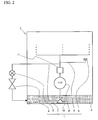
- the oil in the oil pan 3 does not foam, as shown in FIG. 2 , it is possible to use a structure in which the downstream end of the oil return path 7 is connected to a position that is lower than the oil surface of the oil pan 3.
- an oil filter 11 is installed downstream of the oil pump 4.
- the oil injection path 5 and the oil return path 7 divide downstream of this oil filter 11. Due to having such a structure, the flow of contaminants into the switching valve 9 is prevented, and malfunctions due to jamming that is caused by contaminants is prevented. Note that it is also possible to use a structure that can realize a reduction in the friction of the oil pump 4 and an improvement in fuel economy by dividing the oil injection path 5 and the oil return path 7 upstream of the oil filter 11, and releasing the oil to the oil return path 7 before pressure loss increases.
- a relief valve 8 in a hydraulic control apparatus 1 that has such a structure opens when the hydraulic pressure in the path attains a predetermined valve opening pressure Qb.
- This valve opening pressure Qb is set to a valve opening pressure that is within a range of the necessary hydraulic pressure that can ensure the necessary amount of oil that is required for lubricating the engine 2 and is lower than the valve opening pressure Qa of the piston jet 6.
- the switching valve 9 is a thermostat, detects the oil temperature by a thermosensitive portion, and opens during low temperature so that oil that has been drawn by the oil pump 4 flows to the oil return path 7 side.
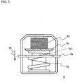
- the specific structure of this switching valve 9 is shown in FIG. 3 .
- the switching valve 9 is one in which a valve body 9b is opened and closed by being pressed toward or separated from a hole 9a1 that is provided in the plate body 9a.
- the switching valve 9 is structured by being provided on one side of the valve body 9b with a spring 9c that urges the valve body 9b in a direction that opens the hole 9a1, and being provided on the other side of the valve body 9b with a piston 9d that contains thermowax.
- the switching valve 9 having such a structure, when this thermowax expands accompanying a rise in temperature in the vicinity thereof, the piston 9c presses the valve body 9b down in the direction of an arrow 30 to close the hole 9a1. Specifically, in the switching valve 7, until reaching the temperature at which the thermowax expands, the valve body 9b, which is urged by the spring 9c, opens the hole 9a1, and when the temperature rises and the piston 9c is pressed down due to the thermowax expanding, the valve body 9b closes the hole 9a1.
- valve opening pressure Qb which is the valve opening pressure of the relief valve 8
- the relief valve 8 opens.
- the oil pressure in the path is reduced, the friction of the oil pump 4 is also reduced, and the load is reduced.
- the relief valve 8 is opened, and thus hydraulic pressure does not rise any further, and the valve opening pressure Qa of the piston jet 6 is not reached.
- a second embodiment of the present invention will be explained with reference to FIG. 4 .
- the point on which a hydraulic control apparatus 20 that is shown in FIG. 4 differs from the hydraulic control apparatus 1 of the first embodiment is that, in the hydraulic control apparatus 1 in the first embodiment, the switching valve 9 is a thermostat that carries out opening and closing by detecting the oil temperature, while in contrast, in the hydraulic control apparatus 20 of the second embodiment, a switching valve 21 uses an electromagnetic solenoid that is controlled by an ECU 22, which executes opening and closing commands based on data that has been obtained from a sensor group 23.
- Other structures do not differ from those of the hydraulic control apparatus 1 of the first embodiment, and thus identical reference numerals are attached to identical elements in the figures, and the explanations thereof are omitted.
- the switching valve 21 of such a hydraulic control apparatus 20 carries out the opening and closing operation depending on the engine load based on the engine speed NE, the fuel injection rate Qv, and the accelerator opening angle ACCP.
- a plurality of maps are prepared that are selected depending on the operating conditions, the appropriate map is selected by analyzing the acquired data, and the opening and closing control of the switching valve 21 is carried out.
- the basic method for the control of the switching valve 21 is one in which the switching valve 21 is closed when it has been determined that the engine is in an operating state that requires an amount of oil by referring to the engine speed and the engine load, and the oil is supplied to each of the lubricated parts. Below, an example of the switching valve opening and closing control during a cold startup and after the warm-up has completed will be shown.
- FIG. 5 is a flowchart that shows the switching valve opening and closing control during a cold startup.
- the ECU 22 determines whether the engine 2 is in a pre-warm-up state by acquiring the oil temperature OT ant the water temperature WT from the oil temperature gauge and the water temperature gauge that are included in the sensor group 23 (step S11).
- step S 11 is YES, that is, when it has been determined that the engine 2 is in a pre-warm-up state
- the processing proceeds to step S12.
- step S12 the ECU 22 determines whether or not the engine speed NE has attained a value X1 that is recorded in a map.
- step S12 When it has been determined that step S12 is YES, that is, when it has been determined that the engine speed NE has not attained the value X1, the processing proceeds to step S 13.
- step S 13 it is determined whether or not the engine load, which is found from the fuel injection rate Qv and the accelerator opening angle ACCP, has attained a value Y1 that is recorded in a map.
- step S 14 the ECU 22 opens the switching valve 21. Thereby, the rise of the hydraulic pressure in the path is suppressed, and it is possible to realize a reduction in the friction and the load on the oil pump 4, and to realize an improvement in the fuel economy.
- step S 15 when it has been determined that step S11, step S12, and step S 13 are NO, in all cases the switching valve 21 is closed (step S 15).
- the switching valve 21 In the case in which the measures in step S 15 are taken, because all cases are an operating state in which it is determined that an amount of oil is necessary in each of the lubricated parts, the switching valve 21 is closed and oil is supplied to each of the lubricated parts. Note that the switching valve 21 is closed when no control is being carried out, that is, when the electromagnetic solenoid is not being charged. This is a measure for supplying oil to each of the lubricated parts even in the case in which some sort of abnormality has occurred in the control system or the like and the switching valve 21 does not operate.
- step S21 the ECU 22 determines whether or not the engine speed NE has attained the value X2, which is recorded in the map.
- step S21 it is determined whether or not the engine load, which is found based on the fuel injection rate Qv and the accelerator opening angle ACCP, has attained that value Y2, which is recorded in a map.
- step S22 is YES, that is, when the engine load has not attained the value Y2
- the processing proceeds to step S23.
- step S23 the ECU 22 opens the switching valve 21. Thereby, a rise in the hydraulic pressure in the path is suppressed, and it is possible to realize a reduction in the friction and the load on the oil pump 4, and to realize an improvement in fuel economy.
- step S24 when it has been determined that step S21 and step S22 are NO, in all cases, the switching valve 21 is closed (step S24). In the case in which the measures in step S24 are taken, because all cases are operating states in which it is determined that an amount of oil is necessary for each of the lubricated parts, the switching valve 21 is closed and oil is supplied to each of the lubricated parts.
Landscapes
- Engineering & Computer Science (AREA)
- Mechanical Engineering (AREA)
- General Engineering & Computer Science (AREA)
- Lubrication Of Internal Combustion Engines (AREA)
Abstract
Description
- The present invention relates to engine hydraulic control apparatuses that can appropriately control the hydraulic pressure of an engine.
- Inside an engine, oil for lubrication, which is stored in an oil pan, is drawn and feed by an oil pump, and an oil passage for supplying lubricant to each of the lubricated parts is formed. In addition, an oil relief passage is connected to the oil passage downstream of the oil pump, and the oil relief passage is provided with an oil relief valve that opens when the pressure (hydraulic pressure) inside the oil passage that accompanies the feeding of the oil by the oil pump becomes equal to or greater than a set pressure. The excess oil returns to the oil pan, and the maximum hydraulic pressure in the oil passage is thereby regulated.
In connection with this, an oil pump has been proposed in which, during a low temperature startup, when the viscosity of the oil becomes high, the load that is applied to the oil pump is reduced by increasing the oil relief from the oil passage, and thereby an improvement in the startup characteristics is realized (Patent Document 1).
Specifically, when the engine is started up, a flywheel is rotated by a starter motor, and the flywheel must reach a minimum rotating speed that enables the engine to be started-up. However, because the viscosity of the oil becomes high when the temperature is low, the load that is applied to the oil pump increases because the flow resistance of the oil that is flowing through the oil passage increases, and this acts as a reactive force against the starter motor drive power. Thus, the flywheel cannot be made to reach the minimum speed that enables the engine to be started up, and this may cause the startup characteristics to deteriorate.
Thus, according to the oil passage structure that has been proposed inPatent Document 1, a first oil relief passage that communicates the oil passage that is downstream of the oil pump and the oil pan, and a second oil relief passage that is parallel thereto are provided. An oil relief valve that opens when the hydraulic pressure inside the oil passage becomes equal to or greater than a set value is provided on the first oil relief passage, and an oil relief passage opening and closing valve that opens due to temperature and a startup signal is provided on the second oil relief passage.
Due to having this type of structure, the oil relief passage opening and closing valve opens during low temperatures when the viscosity of the oil becomes high, and a portion of the oil is returned to the oil pan via the second oil relief passage. Thus, the load that is applied to the oil pump is reduced because the hydraulic pressure downstream of the oil pump becomes low. - Furthermore, the proposal of
Patent Document 2 is one that improves the proposal according toPatent Document 1.Patent Document 2 discloses an oil passage structure for an engine in which, even if there is a change in the oil viscosity that accompanies a change in temperature, the load on the oil pump is reduced while ensuring the minimum hydraulic pressure that is necessary for a normal startup, and the startup characteristics are improved. Specifically, an oil passage structure for an engine that is provided with a first oil relief passage that communicates the oil passage downstream of the oil pump and the oil pan and a second oil relief passage that is parallel thereto, and an oil relief valve that opens when the hydraulic pressure in the oil passage becomes equal to or greater than a set hydraulic pressure is provided on the first oil relief passage and an oil relief passage opening and closing valve that opens due to a startup signal is provided on the second oil relief passage, wherein the second oil relief valve serial to the oil relief passage opening and closing valve is provided on the second oil relief passage, and the valve opening pressure of this second oil relief valve is set so as to be lower than the valve opening pressure of the oil relief valve that is provided on the first oil relief passage and this second oil relief valve opens due to a hydraulic pressure that is equal to or greater than a minimum hydraulic pressure that is necessary during a startup.
Due to this type of structure, the oil relief passage opening and closing valve that is provided on the second oil relief passage is opened, and during a low temperature startup, the load that is applied to the oil pump can be reduced by lowering the hydraulic pressure downstream of the oil pump. In addition, because the opening of the second relief valve is carried out by a hydraulic pressure that is equal to or greater than a minimum hydraulic pressure that is necessary during startup, even when there is a change in the viscosity of the oil, the oil does not return to the oil pan excessively, and the amount of oil that is necessary during a startup is ensured. - However, piston jets are one among the various mechanisms that are incorporated into an engine that appropriately cool the parts of the engine after a warm-up has been completed. These inject oil toward the piston that is in operation to realize cooling of the area around the piston. These piston jets operate such that when the hydraulic pressure inside the oil passage becomes equal to or greater than a predetermined value, nozzles that face the pistons open and oil is injected.
-
- Patent Document 1: Japanese Patent Application Publication No.
55-135112 - Patent Document 2: Japanese Examined Utility Model Application Publication No.
2-34404 - As explained above, in the lubrication apparatus for an engine that has been proposed in
Patent Document 1 and the oil passage structure for an engine that has been proposed inPatent Document 2, regulation is carried out such that the hydraulic pressure in the engine does not exceed a maximum hydraulic pressure by opening an oil relief valve when the hydraulic pressure becomes equal to or greater than a predetermined value. Here, although piston jets are not mentioned inPatent Document 1 andPatent Document 2, considering that an oil relief valve regulates the maximum hydraulic pressure of an oil passage inPatent Document 1 andPatent Document 2, a hydraulic pressure that would activate piston jets would be lower than the valve opening pressure of the oil relief valve.
Thus, when the hydraulic pressure (ejection pressure) increases because the viscosity of the oil is high during a cold startup, the work load of the oil pump increases. If the work load of the oil pump increases, this invites, for example, a deterioration in the fuel economy.
In addition, if the hydraulic pressure increases and the valve opening pressure of the piston jets is attained, oil is injected towards the pistons. However, oil being injected even though the warm-up has not completed invites excessive cooling of the pistons, and this prevents the early completion of the warm-up. - Thus, it is an object of the present invention to provide an engine hydraulic control apparatus that can carry out the cooling of pistons by piston jets after the warm-up has been completed, and can decrease the load on the oil pump and can stop the injection from the piston jets by avoiding increases in the hydraulic pressure during a cold startup.
- In order to solve such problems, the engine hydraulic control apparatus of the present invention is an apparatus that controls the hydraulic pressure of the engine, and includes an oil pump that draws oil from an oil tank; a piston jet that opens when the hydraulic pressure of the oil that has been drawn by the oil pump reaches a valve opening pressure Qa and injects oil towards a piston through an oil injection path; a relief valve that is disposed on an oil return path, which is different from the oil injection path, and that opens when the hydraulic pressure of the oil that has been drawn by the oil pump reaches a valve opening pressure Qb; and a switching valve that is disposed on the oil return path; characterized in that the valve opening pressure Qb is set to a valve opening pressure that is within a range of the hydraulic pressure that is necessary to ensure the necessary amount of oil required to lubricate the engine and is lower than the valve opening pressure Qa. According to such a structure, even in the case in which the oil viscosity is high during a cold startup and the hydraulic pressure rises, a reduction in the friction and a reduction in the load on the oil pump are realized because the relief valve is opened and the oil is released when a predetermined hydraulic pressure Qb is attained. In addition, oil is not injected from the piston jets toward the pistons and the early completion of the warm-up is not hindered. In addition, by setting the valve opening pressure Qb within a range that is equal to or greater than a prescribed necessary hydraulic pressure, it is possible to prevent an insufficient amount of oil from being supplied to each of the lubricated parts. Note that the oil tank may be an oil pan that is installed below the cylinder block, or may be a separate tank.
- Here, the switching valve can be a thermostat that opens during low temperature and enables the oil in the oil return path to flow. If a thermostat is used, the switching valve is opened during low temperatures, when the viscosity of the oil becomes high, and it can raise the hydraulic pressure by closing when the hydraulic pressure has risen as the warm-up progresses. If the hydraulic pressure rises and a valve opening pressure Qa is attained, oil is injected from the piston jets, and the pistons can be cooled.
- If a thermostat is used in this manner, it is possible to open and close the switching valve depending on the oil temperature, but the switching valve can be structured such that the opening and closing operation is carried out depending on the engine speed and the engine load. For example, the switching valve can be structured so as to use a solenoid or the like that is controlled by an ECU (electronic control unit), and carry out the opening and closing operation based on opening and closing commands that depend on the engine speed and the engine load. Note that such a switching valve can refer to various types of values for the engine speed, the engine load and the like in order to carry out opening and closing operation at an appropriate timing. These values can be referred to singly or in appropriate combinations to determine the opening and closing timing. These values are conventionally acquired from various types of sensors that are provided in the engine or the vehicle. For example, it is possible to determine the engine load by the fuel injection rate or the accelerator opening angle.
- Furthermore, such a switching valve is structured such that the switching valve is closed when it has been determined that the engine is in an operating state that requires an amount of oil by referring to the engine speed and the engine load. For example, even when the engine speed is low, the switching valve is closed when the engine load is high so that oil is supplied to each of the lubricated parts. In addition, even in the case in which the speed is low and the load is low, the switching valve is closed when the oil temperature is high, and it is possible to inject oil from the oil jets.
- Furthermore, it is possible to structure the switching valve such that the opening and closing operation is carried out by referring to an estimated oil amount, which is estimated by a circulating oil amount estimating means, and it is possible to structure this circulating oil amount estimating means, for example, by an ECU or the like such that the estimated oil amount is calculated based on a hydraulic pressure value that has been acquired by a hydraulic pressure measuring means such as an oil pressure gauge, an oil temperature value that has been acquired by an oil temperature measuring means such as an oil temperature gauge, and the pumping speed. According to such a structure, it is possible to maintain a hydraulic pressure that does not, as far as possible, apply a load to the oil pump while avoiding a state in which the parts that are lubricated have insufficient oil, and it is possible to realize a reduction in the friction and a reduction in the load of the oil pump.
- In addition, in the engine hydraulic control apparatus that has such a structure, it is possible to structure the switching valve such that the valve opening operation is stopped when the hydraulic pressure value has not attained a hydraulic pressure value that has been estimated based on the oil temperature value and the pumping speed. When the measured hydraulic pressure value has not attained the estimated hydraulic pressure value, it can be assumed that some sort of damage has occurred and the switching valve is not operating normally, or that the oil has been degraded or become thinned or the like. Thus, the switching valve is closed so that the necessary amount of the oil supply to each of the lubricated parts is not delayed, and the oil that has been drawn by the oil pump cannot return through the oil return path. At this time, a warning such as lighting a lamp may be carried out so as to inform the driver about the abnormality. In addition, simultaneously, it is possible to carry out control in which the engine speed is suppressed to protect the engine.
- According to the present invention, because the valve opening pressure Qb of the relief valve is set to a valve opening pressure that is within a range of necessary hydraulic pressure that can ensure the necessary amount of oil that is required to lubricate the engine and is lower than the valve opening pressure Qa of the piston jets, the relief valve opens before oil is injected by the piston jets when the hydraulic pressure rises accompanying the viscosity of the oil becoming high during a cold startup of the engine, and it is possible to realize a reduction in the friction and a reduction in the load of the oil pump by reducing the hydraulic pressure and to avoid carrying out the injection of oil even though the temperature is low.
-
-
FIG. 1 is a schematic drawing that shows the schematic structure of an engine that incorporates therein the hydraulic control apparatus of the first embodiment. -
FIG. 2 is a schematic drawing of the embodiment in which the downstream end of the oil return path is connected to the oil pan. -
FIG. 3 is an explanatory diagram of a thermostat, which serves as the switching valve. -
FIG. 4 is a schematic drawing that shows the schematic structure of an engine that incorporates the hydraulic control apparatus of the second embodiment. -
FIG. 5 is a flowchart that shows an example of the switching valve opening and closing control in the hydraulic control apparatus of the second embodiment. -
FIG. 6 is a flowchart that shows an example of an alternative switching valve opening and closing control. - Below, the best modes for carrying out the present invention will be explained in detail with reference to the drawings.
-
FIG. 1 is a schematic drawing that shows the schematic structure of anengine 2 that incorporates thehydraulic control apparatus 1 of the present invention. Thehydraulic control apparatus 1 includes anoil pump 4 that draws oil from anoil pan 3 due to the rotation of the crankshaft; apiston jet 6 that opens when the hydraulic pressure of the oil that has been drawn by thisoil pump 4 attains a valve opening pressure Qa and injects oil towards a piston (not illustrated) through anoil injection path 5; arelief valve 8 that is disposed on anoil return path 7 that is different from theoil injection path 5, and is opened when the hydraulic pressure of the oil that has been drawn by theoil pump 4 attains a valve opening pressure Qb; and a switchingvalve 9 that is disposed on theoil return path 7. Theoil pan 3 corresponds to the oil tank in the present invention. Astrainer 10 is disposed on the upstream end portion of theoil pump 4. In addition, the downstream end of theoil return path 7 connects theoil pump 4 and thestrainer 10, and the return oil thereby circulates. The returning oil returns along the path of the oil without being poured directly into theoil pan 3, and thus the oil in theoil pan 3 does not foam. Note that because the oil in theoil pan 3 does not foam, as shown inFIG. 2 , it is possible to use a structure in which the downstream end of theoil return path 7 is connected to a position that is lower than the oil surface of theoil pan 3. - In addition, as shown in the figure, an
oil filter 11 is installed downstream of theoil pump 4. Theoil injection path 5 and theoil return path 7 divide downstream of thisoil filter 11. Due to having such a structure, the flow of contaminants into the switchingvalve 9 is prevented, and malfunctions due to jamming that is caused by contaminants is prevented. Note that it is also possible to use a structure that can realize a reduction in the friction of theoil pump 4 and an improvement in fuel economy by dividing theoil injection path 5 and theoil return path 7 upstream of theoil filter 11, and releasing the oil to theoil return path 7 before pressure loss increases. - A
relief valve 8 in ahydraulic control apparatus 1 that has such a structure opens when the hydraulic pressure in the path attains a predetermined valve opening pressure Qb. This valve opening pressure Qb is set to a valve opening pressure that is within a range of the necessary hydraulic pressure that can ensure the necessary amount of oil that is required for lubricating theengine 2 and is lower than the valve opening pressure Qa of thepiston jet 6. - In addition, the switching
valve 9 is a thermostat, detects the oil temperature by a thermosensitive portion, and opens during low temperature so that oil that has been drawn by theoil pump 4 flows to theoil return path 7 side.
The specific structure of this switchingvalve 9 is shown inFIG. 3 . The switchingvalve 9 is one in which avalve body 9b is opened and closed by being pressed toward or separated from a hole 9a1 that is provided in theplate body 9a. The switchingvalve 9 is structured by being provided on one side of thevalve body 9b with aspring 9c that urges thevalve body 9b in a direction that opens the hole 9a1, and being provided on the other side of thevalve body 9b with apiston 9d that contains thermowax. In the switchingvalve 9 having such a structure, when this thermowax expands accompanying a rise in temperature in the vicinity thereof, thepiston 9c presses thevalve body 9b down in the direction of anarrow 30 to close the hole 9a1. Specifically, in the switchingvalve 7, until reaching the temperature at which the thermowax expands, thevalve body 9b, which is urged by thespring 9c, opens the hole 9a1, and when the temperature rises and thepiston 9c is pressed down due to the thermowax expanding, thevalve body 9b closes the hole 9a1. - Next, the operation of the
hydraulic control apparatus 1 that is structured as described above will be explained. When theengine 2 is started up while cold and the crankshaft starts rotating, theoil pump 4 starts operation, and oil that is in theoil pan 3 is drawn. At this time, the viscosity of the oil is high because its temperature is low. In this manner, when the temperature of the oil is low, the switchingvalve 9, which is a thermostat, is opened. In addition, when the oil pressure is not very high immediately after the engine startup, therelief valve 8 is closed. Thus, the oil is blocked by therelief valve 8. - When the
oil pump 4 operates continuously, the oil pressure gradually rises, and when the oil pressure reaches the valve opening pressure Qb, which is the valve opening pressure of therelief valve 8, therelief valve 8 opens. Thereby, the oil pressure in the path is reduced, the friction of theoil pump 4 is also reduced, and the load is reduced. In addition, at the point in time that the valve opening pressure Qb has been reached, therelief valve 8 is opened, and thus hydraulic pressure does not rise any further, and the valve opening pressure Qa of thepiston jet 6 is not reached. Thus, oil is not injected towards the piston, and a quick warm-up of theengine 2 is not hindered, even though the state is cold. - In contrast, when the warm-up has completed and the hydraulic pressure rises, the switching
valve 9 closes, and the flow of the oil in theoil return path 7 is blocked. Thereby, the hydraulic pressure in the path exceeds the valve opening pressure Qb of therelief valve 8, and the hydraulic pressure rises. When the raised hydraulic pressure attains the valve opening pressure Qa of the piston jet, oil is injected from thepiston jet 6 toward the piston, and the area around the piston is cooled. - Next, a second embodiment of the present invention will be explained with reference to
FIG. 4 . The point on which ahydraulic control apparatus 20 that is shown inFIG. 4 differs from thehydraulic control apparatus 1 of the first embodiment is that, in thehydraulic control apparatus 1 in the first embodiment, the switchingvalve 9 is a thermostat that carries out opening and closing by detecting the oil temperature, while in contrast, in thehydraulic control apparatus 20 of the second embodiment, a switchingvalve 21 uses an electromagnetic solenoid that is controlled by anECU 22, which executes opening and closing commands based on data that has been obtained from asensor group 23. Other structures do not differ from those of thehydraulic control apparatus 1 of the first embodiment, and thus identical reference numerals are attached to identical elements in the figures, and the explanations thereof are omitted. - The switching
valve 21 of such ahydraulic control apparatus 20 carries out the opening and closing operation depending on the engine load based on the engine speed NE, the fuel injection rate Qv, and the accelerator opening angle ACCP. In theECU 22, a plurality of maps are prepared that are selected depending on the operating conditions, the appropriate map is selected by analyzing the acquired data, and the opening and closing control of the switchingvalve 21 is carried out. The basic method for the control of the switchingvalve 21 is one in which the switchingvalve 21 is closed when it has been determined that the engine is in an operating state that requires an amount of oil by referring to the engine speed and the engine load, and the oil is supplied to each of the lubricated parts. Below, an example of the switching valve opening and closing control during a cold startup and after the warm-up has completed will be shown. -
FIG. 5 is a flowchart that shows the switching valve opening and closing control during a cold startup. When theengine 2 starts up, theECU 22 determines whether theengine 2 is in a pre-warm-up state by acquiring the oil temperature OT ant the water temperature WT from the oil temperature gauge and the water temperature gauge that are included in the sensor group 23 (step S11). When it has been determined thatstep S 11 is YES, that is, when it has been determined that theengine 2 is in a pre-warm-up state, the processing proceeds to step S12. In step S12, theECU 22 determines whether or not the engine speed NE has attained a value X1 that is recorded in a map. When it has been determined that step S12 is YES, that is, when it has been determined that the engine speed NE has not attained the value X1, the processing proceeds to step S 13. In step S 13, it is determined whether or not the engine load, which is found from the fuel injection rate Qv and the accelerator opening angle ACCP, has attained a value Y1 that is recorded in a map. In the case in which it has been determined that step S13 is YES, that is, when it has been determined that the engine load has not attained the value Y1, the processing proceeds to stepS 14. Instep S 14, theECU 22 opens the switchingvalve 21. Thereby, the rise of the hydraulic pressure in the path is suppressed, and it is possible to realize a reduction in the friction and the load on theoil pump 4, and to realize an improvement in the fuel economy. - In contrast, when it has been determined that step S11, step S12, and step S 13 are NO, in all cases the switching
valve 21 is closed (step S 15). In the case in which the measures in step S 15 are taken, because all cases are an operating state in which it is determined that an amount of oil is necessary in each of the lubricated parts, the switchingvalve 21 is closed and oil is supplied to each of the lubricated parts. Note that the switchingvalve 21 is closed when no control is being carried out, that is, when the electromagnetic solenoid is not being charged. This is a measure for supplying oil to each of the lubricated parts even in the case in which some sort of abnormality has occurred in the control system or the like and the switchingvalve 21 does not operate. - Next, the switching valve opening and closing control after the completion of the warm-up will be explained with reference to the flowchart that is shown in
FIG. 6 . The warm-up completes, and when a map used after the warm-up completion has been selected, in step S21, theECU 22 determines whether or not the engine speed NE has attained the value X2, which is recorded in the map. When it has been determined that step S21 is YES, that is, when it has been determined that the engine speed NE has not attained the value X2, the processing proceeds to step S22. In step S22, it is determined whether or not the engine load, which is found based on the fuel injection rate Qv and the accelerator opening angle ACCP, has attained that value Y2, which is recorded in a map. In the case in which it has been determined that step S22 is YES, that is, when the engine load has not attained the value Y2, the processing proceeds to step S23. In step S23, theECU 22 opens the switchingvalve 21. Thereby, a rise in the hydraulic pressure in the path is suppressed, and it is possible to realize a reduction in the friction and the load on theoil pump 4, and to realize an improvement in fuel economy. - In contrast, when it has been determined that step S21 and step S22 are NO, in all cases, the switching
valve 21 is closed (step S24). In the case in which the measures in step S24 are taken, because all cases are operating states in which it is determined that an amount of oil is necessary for each of the lubricated parts, the switchingvalve 21 is closed and oil is supplied to each of the lubricated parts. - The embodiments described above are simply examples for carrying out the present invention, and the present invention is not limited thereby. These examples can be variously modified within the scope of the present invention, and furthermore, within the scope of the present invention, it is obvious that various alternate examples are possible.
- Note that the following summarizes the effects of the hydraulic control apparatus of the present invention. First, it is possible to realize a reduction in the friction of the oil pump when cold by releasing the oil that has been drawn by the oil pump by using the relief valve, and it is possible to realize an improvement in the fuel economy by promoting a reduction in the sliding friction by stopping the injection of the piston jets in order to raise the temperature of the pistons and bores. In addition, because it becomes possible to carry out the oil injection by the piston jets appropriately, it is possible to stabilize the combustion by raising the temperature of the pistons and bores, suppress misfiring at low temperatures, and suppress the discharge of emissions (HCs). Furthermore, an improvement in the engine startup characteristics during extreme cold can be expected because the friction of the oil pump is decreased. In addition, because it is possible to make the amount of the engine lubricating oil small, it is possible to increase the level of reliability with respect to an insufficiency in the amount of the lubricating oil during extremely cold temperatures.
Claims (7)
- An engine hydraulic control apparatus, which is an apparatus that controls the hydraulic pressure of an engine, characterized in comprising:an oil pump that draws oil from an oil tank;a piston jet that opens when the hydraulic pressure of oil that has been drawn by the oil pump attains a valve opening pressure Qa, and injects oil towards a piston through an oil injection path;a relief valve that is disposed on an oil return path that differs from the oil injection path, and that opens when the hydraulic pressure of the oil that has been drawn by the oil pump attains a valve opening pressure Qb; anda switching valve that is disposed on the oil return path,wherein the valve opening pressure Qb is set to the valve opening pressure that is within a range of the necessary hydraulic pressure that can ensure the necessary amount of oil that is required for the lubrication of the engine and is lower than the valve opening pressure Qa.
- An engine hydraulic control apparatus according to claim 1, characterized in that the switching valve is a thermostat that opens during low temperature and enables the flow of oil in the oil return path.
- An engine hydraulic control apparatus according to claim 1, characterized in that the switching valve carries out the opening and closing operation depending on the engine speed and the engine load.
- An engine hydraulic control apparatus according to claim 1, characterized in that the switching valve carries out the opening and closing operation depending on the engine speed and the engine load, and closes when it is determined that the engine is in an operating state in which an amount of oil is required.
- An engine hydraulic control apparatus according to claim 1, characterized in that the switching valve carries out the opening and closing operation by referring to an estimated oil amount that is estimated by circulating oil amount estimating means.
- An engine hydraulic control apparatus according to claim 1, characterized in that the switching valve carries out the opening and closing operation by referring to an estimated oil amount that is estimated by circulating oil amount estimating means, and the circulating oil amount estimating means calculates the estimated oil amount based on a hydraulic pressure value that has been obtained by hydraulic pressure measuring means, an oil temperature value that has been obtained from oil temperature measuring means, and the pumping speed.
- An engine hydraulic control apparatus according to claim 6, characterized in that the switching valve stops the valve opening operation when a hydraulic pressure value has not attained a hydraulic pressure value that has been estimated based on the oil temperature value and the pumping speed.
Applications Claiming Priority (2)
| Application Number | Priority Date | Filing Date | Title |
|---|---|---|---|
| JP2005300644A JP4407613B2 (en) | 2005-10-14 | 2005-10-14 | Hydraulic control device for engine |
| PCT/JP2006/320893 WO2007043711A1 (en) | 2005-10-14 | 2006-10-13 | Hydraulic control device for engine |
Publications (3)
| Publication Number | Publication Date |
|---|---|
| EP1936135A1 true EP1936135A1 (en) | 2008-06-25 |
| EP1936135A4 EP1936135A4 (en) | 2010-11-24 |
| EP1936135B1 EP1936135B1 (en) | 2012-12-26 |
Family
ID=37942922
Family Applications (1)
| Application Number | Title | Priority Date | Filing Date |
|---|---|---|---|
| EP06821970A Ceased EP1936135B1 (en) | 2005-10-14 | 2006-10-13 | Hydraulic control device for engine |
Country Status (5)
| Country | Link |
|---|---|
| US (1) | US7819093B2 (en) |
| EP (1) | EP1936135B1 (en) |
| JP (1) | JP4407613B2 (en) |
| CN (1) | CN101287895B (en) |
| WO (1) | WO2007043711A1 (en) |
Cited By (6)
| Publication number | Priority date | Publication date | Assignee | Title |
|---|---|---|---|---|
| WO2010032118A1 (en) * | 2008-09-18 | 2010-03-25 | Toyota Jidosha Kabushiki Kaisha | Oil supply control apparatus |
| GB2484748A (en) * | 2010-10-18 | 2012-04-25 | Gm Global Tech Operations Inc | Oil Supply Control for Internal Combustion Engine Pistons |
| EP2412978A4 (en) * | 2009-03-26 | 2012-11-21 | Toyota Motor Co Ltd | LUBRICATION SYSTEM FOR INTERNAL COMBUSTION ENGINE |
| AT511148A3 (en) * | 2011-02-16 | 2015-03-15 | Deere & Co | WORKING VEHICLE, WORK MACHINE AND METHOD FOR REDUCING PARASITAR LOADS DURING STARTING |
| EP2767689A4 (en) * | 2011-10-12 | 2015-04-01 | Toyota Motor Co Ltd | CONTROL DEVICE FOR INTERNAL COMBUSTION ENGINE |
| AT524855A4 (en) * | 2021-06-18 | 2022-10-15 | Weber Hydraulik Gmbh | Hydraulic unit for supplying hydraulically driven rescue equipment |
Families Citing this family (47)
| Publication number | Priority date | Publication date | Assignee | Title |
|---|---|---|---|---|
| JP4941269B2 (en) * | 2007-10-15 | 2012-05-30 | トヨタ自動車株式会社 | Hydraulic control device for engine |
| JP4952500B2 (en) * | 2007-10-15 | 2012-06-13 | トヨタ自動車株式会社 | Hydraulic control device for engine |
| JP4911020B2 (en) * | 2007-12-27 | 2012-04-04 | トヨタ自動車株式会社 | Lubricating device for internal combustion engine |
| JP2009216039A (en) * | 2008-03-12 | 2009-09-24 | Nippon Soken Inc | Control device of internal combustion engine |
| JP4735707B2 (en) * | 2008-11-14 | 2011-07-27 | トヨタ自動車株式会社 | Hydraulic control device for internal combustion engine |
| JP5338292B2 (en) * | 2008-12-12 | 2013-11-13 | トヨタ自動車株式会社 | Internal combustion engine hydraulic control device |
| US8186327B2 (en) * | 2009-02-02 | 2012-05-29 | Ford Global Technologies | Oil supply system for internal combustion engine with dual mode pressure limiting valve |
| JP5321149B2 (en) * | 2009-03-04 | 2013-10-23 | トヨタ自動車株式会社 | Internal combustion engine |
| JP5293343B2 (en) * | 2009-03-30 | 2013-09-18 | トヨタ自動車株式会社 | Lubricating device for internal combustion engine |
| JP5245992B2 (en) * | 2009-03-31 | 2013-07-24 | トヨタ自動車株式会社 | Lubricating oil supply device for internal combustion engine |
| WO2010113245A1 (en) | 2009-03-31 | 2010-10-07 | トヨタ自動車 株式会社 | Oil pressure control apparatus of internal combustion engine |
| JP5245994B2 (en) * | 2009-04-01 | 2013-07-24 | トヨタ自動車株式会社 | Hydraulic control device for internal combustion engine |
| EP2441929B1 (en) | 2009-06-08 | 2016-10-05 | Toyota Jidosha Kabushiki Kaisha | Hydraulic control device for engine |
| US8285463B2 (en) * | 2009-08-11 | 2012-10-09 | GM Global Technology Operations LLC | Method and system for calibrating a pressure sensor for an automatic transmission |
| JP5270525B2 (en) * | 2009-12-22 | 2013-08-21 | 日立オートモティブシステムズ株式会社 | Control valve device |
| GB2480474B (en) * | 2010-05-20 | 2016-10-05 | Ford Global Tech Llc | An oil supply system for an engine |
| JP5614142B2 (en) * | 2010-05-26 | 2014-10-29 | トヨタ自動車株式会社 | In-vehicle lubricant supply device |
| JP2012002216A (en) * | 2010-06-21 | 2012-01-05 | Mazda Motor Corp | Engine oiling device |
| JP2012145021A (en) * | 2011-01-11 | 2012-08-02 | Mitsubishi Heavy Ind Ltd | Cooling device for engine |
| US8707927B2 (en) * | 2011-07-20 | 2014-04-29 | GM Global Technology Operations LLC | Oil squirter |
| US9334766B2 (en) * | 2011-09-27 | 2016-05-10 | GM Global Technology Operations LLC | Method and apparatus for controlling oil flow in an internal combustion engine |
| DE102011084632B4 (en) * | 2011-10-17 | 2015-03-05 | Ford Global Technologies, Llc | Method for heating an internal combustion engine and internal combustion engine for carrying out such a method |
| US8387571B2 (en) | 2011-11-04 | 2013-03-05 | Ford Global Technologies, Llc | Oil delivery system |
| DE102012200279A1 (en) * | 2012-01-11 | 2013-07-11 | Ford Global Technologies, Llc | Method and apparatus for operating a lubrication system of an internal combustion engine |
| US8739746B2 (en) | 2012-01-31 | 2014-06-03 | Ford Global Technologies, Llc | Variable oil pump diagnostic |
| EP2653688B1 (en) * | 2012-04-17 | 2015-06-03 | FPT Industrial S.p.A. | Method for controlling a piston cooling circuit of an internal combustion engine of an industrial vehicle |
| CN102828795A (en) * | 2012-06-12 | 2012-12-19 | 东风朝阳朝柴动力有限公司 | Closed circulating diesel engine lubricating system |
| WO2014003725A1 (en) * | 2012-06-26 | 2014-01-03 | International Engine Intellectual Property Company, Llc | Selective internal distribution of engine motor oil |
| US9169801B2 (en) * | 2012-07-31 | 2015-10-27 | Ford Global Technologies, Llc | Internal combustion engine with oil-cooled cylinder block and method for operating an internal combustion engine of said type |
| JP5821865B2 (en) * | 2013-02-05 | 2015-11-24 | トヨタ自動車株式会社 | Oil jet abnormality determination device for internal combustion engine and control device for internal combustion engine |
| JP6091914B2 (en) * | 2013-02-05 | 2017-03-08 | 大豊工業株式会社 | Oil amount adjustment device |
| CN103382864A (en) * | 2013-07-12 | 2013-11-06 | 中国北方发动机研究所(天津) | Engine oil pump with inlet ejector pipe |
| JP6294653B2 (en) * | 2013-12-18 | 2018-03-14 | 株式会社山田製作所 | Oil pump relief device |
| JP6287361B2 (en) * | 2014-03-06 | 2018-03-07 | アイシン精機株式会社 | Internal combustion engine and hydraulic control device for internal combustion engine |
| JP6706028B2 (en) * | 2014-06-30 | 2020-06-03 | 株式会社山田製作所 | Relief device for engine oil circuit |
| JP2016027254A (en) * | 2014-06-30 | 2016-02-18 | 株式会社山田製作所 | Oil circuit relief device for engine |
| JP2016027253A (en) * | 2014-06-30 | 2016-02-18 | 株式会社山田製作所 | Oil circuit relief device for engine |
| US9874124B2 (en) | 2015-01-16 | 2018-01-23 | Ford Global Technologies, Llc | Filter diagnostics and prognostics |
| DE102016214402A1 (en) * | 2016-08-04 | 2018-02-08 | Bayerische Motoren Werke Aktiengesellschaft | Engine block and engine with an engine block |
| CN107806352A (en) * | 2016-09-09 | 2018-03-16 | 日立汽车系统(苏州)有限公司 | Maintain the continual and steady system and method for engine oil pressure |
| CN109707499B (en) * | 2018-12-06 | 2020-12-04 | 连云港天明装备有限公司 | Water level protection device for mining vehicle engine |
| JP7287094B2 (en) * | 2019-05-08 | 2023-06-06 | マツダ株式会社 | engine lubricator |
| CN111042891B (en) * | 2019-12-31 | 2021-08-03 | 宁波吉利罗佑发动机零部件有限公司 | Extended program lubrication management system, lubrication management method and vehicle |
| CN111691947A (en) * | 2020-06-30 | 2020-09-22 | 潍柴动力股份有限公司 | Control method, device and system for engine oil pump |
| DE102020208867A1 (en) * | 2020-07-16 | 2022-01-20 | Volkswagen Aktiengesellschaft | Diagnostic method for a piston cooling nozzle valve, diagnostic device, control unit, motor vehicle |
| CN112282889A (en) * | 2020-09-27 | 2021-01-29 | 潍柴动力股份有限公司 | Control system and control method for reducing cold start resistance |
| EP4334576A1 (en) * | 2021-05-04 | 2024-03-13 | Cummins, Inc. | Engine lubrication systems, lubrication fluid circulation systems, and methods for regulating fluid pressure |
Family Cites Families (11)
| Publication number | Priority date | Publication date | Assignee | Title |
|---|---|---|---|---|
| GB1567240A (en) * | 1977-04-28 | 1980-05-14 | Brown Tractors Ltd | Internal combustion engines |
| JPS5938962B2 (en) | 1979-04-09 | 1984-09-20 | 株式会社日本触媒 | Production method of acrylate polymer |
| JPS5789180U (en) * | 1980-11-20 | 1982-06-01 | ||
| JPS5789810A (en) | 1980-11-22 | 1982-06-04 | Shirou Yoshida | Electromotive tooth brush and electromotive tooth brush with fluorine ionizing apparatus |
| JPH0234404Y2 (en) | 1985-01-08 | 1990-09-17 | ||
| US5339776A (en) * | 1993-08-30 | 1994-08-23 | Chrysler Corporation | Lubrication system with an oil bypass valve |
| JP3206283B2 (en) | 1994-03-23 | 2001-09-10 | スズキ株式会社 | Engine lubrication device |
| JPH0893430A (en) | 1994-09-27 | 1996-04-09 | Nissan Motor Co Ltd | Lubrication system for internal combustion engine |
| JP3122348B2 (en) * | 1995-09-26 | 2001-01-09 | 東京部品工業株式会社 | Engine lubrication oil supply device |
| DE19933363A1 (en) * | 1999-07-20 | 2001-02-01 | Daimler Chrysler Ag | Device for cooling and / or lubricating a reciprocating piston internal combustion engine |
| KR100405698B1 (en) | 2000-12-30 | 2003-11-14 | 현대자동차주식회사 | A method for controlling oil circulation of an engine and a system thereof |
-
2005
- 2005-10-14 JP JP2005300644A patent/JP4407613B2/en not_active Expired - Fee Related
-
2006
- 2006-10-13 WO PCT/JP2006/320893 patent/WO2007043711A1/en not_active Ceased
- 2006-10-13 CN CN2006800381100A patent/CN101287895B/en not_active Expired - Fee Related
- 2006-10-13 EP EP06821970A patent/EP1936135B1/en not_active Ceased
- 2006-10-13 US US12/090,188 patent/US7819093B2/en not_active Expired - Fee Related
Cited By (8)
| Publication number | Priority date | Publication date | Assignee | Title |
|---|---|---|---|---|
| WO2010032118A1 (en) * | 2008-09-18 | 2010-03-25 | Toyota Jidosha Kabushiki Kaisha | Oil supply control apparatus |
| EP2412978A4 (en) * | 2009-03-26 | 2012-11-21 | Toyota Motor Co Ltd | LUBRICATION SYSTEM FOR INTERNAL COMBUSTION ENGINE |
| US8746202B2 (en) | 2009-03-26 | 2014-06-10 | Toyota Jidosha Kabushiki Kaisha | Lubrication system of an internal combustion engine |
| GB2484748A (en) * | 2010-10-18 | 2012-04-25 | Gm Global Tech Operations Inc | Oil Supply Control for Internal Combustion Engine Pistons |
| AT511148A3 (en) * | 2011-02-16 | 2015-03-15 | Deere & Co | WORKING VEHICLE, WORK MACHINE AND METHOD FOR REDUCING PARASITAR LOADS DURING STARTING |
| EP2767689A4 (en) * | 2011-10-12 | 2015-04-01 | Toyota Motor Co Ltd | CONTROL DEVICE FOR INTERNAL COMBUSTION ENGINE |
| AT524855A4 (en) * | 2021-06-18 | 2022-10-15 | Weber Hydraulik Gmbh | Hydraulic unit for supplying hydraulically driven rescue equipment |
| AT524855B1 (en) * | 2021-06-18 | 2022-10-15 | Weber Hydraulik Gmbh | Hydraulic unit for supplying hydraulically driven rescue equipment |
Also Published As
| Publication number | Publication date |
|---|---|
| WO2007043711A1 (en) | 2007-04-19 |
| US7819093B2 (en) | 2010-10-26 |
| JP4407613B2 (en) | 2010-02-03 |
| EP1936135A4 (en) | 2010-11-24 |
| US20090229561A1 (en) | 2009-09-17 |
| WO2007043711A9 (en) | 2007-06-28 |
| EP1936135B1 (en) | 2012-12-26 |
| JP2007107485A (en) | 2007-04-26 |
| CN101287895B (en) | 2010-05-26 |
| CN101287895A (en) | 2008-10-15 |
Similar Documents
| Publication | Publication Date | Title |
|---|---|---|
| EP1936135B1 (en) | Hydraulic control device for engine | |
| US8683963B2 (en) | Hydraulic control device for engine | |
| EP1847706B1 (en) | Fuel supply system for diesel engine | |
| US20130206083A1 (en) | Engine with electronically controlled piston cooling jets and method for controlling the same | |
| EP2918799A1 (en) | Oil supply device for internal combustion engine | |
| KR102322290B1 (en) | Piston cooling apparatus imalfunction decision method and system | |
| US20100284823A1 (en) | Oil pressure control in an engine | |
| GB2484748A (en) | Oil Supply Control for Internal Combustion Engine Pistons | |
| GB2340962A (en) | Device for controlling fuel injection in cold engine temperatures | |
| EP0981687B1 (en) | Electronic control and method for consistently controlling the amount of fuel injected by a hydraulically activated, electronically controlled injector fuel system to an engine | |
| EP2492480B1 (en) | Control device for internal combustion engine | |
| US11255235B2 (en) | Method and device for controlling engine oil pump of vehicle | |
| US11725550B2 (en) | Control method, controller, and control program for controlling lubricating system, computer-readable medium carrying control program, lubricating system, and vehicle | |
| JP2011127571A (en) | Method of controlling early warm-up of internal combustion engine | |
| JP2009191634A (en) | Lubricating device for internal combustion engine | |
| JP2017198085A (en) | Engine cooling system | |
| JP2010048159A (en) | Oil supply control device | |
| JP5077482B2 (en) | Internal combustion engine lubrication system | |
| JP2009216040A (en) | Control device of internal combustion engine | |
| JP6297870B2 (en) | ENGINE CONTROL DEVICE AND ENGINE CONTROL METHOD | |
| JP2012145003A (en) | Control device of internal combustion engine | |
| JP2026048269A (en) | oil supply device | |
| JP2007113499A (en) | Oil tank oil quantity control device and diesel engine with fuel lubrication such as light oil | |
| JP2005207380A (en) | Lubricating oil storage device for internal combustion engine | |
| JP2008069673A (en) | Hydraulic control system for diesel engine |
Legal Events
| Date | Code | Title | Description |
|---|---|---|---|
| PUAI | Public reference made under article 153(3) epc to a published international application that has entered the european phase |
Free format text: ORIGINAL CODE: 0009012 |
|
| 17P | Request for examination filed |
Effective date: 20080414 |
|
| AK | Designated contracting states |
Kind code of ref document: A1 Designated state(s): DE FR |
|
| RBV | Designated contracting states (corrected) |
Designated state(s): DE FR |
|
| RBV | Designated contracting states (corrected) |
Designated state(s): DE FR |
|
| A4 | Supplementary search report drawn up and despatched |
Effective date: 20101027 |
|
| GRAP | Despatch of communication of intention to grant a patent |
Free format text: ORIGINAL CODE: EPIDOSNIGR1 |
|
| DAX | Request for extension of the european patent (deleted) | ||
| GRAS | Grant fee paid |
Free format text: ORIGINAL CODE: EPIDOSNIGR3 |
|
| GRAA | (expected) grant |
Free format text: ORIGINAL CODE: 0009210 |
|
| RBV | Designated contracting states (corrected) |
Designated state(s): DE |
|
| AK | Designated contracting states |
Kind code of ref document: B1 Designated state(s): DE |
|
| RAP2 | Party data changed (patent owner data changed or rights of a patent transferred) |
Owner name: TOYOTA JIDOSHA KABUSHIKI KAISHA |
|
| REG | Reference to a national code |
Ref country code: DE Ref legal event code: R096 Ref document number: 602006033876 Country of ref document: DE Effective date: 20130228 |
|
| PLBE | No opposition filed within time limit |
Free format text: ORIGINAL CODE: 0009261 |
|
| STAA | Information on the status of an ep patent application or granted ep patent |
Free format text: STATUS: NO OPPOSITION FILED WITHIN TIME LIMIT |
|
| 26N | No opposition filed |
Effective date: 20130927 |
|
| REG | Reference to a national code |
Ref country code: DE Ref legal event code: R097 Ref document number: 602006033876 Country of ref document: DE Effective date: 20130927 |
|
| REG | Reference to a national code |
Ref country code: DE Ref legal event code: R084 Ref document number: 602006033876 Country of ref document: DE Effective date: 20140717 |
|
| PGFP | Annual fee paid to national office [announced via postgrant information from national office to epo] |
Ref country code: DE Payment date: 20181002 Year of fee payment: 13 |
|
| REG | Reference to a national code |
Ref country code: DE Ref legal event code: R119 Ref document number: 602006033876 Country of ref document: DE |
|
| PG25 | Lapsed in a contracting state [announced via postgrant information from national office to epo] |
Ref country code: DE Free format text: LAPSE BECAUSE OF NON-PAYMENT OF DUE FEES Effective date: 20200501 |