EP1935721A1 - Indirect visual device of vehicle - Google Patents
Indirect visual device of vehicle Download PDFInfo
- Publication number
- EP1935721A1 EP1935721A1 EP07024417A EP07024417A EP1935721A1 EP 1935721 A1 EP1935721 A1 EP 1935721A1 EP 07024417 A EP07024417 A EP 07024417A EP 07024417 A EP07024417 A EP 07024417A EP 1935721 A1 EP1935721 A1 EP 1935721A1
- Authority
- EP
- European Patent Office
- Prior art keywords
- curvature part
- gradually
- occupant
- visual device
- color filter
- Prior art date
- Legal status (The legal status is an assumption and is not a legal conclusion. Google has not performed a legal analysis and makes no representation as to the accuracy of the status listed.)
- Granted
Links
- 230000000007 visual effect Effects 0.000 title claims abstract description 80
- 230000003595 spectral effect Effects 0.000 claims abstract description 12
- 230000007423 decrease Effects 0.000 claims abstract description 7
- 230000004438 eyesight Effects 0.000 description 11
- 230000004296 scotopic vision Effects 0.000 description 7
- 239000011521 glass Substances 0.000 description 5
- 239000002184 metal Substances 0.000 description 5
- 230000000052 comparative effect Effects 0.000 description 4
- 230000004313 glare Effects 0.000 description 4
- 238000010586 diagram Methods 0.000 description 3
- 230000002093 peripheral effect Effects 0.000 description 3
- XLYOFNOQVPJJNP-UHFFFAOYSA-N water Substances O XLYOFNOQVPJJNP-UHFFFAOYSA-N 0.000 description 3
- 230000004048 modification Effects 0.000 description 2
- 238000012986 modification Methods 0.000 description 2
- 229920000139 polyethylene terephthalate Polymers 0.000 description 2
- 238000007792 addition Methods 0.000 description 1
- 208000003464 asthenopia Diseases 0.000 description 1
- 238000004040 coloring Methods 0.000 description 1
- 230000000694 effects Effects 0.000 description 1
- 230000001788 irregular Effects 0.000 description 1
- 230000003340 mental effect Effects 0.000 description 1
- 239000005020 polyethylene terephthalate Substances 0.000 description 1
- 238000006467 substitution reaction Methods 0.000 description 1
Images




Classifications
-
- B—PERFORMING OPERATIONS; TRANSPORTING
- B60—VEHICLES IN GENERAL
- B60R—VEHICLES, VEHICLE FITTINGS, OR VEHICLE PARTS, NOT OTHERWISE PROVIDED FOR
- B60R1/00—Optical viewing arrangements; Real-time viewing arrangements for drivers or passengers using optical image capturing systems, e.g. cameras or video systems specially adapted for use in or on vehicles
- B60R1/02—Rear-view mirror arrangements
- B60R1/08—Rear-view mirror arrangements involving special optical features, e.g. avoiding blind spots, e.g. convex mirrors; Side-by-side associations of rear-view and other mirrors
- B60R1/081—Rear-view mirror arrangements involving special optical features, e.g. avoiding blind spots, e.g. convex mirrors; Side-by-side associations of rear-view and other mirrors avoiding blind spots, e.g. by using a side-by-side association of mirrors
- B60R1/082—Rear-view mirror arrangements involving special optical features, e.g. avoiding blind spots, e.g. convex mirrors; Side-by-side associations of rear-view and other mirrors avoiding blind spots, e.g. by using a side-by-side association of mirrors using a single wide field mirror or an association of rigidly connected mirrors
-
- B—PERFORMING OPERATIONS; TRANSPORTING
- B60—VEHICLES IN GENERAL
- B60R—VEHICLES, VEHICLE FITTINGS, OR VEHICLE PARTS, NOT OTHERWISE PROVIDED FOR
- B60R1/00—Optical viewing arrangements; Real-time viewing arrangements for drivers or passengers using optical image capturing systems, e.g. cameras or video systems specially adapted for use in or on vehicles
- B60R1/02—Rear-view mirror arrangements
- B60R1/08—Rear-view mirror arrangements involving special optical features, e.g. avoiding blind spots, e.g. convex mirrors; Side-by-side associations of rear-view and other mirrors
- B60R1/083—Anti-glare mirrors, e.g. "day-night" mirrors
- B60R1/085—Anti-glare mirrors, e.g. "day-night" mirrors using a combination of interchangeable reflecting surfaces, e.g. reversible mirrors
Definitions
- the present invention relates to an indirect visual device of a vehicle, for example, a side mirror which provides a side or rear visual field with respect to a vehicle by means of a reflecting mirror.
- a mirror surface of an indirect visual device in a vehicle has a substantially constant radius of curvature.
- an indirect visual device e.g., a side mirror
- the visible range obtained by the mirror surface is restricted. Therefore, a modification has been proposed, in which the radius of curvature is partially varied, so as to enlarge the visible range (see, for example, Japanese Unexamined Patent Application, First Publication No. H8-108800 .
- the mirror surface of the disclosed indirect visual device has a constant curvature part 101, which has a substantially constant radius of curvature, and a gradually-varying curvature part 102, which joins an end of the constant curvature part 101 and whose radius of curvature gradually decreases toward an end of this part, so as to observe a wide-angle range, which cannot be easily observed via the constant curvature part 101.
- the constant curvature part 101 and the gradually-varying curvature part 102 are not separated from each other, and the boundary therebetween is visually unclear. Therefore, it is difficult to judge whether each image reflected on the mirror surface is obtained through the constant curvature part 101 or the gradually-varying curvature part 102, and thus difficult to accurately judge the direction or distance with respect to a subject observed through the mirror surface.
- an object of the present invention is to provide an indirect visual device of a vehicle, for helping an occupant of the vehicle, who looks at a relevant mirror surface, to easily judge whether the occupant observes a subject through a constant curvature part or a gradually-varying curvature part.
- the present invention provides an indirect visual device (e.g., a door mirror 10 or 10A in embodiments explained later) of a vehicle, comprising:
- the constant curvature part and the gradually-varying curvature part have different reflection forms from each other, it is possible to easily judge whether the present vision is obtained through the constant curvature part or the gradually-varying curvature part on the mirror surface, in accordance with the difference in the reflection form. Therefore, the occupant can more accurately perform judgment based on the present vision through the indirect visual device.
- a polarizing film (e.g., a polarizing film 17 in the first embodiment) is provided at one of the constant curvature part and the gradually-varying curvature part. Accordingly, diffuse reflection can be removed using the polarizing film, thereby effectively reducing the glare of light. In addition, the occupant can easily judge whether the area (on the reflecting mirror) which the occupant presently observes belongs to the constant curvature part or the gradually-varying curvature part, in accordance with presence or absence of diffuse reflection.
- the polarizing film may be provided at the constant curvature part.
- major indirect vision by means of the constant curvature part can be a clear vision without diffuse reflection, through the polarizing film.
- a color filter (e.g., a color filter 18 in the embodiments) is provided at one of the constant curvature part and the gradually-varying curvature part. Accordingly, the wavelength of the reflected light can be converted through the color filter, thereby improving easiness in occupant's observation, and the occupant can easily judge whether the area (on the reflecting mirror) which the occupant presently observes belongs to the constant curvature part or the gradually-varying curvature part, in accordance with a variation in color.
- the color filter is provided at the gradually-varying curvature part.
- a peripheral visual field which is reflected in the gradually-varying curvature part and has a distortion, can be more easily recognized.
- the occupant can more easily judge whether the area (on the reflecting mirror) which the occupant presently observes belongs to the constant curvature part or the gradually-varying curvature part, in accordance with presence or absence of diffuse reflection, and a variation in color.
- the color filter has spectral characteristics, whose center wavelength range is 500 to 560 nm.
- Such a color filter has a high luminous efficiency regardless of daylight or scotopic vision, and thus it can make the occupant recognize a clear and bright image reflected in the reflecting mirror, regardless of day or night, weather conditions, or the like.
- an angular visual field control film (e.g., an angular visual field control film 30 in the second embodiment), whose state is switched between visible and invisible states depending on the viewing angle, is provided at one of the constant curvature part and the gradually-varying curvature part; and the angular visual field control film is arranged in such a manner that it is visible from one of the eyes of an occupant of the vehicle, but is invisible from the other eye of the occupant.
- a reflected image may become a double image due to binocular parallax.
- vision through one of the eyes can be ineffective through the angular visual field control film, so that the reflected image observed by the relevant occupant can be a clear single image.
- the angular visual field control film is provided at the gradually-varying curvature part.
- major indirect vision through the constant curvature part is reliably obtained using both eyes, and only a peripheral visual field through the gradually-varying curvature part is recognized through a single eye. Therefore, a rear visual field can be more easily observed.
- a color filter (e.g., a color filter 18 in the second embodiment) may be provided at the constant curvature part. Accordingly, it is possible to prevent a double image at the gradually-varying curvature part through both eyes by using the angular visual field control film, and simultaneously, the occupant can more easily judge whether the area (on the reflecting mirror) which the occupant presently observes belongs to the constant curvature part or the gradually-varying curvature part, in accordance with a variation in color.
- the color filter has spectral characteristics, whose center wavelength range is 500 to 560 nm.
- the angular visual field control film used in the reflecting mirror of each door mirror is invisible from an eye (of the occupant) which is relatively close to the film, but is visible from the other eye which is relatively distant from the film. Therefore, the occupant can more easily observe and recognize a target image.
- Fig. 1 is a perspective view of a part in a vehicle, which employs a door mirror 10 as a first embodiment of the indirect visual device in accordance with the present invention.
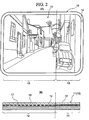
- Fig. 2 includes a front view (A) of the door mirror 10, and a sectional view (B) obtained when cutting a reflecting mirror 11 of the door mirror 10 into two parts along the horizontal direction.
- reference numeral 14 indicates a housing for holding the reflecting mirror 11 and a mirror supporting mechanism (not shown) of the door mirror 10.
- an approximately two-third area, measured from the inner end (closer to the interior of the vehicle) in the vehicle's width direction toward the other end on the opposite side, is defined as a constant curvature part 12 having a substantially constant radius of curvature with respect to the mirror surface, and the remaining area on the outer side in the vehicle's width direction is defined as a gradually-varying curvature part 13, whose radius of curvature gradually decreases toward the outer end (i.e., on the side of the housing 14).
- the main reflecting function of the constant curvature part 12 and the gradually-varying curvature part 3 is implemented by a metal layer 15, which is the bottom (i.e., lowest) layer.
- the entire surface of the reflecting mirror 11 is covered with a glass plate 16.
- a polarizing film 17 and a color filter 18 are provided, which respectively correspond to the constant curvature part 12 and the gradually-varying curvature part 13.
- Fig. 3 is a schematic view for explaining the function of the door mirror 16, when observing a road surface 20, which includes a water film 19 such as a (rain) puddle, through the polarizing film 17 of the constant curvature part 12.
- the polarizing film 17 of the constant curvature part 12 cuts off s-polarized light, included in light which was irregularly reflected by the water film 19 or the like on the road surface 20, thereby reducing reflection on the water film 19 or the like, or relevant glittering.
- the polarizing film 17 of the constant curvature part 12 can also reduce strong sunlight during the day, headlights at night, or diffuse (or irregular) reflection due to light reflected by snow, or the like, thereby improving visibility.
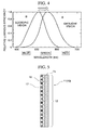
- Fig. 4 shows a relative (or spectral) luminous efficiency curve A with respect to daylight vision, and a relative luminous efficiency curve B with respect to scotopic vision.
- the maximum luminous efficiency is obtained at a wavelength of approximately 555 nm
- the maximum luminous efficiency is obtained at a wavelength of approximately 507 nm.
- the color filter 18 employed in the gradually-varying curvature part 13 has spectral characteristics, whose center wavelength range is set to 500 to 560 nm, in which the relative luminous efficiency is relatively high in either daylight vision or scotopic vision. Therefore, the gradually-varying curvature part 13 can make the relevant occupant recognize a clear and bright reflected image, regardless of day or night, weather conditions, or the like.
- a clear rear visual field which has less distortion and provides a superior sense of distance, can be obtained via the constant curvature part 12, which has a large area and is closer to the interior of the vehicle.
- the polarizing film 17 is provided at the constant curvature part 12, less diffuse reflection occurs, and thus a rear visual field having a high contrast can be provided. Therefore, in the constant curvature part 12, an occupant who looks at the reflecting mirror 11 does not receive much glare, and additionally, the occupant can easily recognize each line or character drawn on the road surface, or a state of the driver (i.e., the driver's eyes or movement) of a vehicle which follows the present vehicle.
- the gradually-varying curvature part 13 has the color filter 18, which has spectral characteristics, whose center wavelength range is set to 500 to 560 nm. Therefore, a bright visual field having a high luminous efficiency can be obtained regardless of daylight or scotopic vision.
- the occupant can easily and accurately judge whether the area which the occupant presently observes belongs to the constant curvature part 12 or the gradually-varying curvature part 13, in accordance with presence or absence of diffuse reflection, and a variation in color.
- parts (A) and (B) show a comparative example (which has been briefly explained before, as a conventional example), in which the constant curvature part 101 and the gradually-varying curvature part 102 are provided, and over the constant curvature part 102 and the gradually-varying curvature part 102, a color filter 105 is provided on a glass plate 104, which covers the front surface of a metal film 103.
- the color filter 105 uniformly reduces light in a wide wavelength range. If coloring concentration of the color filter 105 is increased so as to effectively reduce the glare of light, the entire visual field becomes dark.
- the boundary therebetween is indefinite.
- the boundary therebetween is definite.
- the color filter 18 at the gradually-varying curvature part 13 has spectral characteristics, whose center wavelength range is 500 to 560 nm, a visual field can be obtained, by which the relevant occupant can clearly and easily observe each object, while providing a sufficient effect of reducing the glare of light by means of the gradually-varying curvature part 13.
- the polarizing film 17 and the color filter 18 are each provided on the metal film 15, and the glass plate 16 is further disposed on them.
- the glass plate 16 may be disposed on the metal film 15, and the polarizing film 17 and a color filter (not shown) may be further disposed thereon.
- the polarizing film 17 is provided at the constant curvature part 12 and the color filter 18 is provided at the gradually-varying curvature part 13.
- a variation is possible, in which a polarizing film 17 or a color filter 18 is provided at one of the constant curvature part 12 and the gradually-varying curvature part 13.
- the color filter 18 is provided at the constant curvature part 12 and the polarizing film 17 is provided at the gradually-varying curvature part 13.
- the above embodiment in which not the polarizing film 17 but the color filter 18 is provided on the gradually-varying curvature part 13 in which there is image distortion, is most preferable in consideration of the visibility of each reflected image.
- FIG. 7 A second embodiment of the present invention will be explained below with reference to Figs. 7 and 8 . Similar to the first embodiment, an indirect visual device in accordance with the present invention is applied to a door mirror 10A of a vehicle in the present embodiment.
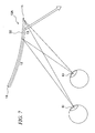
- Fig. 7 is a schematic view for explaining the function of a reflecting mirror 11 in the door mirror 10A.
- the constant curvature part 12 an approximately two-third area, measured from the inner end in the vehicle's width direction toward the other end on the opposite side, is defined as the constant curvature part 12, and the remaining area on the outer side in the vehicle's width direction is defined as the gradually-varying curvature part 13, similar to the first embodiment, whose radius of curvature gradually decreases toward the outer end.
- a color filter 18 is provided at the constant curvature part 12, wherein the filter has spectral characteristics, whose center wavelength range is set to 500 to 560 nm, and (ii) an angular visual field control film 30 is provided at the gradually-varying curvature part 13, wherein the state of the film is switched between visible and invisible states depending on the viewing angle.
- the angular visual field control film 30 is made by incorporating fine light restricting plates, which are inclined at a specific angle, into a film made of PET (poly (ethylene terephthalate)).
- the light restricting plates (not shown) have an inclined angle rotated around the vertical axis with respect to the gradually-varying curvature part 13.
- the light restricting plates incorporated in the angular visual field control film 30 are inclined at an angle which almost matches the viewing angle of an eye of an occupant who sits on the driver's seat, where the eye is distant from the door mirror 10A in comparison with the other eye (of the occupant) which is closer to the door mirror 10A. That is, the light restricting plates are inclined from the viewing angle of the other eye of the occupant.
- the image on the reflecting mirror 11 is visible through the angular visual field control film 30 (i.e., the light restricting plates) from the left eye El of the driver, but is invisible from the right eye Er by means of the angular visual field control film 30 (i.e., the light restricting plates).
- the image on the reflecting mirror 11 is invisible from the left eye El, and is visible only from the right eye Er.
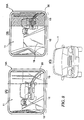
- Fig. 8 includes an image (A) obtained when the driver looks at the door mirror 10A on the right side through the left eye, an image (B) obtained when the driver looks at the same door mirror 10A through the right eye, and an image (C) which is actually recognized through both eyes.
- the reflected image is invisible through the right eye, as shown by the shaded part in the image (B) of Fig. 8 .
- the relevant occupant recognizes a double image (see overlapped images I1 and 12) due to binocular parallax.
- a single image I is always recognized by the relevant occupant.
- a clear rear visual field which has less distortion and provides a superior sense of distance, can be obtained via the constant curvature part 12, which has a large area and is closer to the interior of the vehicle.
- the color filter 18 having spectral characteristics whose center wavelength range is 500 to 560 nm, is provided at the constant curvature part 12, a bright visual field having a high luminous efficiency can be obtained regardless of daylight or scotopic vision.
- a wide-angle visual field from the back to each side of the vehicle can be obtained by means of the gradually-varying curvature part 13.
- the gradually-varying curvature part 13 has the angular visual field control film 30, a clear rear visual field can be obtained, which has no double image (due to binocular parallax) as described above.
- the curvature greatly varies toward the outer end in the width direction of the vehicle. Therefore, images of a target object through the right and left eyes do not coincide with each other, and a double image of the target object must be recognized.
- the door mirror 10A employing the angular visual field control film 30 in the gradually-varying curvature part 13 such a problem can be effectively solved.
- the constant curvature part 12 and the gradually-varying curvature part 13 have different reflection forms from each other by means of the color filter 18 and the angular visual field control film 30. Therefore, the relevant occupant can easily and accurately judge whether the area which the occupant presently observes belongs to the constant curvature part 12 or the gradually-varying curvature part 13.
- the angular visual field control film 30 is invisible from an eye (of the relevant occupant) which is relatively close to the film, while it is visible from the other eye which is relatively distant from the film. Therefore, the occupant can more easily observe a target image.
- the color filter 18 and the angular visual field control film 30 are respectively provided at the constant curvature part 12 and the gradually-varying curvature part 13.
- an angular visual field control film 30 and a color filter 18 may be respectively provided at the constant curvature part 12 and the gradually-varying curvature part 13.
- An indirect visual device (10) of a vehicle includes a reflecting mirror (1) including a constant curvature part (12), which has a substantially constant radius of curvature over the mirror surface, and a gradually-varying curvature part (13), which joins the constant curvature part, and whose radius of curvature gradually decreases toward an end of this part.
- the constant curvature part and the gradually-varying curvature part have different reflection forms from each other.
- a polarizing film (17) is provided at the constant curvature part
- a color filter (18) is provided at the gradually-varying curvature part.
- the color filter has spectral characteristics, whose center wavelength range is 500 to 560 nm.
Landscapes
- Engineering & Computer Science (AREA)
- Multimedia (AREA)
- Mechanical Engineering (AREA)
- Rear-View Mirror Devices That Are Mounted On The Exterior Of The Vehicle (AREA)
- Optical Elements Other Than Lenses (AREA)
Abstract
Description
- The present invention relates to an indirect visual device of a vehicle, for example, a side mirror which provides a side or rear visual field with respect to a vehicle by means of a reflecting mirror.
- Generally, a mirror surface of an indirect visual device (e.g., a side mirror) in a vehicle has a substantially constant radius of curvature. In such an indirect visual device, the visible range obtained by the mirror surface is restricted. Therefore, a modification has been proposed, in which the radius of curvature is partially varied, so as to enlarge the visible range (see, for example,
Japanese Unexamined Patent Application, First Publication No. H8-108800 - As shown in
Fig. 6 , the mirror surface of the disclosed indirect visual device has aconstant curvature part 101, which has a substantially constant radius of curvature, and a gradually-varying curvature part 102, which joins an end of theconstant curvature part 101 and whose radius of curvature gradually decreases toward an end of this part, so as to observe a wide-angle range, which cannot be easily observed via theconstant curvature part 101. - However, in the above conventional indirect visual device, the
constant curvature part 101 and the gradually-varying curvature part 102 are not separated from each other, and the boundary therebetween is visually unclear. Therefore, it is difficult to judge whether each image reflected on the mirror surface is obtained through theconstant curvature part 101 or the gradually-varying curvature part 102, and thus difficult to accurately judge the direction or distance with respect to a subject observed through the mirror surface. - In light of the above circumstances, an object of the present invention is to provide an indirect visual device of a vehicle, for helping an occupant of the vehicle, who looks at a relevant mirror surface, to easily judge whether the occupant observes a subject through a constant curvature part or a gradually-varying curvature part.
- Therefore, the present invention provides an indirect visual device (e.g., a
door mirror - a reflecting mirror (e.g., a
reflecting mirror 11 in the embodiments) including a constant curvature part (e.g., aconstant curvature part 12 in the embodiments), which has a substantially constant radius of curvature over the mirror surface, and a gradually-varying curvature part (e.g., a gradually-varying curvature part 13 in the embodiments), which joins the constant curvature part, and whose radius of curvature gradually decreases toward an end of this part, characterized in that:- the constant curvature part and the gradually-varying curvature part have different reflection forms from each other.
- In accordance with the above structure, as the constant curvature part and the gradually-varying curvature part have different reflection forms from each other, it is possible to easily judge whether the present vision is obtained through the constant curvature part or the gradually-varying curvature part on the mirror surface, in accordance with the difference in the reflection form. Therefore, the occupant can more accurately perform judgment based on the present vision through the indirect visual device.
- In a typical example, a polarizing film (e.g., a polarizing
film 17 in the first embodiment) is provided at one of the constant curvature part and the gradually-varying curvature part. Accordingly, diffuse reflection can be removed using the polarizing film, thereby effectively reducing the glare of light. In addition, the occupant can easily judge whether the area (on the reflecting mirror) which the occupant presently observes belongs to the constant curvature part or the gradually-varying curvature part, in accordance with presence or absence of diffuse reflection. - Preferably, the polarizing film may be provided at the constant curvature part. In this case, major indirect vision by means of the constant curvature part can be a clear vision without diffuse reflection, through the polarizing film. In addition, it is possible to remove inconvenience in occupant's observation due to a combination of the gradually-varying curvature part and the polarizing film.
- In another typical example, a color filter (e.g., a
color filter 18 in the embodiments) is provided at one of the constant curvature part and the gradually-varying curvature part. Accordingly, the wavelength of the reflected light can be converted through the color filter, thereby improving easiness in occupant's observation, and the occupant can easily judge whether the area (on the reflecting mirror) which the occupant presently observes belongs to the constant curvature part or the gradually-varying curvature part, in accordance with a variation in color. - Preferably, the color filter is provided at the gradually-varying curvature part. In this case, a peripheral visual field, which is reflected in the gradually-varying curvature part and has a distortion, can be more easily recognized.
- In a preferable example:
- a polarizing film (e.g., a polarizing
film 17 in the first embodiment) is provided at the constant curvature part; and - a color filter (e.g., a
color filter 18 in the first embodiment) is provided at the gradually-varying curvature part. - Accordingly, diffuse reflection in the constant curvature part can be removed, and simultaneously, in the gradually-varying curvature part, the wavelength of the reflected light can be converted through the color filter. Additionally, the occupant can more easily judge whether the area (on the reflecting mirror) which the occupant presently observes belongs to the constant curvature part or the gradually-varying curvature part, in accordance with presence or absence of diffuse reflection, and a variation in color.
- Typically, the color filter has spectral characteristics, whose center wavelength range is 500 to 560 nm. Such a color filter has a high luminous efficiency regardless of daylight or scotopic vision, and thus it can make the occupant recognize a clear and bright image reflected in the reflecting mirror, regardless of day or night, weather conditions, or the like.
- In another typical example, an angular visual field control film (e.g., an angular visual
field control film 30 in the second embodiment), whose state is switched between visible and invisible states depending on the viewing angle, is provided at one of the constant curvature part and the gradually-varying curvature part; and
the angular visual field control film is arranged in such a manner that it is visible from one of the eyes of an occupant of the vehicle, but is invisible from the other eye of the occupant. - Generally, when one of the constant curvature part and the gradually-varying curvature part is observed using the right and left eyes, a reflected image may become a double image due to binocular parallax. However, in such a case, vision through one of the eyes can be ineffective through the angular visual field control film, so that the reflected image observed by the relevant occupant can be a clear single image.
- Preferably, the angular visual field control film is provided at the gradually-varying curvature part. In this case, major indirect vision through the constant curvature part is reliably obtained using both eyes, and only a peripheral visual field through the gradually-varying curvature part is recognized through a single eye. Therefore, a rear visual field can be more easily observed.
- In the above structure, a color filter (e.g., a
color filter 18 in the second embodiment) may be provided at the constant curvature part. Accordingly, it is possible to prevent a double image at the gradually-varying curvature part through both eyes by using the angular visual field control film, and simultaneously, the occupant can more easily judge whether the area (on the reflecting mirror) which the occupant presently observes belongs to the constant curvature part or the gradually-varying curvature part, in accordance with a variation in color. - Preferably, the color filter has spectral characteristics, whose center wavelength range is 500 to 560 nm.
- When providing the above angular visual field control film, it is possible that:
- the indirect visual device is a door mirror (10A) provided at each of the right and left sides of the vehicle;
- when the occupant looks at the door mirror on the right side, the angular visual field control film is visible from the left eye of the occupant, but is invisible from the right eye of the occupant; and
- when the occupant looks at the door mirror on the left side, the angular visual field control film is visible from the right eye of the occupant, but is invisible from the left eye of the occupant.
- Accordingly, the angular visual field control film used in the reflecting mirror of each door mirror is invisible from an eye (of the occupant) which is relatively close to the film, but is visible from the other eye which is relatively distant from the film. Therefore, the occupant can more easily observe and recognize a target image.
-
-
Fig. 1 is a perspective view showing a first embodiment of the indirect visual device in accordance with the present invention. -
Fig. 2 includes a front view (A) and a sectional view (B) of the indirect visual device in the first embodiment. -
Fig. 3 is a schematic diagram for explaining the function of a polarizing film used in the first embodiment. -
Fig. 4 is a graph showing a relative luminous efficiency curve with respect to daylight vision, and a relative luminous efficiency curve with respect to scotopic vision. -
Fig. 5 is a sectional view showing a part of the structure as a variation of the first embodiment. -
Fig. 6 includes a front view (A) and a sectional view (B) of an indirect visual device as a comparative example. -
Fig. 7 is a schematic view for explaining the function of an indirect visual device as a second embodiment in accordance with the present invention. -
Fig. 8 is a diagram including an image (A) obtained when the driver looks at the indirect visual device of the second embodiment through the left eye, an image (B) obtained when the driver looks at the same device through the right eye, and an image (C) which is actually recognized through both eyes. -
Fig. 9 is a diagram including an image (A) obtained when the driver looks at an indirect visual device as a comparative example through the left eye, an image (B) obtained when the driver looks at the same device through the right eye, and an image (C) which is actually recognized through both eyes. - Hereinafter, embodiments in accordance with the present invention will be described with reference to the appended figures. In the following explanation, directions such as a vertical or front-to-back direction are defined with respect to the vehicle's travel direction when no specific comment is provided.
- A first embodiment will be explained below with reference to
Figs. 1 to 4 . -
Fig. 1 is a perspective view of a part in a vehicle, which employs adoor mirror 10 as a first embodiment of the indirect visual device in accordance with the present invention.Fig. 2 includes a front view (A) of thedoor mirror 10, and a sectional view (B) obtained when cutting a reflectingmirror 11 of thedoor mirror 10 into two parts along the horizontal direction. InFig. 2 ,reference numeral 14 indicates a housing for holding the reflectingmirror 11 and a mirror supporting mechanism (not shown) of thedoor mirror 10. - As shown in
Fig. 2 , in the reflectingmirror 11 of thedoor mirror 10, an approximately two-third area, measured from the inner end (closer to the interior of the vehicle) in the vehicle's width direction toward the other end on the opposite side, is defined as aconstant curvature part 12 having a substantially constant radius of curvature with respect to the mirror surface, and the remaining area on the outer side in the vehicle's width direction is defined as a gradually-varyingcurvature part 13, whose radius of curvature gradually decreases toward the outer end (i.e., on the side of the housing 14). - As shown in part (B) of
Fig. 2 , in the reflectingmirror 11, the main reflecting function of theconstant curvature part 12 and the gradually-varying curvature part 3 is implemented by ametal layer 15, which is the bottom (i.e., lowest) layer. The entire surface of the reflectingmirror 11 is covered with aglass plate 16. Between themetal layer 15 and theglass plate 16, apolarizing film 17 and acolor filter 18 are provided, which respectively correspond to theconstant curvature part 12 and the gradually-varyingcurvature part 13. -
Fig. 3 is a schematic view for explaining the function of thedoor mirror 16, when observing aroad surface 20, which includes awater film 19 such as a (rain) puddle, through thepolarizing film 17 of theconstant curvature part 12. As shown inFig. 3 , thepolarizing film 17 of theconstant curvature part 12 cuts off s-polarized light, included in light which was irregularly reflected by thewater film 19 or the like on theroad surface 20, thereby reducing reflection on thewater film 19 or the like, or relevant glittering. Thepolarizing film 17 of theconstant curvature part 12 can also reduce strong sunlight during the day, headlights at night, or diffuse (or irregular) reflection due to light reflected by snow, or the like, thereby improving visibility. -
Fig. 4 shows a relative (or spectral) luminous efficiency curve A with respect to daylight vision, and a relative luminous efficiency curve B with respect to scotopic vision. As shown inFig. 4 , with respect to daylight vision, the maximum luminous efficiency is obtained at a wavelength of approximately 555 nm, while with respect to scotopic vision, the maximum luminous efficiency is obtained at a wavelength of approximately 507 nm. - The
color filter 18 employed in the gradually-varyingcurvature part 13 has spectral characteristics, whose center wavelength range is set to 500 to 560 nm, in which the relative luminous efficiency is relatively high in either daylight vision or scotopic vision. Therefore, the gradually-varyingcurvature part 13 can make the relevant occupant recognize a clear and bright reflected image, regardless of day or night, weather conditions, or the like. - In the
door mirror 10 having the above-described structure, a clear rear visual field, which has less distortion and provides a superior sense of distance, can be obtained via theconstant curvature part 12, which has a large area and is closer to the interior of the vehicle. In addition, as thepolarizing film 17 is provided at theconstant curvature part 12, less diffuse reflection occurs, and thus a rear visual field having a high contrast can be provided. Therefore, in theconstant curvature part 12, an occupant who looks at the reflectingmirror 11 does not receive much glare, and additionally, the occupant can easily recognize each line or character drawn on the road surface, or a state of the driver (i.e., the driver's eyes or movement) of a vehicle which follows the present vehicle. - Also in the
door mirror 10, a wide-angle visual field from the back to each side of the vehicle can be obtained by means of the gradually-varyingcurvature part 13. In addition, the gradually-varyingcurvature part 13 has thecolor filter 18, which has spectral characteristics, whose center wavelength range is set to 500 to 560 nm. Therefore, a bright visual field having a high luminous efficiency can be obtained regardless of daylight or scotopic vision. - Furthermore, in the
door mirror 10, as thepolarizing film 17 is provided at theconstant curvature part 12 and thecolor filter 18 is provided at the gradually-varyingcurvature part 13, the occupant can easily and accurately judge whether the area which the occupant presently observes belongs to theconstant curvature part 12 or the gradually-varyingcurvature part 13, in accordance with presence or absence of diffuse reflection, and a variation in color. - In
Fig. 6 , parts (A) and (B) show a comparative example (which has been briefly explained before, as a conventional example), in which theconstant curvature part 101 and the gradually-varyingcurvature part 102 are provided, and over theconstant curvature part 102 and the gradually-varyingcurvature part 102, acolor filter 105 is provided on aglass plate 104, which covers the front surface of ametal film 103. Thecolor filter 105 uniformly reduces light in a wide wavelength range. If coloring concentration of thecolor filter 105 is increased so as to effectively reduce the glare of light, the entire visual field becomes dark. In addition, as thecolor filter 105 is continuously provided over theconstant curvature part 101 and the gradually-varyingcurvature part 102, the boundary therebetween is indefinite. - In contrast, in the
door mirror 10 of the present embodiment, as thecolor filter 18 is provided at the gradually-varyingcurvature part 13, and thepolarizing film 17 is provided at theconstant curvature part 12, the boundary therebetween is definite. Furthermore, as thecolor filter 18 at the gradually-varyingcurvature part 13 has spectral characteristics, whose center wavelength range is 500 to 560 nm, a visual field can be obtained, by which the relevant occupant can clearly and easily observe each object, while providing a sufficient effect of reducing the glare of light by means of the gradually-varyingcurvature part 13. - In the reflecting
mirror 11 of the above embodiment, thepolarizing film 17 and thecolor filter 18 are each provided on themetal film 15, and theglass plate 16 is further disposed on them. Instead, as shown inFig. 5 , which shows a part of the structure as a variation of this embodiment, theglass plate 16 may be disposed on themetal film 15, and thepolarizing film 17 and a color filter (not shown) may be further disposed thereon. Also in the above embodiment, thepolarizing film 17 is provided at theconstant curvature part 12 and thecolor filter 18 is provided at the gradually-varyingcurvature part 13. However, a variation is possible, in which apolarizing film 17 or acolor filter 18 is provided at one of theconstant curvature part 12 and the gradually-varyingcurvature part 13. In another variation, thecolor filter 18 is provided at theconstant curvature part 12 and thepolarizing film 17 is provided at the gradually-varyingcurvature part 13. However, the above embodiment, in which not thepolarizing film 17 but thecolor filter 18 is provided on the gradually-varyingcurvature part 13 in which there is image distortion, is most preferable in consideration of the visibility of each reflected image. - A second embodiment of the present invention will be explained below with reference to
Figs. 7 and8 . Similar to the first embodiment, an indirect visual device in accordance with the present invention is applied to adoor mirror 10A of a vehicle in the present embodiment. -
Fig. 7 is a schematic view for explaining the function of a reflectingmirror 11 in thedoor mirror 10A. As shown inFig. 7 , in the reflectingmirror 11 of thedoor mirror 10A, an approximately two-third area, measured from the inner end in the vehicle's width direction toward the other end on the opposite side, is defined as theconstant curvature part 12, and the remaining area on the outer side in the vehicle's width direction is defined as the gradually-varyingcurvature part 13, similar to the first embodiment, whose radius of curvature gradually decreases toward the outer end. - In the reflecting
mirror 11, (i) acolor filter 18 is provided at theconstant curvature part 12, wherein the filter has spectral characteristics, whose center wavelength range is set to 500 to 560 nm, and (ii) an angular visualfield control film 30 is provided at the gradually-varyingcurvature part 13, wherein the state of the film is switched between visible and invisible states depending on the viewing angle. - The angular visual
field control film 30 is made by incorporating fine light restricting plates, which are inclined at a specific angle, into a film made of PET (poly (ethylene terephthalate)). In the present embodiment, the light restricting plates (not shown) have an inclined angle rotated around the vertical axis with respect to the gradually-varyingcurvature part 13. - More specifically, the light restricting plates incorporated in the angular visual
field control film 30 are inclined at an angle which almost matches the viewing angle of an eye of an occupant who sits on the driver's seat, where the eye is distant from thedoor mirror 10A in comparison with the other eye (of the occupant) which is closer to thedoor mirror 10A. That is, the light restricting plates are inclined from the viewing angle of the other eye of the occupant. - For example, as shown in
Fig. 7 , with respect to thedoor mirror 10A on the right side with respect to the driver's seat, the image on the reflectingmirror 11 is visible through the angular visual field control film 30 (i.e., the light restricting plates) from the left eye El of the driver, but is invisible from the right eye Er by means of the angular visual field control film 30 (i.e., the light restricting plates). In contrast, with respect to thedoor mirror 10A on the left side, the image on the reflectingmirror 11 is invisible from the left eye El, and is visible only from the right eye Er. -
Fig. 8 includes an image (A) obtained when the driver looks at thedoor mirror 10A on the right side through the left eye, an image (B) obtained when the driver looks at thesame door mirror 10A through the right eye, and an image (C) which is actually recognized through both eyes. - In the gradually-varying
curvature part 13 at which the angular visualfield control film 30 is provided, the reflected image is invisible through the right eye, as shown by the shaded part in the image (B) ofFig. 8 . When such an angular visualfield control film 30 is not provided at the gradually-varying curvature part 13 (see a comparative example shown inFig. 9 ), the relevant occupant recognizes a double image (see overlapped images I1 and 12) due to binocular parallax. However, in the present embodiment, as the visual field of one of the eyes through the gradually-varyingcurvature part 13 is blocked by the angular visualfield control film 30, a single image I is always recognized by the relevant occupant. - Therefore, in the
door mirror 10A of the present invention, a clear rear visual field, which has less distortion and provides a superior sense of distance, can be obtained via theconstant curvature part 12, which has a large area and is closer to the interior of the vehicle. In addition, as thecolor filter 18 having spectral characteristics, whose center wavelength range is 500 to 560 nm, is provided at theconstant curvature part 12, a bright visual field having a high luminous efficiency can be obtained regardless of daylight or scotopic vision. - Also in the
door mirror 10A, a wide-angle visual field from the back to each side of the vehicle can be obtained by means of the gradually-varyingcurvature part 13. In addition, the gradually-varyingcurvature part 13 has the angular visualfield control film 30, a clear rear visual field can be obtained, which has no double image (due to binocular parallax) as described above. - In particular, in the gradually-varying
curvature part 13, the curvature greatly varies toward the outer end in the width direction of the vehicle. Therefore, images of a target object through the right and left eyes do not coincide with each other, and a double image of the target object must be recognized. However, in thedoor mirror 10A employing the angular visualfield control film 30 in the gradually-varyingcurvature part 13, such a problem can be effectively solved. - Therefore, when employing the
door mirror 10A, it is possible to reliably relieve a mental stress or eye fatigue of the driver, produced when looking at the gradually-varyingcurvature part 13. - Also in the present embodiment, the
constant curvature part 12 and the gradually-varyingcurvature part 13 have different reflection forms from each other by means of thecolor filter 18 and the angular visualfield control film 30. Therefore, the relevant occupant can easily and accurately judge whether the area which the occupant presently observes belongs to theconstant curvature part 12 or the gradually-varyingcurvature part 13. - In addition, in the
door mirror 10A of the present embodiment, the angular visualfield control film 30 is invisible from an eye (of the relevant occupant) which is relatively close to the film, while it is visible from the other eye which is relatively distant from the film. Therefore, the occupant can more easily observe a target image. - In the present embodiment, the
color filter 18 and the angular visualfield control film 30 are respectively provided at theconstant curvature part 12 and the gradually-varyingcurvature part 13. However, an angular visualfield control film 30 and acolor filter 18 may be respectively provided at theconstant curvature part 12 and the gradually-varyingcurvature part 13. - When respectively providing the
color filter 18 and the angular visualfield control film 30 at theconstant curvature part 12 and the gradually-varyingcurvature part 13 as in the present embodiment, major indirect vision through theconstant curvature part 12 can be reliably obtained using both eyes, and only a peripheral visual field through the gradually-varyingcurvature part 13 is recognized through a single eye. Therefore, a rear visual field through thedoor mirror 10A can be more easily observed. - While preferred embodiments of the invention have been described and illustrated above, it should be understood that these are exemplary of the invention and are not to be considered as limiting. Additions, omissions, substitutions, and other modifications can be made without departing from the scope of the present invention. Accordingly, the invention is not to be considered as being limited by the foregoing description, and is only limited by the scope of the appended claims.
- An indirect visual device (10) of a vehicle, includes a reflecting mirror (1) including a constant curvature part (12), which has a substantially constant radius of curvature over the mirror surface, and a gradually-varying curvature part (13), which joins the constant curvature part, and whose radius of curvature gradually decreases toward an end of this part. The constant curvature part and the gradually-varying curvature part have different reflection forms from each other. Preferably, a polarizing film (17) is provided at the constant curvature part, and a color filter (18) is provided at the gradually-varying curvature part. Typically, the color filter has spectral characteristics, whose center wavelength range is 500 to 560 nm.
Claims (12)
- An indirect visual device (10; 10A) of a vehicle, comprising:a reflecting mirror (1) including a constant curvature part (12), which has a substantially constant radius of curvature over the mirror surface, and a gradually-varying curvature part (13), which joins the constant curvature part, and whose radius of curvature gradually decreases toward an end of this part, characterized in that:the constant curvature part and the gradually-varying curvature part have different reflection forms from each other.
- The indirect visual device in accordance with Claim 1, characterized in that:a polarizing film (17) is provided at one of the constant curvature part and the gradually-varying curvature part.
- The indirect visual device in accordance with Claim 2, characterized in that:the polarizing film is provided at the constant curvature part.
- The indirect visual device in accordance with Claim 1, characterized in that:a color filter (18) is provided at one of the constant curvature part and the gradually-varying curvature part.
- The indirect visual device in accordance with Claim 4, characterized in that:the color filter is provided at the gradually-varying curvature part.
- The indirect visual device in accordance with Claim 1, characterized in that:a polarizing film (17) is provided at the constant curvature part; anda color filter (18) is provided at the gradually-varying curvature part.
- The indirect visual device in accordance with any one of Claims 4 to 6, characterized in that:the color filter has spectral characteristics, whose center wavelength range is 500 to 560 nm.
- The indirect visual device in accordance with Claim 1, characterized in that:an angular visual field control film (30), whose state is switched between visible and invisible states depending on the viewing angle, is provided at one of the constant curvature part and the gradually-varying curvature part; andthe angular visual field control film is arranged in such a manner that it is visible from one of the eyes of an occupant of the vehicle, but is invisible from the other eye of the occupant.
- The indirect visual device in accordance with Claim 8, characterized in that:the angular visual field control film is provided at the gradually-varying curvature part.
- The indirect visual device in accordance with Claim 9, characterized in that:a color filter (18) is provided at the constant curvature part.
- The indirect visual device in accordance with Claim 10, characterized in that:the color filter has spectral characteristics, whose center wavelength range is 500 to 560 nm.
- The indirect visual device in accordance with any one of Claims 8 to 10, characterized in that:the indirect visual device is a door mirror (10A) provided at each of the right and left sides of the vehicle;when the occupant looks at the door mirror on the right side, the angular visual field control film is visible from the left eye of the occupant, but is invisible from the right eye of the occupant; andwhen the occupant looks at the door mirror on the left side, the angular visual field control film is visible from the right eye of the occupant, but is invisible from the left eye of the occupant.
Applications Claiming Priority (2)
| Application Number | Priority Date | Filing Date | Title |
|---|---|---|---|
| JP2006341301 | 2006-12-19 | ||
| JP2007311353A JP2008174219A (en) | 2006-12-19 | 2007-11-30 | Indirect vehicle viewing device |
Publications (2)
| Publication Number | Publication Date |
|---|---|
| EP1935721A1 true EP1935721A1 (en) | 2008-06-25 |
| EP1935721B1 EP1935721B1 (en) | 2009-12-02 |
Family
ID=39273201
Family Applications (1)
| Application Number | Title | Priority Date | Filing Date |
|---|---|---|---|
| EP20070024417 Ceased EP1935721B1 (en) | 2006-12-19 | 2007-12-17 | Indirect visual device of vehicle |
Country Status (1)
| Country | Link |
|---|---|
| EP (1) | EP1935721B1 (en) |
Cited By (1)
| Publication number | Priority date | Publication date | Assignee | Title |
|---|---|---|---|---|
| WO2010094702A1 (en) * | 2009-02-18 | 2010-08-26 | Mekra Lang Gmbh & Co. Kg. | Mirror assembly for vehicles and vehicle having said mirror assembly |
Citations (5)
| Publication number | Priority date | Publication date | Assignee | Title |
|---|---|---|---|---|
| DE2552267A1 (en) * | 1975-11-21 | 1977-06-02 | Arthur Seibert | Two lens driving mirror - has blind spot area reduced by partly silvered glass over main mirror |
| DE2915580A1 (en) * | 1979-04-18 | 1980-10-30 | Walter Rieder | Motor vehicle rear view mirror - has spherically curved portion offset relative to flat surface for traffic passing nearby in blind area |
| DE19627417C1 (en) * | 1996-07-08 | 1997-10-23 | Daimler Benz Ag | External rear view mirror for motor vehicle |
| US20040190166A1 (en) * | 2000-01-06 | 2004-09-30 | Donnelly Corporation, A Corporation Of The State Of Michigan | Exterior mirror plano-auxiliary reflective element assembly |
| US20050083577A1 (en) * | 1994-05-05 | 2005-04-21 | Donnelly Corporation | Electrochromic mirrors and devices |
-
2007
- 2007-12-17 EP EP20070024417 patent/EP1935721B1/en not_active Ceased
Patent Citations (5)
| Publication number | Priority date | Publication date | Assignee | Title |
|---|---|---|---|---|
| DE2552267A1 (en) * | 1975-11-21 | 1977-06-02 | Arthur Seibert | Two lens driving mirror - has blind spot area reduced by partly silvered glass over main mirror |
| DE2915580A1 (en) * | 1979-04-18 | 1980-10-30 | Walter Rieder | Motor vehicle rear view mirror - has spherically curved portion offset relative to flat surface for traffic passing nearby in blind area |
| US20050083577A1 (en) * | 1994-05-05 | 2005-04-21 | Donnelly Corporation | Electrochromic mirrors and devices |
| DE19627417C1 (en) * | 1996-07-08 | 1997-10-23 | Daimler Benz Ag | External rear view mirror for motor vehicle |
| US20040190166A1 (en) * | 2000-01-06 | 2004-09-30 | Donnelly Corporation, A Corporation Of The State Of Michigan | Exterior mirror plano-auxiliary reflective element assembly |
Cited By (2)
| Publication number | Priority date | Publication date | Assignee | Title |
|---|---|---|---|---|
| WO2010094702A1 (en) * | 2009-02-18 | 2010-08-26 | Mekra Lang Gmbh & Co. Kg. | Mirror assembly for vehicles and vehicle having said mirror assembly |
| JP2012517929A (en) * | 2009-02-18 | 2012-08-09 | メクラ・ラング・ゲーエムベーハー・ウント・コー・カーゲー | Mirror assembly for vehicle and vehicle including mirror assembly |
Also Published As
| Publication number | Publication date |
|---|---|
| EP1935721B1 (en) | 2009-12-02 |
Similar Documents
| Publication | Publication Date | Title |
|---|---|---|
| KR101011507B1 (en) | Vehicle rearview mirror assembly with high intensity display | |
| US7970172B1 (en) | Electrically controlled optical shield for eye protection against bright light | |
| US11084357B2 (en) | Sun shield | |
| US10649299B2 (en) | Electro-optic assembly | |
| US9302568B2 (en) | Sun tracking tint visor | |
| US12534021B2 (en) | Vehicular driver monitoring system with eye tracking | |
| US20150367714A1 (en) | Sun Tracking Tint Visor | |
| US6056397A (en) | Method and apparatus for reducing glare while driving | |
| WO2023030794A1 (en) | Display screen, and display system for a panoramic display unit | |
| CN101954882A (en) | On-vehicle multidirectional visual-recognition device | |
| EP1935721B1 (en) | Indirect visual device of vehicle | |
| KR100969307B1 (en) | Car rearview mirror | |
| DE102019112449B4 (en) | Motor vehicle with an optical arrangement for detecting interior objects in the invisible spectral range | |
| CN204383302U (en) | Camera inside rear-view mirror | |
| CN118163583A (en) | Windshields, Head-Up Displays and Vehicles | |
| US3738737A (en) | Antiglare safety rearview mirror for automotive vehicles | |
| US9415573B2 (en) | Light filtering translucent film for vehicle mirror | |
| JP2012517929A (en) | Mirror assembly for vehicle and vehicle including mirror assembly | |
| JP2008174219A (en) | Indirect vehicle viewing device | |
| CN114763055A (en) | Anti-glare system and method | |
| KR200363972Y1 (en) | Sunglass for vehicles with day and night | |
| JP2009056966A (en) | On-vehicle mirror | |
| WO2024184391A1 (en) | Projection arrangement | |
| EP4649350A1 (en) | Projection arrangement | |
| CN115402065A (en) | Light quantity adjusting method and system and automobile |
Legal Events
| Date | Code | Title | Description |
|---|---|---|---|
| PUAI | Public reference made under article 153(3) epc to a published international application that has entered the european phase |
Free format text: ORIGINAL CODE: 0009012 |
|
| 17P | Request for examination filed |
Effective date: 20071217 |
|
| AK | Designated contracting states |
Kind code of ref document: A1 Designated state(s): AT BE BG CH CY CZ DE DK EE ES FI FR GB GR HU IE IS IT LI LT LU LV MC MT NL PL PT RO SE SI SK TR |
|
| AX | Request for extension of the european patent |
Extension state: AL BA HR MK RS |
|
| 17Q | First examination report despatched |
Effective date: 20080624 |
|
| AKX | Designation fees paid |
Designated state(s): DE GB |
|
| GRAP | Despatch of communication of intention to grant a patent |
Free format text: ORIGINAL CODE: EPIDOSNIGR1 |
|
| GRAS | Grant fee paid |
Free format text: ORIGINAL CODE: EPIDOSNIGR3 |
|
| RAP1 | Party data changed (applicant data changed or rights of an application transferred) |
Owner name: HONDA MOTOR CO., LTD. |
|
| GRAA | (expected) grant |
Free format text: ORIGINAL CODE: 0009210 |
|
| AK | Designated contracting states |
Kind code of ref document: B1 Designated state(s): DE GB |
|
| REG | Reference to a national code |
Ref country code: GB Ref legal event code: FG4D |
|
| REF | Corresponds to: |
Ref document number: 602007003547 Country of ref document: DE Date of ref document: 20100114 Kind code of ref document: P |
|
| PLBE | No opposition filed within time limit |
Free format text: ORIGINAL CODE: 0009261 |
|
| STAA | Information on the status of an ep patent application or granted ep patent |
Free format text: STATUS: NO OPPOSITION FILED WITHIN TIME LIMIT |
|
| 26N | No opposition filed |
Effective date: 20100903 |
|
| REG | Reference to a national code |
Ref country code: DE Ref legal event code: R084 Ref document number: 602007003547 Country of ref document: DE |
|
| REG | Reference to a national code |
Ref country code: GB Ref legal event code: 746 Effective date: 20140813 |
|
| REG | Reference to a national code |
Ref country code: DE Ref legal event code: R084 Ref document number: 602007003547 Country of ref document: DE Effective date: 20140821 |
|
| PGFP | Annual fee paid to national office [announced via postgrant information from national office to epo] |
Ref country code: GB Payment date: 20141217 Year of fee payment: 8 Ref country code: DE Payment date: 20141209 Year of fee payment: 8 |
|
| REG | Reference to a national code |
Ref country code: DE Ref legal event code: R119 Ref document number: 602007003547 Country of ref document: DE |
|
| GBPC | Gb: european patent ceased through non-payment of renewal fee |
Effective date: 20151217 |
|
| PG25 | Lapsed in a contracting state [announced via postgrant information from national office to epo] |
Ref country code: DE Free format text: LAPSE BECAUSE OF NON-PAYMENT OF DUE FEES Effective date: 20160701 Ref country code: GB Free format text: LAPSE BECAUSE OF NON-PAYMENT OF DUE FEES Effective date: 20151217 |