EP1934126B1 - Counterweight with partially imbedded buffer - Google Patents
Counterweight with partially imbedded buffer Download PDFInfo
- Publication number
- EP1934126B1 EP1934126B1 EP05807666A EP05807666A EP1934126B1 EP 1934126 B1 EP1934126 B1 EP 1934126B1 EP 05807666 A EP05807666 A EP 05807666A EP 05807666 A EP05807666 A EP 05807666A EP 1934126 B1 EP1934126 B1 EP 1934126B1
- Authority
- EP
- European Patent Office
- Prior art keywords
- counterweight
- fillers
- buffer
- buffer member
- outer boundary
- Prior art date
- Legal status (The legal status is an assumption and is not a legal conclusion. Google has not performed a legal analysis and makes no representation as to the accuracy of the status listed.)
- Expired - Lifetime
Links
Images
Classifications
-
- B—PERFORMING OPERATIONS; TRANSPORTING
- B66—HOISTING; LIFTING; HAULING
- B66B—ELEVATORS; ESCALATORS OR MOVING WALKWAYS
- B66B5/00—Applications of checking, fault-correcting, or safety devices in elevators
- B66B5/28—Buffer-stops for cars, cages, or skips
- B66B5/284—Buffer-stops for cars, cages, or skips mounted on cars or counterweights
- B66B5/286—Buffer-stops for cars, cages, or skips mounted on cars or counterweights between two cars or two counterweights
-
- B—PERFORMING OPERATIONS; TRANSPORTING
- B66—HOISTING; LIFTING; HAULING
- B66B—ELEVATORS; ESCALATORS OR MOVING WALKWAYS
- B66B17/00—Hoistway equipment
- B66B17/12—Counterpoises
Definitions
- This invention generally relates to elevator systems. More particularly, this invention relates to a counterweight and buffer arrangement for use in an elevator system.
- Many elevator systems includes a car and counterweight coupled together by a rope or other load bearing member such as a belt.
- a machine controls movement of the car to service passengers between various levels in a building, for example.
- the counterweight and car typically move in opposite directions within a hoistway.
- U.S. Patent No. 1,896,776 shows buffers carried by the counterweights and cars for absorbing impact between the counterweights or the cars, respectively.
- One disadvantage to such an arrangement is that the buffers increase the envelope of the counterweights, the cars or both. Doing so takes up additional hoistway space, which is at a premium.
- the position of buffers as shown in that patent hinders the ability to position the elevator cars at immediately adjacent floors, for example.
- Counterweights having projecting buffers are disclosed in EP-A-1882667 and WO 2006/062499 , which form prior art under Art. 54(3) EPC.
- a counterweight having the features of the preamble of claim 1 is disclosed in US-A-1896776 .
- An elevator having a projecting buffer is disclosed in JP-A-2001 163543 .
- a counterweight in accordance with the invention is set forth in claim 1.
- the second portion of the buffer member beyond the outer boundary that is moveable relative to the first portion absorbs energy associated with contact with another counterweight.
- some of the fillers have a dimension that allows them to fit along side the first portion of the buffer member. This allows for a more compact counterweight design compared to one that relies upon fillers that extend across an entire width dimension of the frame.
- FIG. 1 schematically shows selected portions of an elevator system 20.
- a first elevator car 22 is coupled with a first counterweight for movement within a hoistway 26.
- the first elevator car 22 is coupled to the first counterweight 24 by a plurality of ropes or belts as known.
- a second elevator car 32 is positioned below (according to the drawing) the first elevator car 22.
- the second elevator car 32 is associated with a second counterweight 34 by a load bearing member (not shown) so that both move within the hoistway 26 as known.
- the counterweights 24 and 34 travel along common guide rails 36. In other words, the counterweights 24 and 34 share the same guide rails 36.
- At least one buffer member 40 is supported on at least one of the counterweights 24 or 34 to absorb impact associated with the counterweights contacting each other.
- Figure 2 schematically shows one example embodiment of a counterweight 24 having a buffer member 40 that is supported by the counterweight for movement with the counterweight within the hoistway 26.
- the counterweight 24 has a structure 42 that defines an outer boundary of the counterweight.
- the structure 42 comprises a frame that is made in a generally known manner.
- the outer boundary defined by the structure 42 includes a height dimension H and a width dimension W.
- the illustrated example includes guide supports 44 that are outside of the outer boundary in this example.
- the guide supports 44 may be within the outer boundary, depending on the configuration of the counterweight structure.
- the guide supports operate in a known manner to facilitate moving the counterweight along the guide rails 36.
- the buffer member 40 has a first portion 52 that is within the outer boundary of the counterweight structure 42. A second portion 54 is beyond the outer boundary.
- a distal end 56 of the buffer member 40 is adapted to contact the other counterweight (i.e., the counterweight 34) before the counterweight structures would contact each other.
- the buffer member 40 has cooperating cylinders that operate in a known manner (i.e., hydraulic) to provide an energy absorbing function in the event that the counterweights move close enough to contact each other.
- the frame 42 supports a plurality of fillers 60.
- the fillers comprise plates as known.
- the fillers 60 have a lateral dimension that corresponds to the width W of the structure 42.
- the term "lateral" as used in this description refers to a direction taken in the width W direction as shown in the drawings.
- the size of the frame members and the size of the fillers 60 fit within the outer boundary of the counterweight 24.
- the example of Figure 2 also includes a plurality of second filler members 62 that have a second, smaller lateral dimension.
- two sets of second filler members 62 are provided, one on either lateral side of the first portion 52 of the buffer member 40. Accordingly, the filler members 62 have a dimension that corresponds to a difference between the width of the structure 42 and a width of the first portion 52 of the buffer member 40.
- Figure 3 shows another example including two buffer members 40.
- the latter includes one set of second fillers 62 positioned between the buffer members 40.
- the smaller, second fillers 62 provide for establishing a desired counterweight mass without increasing the height of the counterweight.
- the space within the outer boundary occupied by the first portion 52 of the buffer member 40 in the height direction may also be occupied by smaller fillers.
- both counterweights may include at least one buffer member.
- the arrangements and placement of the buffer member or members will depend, in part, on a selected roping arrangement. Those skilled in the art who have the benefit of this description will be able to select an appropriate arrangement to meet their particular needs.
Landscapes
- Maintenance And Inspection Apparatuses For Elevators (AREA)
- Cage And Drive Apparatuses For Elevators (AREA)
Description
- This invention generally relates to elevator systems. More particularly, this invention relates to a counterweight and buffer arrangement for use in an elevator system.
- Many elevator systems includes a car and counterweight coupled together by a rope or other load bearing member such as a belt. A machine controls movement of the car to service passengers between various levels in a building, for example. As known, the counterweight and car typically move in opposite directions within a hoistway.
- It has been proposed to include multiple elevator cars within a single hoistway. Such an arrangement provides advantages for increased or improved passenger service, for example.
U.S. Patent No. 1,896,776 is an example patent pertaining to an elevator system having multiple cars within a hoistway. - There are various challenges presented when trying to provide multiple cars in a hoistway. For example, the increased number of components generates needs for different types of safety devices.
U.S. Patent No. 1,896,776 , for example, shows buffers carried by the counterweights and cars for absorbing impact between the counterweights or the cars, respectively. One disadvantage to such an arrangement is that the buffers increase the envelope of the counterweights, the cars or both. Doing so takes up additional hoistway space, which is at a premium. Moreover, the position of buffers as shown in that patent hinders the ability to position the elevator cars at immediately adjacent floors, for example. - There is a need for an arrangement that provides a buffer feature in a cost-efficient and space-efficient manner. This invention addresses that need.
- Counterweights having projecting buffers are disclosed in
EP-A-1882667 andWO 2006/062499 , which form prior art under Art. 54(3) EPC. A counterweight having the features of the preamble of claim 1 is disclosed inUS-A-1896776 . An elevator having a projecting buffer is disclosed inJP-A-2001 163543 - A counterweight in accordance with the invention is set forth in claim 1.
- The second portion of the buffer member beyond the outer boundary that is moveable relative to the first portion absorbs energy associated with contact with another counterweight.
- In the described embodiment, some of the fillers have a dimension that allows them to fit along side the first portion of the buffer member. This allows for a more compact counterweight design compared to one that relies upon fillers that extend across an entire width dimension of the frame.
- The various features and advantages of this invention will become apparent to those skilled in the art from the following detailed description of currently preferred embodiments. The drawings that accompany the detailed description can be briefly described as follows.
-
-
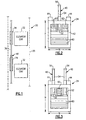
Figure 1 schematically illustrates selected portions of an elevator system including a counterweight having a buffer supported for movement with the counterweight. -
Figure 2 schematically shows one example counterweight embodiment. -
Figure 3 shows another example counterweight embodiment. -
Figure 1 schematically shows selected portions of anelevator system 20. Afirst elevator car 22 is coupled with a first counterweight for movement within ahoistway 26. Although not shown inFigure 1 , thefirst elevator car 22 is coupled to thefirst counterweight 24 by a plurality of ropes or belts as known. Asecond elevator car 32 is positioned below (according to the drawing) thefirst elevator car 22. Thesecond elevator car 32 is associated with asecond counterweight 34 by a load bearing member (not shown) so that both move within thehoistway 26 as known. - In this example, the
counterweights common guide rails 36. In other words, thecounterweights same guide rails 36. - Another feature of the
example system 20 schematically shown inFigure 1 is that at least onebuffer member 40 is supported on at least one of thecounterweights -
Figure 2 schematically shows one example embodiment of acounterweight 24 having abuffer member 40 that is supported by the counterweight for movement with the counterweight within thehoistway 26. In this example, thecounterweight 24 has astructure 42 that defines an outer boundary of the counterweight. In this example, thestructure 42 comprises a frame that is made in a generally known manner. The outer boundary defined by thestructure 42 includes a height dimension H and a width dimension W. - The illustrated example includes
guide supports 44 that are outside of the outer boundary in this example. Of course, the guide supports 44 may be within the outer boundary, depending on the configuration of the counterweight structure. The guide supports operate in a known manner to facilitate moving the counterweight along theguide rails 36. - In the example of
Figure 2 , thebuffer member 40 has afirst portion 52 that is within the outer boundary of thecounterweight structure 42. Asecond portion 54 is beyond the outer boundary. In this example, adistal end 56 of thebuffer member 40 is adapted to contact the other counterweight (i.e., the counterweight 34) before the counterweight structures would contact each other. In this example, thebuffer member 40 has cooperating cylinders that operate in a known manner (i.e., hydraulic) to provide an energy absorbing function in the event that the counterweights move close enough to contact each other. - In the example of
Figure 2 , theframe 42 supports a plurality offillers 60. In one example, the fillers comprise plates as known. Thefillers 60 have a lateral dimension that corresponds to the width W of thestructure 42. The term "lateral" as used in this description refers to a direction taken in the width W direction as shown in the drawings. Of course, the size of the frame members and the size of thefillers 60 fit within the outer boundary of thecounterweight 24. - The example of
Figure 2 also includes a plurality ofsecond filler members 62 that have a second, smaller lateral dimension. In this example, two sets ofsecond filler members 62 are provided, one on either lateral side of thefirst portion 52 of thebuffer member 40. Accordingly, thefiller members 62 have a dimension that corresponds to a difference between the width of thestructure 42 and a width of thefirst portion 52 of thebuffer member 40. -
Figure 3 shows another example including twobuffer members 40. One difference between the examples ofFigure 2 and Figure 3 is that the latter includes one set ofsecond fillers 62 positioned between thebuffer members 40. - In either of the examples of
Figure 2 and Figure 3 , the smaller,second fillers 62 provide for establishing a desired counterweight mass without increasing the height of the counterweight. In other words, the space within the outer boundary occupied by thefirst portion 52 of thebuffer member 40 in the height direction may also be occupied by smaller fillers. - Although plate-style fillers are illustrated, other fillers are possible such as concrete and other known items.
- Although the
buffer member 40 is shown on thecounterweight 24 in the illustrated example, it could also be provided on thecounterweight 34 so long as the buffer faces thefirst counterweight 24 in thehoistway 26. Additionally, both counterweights may include at least one buffer member. The arrangements and placement of the buffer member or members will depend, in part, on a selected roping arrangement. Those skilled in the art who have the benefit of this description will be able to select an appropriate arrangement to meet their particular needs. - The preceding description is exemplary rather than limiting in nature. Variations and modifications to the disclosed examples may become apparent to those skilled in the art that do not necessarily depart from this invention. The scope of legal protection given to this invention can only be determined by studying the following claims.
Claims (9)
- A counterweight (24) for use in an elevator system, comprising:a structure (42) that defines an outer boundary of the counterweight (24); anda buffer member (40) that is supported for movement with the structure (42) characterised in that:the buffer member (40) is supported such that a first portion (52) of the buffer member (40) is within the outer boundary and is in a fixed position relative to the structure;the buffer member (40) has a second portion (54) beyond the outer boundary, the second portion (54) being moveable relative to the first portion (52) such that a distance between the outer boundary and a distal end of the second portion (54) is variable;the structure comprises a frame (42) and includes a plurality of fillers (60,62) supported by the frame (42); andat least a first one of the fillers (60) has a first dimension corresponding to a width dimension of the frame (42) and at least a second one of the fillers (62) has a second, smaller dimension corresponding to a difference between the width dimension of the frame (42) and a width dimension of the first portion (52) of the buffer member (40).
- The counterweight of claim 1, wherein the second filler (62) is positioned laterally on a side of the first portion (52).
- The counterweight of claim 2, including second fillers (62) on opposite sides of the first portion (52), respectively.
- The counterweight of claim 1, including a plurality of the buffer members (40) and wherein the second filler (62) is positioned between the first portions (52) of the buffer members (40).
- The counterweight of claim 1, including a plurality of the first fillers (60) and a plurality of the second fillers (62).
- The counterweight of claim 1, wherein the fillers (60,62) comprise plates.
- An elevator system comprising:a first elevator car (22) in a hoistway (26);a first counterweight (24) in the hoistway (26);a first load bearing member coupling the first elevator car (22) to the first counterweight (24);a second elevator car (32) in the hoistway (26) below the first elevator car (22);a second counterweight (34) in the hoistway above the first counterweight (22);a second load bearing member coupling the second elevator car (32) to the second counterweight (34); andone of the first or second counterweights (24,34) being a counterweight as claimed in any preceding claim.
- The system of claim 7, wherein the second portion (54) of the buffer member (40) is beyond the outer boundary of the corresponding counterweight (32,34) in a direction toward the other counterweight (34,32) such that the second portion (54) contacts the other counterweight (34,32) before the counterweights (32,34) contact each other.
- The system of claim 8, wherein the second portion (54) prevents the other counterweight (34,32) from contacting the structure of the associated counterweight (32,34).
Applications Claiming Priority (1)
| Application Number | Priority Date | Filing Date | Title |
|---|---|---|---|
| PCT/US2005/036654 WO2007046784A1 (en) | 2005-10-12 | 2005-10-12 | Counterweight with partially imbedded buffer |
Publications (3)
| Publication Number | Publication Date |
|---|---|
| EP1934126A1 EP1934126A1 (en) | 2008-06-25 |
| EP1934126A4 EP1934126A4 (en) | 2011-06-08 |
| EP1934126B1 true EP1934126B1 (en) | 2012-11-28 |
Family
ID=37962784
Family Applications (1)
| Application Number | Title | Priority Date | Filing Date |
|---|---|---|---|
| EP05807666A Expired - Lifetime EP1934126B1 (en) | 2005-10-12 | 2005-10-12 | Counterweight with partially imbedded buffer |
Country Status (6)
| Country | Link |
|---|---|
| US (1) | US20080257654A1 (en) |
| EP (1) | EP1934126B1 (en) |
| JP (1) | JP2009511391A (en) |
| CN (1) | CN101287668A (en) |
| RU (1) | RU2481262C2 (en) |
| WO (1) | WO2007046784A1 (en) |
Families Citing this family (3)
| Publication number | Priority date | Publication date | Assignee | Title |
|---|---|---|---|---|
| WO2016118443A1 (en) * | 2015-01-21 | 2016-07-28 | Otis Elevator Company | Buffering device for multiple-car elevator system |
| EP3199483A1 (en) * | 2016-01-28 | 2017-08-02 | Kone Corporation | Elevator counterweight |
| CN112897299B (en) * | 2021-01-14 | 2022-10-28 | 迅达(中国)电梯有限公司 | Counterweight buffer mechanism, counterweight device and elevator system |
Family Cites Families (21)
| Publication number | Priority date | Publication date | Assignee | Title |
|---|---|---|---|---|
| US1896776A (en) * | 1928-02-17 | 1933-02-07 | Westinghouse Electric & Mfg Co | Multiple elevator system |
| US2417947A (en) * | 1943-12-06 | 1947-03-25 | Mary B Reedy | Hydraulically operated elevator |
| US2537075A (en) * | 1948-10-09 | 1951-01-09 | Otis Elevator Co | Compensating apparatus for elevator hoisting roping |
| US3740782A (en) * | 1971-12-23 | 1973-06-26 | Sverdrup & Parcel Ass Inc | Method and apparatus for servicing counterbalanced lifting device |
| JPS59153773A (en) * | 1983-02-04 | 1984-09-01 | 株式会社東芝 | Elevator |
| JP2596610B2 (en) * | 1989-02-28 | 1997-04-02 | オーチス エレベータ カンパニー | Column vibration detector for elevator system driven by linear motor |
| JPH02241353A (en) * | 1989-02-28 | 1990-09-26 | Otis Elevator Co | Air gap adjuster for cylindrical linear motor |
| US5080201A (en) * | 1990-04-02 | 1992-01-14 | Otis Elevator Company | Diversion of airflow around an elevator counterweight |
| RU1781156C (en) * | 1991-01-11 | 1992-12-15 | Научно-Производственное Объединение По Выпуску Лифтов "Лифтмаш" | Hydraulic lift |
| US5090516A (en) * | 1991-03-15 | 1992-02-25 | Otis Elevator Company | Elevator linear motor bus bar |
| JPH0537847U (en) * | 1991-03-25 | 1993-05-21 | オーチス エレベータ カンパニー | Linear motor elevator |
| FI93631C (en) * | 1993-01-11 | 1995-05-10 | Kone Oy | Counterbalanced lift motor |
| US5419414A (en) * | 1993-11-18 | 1995-05-30 | Sakita; Masami | Elevator system with multiple cars in the same hoistway |
| JP3420811B2 (en) * | 1993-12-17 | 2003-06-30 | オーチス エレベータ カンパニー | Linear motor type elevator |
| JP2001163543A (en) * | 1999-12-08 | 2001-06-19 | Oil Drive Kogyo Kk | Method of installing shock absorber for elevator |
| EP1311146A3 (en) * | 2001-11-07 | 2005-11-23 | Alcatel | Electrical shield |
| JP2003252546A (en) * | 2002-03-01 | 2003-09-10 | Mitsubishi Electric Corp | Elevator shock absorber |
| JP4107863B2 (en) * | 2002-03-27 | 2008-06-25 | 東芝エレベータ株式会社 | Elevator equipment |
| JP4113760B2 (en) * | 2002-11-01 | 2008-07-09 | 三菱電機株式会社 | Elevator equipment |
| ATE556019T1 (en) * | 2004-12-03 | 2012-05-15 | Otis Elevator Co | ELEVATOR COUNTERWEIGHT WITH BUFFER |
| CN1976856A (en) * | 2005-05-16 | 2007-06-06 | 三菱电机株式会社 | Elevator device |
-
2005
- 2005-10-12 RU RU2008118423/11A patent/RU2481262C2/en not_active IP Right Cessation
- 2005-10-12 JP JP2008535501A patent/JP2009511391A/en active Pending
- 2005-10-12 US US12/089,454 patent/US20080257654A1/en not_active Abandoned
- 2005-10-12 CN CNA2005800518217A patent/CN101287668A/en active Pending
- 2005-10-12 WO PCT/US2005/036654 patent/WO2007046784A1/en not_active Ceased
- 2005-10-12 EP EP05807666A patent/EP1934126B1/en not_active Expired - Lifetime
Also Published As
| Publication number | Publication date |
|---|---|
| CN101287668A (en) | 2008-10-15 |
| WO2007046784A1 (en) | 2007-04-26 |
| JP2009511391A (en) | 2009-03-19 |
| US20080257654A1 (en) | 2008-10-23 |
| RU2008118423A (en) | 2009-11-27 |
| EP1934126A1 (en) | 2008-06-25 |
| EP1934126A4 (en) | 2011-06-08 |
| RU2481262C2 (en) | 2013-05-10 |
Similar Documents
| Publication | Publication Date | Title |
|---|---|---|
| EP1831093B1 (en) | Elevator system with multiple cars in a hoistway | |
| JP4890572B2 (en) | Elevator system | |
| JP2012525309A (en) | Elevator system with multiple cars in a single hoistway | |
| CN1572701A (en) | Elevator installation with a buffer for creating a zone of protection in an elevator installation and a method of creating a zone of protection | |
| CN110116954B (en) | Double-deck elevator system | |
| US20080257654A1 (en) | Counterweight With Partially Imbedded Buffer | |
| CN113242837A (en) | Elevator installation with derailing protection | |
| EP3514097B1 (en) | H frame for a double deck elevator | |
| EP1928776B1 (en) | Frangible buffer for an elevator system with multiple cars in a hoistway | |
| KR20080056290A (en) | Counterweight with partially embedded buffer | |
| HK1125089A (en) | Counterweight with partially imbedded buffer | |
| CN101643167B (en) | Elevator system provided with a plurality of cages in hoistway | |
| JP3175754U (en) | Counterweight with partially embedded shock absorber | |
| HK1117126B (en) | Elevator system with multiple cars in a hoistway | |
| CN101272979A (en) | Vulnerable buffers for elevator systems with multiple cars in the elevator shaft | |
| HK1139371B (en) | Elevator system with multiple cars in hoistway | |
| HK1172310A (en) | Elevator system with multiple elevator cars in a hoistway | |
| HK1124821A (en) | Frangible buffer for an elevator system with multiple cars in a hoistway | |
| KR20080055962A (en) | Elevator system fusible buffer with multiple cars in hoistway |
Legal Events
| Date | Code | Title | Description |
|---|---|---|---|
| PUAI | Public reference made under article 153(3) epc to a published international application that has entered the european phase |
Free format text: ORIGINAL CODE: 0009012 |
|
| 17P | Request for examination filed |
Effective date: 20080328 |
|
| AK | Designated contracting states |
Kind code of ref document: A1 Designated state(s): AT BE BG CH CY CZ DE DK EE ES FI FR GB GR HU IE IS IT LI LT LU LV MC NL PL PT RO SE SI SK TR |
|
| A4 | Supplementary search report drawn up and despatched |
Effective date: 20110511 |
|
| REG | Reference to a national code |
Ref country code: DE Ref legal event code: R079 Ref document number: 602005037218 Country of ref document: DE Free format text: PREVIOUS MAIN CLASS: B66B0005000000 Ipc: B66B0017120000 |
|
| RIC1 | Information provided on ipc code assigned before grant |
Ipc: B66B 5/28 20060101ALI20111212BHEP Ipc: B66B 17/12 20060101AFI20111212BHEP |
|
| GRAP | Despatch of communication of intention to grant a patent |
Free format text: ORIGINAL CODE: EPIDOSNIGR1 |
|
| DAX | Request for extension of the european patent (deleted) | ||
| RAP1 | Party data changed (applicant data changed or rights of an application transferred) |
Owner name: OTIS ELEVATOR COMPANY |
|
| GRAS | Grant fee paid |
Free format text: ORIGINAL CODE: EPIDOSNIGR3 |
|
| GRAA | (expected) grant |
Free format text: ORIGINAL CODE: 0009210 |
|
| AK | Designated contracting states |
Kind code of ref document: B1 Designated state(s): AT BE BG CH CY CZ DE DK EE ES FI FR GB GR HU IE IS IT LI LT LU LV MC NL PL PT RO SE SI SK TR |
|
| REG | Reference to a national code |
Ref country code: GB Ref legal event code: FG4D |
|
| REG | Reference to a national code |
Ref country code: CH Ref legal event code: EP |
|
| REG | Reference to a national code |
Ref country code: AT Ref legal event code: REF Ref document number: 586048 Country of ref document: AT Kind code of ref document: T Effective date: 20121215 |
|
| REG | Reference to a national code |
Ref country code: IE Ref legal event code: FG4D |
|
| REG | Reference to a national code |
Ref country code: DE Ref legal event code: R096 Ref document number: 602005037218 Country of ref document: DE Effective date: 20130117 |
|
| REG | Reference to a national code |
Ref country code: AT Ref legal event code: MK05 Ref document number: 586048 Country of ref document: AT Kind code of ref document: T Effective date: 20121128 |
|
| REG | Reference to a national code |
Ref country code: NL Ref legal event code: VDEP Effective date: 20121128 |
|
| REG | Reference to a national code |
Ref country code: LT Ref legal event code: MG4D |
|
| PG25 | Lapsed in a contracting state [announced via postgrant information from national office to epo] |
Ref country code: FI Free format text: LAPSE BECAUSE OF FAILURE TO SUBMIT A TRANSLATION OF THE DESCRIPTION OR TO PAY THE FEE WITHIN THE PRESCRIBED TIME-LIMIT Effective date: 20121128 Ref country code: SE Free format text: LAPSE BECAUSE OF FAILURE TO SUBMIT A TRANSLATION OF THE DESCRIPTION OR TO PAY THE FEE WITHIN THE PRESCRIBED TIME-LIMIT Effective date: 20121128 Ref country code: ES Free format text: LAPSE BECAUSE OF FAILURE TO SUBMIT A TRANSLATION OF THE DESCRIPTION OR TO PAY THE FEE WITHIN THE PRESCRIBED TIME-LIMIT Effective date: 20130311 Ref country code: LT Free format text: LAPSE BECAUSE OF FAILURE TO SUBMIT A TRANSLATION OF THE DESCRIPTION OR TO PAY THE FEE WITHIN THE PRESCRIBED TIME-LIMIT Effective date: 20121128 |
|
| PG25 | Lapsed in a contracting state [announced via postgrant information from national office to epo] |
Ref country code: PT Free format text: LAPSE BECAUSE OF FAILURE TO SUBMIT A TRANSLATION OF THE DESCRIPTION OR TO PAY THE FEE WITHIN THE PRESCRIBED TIME-LIMIT Effective date: 20130328 Ref country code: CY Free format text: LAPSE BECAUSE OF FAILURE TO SUBMIT A TRANSLATION OF THE DESCRIPTION OR TO PAY THE FEE WITHIN THE PRESCRIBED TIME-LIMIT Effective date: 20121128 Ref country code: SI Free format text: LAPSE BECAUSE OF FAILURE TO SUBMIT A TRANSLATION OF THE DESCRIPTION OR TO PAY THE FEE WITHIN THE PRESCRIBED TIME-LIMIT Effective date: 20121128 Ref country code: GR Free format text: LAPSE BECAUSE OF FAILURE TO SUBMIT A TRANSLATION OF THE DESCRIPTION OR TO PAY THE FEE WITHIN THE PRESCRIBED TIME-LIMIT Effective date: 20130301 Ref country code: BE Free format text: LAPSE BECAUSE OF FAILURE TO SUBMIT A TRANSLATION OF THE DESCRIPTION OR TO PAY THE FEE WITHIN THE PRESCRIBED TIME-LIMIT Effective date: 20121128 Ref country code: LV Free format text: LAPSE BECAUSE OF FAILURE TO SUBMIT A TRANSLATION OF THE DESCRIPTION OR TO PAY THE FEE WITHIN THE PRESCRIBED TIME-LIMIT Effective date: 20121128 Ref country code: PL Free format text: LAPSE BECAUSE OF FAILURE TO SUBMIT A TRANSLATION OF THE DESCRIPTION OR TO PAY THE FEE WITHIN THE PRESCRIBED TIME-LIMIT Effective date: 20121128 |
|
| PG25 | Lapsed in a contracting state [announced via postgrant information from national office to epo] |
Ref country code: AT Free format text: LAPSE BECAUSE OF FAILURE TO SUBMIT A TRANSLATION OF THE DESCRIPTION OR TO PAY THE FEE WITHIN THE PRESCRIBED TIME-LIMIT Effective date: 20121128 |
|
| PG25 | Lapsed in a contracting state [announced via postgrant information from national office to epo] |
Ref country code: DK Free format text: LAPSE BECAUSE OF FAILURE TO SUBMIT A TRANSLATION OF THE DESCRIPTION OR TO PAY THE FEE WITHIN THE PRESCRIBED TIME-LIMIT Effective date: 20121128 Ref country code: BG Free format text: LAPSE BECAUSE OF FAILURE TO SUBMIT A TRANSLATION OF THE DESCRIPTION OR TO PAY THE FEE WITHIN THE PRESCRIBED TIME-LIMIT Effective date: 20130228 Ref country code: CZ Free format text: LAPSE BECAUSE OF FAILURE TO SUBMIT A TRANSLATION OF THE DESCRIPTION OR TO PAY THE FEE WITHIN THE PRESCRIBED TIME-LIMIT Effective date: 20121128 Ref country code: EE Free format text: LAPSE BECAUSE OF FAILURE TO SUBMIT A TRANSLATION OF THE DESCRIPTION OR TO PAY THE FEE WITHIN THE PRESCRIBED TIME-LIMIT Effective date: 20121128 Ref country code: SK Free format text: LAPSE BECAUSE OF FAILURE TO SUBMIT A TRANSLATION OF THE DESCRIPTION OR TO PAY THE FEE WITHIN THE PRESCRIBED TIME-LIMIT Effective date: 20121128 |
|
| PG25 | Lapsed in a contracting state [announced via postgrant information from national office to epo] |
Ref country code: RO Free format text: LAPSE BECAUSE OF FAILURE TO SUBMIT A TRANSLATION OF THE DESCRIPTION OR TO PAY THE FEE WITHIN THE PRESCRIBED TIME-LIMIT Effective date: 20121128 Ref country code: NL Free format text: LAPSE BECAUSE OF FAILURE TO SUBMIT A TRANSLATION OF THE DESCRIPTION OR TO PAY THE FEE WITHIN THE PRESCRIBED TIME-LIMIT Effective date: 20121128 Ref country code: IT Free format text: LAPSE BECAUSE OF FAILURE TO SUBMIT A TRANSLATION OF THE DESCRIPTION OR TO PAY THE FEE WITHIN THE PRESCRIBED TIME-LIMIT Effective date: 20121128 |
|
| PLBE | No opposition filed within time limit |
Free format text: ORIGINAL CODE: 0009261 |
|
| STAA | Information on the status of an ep patent application or granted ep patent |
Free format text: STATUS: NO OPPOSITION FILED WITHIN TIME LIMIT |
|
| 26N | No opposition filed |
Effective date: 20130829 |
|
| REG | Reference to a national code |
Ref country code: DE Ref legal event code: R097 Ref document number: 602005037218 Country of ref document: DE Effective date: 20130829 |
|
| PG25 | Lapsed in a contracting state [announced via postgrant information from national office to epo] |
Ref country code: MC Free format text: LAPSE BECAUSE OF FAILURE TO SUBMIT A TRANSLATION OF THE DESCRIPTION OR TO PAY THE FEE WITHIN THE PRESCRIBED TIME-LIMIT Effective date: 20121128 |
|
| REG | Reference to a national code |
Ref country code: CH Ref legal event code: PL |
|
| REG | Reference to a national code |
Ref country code: DE Ref legal event code: R119 Ref document number: 602005037218 Country of ref document: DE Effective date: 20140501 |
|
| REG | Reference to a national code |
Ref country code: IE Ref legal event code: MM4A |
|
| PG25 | Lapsed in a contracting state [announced via postgrant information from national office to epo] |
Ref country code: CH Free format text: LAPSE BECAUSE OF NON-PAYMENT OF DUE FEES Effective date: 20131031 Ref country code: LI Free format text: LAPSE BECAUSE OF NON-PAYMENT OF DUE FEES Effective date: 20131031 |
|
| REG | Reference to a national code |
Ref country code: FR Ref legal event code: ST Effective date: 20140630 |
|
| PG25 | Lapsed in a contracting state [announced via postgrant information from national office to epo] |
Ref country code: DE Free format text: LAPSE BECAUSE OF NON-PAYMENT OF DUE FEES Effective date: 20140501 Ref country code: FR Free format text: LAPSE BECAUSE OF NON-PAYMENT OF DUE FEES Effective date: 20131031 |
|
| PG25 | Lapsed in a contracting state [announced via postgrant information from national office to epo] |
Ref country code: IE Free format text: LAPSE BECAUSE OF NON-PAYMENT OF DUE FEES Effective date: 20131012 |
|
| PGFP | Annual fee paid to national office [announced via postgrant information from national office to epo] |
Ref country code: GB Payment date: 20141008 Year of fee payment: 10 |
|
| PG25 | Lapsed in a contracting state [announced via postgrant information from national office to epo] |
Ref country code: TR Free format text: LAPSE BECAUSE OF FAILURE TO SUBMIT A TRANSLATION OF THE DESCRIPTION OR TO PAY THE FEE WITHIN THE PRESCRIBED TIME-LIMIT Effective date: 20121128 |
|
| PG25 | Lapsed in a contracting state [announced via postgrant information from national office to epo] |
Ref country code: HU Free format text: LAPSE BECAUSE OF FAILURE TO SUBMIT A TRANSLATION OF THE DESCRIPTION OR TO PAY THE FEE WITHIN THE PRESCRIBED TIME-LIMIT; INVALID AB INITIO Effective date: 20051012 Ref country code: LU Free format text: LAPSE BECAUSE OF NON-PAYMENT OF DUE FEES Effective date: 20131012 |
|
| GBPC | Gb: european patent ceased through non-payment of renewal fee |
Effective date: 20151012 |
|
| PG25 | Lapsed in a contracting state [announced via postgrant information from national office to epo] |
Ref country code: IS Free format text: LAPSE BECAUSE OF FAILURE TO SUBMIT A TRANSLATION OF THE DESCRIPTION OR TO PAY THE FEE WITHIN THE PRESCRIBED TIME-LIMIT Effective date: 20121128 |
|
| PG25 | Lapsed in a contracting state [announced via postgrant information from national office to epo] |
Ref country code: GB Free format text: LAPSE BECAUSE OF NON-PAYMENT OF DUE FEES Effective date: 20151012 |