EP1933435B1 - Zur Unterstützung eines oder mehrerer Elektrogeräte konfigurierte Kabelverwaltungsvorrichtung sowie Herstellungs- und Verwendungsverfahren dafür - Google Patents
Zur Unterstützung eines oder mehrerer Elektrogeräte konfigurierte Kabelverwaltungsvorrichtung sowie Herstellungs- und Verwendungsverfahren dafür Download PDFInfo
- Publication number
- EP1933435B1 EP1933435B1 EP07253929A EP07253929A EP1933435B1 EP 1933435 B1 EP1933435 B1 EP 1933435B1 EP 07253929 A EP07253929 A EP 07253929A EP 07253929 A EP07253929 A EP 07253929A EP 1933435 B1 EP1933435 B1 EP 1933435B1
- Authority
- EP
- European Patent Office
- Prior art keywords
- cover
- management device
- cable management
- housing
- wall
- Prior art date
- Legal status (The legal status is an assumption and is not a legal conclusion. Google has not performed a legal analysis and makes no representation as to the accuracy of the status listed.)
- Not-in-force
Links
Images


Classifications
-
- H—ELECTRICITY
- H02—GENERATION; CONVERSION OR DISTRIBUTION OF ELECTRIC POWER
- H02G—INSTALLATION OF ELECTRIC CABLES OR LINES, OR OF COMBINED OPTICAL AND ELECTRIC CABLES OR LINES
- H02G3/00—Installations of electric cables or lines or protective tubing therefor in or on buildings, equivalent structures or vehicles
- H02G3/02—Details
- H02G3/04—Protective tubing or conduits, e.g. cable ladders or cable troughs
- H02G3/0437—Channels
-
- H—ELECTRICITY
- H02—GENERATION; CONVERSION OR DISTRIBUTION OF ELECTRIC POWER
- H02J—CIRCUIT ARRANGEMENTS OR SYSTEMS FOR SUPPLYING OR DISTRIBUTING ELECTRIC POWER; SYSTEMS FOR STORING ELECTRIC ENERGY
- H02J7/00—Circuit arrangements for charging or depolarising batteries or for supplying loads from batteries
- H02J7/34—Parallel operation in networks using both storage and other DC sources, e.g. providing buffering
- H02J7/35—Parallel operation in networks using both storage and other DC sources, e.g. providing buffering with light sensitive cells
-
- H02J7/731—
-
- H—ELECTRICITY
- H05—ELECTRIC TECHNIQUES NOT OTHERWISE PROVIDED FOR
- H05K—PRINTED CIRCUITS; CASINGS OR CONSTRUCTIONAL DETAILS OF ELECTRIC APPARATUS; MANUFACTURE OF ASSEMBLAGES OF ELECTRICAL COMPONENTS
- H05K5/00—Casings, cabinets or drawers for electric apparatus
- H05K5/02—Details
- H05K5/0247—Electrical details of casings, e.g. terminals, passages for cables or wiring
-
- H—ELECTRICITY
- H02—GENERATION; CONVERSION OR DISTRIBUTION OF ELECTRIC POWER
- H02J—CIRCUIT ARRANGEMENTS OR SYSTEMS FOR SUPPLYING OR DISTRIBUTING ELECTRIC POWER; SYSTEMS FOR STORING ELECTRIC ENERGY
- H02J7/00—Circuit arrangements for charging or depolarising batteries or for supplying loads from batteries
- H02J7/34—Parallel operation in networks using both storage and other DC sources, e.g. providing buffering
- H02J7/342—The other DC source being a battery actively interacting with the first one, i.e. battery to battery charging
Definitions
- This invention relates generally to cable management devices, and relates more particularly to cable management devices that provide support for one or more electrical device and methods of manufacturing and using the same.
- the accessory comprises a support body defining compartments within which mobile telephones and mobile telephone chargers can be held.
- the compartments for holding telephone chargers are each associated with a socket arrangement that can receive the contact pins of a telephone charger, all the socket arrangements being electrically connected with one another and being connectable to an electricity power supply.
- the accessory permits a plurality of mobile telephone s to be simultaneously held therein and to be charged via their chargers from a single electricity power supply.
- Couple should be broadly understood and refer to connecting two or more elements or signals, electrically and/or mechanically, either directly or indirectly through intervening circuitry and/or elements.
- Two or more electrical elements may be electrically coupled, either direct or indirectly, but not be mechanically coupled;
- two or more mechanical elements may be mechanically coupled, either direct or indirectly, but not be electrically coupled;
- two or more electrical elements may be mechanically coupled, directly or indirectly, but not be electrically coupled.
- Coupling (whether only mechanical, only electrical, or both) may be for any length of time. e.g., permanent or semi-permanent or only for an instant.
- Electrode coupling and the like should be broadly understood and include coupling involving any electrical signal, whether a power signal, a data signal, and/or other types or combinations of electrical signals.
- Mechanical coupling and the like should be broadly understood and include mechanical coupling of all types.
- a cable management device is configured to support one or more electrical devices.
- the cable management device can include: (a) a housing defining an interior space and having one or more apertures extending from an exterior of the housing to the interior space; and (b) one or more electrical outlets located in the interior space of the housing.
- the housing can include: (a) a stationary portion with a support mechanism; and (b) a cover hingedly attached to the stationary portion.
- the support mechanism can support the one or more electrical devices.
- the cover can be configured to move between a first position, in which the cover substantially encloses the interior space, and a second position, in which the interior space is exposed.
- the one or more apertures can provide access to the interior space from the exterior of the housing when the cover is in the first position.
- the housing can be configured such that the cover can be moved between the first position and the second position while the support mechanism maintains support of the one or more electrical devices
- the holder can include: (a) a receptacle defining a cavity, the receptacle including: (1) a first wall with an external surface; (2) a second wall; (3) an L-shaped component; and (4) a hinge; and (b) one or more electrical outlets located in the cavity of the receptacle.
- the first wall can be configured to hold the at least one electrical device at the external surface.
- the hinge can couple the L-shaped component to the second wall such that the L-shaped component and the one or more electrical outlets can be pivoted in relation to the second wall.
- the L-shaped component can be pivoted in relation to the second wall such that the receptacle can be placed in a closed arrangement and an open arrangement.
- a method of providing a cable management device includes: (a) providing a receptacle with one or more apertures, where providing the receptacle includes: (1) providing a stationary portion configured to support one or more electrical devices; (2) providing a cover; and (3) hingedly attaching the cover to the stationary portion such that the stationary portion can support the one or more electrical devices when the cover is in an open position, and where the cover and the stationary portion define an interior space; and (b) positioning one or more electrical outlets in the interior space such that the one or more electrical outlets can be accessed through the one or more apertures when the cover is in a closed position.
- a method of providing a holder includes: (a) providing a receptacle including; (1) a first wall configured to hold at least one electrical device at an external surface; and (2) a second wall spaced apart from the first wall; (b) providing an L-shaped component with one or more electrical outlets; and (c) attaching the L-shaped component to the second wall such that the L-shaped component and the one or more electrical outlets can be pivoted in relation to the second wall.
- a method of using a holder includes: (a) using the holder to support an electrical device while the electrical device is being electrically charged; and (b) opening a cover of the holder while the holder continues to support the electrical device and while the electrical device continues to electrically charge.
- FIG. 1 illustrates a top, side, front isometric view of a cable management device 100 in an open configuration and supporting an electrical device 150, according to a first embodiment.
- FIG. 2 illustrates a top, side isometric view of cable management device 100 in a closed configuration and supporting electrical device 150. according to the first embodiment.
- FIG. 3 illustrates a top, front isometric view of cable management device 100 in the closed configuration, according to the first embodiment.
- Cable management device 100 is merely exemplary and is not limited to the embodiments presented herein. Cable management device 100 can be employed in many different embodiments or examples not specifically depicted or described herein.
- a holder or cable management device 100 for at least one electrical device 150 can include: (a) a receptacle or housing 101 defining a cavity or interior space 102 and having one or more apertures 103 extending from an exterior 104 of housing 101 to interior space 102; (b) one or more electrical outlets 106; and (c) a electrical connector 160 to receive electrical power from an external source and supply the electrical power to electrical outlets 106.
- Cable management device 100 can be configured to support electrical device 150.
- Electrical device 150 can be coupled to at least one cable 107.
- Cable 107 can have a plug 108 and a connector 151 configured to removably couple electrical device 150, Plug 108 can be removably coupled to one of electrical outlets 106.
- plug 108 can be a transformer block.
- electrical device 150 can be an electrical device or accessory such as a mobile phone, a personal digital assistant (PDA), a digital music (MP3) player, or the like.
- Electrical device 150 can be stored and displayed on housing 101 while the electrical device 150 is electrically charged as shown in FIGS. 1 and 2 .
- plug 108 and a portion of cable 107 can be stored in interior space 102.
- more than one electrical device can be stored and displayed on housing 101 and more than one cable and plug can be stored in interior space 102.
- housing 101 can include: (a) a stationary portion 11a with a support mechanism 111 configured to support electrical device 150; (b) a cover 120 coupled to stationary portion 110; and (c) a hinge 130 coupling cover 120 to stationary portion 110.
- cover 120 is coupled to stationary portion 110 by hinge 130 at a junction 131.
- Hinge 130 couples cover 120 to stationary portion 110 such that cover 120 and electrical outlets 106 can be pivoted in relation to stationary portion 110. That is, cover 120 is configured to move between a closed configuration ( FIGs. 2 and 3 ), in which housing 101 substantially encloses interior space 102, and an open configuration ( FIG. 1 ), in which interior space 102 is exposed. Housing 101 is configured such that cover 120 can be moved between the open configuration and the closed configuration, while support mechanism 111 maintains support for electrical device 150. When housing 101 is in the closed position, cable management device 100 hides plug 108 and a portion of cable 107.
- Hinge 130 can be accomplished in any of a variety of ways, including, for example, by using a metal or plastic hinge attached to stationary portion 110, a living hinge molded into the material of housing 101, or a slot and pin arrangement.
- stationary portion 110 includes: (a) a wall 112 with an external surface 117; (b) a wall 113 adjacent to wall 112; (c) a wall 314 ( FIG. 3 ) adjacent to wall 112 and spaced apart and/or opposite wall 113; (d) a wall 115 adjacent to walls 112, 113, and 314; (e) a wall 116 adjacent to walls 113, 314, and 115 and spaced apart and/or opposite wall 112.
- walls 112, 113, 314, 115, and/or 116 can form a part of exterior 104.
- Cover 120 can be hingedly attached to at least one of walls 113, 314, and 116.
- stationary portion 110 can have other shapes or numbers of walls.
- stationary portion could include one wall having a dome shape and a second wall forming a floor of the stationary portion.
- stationary portion 110 could have a first wall with support mechanism 111 and a second wall spaced apart from the first wall. The first and second wall could be coupled using many designs not illustrated herein.
- wall 112 is configured to hold electrical device 150 at external surface 117. Electrical device 150 can remain on wall 112 while a user moves cable management device 100 between the open and closed configurations to remove, add, or adjust cable 107.
- wall 112 can be at an angle with respect to wall 116. In some examples, the angle is between approximately zero and sixty degrees. In one embodiment, the angle is approximately twenty degrees.
- Support mechanism 111 can be located at external surface 117 and configured to hold electrical device 150 to external surface 117.
- support mechanism 111 can include at least one of: (a) one or more ridges; and (b) one or more grooves,
- electrical device 150 can be placed in grooves or slots at external surface 117 to hold electrical device 150 in place.
- support mechanism 111 can include a ridge at external surface 117 to support electrical device 150.
- external surface 117 could be designed to have a high-friction surface. The high-friction surface could be support mechanism 111.
- a high-friction surface could be defined as a surface with suitable friction to hold at least one of a mobile phone, a PDA, or an MP3 player stationary on external surface 117.
- support mechanism 111 could be a patterned or roughened external surface 117.
- cover 120 can include: (a) a wall or section 121 forming a portion of exterior 104; and (b) a wall or section 122 located in interior space 102 when housing 101 is in the closed configuration.
- section 121 and section 122 can be coupled to form an L-shaped component.
- a height of section 121 can be less than a height of section 122.
- section 121 is coupled to section 122 at a junction point (e.g., junction 131) and cover 120 is coupled to hinge 130 at the same junction point.
- section 121 is coupled to section 122 at junction 131 such that section 121 is substantially perpendicular to section 122.
- substantially perpendicular means ninety degrees plus or minus three degrees. In another embodiment, substantially perpendicular means an angle between eighty degrees and a hundred and ten degrees.
- an "L-shaped" means that a first section (e.g., section 121) is substantially perpendicular to a second section (e.g., section 122). In yet other embodiments, "L-shaped” means that the first section is at non-zero (or non-one hundred and eight) degree angle with respect second section.
- Section 121 can have an external surface 323 ( FIG. 3 ) at exterior 104 and an interior surface 125 opposite external surface 323.
- electrical outlets 1.06 are located at interior surface 125. Electrical outlets 106 can be in interior space 102 when cover 120 is in the closed configuration.
- section 121 can include: (a) an end 326 coupled to hinge 130; and (b) an end 327 opposite end 326.
- end 326 is hingedly attached to stationary portion 110.
- Housing 101 is configured such that an aperture or gap 305 exists between end 327 and stationary portion 110 when cover 120 is in the closed configuration. Gap 305 provides access to interior space 102 when housing 101 is in the closed configuration. Furthermore, gap 305 allows cable 107 to pass between interior space 102 and exterior 104 when cover 120 is in the closed configuration.
- housing 101 can include one or more apertures 103 in addition to or in place of gap 305.
- Apertures 103 can provide access to interior space 102 from exterior 104 when cover 120 is in the closed configuration.
- Housing 101 can be configured such that each of apertures 103 provide access to electrical outlets 106 and allow cable 107 to enter interior space 102 when cover 120 is in the closed configuration.
- apertures 103 are located in stationary portion 110, but in a different embodiment, one or more of aperture 103 can be located in section 121 of cover 120 in addition to or in place of being located in stationary portion 110.
- housing 101 does not include apertures 103 and a user can only access interior space 102 through gap 305 when housing 101 is in the closed configuration.
- housing 101 does not include gap 305. That is, the height of section 121 is only slightly less than the height of at least a portion of wall 113. In this embodiment, a user can access interior space 102 through apertures 103 when housing 101 is in the closed configuration.
- Housing 101 is preferably made of a material that is tough, bard, and rigid, has good chemical resistance and dimensional stability, exhibits good creep resistance, and is relatively strong and inexpensive. Accordingly, housing 101 can be constructed of acrylonitrile butadiene styrene (ABS), polycarbonate, polypropylene, polyethylene, or a similar material, all of which, to varying degrees, exhibit the stated properties.
- ABS acrylonitrile butadiene styrene
- cable management device 100 is made using one or more injection molding processes.
- at least a portion of housing 101 is non-plastic (e.g., metal or rubber).
- cover 120 can be made from materials different than the material used in stationary portion 110.
- electrical connector 160 is either a two or three prong alternating current (AC) plug. In other embodiments electrical connector 160 is a direct current (DC) connector. In one example, electrical connector 160 is a DC car adapter.
- cable management device 100 includes a surge protector.
- the surge protector can be electrically coupled between electrical connector 160 and electrical outlets 106, or the surge protector can be contained within section 121 of cover 120.
- FIG. 4 illustrates a front, top isometric view of a cable management device 400, according to a second embodiment.
- cable management device 400 can have a housing 401 defining an interior space 402.
- Housing 401 can include: (a) stationary portion 110; (b) cover 420; and (c) hinge 130 coupling cover 420 to stationary portion 110.
- Cover 420 can include: (a) a section 421; and (b) a section 422.
- Section 421 can be coupled to section 422 similar to the coupling of section 121 to section 122 in FIG 1 . That is, section 421 can be substantially perpendicular to section 422 in some embodiments.
- electrical outlets 106 are located at section 422. In a non-illustrated embodiment, electrical outlets 106 can be located at both section 421 and section 422.
- FIG. 5 illustrates a top, front isometric view of a cable management device 500 in a closed configuration and supporting electrical device 150, according to a third embodiment.
- FIG. 6 illustrates a top, front, side isometric view of a cable management device 500 in an open configuration, according to the third embodiment.
- a cable management device 500 can include: (a) a housing 501 defining an interior space 602 ( FIG. 6 ) and having one or more apertures 103 extending from an exterior 504 of housing 501 to interior space 602; (b) one or more electrical outlets 106 located in interior space 602. Cable management device 500 can be configured to support electrical device 150.
- Housing 501 can include: (a) a stationary portion 510 with a support mechanism 111 configured to support electrical device 150; (b) a cover 520 coupled to stationary portion 510; and (c) a hinge 630 ( FIG. 6 ) coupling cover 520 to stationary portion 510.
- cover 520 is coupled to stationary portion 510 at a junction 531.
- Hinge 630 couples cover 520 to stationary portion 510 such that cover 520 and electrical outlets 106 can be pivoted in relation to stationary portion 510 between the closed configuration and the open configuration.
- cover 520, hinge 630, and stationary portion 510 can have a unitary structure and/or be integrally formed.
- stationary portion 510 includes: (a) a wall 512; (b) a wall 613 ( FIG. 6 ) adjacent to wall 512; (c) a wall 614 ( FIG. 6 ) adjacent to wall 512 and spaced part and/or opposite wall 613; (d) a wall 515 adjacent to walls 512, 613, and 614; (e) a wall 616 ( FIG. 6 ) adjacent to walls 613, 614, and 515 and spaced apart and/or opposite wall 512.
- walls 512, 613, 614, 515, and/or 616 can form exterior 504 of cable management device 500.
- Cover 520 can be hingedly attached to at least one of walls 613, 614, and 616.
- cover 520 can include a wall 621.
- wall 621 is spaced apart from wall 515.
- electrical outlets 106 can be located at wall 515.
- electrical outlets have a vertical orientation with respect to surface 690, In non-illustrated examples, electrical outlets 106 can have a horizontal orientation or be located at least at one of wall 613 or wall 614.
- FIG. 7 illustrates a top, front, side isometric view of a cable management device 700 in a closed configuration and holding electrical devices 750 and 751, according to a fourth embodiment.
- FIG. 8 illustrates a top, front, side isometric view of cable management device 700 in an open configuration and holding electrical devices 750 and 751, according to the fourth embodiment.
- a cable management device 700 can include: (a) a housing 701 defining an interior space 802 ( FIG. 8 ) and having one or more apertures 803 extending from an exterior 704 of housing 701 to interior space 802; (b) one or more electrical outlets 106; (c) one or more solar panels 764; and (e) at least one cable 761 electrically coupling solar panels 764 to electrical outlets 106.
- Cable management device 700 can be configured to support electrical devices 750 and 751. Electrical devices 750 and 751 can be identical or similar to electrical device 150 ( FIG. 1 ).
- Housing 701 can include: (a) a stationary portion 710; (b) a cover 720 coupled to stationary portion 710; and (c) hinge 630 coupling cover 720 to stationary portion 710. Hinge 630 couples cover 720 to stationary portion 710 such that cover 720 and electrical outlets 106 can be pivoted in relation to stationary portion 710 between a closed configuration and an open configuration. Electrical outlets 106 can be located in interior space 702 when housing 701 is in the closed configuration.
- stationary portion 710 includes: (a) a wall 712 with a end 771 and an end 872 ( FIG. 8 ) opposite end 771; (b) a wall 713 adjacent to wall 712; (c) a wall 714 adjacent to wall 712 and spaced part and/or opposite wall 713; (d) a wall 715 adjacent to walls 712, 713, and 714; (e) a wall 816 ( FIG. 8 ) adjacent to walls 713, 714, and 715 and spaced apart and/or opposite wall 712.
- walls 712, 713, 714, 715, and/or 816 can form exterior 704.
- Cover 720 can be hingedly attached to at least one of walls 713, 714, and 816.
- cover 720 can include a wall 721.
- wall 721 is spaced apart from wall 715.
- electrical outlets 106 can be located at wall 721.
- cover 720 can include an L-shaped portion instead of wall 721.
- electrical outlets 106 can be located at least at one of walls 713, 714, 715, and 816.
- a height of wall 712 at end 771 relative to surface 690 is greater than a height of wall 712 at end 872 relative to surface 690. That is, wall 712 is sloped between ends 771 and 872. Moreover, when housing 701 is in a closed arrangement, a height of wall 721 relative to surface 690 can be greater than the height of wall 712 at end 872 relative to surface 690.
- wall 721 can act as a support mechanism for electrical devices 750 and 751.
- housing 101 can include an additional support mechanism similar to support mechanism 111 ( FIG. 1 ).
- Solar panels 764 are configured to provide electrical power for electrical outlets 106.
- cable management device 700 can further include a rechargeable battery.
- solar panels 764 can electrically charge the rechargeable battery such that the rechargeable battery can provide electrical power to electrical outlets 106 when the solar panels 764 are not generating any electrical power (e.g., at night or in darkness).
- solar panels 764 provide electrical power directly to electrical outlets 106 when solar panels 764 are generating power.
- solar panels 764 are coupled to the rechargeable battery and the rechargeable battery provides electrical power to electrical outlets 106.
- Solar panels 764 can have one or more connection mechanisms 762.
- Connection mechanisms 762 can be configured to couple solar panels 764 to a window 765 or other surface.
- connection mechanism 762 can include suction cups, adhesive patches, screws, Velcro ® material, or the like.
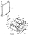
- FIG. 9 illustrates a top, front, side isometric view of a cable management device 900 in a closed configuration and holding electrical devices 750 and 751, according to a fifth embodiment.
- FIG. 10 illustrates a top, back, side isometric view of cable management device 900 in the closed configuration, according to the fifth embodiment.
- a cable management device 900 can include: (a) a housing 901 defining an interior space (not shown) and having one or more apertures (not shown) extending from an exterior 904 of housing 901 to the interior space; (b) one or more electrical outlets (not shown); (c) one or more solar panels 1064 at exterior 904 and electrically coupled to the one or more electrical outlets. Cable management device 900 can be configured to support electrical devices 750 and 751.
- Housing 901 can include: (a) a stationary portion 910; (b) cover 720 hingedly coupled to stationary portion 910; and (c) hinge 630 coupling cover 720 to stationary portion 910.
- stationary portion 910 includes: (a) wall 712; (b) a wall 913 adjacent to wall 712; (c) a wall 914 adjacent to wall 712 and spaced part and/or opposite wall 913: (d) a wall 915 have a side 935 and a side 1036 ( FIG. 10 ) opposite side 935 and adjacent to walls 712, 913, and 91.4; (e) a wall 916 adjacent to walls 913, 914, and 915 and spaced apart and/or opposite wall 712.
- Cover 720 can be hingedly attached to at least one of walls 913, 914, and 916.
- a height of wall 915 is greater than the heights of wall 913, wall 914, and cover 720.
- Solar panels 1064 and connection mechanisms 762 can be located at side 1036. In other embodiments, ail of wall 915 can be part of solar panels 764.
- FIG. 11 illustrates a flow chart 1100 for an embodiment of a method of providing a cable management device.
- the cable management device can be similar or identical to cable management devices 100, 400, 500, 700, or 900 of FIGs. 1 , 4 , 5 , 7 , and 9 respectively.
- Flow chart 1100 includes a step 1110 of providing a receptacle with one or more apertures.
- the receptacle can be identical or similar to housing 101, 401, 501, 701, or 901 of FIGs. 1 , 4 , 5 , 7 , and 9 , respectively.
- the one or more apertures can be identical or similar to apertures 103 or 803 of FIGs. 1 and 8 , respectively, or gap 305 of FIG. 3 .
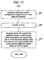
- FIG. 12 illustrates a flow chart 1200 of step 1110 ( FIG. 11 ) of providing a receptacle with one or more apertures, according to an embodiment.
- Flow chart 1200 of FIG. 12 includes a procedure 1250 of providing a stationary portion configured to support one or more electrical devices.
- the stationary portion can be identical or similar to stationary portion 110, 510, 710, or 910 of FIGs. 1 , 5 , 7 , and 9 , respectively.
- the one or more electrical devices can be identical or similar to electrical device 150 as shown in FIGs. 1, 2 , and 5 or electrical devices 750 and 751 as shown in FIGs. 7-9 .
- flow chart 1200 of FIG. 12 includes a procedure 1260 of providing a cover.
- the cover can be identical or similar to cover 120, 420, 520. or 720 of FIGs. 1 , 4 , 5 , and 7 , respectively.
- flow chart 1200 of FIG. 12 includes a procedure 1270 of hingedly attaching the cover to the stationary portion such that the stationary portion can support the one or more electrical devices when the cover is in an open position, and with the cover and the stationary portion defining an interior space.
- the cover hingedly coupled to the stationary portion can be similar or identical to coupling of the cover and the stationary portion as shown in FIGs. 1-10 .
- flow chart 1100 includes step 1120 of positioning one or more electrical outlets in the interior space such that the one or more electrical outlets can be accessed through the one or more apertures when the cover is in a closed position.
- the positioning of the one or more electrical outlets can be identical or similar to the positioning of electrical outlets 106 as shown in FIGs. 1 , 4 , 6 , or 8 ,
- FIG. 13 illustrates a flow chart 1300 for an embodiment of a method of providing a holder.
- the holder can be similar or identical to cable management device 100 or 400 as shown in FIGs. 1 and 4 , respectively.
- Flow chart 1300 of FIG. 13 includes a step 1310 of providing a receptacle including: (a) a first wall configured to hold the at least one electrical device at an external surface; and (b) a second wall spaced apart from the first wall.
- the first wall can be identical or similar to wall 112 of FIG. 1 .
- the second wall can be identical or similar to wall 116 of FIG. 1 .
- Flow chart 1300 in FIG. 13 continues with a step 1320 of providing an L-shaped component with one or more electrical outlets.
- the L-shaped component can be identical or similar to cover 120 or 420 of FIGs. 1 and 4 , respectively.
- the one or more electrical outlets can be similar or identical to electrical outlets 106 of FIGs. 1 and 4 .
- flow chart 1300 includes a step 1330 of attaching the L-shaped component to the second wall such that the L-shaped component and the one or more electrical outlets can be pivoted in relation to the second wall.
- the coupling of the L-shaped component and the second wall can be similar or identical to the coupling of cover 120 or 420 with wall 116 as shown in FIGs. 1 and 4 .
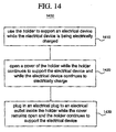
- FIG. 14 illustrates a flow chart 1400 for an embodiment of a method of using a holder.
- the holder can be identical or similar to the cable management device 100, 400, 500, 700, or 900 as shown in FIGs. 1 , 4 , 5 , 7 , and 9 , respectively.
- Flow chart 1400 of FIG. 14 includes a step 1410 of using the holder to support an electrical device while the electrical device is being electrically charged.
- the electrical device can be identical or similar to electrical device 150 as shown in FIGs. 1, 2 . and 5 or electrical devices 750 and 751 as shown in FIGs. 7-9 .
- flow chart 1400 of FIG. 14 includes a step 1420 of opening a cover of the holder while the holder continues to support the electrical device and while the electrical device continues to electrically charge.
- flow chart 1400 of FIG. 14 includes a step 1430 of plugging in an electrical plug to an electrical outlets inside the holder while the cover remains open and the bolder continues to support the electrical device.
- the cable management device can have an electrical cable configured to Couple to electrical devices 150, 750, and/or 751.
- the electrical cable can have a universal connector or a set of interchangeable connectors to allow the cable management device to connect too many different electrical devices.
- embodiments and limitations disclosed herein are not dedicated to the public under the doctrine of dedication if the embodiments and/or limitations: (1) are not expressly claimed in the claims; and (2) are or are potentially equivalents of express elements and/or limitations in the claims under the doctrine of equivalents.
Landscapes
- Engineering & Computer Science (AREA)
- Microelectronics & Electronic Packaging (AREA)
- Power Engineering (AREA)
- Architecture (AREA)
- Civil Engineering (AREA)
- Structural Engineering (AREA)
- Insertion, Bundling And Securing Of Wires For Electric Apparatuses (AREA)
- Casings For Electric Apparatus (AREA)
- Details Of Indoor Wiring (AREA)
Claims (17)
- Kabelverwaltungseinrichtung (100), konfiguriert zum Ruhen über einer Fläche und zum Halten einer oder mehrerer elektrischer Einrichtungen (150), wobei die Kabelverwaltungseinrichtung aufweist:ein Gehäuse (101), das einen Innenraum definiert und eine oder mehrere von einem Äußeren des Gehäuses zum Innenraum sich erstreckende Öffnungen aufweist, wobei das Gehäuse aufweist:einen stationären Teil (110), undeine Abdeckung (120), die eine Innenfläche aufweist, wobei die Abdeckung gelenkig an dem stationären Teil angebracht ist, undeinen oder mehrere elektrische Ausgänge (106), die an der Innenfläche der Abdeckung lokalisiert sind, wobeider stationäre Teil aufweist:eine erste Wand mit einem Haltemechanismus, undeine zweite Wand, die getrennt ist von der ersten Wand und konfiguriert ist zum Ruhen über der Fläche, wobeider Haltemechanismus die eine oder mehreren elektrischen Einrichtungen hält,die Abdeckung konfiguriert ist zum Bewegen zwischen einer ersten Position, bei der die Abdeckung den Innenraum im Wesentlichen einschließt, und einer zweiten Position, bei welcher der Innenraum freigegeben ist,die eine oder mehreren Öffnungen Zugang vom Äußeren des Gehäuses zum Innenraum bereitstellen, wenn die Abdeckung in der ersten Position ist, unddas Gehäuse derart konfiguriert ist, dass die Abdeckung zwischen der ersten Position und der zweiten Position bewegt werden kann, während der Haltemechanismus das Halten der einen oder mehreren elektrischen Einrichtungen beibehält und die zweite Wand über der Fläche ruht.
- Kabelverwaltungseinrichtung nach Anspruch 1, wobei:das Gehäuse derart konfiguriert ist, dass die eine oder mehreren elektrischen Ausgänge durch die eine oder mehreren Öffnungen zugänglich sind, wenn die Abdeckung in der ersten Position ist.
- Kabelverwaltungseinrichtung nach einem der vorhergehenden Ansprüche, wobei die Abdeckung an der zweiten Wand gelenkig angebracht ist.
- Kabelverwaltungseinrichtung nach einem der vorhergehenden Ansprüche, wobei:die Abdeckung gegenüber der Innenfläche eine Außenfläche am Äußeren des Gehäuses aufweist.
- Kabelverwaltungseinrichtung nach einem der vorhergehenden Ansprüche, wobei:die Abdeckung aufweist:einen ersten Abschnitt, undeinen zweiten Abschnitt, der im Innenraum lokalisiert ist, wenn die Abdeckung in der ersten Position ist, wobeider erste Abschnitt einen Teil des Äußeren des Gehäuses umfasst, undder eine oder die mehreren elektrischen Ausgänge an wenigstens dem ersten Abschnitt der Abdeckung und im Innenraum lokalisiert sind, wenn die Abdeckung in der ersten Position ist.
- Kabelverwaltungseinrichtung nach Anspruch 1, 2, 3 oder 4, wobei:die Abdeckung aufweist:einen ersten Abschnitt, undeinen zweiten Abschnitt, der im Innenraum lokalisiert ist, wenn die Abdeckung in der ersten Position ist, undder erste Abschnitt an einer ersten Verbindungsstelle an den zweiten Abschnitt gekoppelt ist derart, dass der erste Abschnitt im Wesentlichen senkrecht zum zweiten Abschnitt ist.
- Kabelverwaltungseinrichtung nach Anspruch 5 oder 6, wobei:die Abdeckung an der ersten Verbindungsstelle an den stationären Teil gekoppelt ist.
- Kabelverwaltungseinrichtung nach Anspruch 5 oder 6, wobei:der erste Abschnitt einen Teil des Äußeren des Gehäuses umfasst.
- Kabelverwaltungseinrichtung nach einem der vorhergehenden Ansprüche, wobei:die Abdeckung ein erstes Ende und ein zweites Ende gegenüber dem ersten Ende aufweist,das erste Ende der Abdeckung an dem stationären Abschnitt gelenkig angebracht ist,das Gehäuse derart konfiguriert ist, dass ein Spalt zwischen dem zweiten Ende der Abdeckung und dem stationären Teil existiert, wenn die Abdeckung in der ersten Position ist, undder Spalt eine von der einen oder den mehreren Öffnungen umfasst.
- Kabelverwaltungseinrichtung nach einem der vorhergehenden Ansprüche, wobei:das Gehäuse derart konfiguriert ist, dass jede von der einen oder den mehreren Öffnungen einem oder mehreren Kabeln ermöglichen kann, in den Innenraum des Gehäuses einzutreten.
- Kabelverwaltungseinrichtung nach einem der vorhergehenden Ansprüche, wobei:der Haltemechanismus eine Außenfläche aufweist,die Außenfläche des Haltemechanismus' von wenigstens einer Rippe oder wenigstens einer Nut wenigstens eines aufweist, unddie Außenfläche des Haltemechanismus' Teil des Äußeren des Gehäuses ist.
- Kabelverwaltungseinrichtung nach einem der vorhergehenden Ansprüche, weiter aufweisend:ein oder mehrere Solarplatten zum Bereitstellen elektrischer Energie dem einen oder den mehreren elektrischen Ausgängen.
- Verfahren (1100) zur Bereitstellung einer Kabelverwaltungseinrichtung, aufweisend:Bereitstellen eines Gehäuses (101), definierend einen Innenraum und aufweisend eine oder mehrere sich von einem Äußeren des Gehäuses zum Innenraum erstreckende Öffnungen, wobei das Gehäuse beinhaltet:Bereitstellen eines stationären Teils (110), konfiguriert zum Ruhen über einer Fläche und zum Halten einer oder mehrerer elektrischer Einrichtungen, wobei der stationäre Teil eine erste Wand mit einem Haltemechanismus und eine zweite Wand räumlich getrennt von der ersten Wand und konfiguriert zum Ruhen über der Fläche aufweist,Bereitstellen einer Abdeckung (120), die eine Innenfläche aufweist, undgelenkiges Abringen der Abdeckung an dem stationären Teil derart, dass der stationäre Teil die eine oder mehreren elektrischen Einrichtungen halten kann, wenn die Abdeckung in einer ersten Position ist, bei der die Abdeckung den Innenraum im Wesentlichen einschließt, und wenn die Abdeckung in einer zweiten Position ist, bei welcher der Innenraum freigegeben ist, undPositionieren eines oder mehrerer elektrischer Ausgänge (106) an der Innenfläche der Abdeckung derart, dass der eine oder die mehreren elektrischen Ausgänge mit einem Kabel durch die eine oder mehreren Öffnungen zugänglich sind, wenn die Abdeckung in der ersten Position ist.
- Kabelverwaltungseinrichtung nach einem der Ansprüche 6, 7 oder 8, wobei:der erste Abschnitt an der ersten Verbindungsstelle einen Winkel mit dem zweiten Abschnitt bildet, undder Winkel größer als oder gleich 80 Grad und kleiner als oder gleich 110 Grad ist.
- Kabelverwaltungseinrichtung nach Anspruch 6, 7 oder 8, wobei:der erste Abschnitt an der ersten Verbindungsstelle einen Winkel mit dem zweiten Abschnitt bildet, undder Winkel größer als oder gleich 87 Grad und kleiner als oder gleich 93 Grad ist.
- Kabelverwaltungseinrichtung nach einem der Ansprüche 1 bis 12, 14 oder 15, wobei:die Abdeckung an dem stationären Teil durch ein Gelenk gelenkig angebracht ist, unddas Gelenk von einem mitlaufenden Gelenk oder einem Schlitz-und-Stift-Gelenk wenigstens eines aufweist.
- Kabelverwaltungseinrichtung nach einem der Ansprüche 1 bis 10, 14 oder 15, wobei:der Haltemechanismus eine Außenfläche aufweist,die Außenfläche eine Fläche hoher Reibung aufweist unddie Außenfläche Teil des Äußeren des Gehäuses ist
Applications Claiming Priority (1)
| Application Number | Priority Date | Filing Date | Title |
|---|---|---|---|
| US84920006P | 2006-10-03 | 2006-10-03 |
Publications (3)
| Publication Number | Publication Date |
|---|---|
| EP1933435A2 EP1933435A2 (de) | 2008-06-18 |
| EP1933435A3 EP1933435A3 (de) | 2009-12-16 |
| EP1933435B1 true EP1933435B1 (de) | 2012-01-04 |
Family
ID=39111304
Family Applications (1)
| Application Number | Title | Priority Date | Filing Date |
|---|---|---|---|
| EP07253929A Not-in-force EP1933435B1 (de) | 2006-10-03 | 2007-10-03 | Zur Unterstützung eines oder mehrerer Elektrogeräte konfigurierte Kabelverwaltungsvorrichtung sowie Herstellungs- und Verwendungsverfahren dafür |
Country Status (4)
| Country | Link |
|---|---|
| EP (1) | EP1933435B1 (de) |
| AT (1) | ATE540455T1 (de) |
| AU (1) | AU2007221798B2 (de) |
| TW (1) | TW200838051A (de) |
Families Citing this family (2)
| Publication number | Priority date | Publication date | Assignee | Title |
|---|---|---|---|---|
| CN105960119A (zh) * | 2016-05-31 | 2016-09-21 | 深圳市双赢伟业科技股份有限公司 | 插接式交换机支架 |
| CN112367795A (zh) * | 2020-10-28 | 2021-02-12 | 湖北智建芯云科技有限公司 | 一种弹性受力式可调节多功能算力架 |
Family Cites Families (7)
| Publication number | Priority date | Publication date | Assignee | Title |
|---|---|---|---|---|
| US5218169A (en) * | 1990-03-30 | 1993-06-08 | Randolph-Rand Corporation | Child care electrical outlet safety cover |
| JP2001149130A (ja) * | 1999-11-26 | 2001-06-05 | Olympus Optical Co Ltd | 充電用カメラケース |
| WO2001089057A1 (en) * | 2000-05-16 | 2001-11-22 | Solco Alphatronics Co., Ltd. | A battery charging device for various type of cellular phone |
| US6419426B1 (en) | 2000-07-05 | 2002-07-16 | Advanced Integration Technology, Inc. | Numeric controlled drilling jig-multiple-axis aerospace drilling machine |
| US6982542B2 (en) * | 2001-06-22 | 2006-01-03 | Denis Graham Reah | Accessory for use with mobile telephones |
| KR20030083662A (ko) * | 2003-10-06 | 2003-10-30 | 권혁대 | 살균기능 및 조명기능을 갖는 휴대폰 충전장치 |
| WO2006022466A1 (en) * | 2004-08-23 | 2006-03-02 | Hyo-Jeong Baek | Sterilizing and charging apparatus for mobile communication terminals |
-
2007
- 2007-10-03 AU AU2007221798A patent/AU2007221798B2/en not_active Ceased
- 2007-10-03 TW TW096137034A patent/TW200838051A/zh unknown
- 2007-10-03 EP EP07253929A patent/EP1933435B1/de not_active Not-in-force
- 2007-10-03 AT AT07253929T patent/ATE540455T1/de active
Also Published As
| Publication number | Publication date |
|---|---|
| EP1933435A3 (de) | 2009-12-16 |
| EP1933435A2 (de) | 2008-06-18 |
| AU2007221798A1 (en) | 2008-04-17 |
| TW200838051A (en) | 2008-09-16 |
| ATE540455T1 (de) | 2012-01-15 |
| AU2007221798B2 (en) | 2011-03-31 |
Similar Documents
| Publication | Publication Date | Title |
|---|---|---|
| US7553174B2 (en) | Cable management device configured to support one or more electrical devices and methods of manufacturing and using the same | |
| US9551454B2 (en) | Device holder | |
| US9153986B1 (en) | Versatile plug and play charging station | |
| US8686683B2 (en) | Charge clip | |
| US9124105B2 (en) | Wireless charging shelf | |
| US9819202B2 (en) | Apparatus for charging batteries of devices at a selected DC voltage | |
| US7399201B1 (en) | Electronic device charging platform and portable electrical outlet enclosure | |
| US9007018B2 (en) | Portable device charger | |
| US20080272258A1 (en) | Device for rechargeable electrical apparatus retainer unit | |
| US8512072B1 (en) | Utility receptacle apparatus for use with a work surface or similar article | |
| US20100176762A1 (en) | Vertical Charging Apparatus | |
| US20130244475A1 (en) | Wall outlet with retractable usb charging cable connected to a usb port within a wall | |
| US10355424B2 (en) | Electronic device holder | |
| US20140217981A1 (en) | Charging Station for Portable Electronic Devices | |
| US8692514B2 (en) | Charging station for portable electronic devices | |
| US20090152944A1 (en) | Power system | |
| US20050007070A1 (en) | Personal power recharging organizer | |
| EP1933435B1 (de) | Zur Unterstützung eines oder mehrerer Elektrogeräte konfigurierte Kabelverwaltungsvorrichtung sowie Herstellungs- und Verwendungsverfahren dafür | |
| US12185048B2 (en) | Earphone charger and neck-mounted portable power supply | |
| EP2278669A2 (de) | Stromversorgungsadapter | |
| GB2475467A (en) | Power supply adapter for supplying multiple devices | |
| CN214901530U (zh) | 一种充电线可拆卸的移动电源 | |
| CN223713619U (zh) | 带伸缩线组合式充电模块 | |
| CN218771330U (zh) | 充电宝 | |
| KR20100012470U (ko) | 충전기 거치대 |
Legal Events
| Date | Code | Title | Description |
|---|---|---|---|
| PUAI | Public reference made under article 153(3) epc to a published international application that has entered the european phase |
Free format text: ORIGINAL CODE: 0009012 |
|
| AK | Designated contracting states |
Kind code of ref document: A2 Designated state(s): AT BE BG CH CY CZ DE DK EE ES FI FR GB GR HU IE IS IT LI LT LU LV MC MT NL PL PT RO SE SI SK TR |
|
| AX | Request for extension of the european patent |
Extension state: AL BA HR MK RS |
|
| PUAL | Search report despatched |
Free format text: ORIGINAL CODE: 0009013 |
|
| AK | Designated contracting states |
Kind code of ref document: A3 Designated state(s): AT BE BG CH CY CZ DE DK EE ES FI FR GB GR HU IE IS IT LI LT LU LV MC MT NL PL PT RO SE SI SK TR |
|
| AX | Request for extension of the european patent |
Extension state: AL BA HR MK RS |
|
| 17P | Request for examination filed |
Effective date: 20100614 |
|
| 17Q | First examination report despatched |
Effective date: 20100702 |
|
| AKX | Designation fees paid |
Designated state(s): AT BE BG CH CY CZ DE DK EE ES FI FR GB GR HU IE IS IT LI LT LU LV MC MT NL PL PT RO SE SI SK TR |
|
| RAP1 | Party data changed (applicant data changed or rights of an application transferred) |
Owner name: BELKIN INTERNATIONAL, INC. |
|
| GRAP | Despatch of communication of intention to grant a patent |
Free format text: ORIGINAL CODE: EPIDOSNIGR1 |
|
| GRAS | Grant fee paid |
Free format text: ORIGINAL CODE: EPIDOSNIGR3 |
|
| GRAA | (expected) grant |
Free format text: ORIGINAL CODE: 0009210 |
|
| AK | Designated contracting states |
Kind code of ref document: B1 Designated state(s): AT BE BG CH CY CZ DE DK EE ES FI FR GB GR HU IE IS IT LI LT LU LV MC MT NL PL PT RO SE SI SK TR |
|
| REG | Reference to a national code |
Ref country code: GB Ref legal event code: FG4D |
|
| REG | Reference to a national code |
Ref country code: CH Ref legal event code: EP |
|
| REG | Reference to a national code |
Ref country code: AT Ref legal event code: REF Ref document number: 540455 Country of ref document: AT Kind code of ref document: T Effective date: 20120115 |
|
| REG | Reference to a national code |
Ref country code: IE Ref legal event code: FG4D |
|
| REG | Reference to a national code |
Ref country code: DE Ref legal event code: R096 Ref document number: 602007019793 Country of ref document: DE Effective date: 20120308 |
|
| REG | Reference to a national code |
Ref country code: NL Ref legal event code: VDEP Effective date: 20120104 |
|
| PG25 | Lapsed in a contracting state [announced via postgrant information from national office to epo] |
Ref country code: SI Free format text: LAPSE BECAUSE OF FAILURE TO SUBMIT A TRANSLATION OF THE DESCRIPTION OR TO PAY THE FEE WITHIN THE PRESCRIBED TIME-LIMIT Effective date: 20120104 |
|
| LTIE | Lt: invalidation of european patent or patent extension |
Effective date: 20120104 |
|
| PG25 | Lapsed in a contracting state [announced via postgrant information from national office to epo] |
Ref country code: IS Free format text: LAPSE BECAUSE OF FAILURE TO SUBMIT A TRANSLATION OF THE DESCRIPTION OR TO PAY THE FEE WITHIN THE PRESCRIBED TIME-LIMIT Effective date: 20120504 Ref country code: BG Free format text: LAPSE BECAUSE OF FAILURE TO SUBMIT A TRANSLATION OF THE DESCRIPTION OR TO PAY THE FEE WITHIN THE PRESCRIBED TIME-LIMIT Effective date: 20120404 Ref country code: LT Free format text: LAPSE BECAUSE OF FAILURE TO SUBMIT A TRANSLATION OF THE DESCRIPTION OR TO PAY THE FEE WITHIN THE PRESCRIBED TIME-LIMIT Effective date: 20120104 Ref country code: BE Free format text: LAPSE BECAUSE OF FAILURE TO SUBMIT A TRANSLATION OF THE DESCRIPTION OR TO PAY THE FEE WITHIN THE PRESCRIBED TIME-LIMIT Effective date: 20120104 Ref country code: NL Free format text: LAPSE BECAUSE OF FAILURE TO SUBMIT A TRANSLATION OF THE DESCRIPTION OR TO PAY THE FEE WITHIN THE PRESCRIBED TIME-LIMIT Effective date: 20120104 |
|
| PG25 | Lapsed in a contracting state [announced via postgrant information from national office to epo] |
Ref country code: GR Free format text: LAPSE BECAUSE OF FAILURE TO SUBMIT A TRANSLATION OF THE DESCRIPTION OR TO PAY THE FEE WITHIN THE PRESCRIBED TIME-LIMIT Effective date: 20120405 Ref country code: FI Free format text: LAPSE BECAUSE OF FAILURE TO SUBMIT A TRANSLATION OF THE DESCRIPTION OR TO PAY THE FEE WITHIN THE PRESCRIBED TIME-LIMIT Effective date: 20120104 Ref country code: PT Free format text: LAPSE BECAUSE OF FAILURE TO SUBMIT A TRANSLATION OF THE DESCRIPTION OR TO PAY THE FEE WITHIN THE PRESCRIBED TIME-LIMIT Effective date: 20120504 Ref country code: LV Free format text: LAPSE BECAUSE OF FAILURE TO SUBMIT A TRANSLATION OF THE DESCRIPTION OR TO PAY THE FEE WITHIN THE PRESCRIBED TIME-LIMIT Effective date: 20120104 Ref country code: PL Free format text: LAPSE BECAUSE OF FAILURE TO SUBMIT A TRANSLATION OF THE DESCRIPTION OR TO PAY THE FEE WITHIN THE PRESCRIBED TIME-LIMIT Effective date: 20120104 |
|
| REG | Reference to a national code |
Ref country code: AT Ref legal event code: MK05 Ref document number: 540455 Country of ref document: AT Kind code of ref document: T Effective date: 20120104 |
|
| PG25 | Lapsed in a contracting state [announced via postgrant information from national office to epo] |
Ref country code: CY Free format text: LAPSE BECAUSE OF FAILURE TO SUBMIT A TRANSLATION OF THE DESCRIPTION OR TO PAY THE FEE WITHIN THE PRESCRIBED TIME-LIMIT Effective date: 20120104 |
|
| PG25 | Lapsed in a contracting state [announced via postgrant information from national office to epo] |
Ref country code: SE Free format text: LAPSE BECAUSE OF FAILURE TO SUBMIT A TRANSLATION OF THE DESCRIPTION OR TO PAY THE FEE WITHIN THE PRESCRIBED TIME-LIMIT Effective date: 20120104 Ref country code: EE Free format text: LAPSE BECAUSE OF FAILURE TO SUBMIT A TRANSLATION OF THE DESCRIPTION OR TO PAY THE FEE WITHIN THE PRESCRIBED TIME-LIMIT Effective date: 20120104 Ref country code: RO Free format text: LAPSE BECAUSE OF FAILURE TO SUBMIT A TRANSLATION OF THE DESCRIPTION OR TO PAY THE FEE WITHIN THE PRESCRIBED TIME-LIMIT Effective date: 20120104 Ref country code: CZ Free format text: LAPSE BECAUSE OF FAILURE TO SUBMIT A TRANSLATION OF THE DESCRIPTION OR TO PAY THE FEE WITHIN THE PRESCRIBED TIME-LIMIT Effective date: 20120104 Ref country code: DK Free format text: LAPSE BECAUSE OF FAILURE TO SUBMIT A TRANSLATION OF THE DESCRIPTION OR TO PAY THE FEE WITHIN THE PRESCRIBED TIME-LIMIT Effective date: 20120104 |
|
| PLBE | No opposition filed within time limit |
Free format text: ORIGINAL CODE: 0009261 |
|
| STAA | Information on the status of an ep patent application or granted ep patent |
Free format text: STATUS: NO OPPOSITION FILED WITHIN TIME LIMIT |
|
| PG25 | Lapsed in a contracting state [announced via postgrant information from national office to epo] |
Ref country code: IT Free format text: LAPSE BECAUSE OF FAILURE TO SUBMIT A TRANSLATION OF THE DESCRIPTION OR TO PAY THE FEE WITHIN THE PRESCRIBED TIME-LIMIT Effective date: 20120104 Ref country code: SK Free format text: LAPSE BECAUSE OF FAILURE TO SUBMIT A TRANSLATION OF THE DESCRIPTION OR TO PAY THE FEE WITHIN THE PRESCRIBED TIME-LIMIT Effective date: 20120104 |
|
| 26N | No opposition filed |
Effective date: 20121005 |
|
| PG25 | Lapsed in a contracting state [announced via postgrant information from national office to epo] |
Ref country code: AT Free format text: LAPSE BECAUSE OF FAILURE TO SUBMIT A TRANSLATION OF THE DESCRIPTION OR TO PAY THE FEE WITHIN THE PRESCRIBED TIME-LIMIT Effective date: 20120104 |
|
| REG | Reference to a national code |
Ref country code: DE Ref legal event code: R097 Ref document number: 602007019793 Country of ref document: DE Effective date: 20121005 |
|
| PG25 | Lapsed in a contracting state [announced via postgrant information from national office to epo] |
Ref country code: ES Free format text: LAPSE BECAUSE OF FAILURE TO SUBMIT A TRANSLATION OF THE DESCRIPTION OR TO PAY THE FEE WITHIN THE PRESCRIBED TIME-LIMIT Effective date: 20120415 |
|
| PG25 | Lapsed in a contracting state [announced via postgrant information from national office to epo] |
Ref country code: MC Free format text: LAPSE BECAUSE OF NON-PAYMENT OF DUE FEES Effective date: 20121031 |
|
| REG | Reference to a national code |
Ref country code: CH Ref legal event code: PL |
|
| GBPC | Gb: european patent ceased through non-payment of renewal fee |
Effective date: 20121003 |
|
| REG | Reference to a national code |
Ref country code: IE Ref legal event code: MM4A |
|
| REG | Reference to a national code |
Ref country code: FR Ref legal event code: ST Effective date: 20130628 |
|
| PG25 | Lapsed in a contracting state [announced via postgrant information from national office to epo] |
Ref country code: IE Free format text: LAPSE BECAUSE OF NON-PAYMENT OF DUE FEES Effective date: 20121003 Ref country code: DE Free format text: LAPSE BECAUSE OF NON-PAYMENT OF DUE FEES Effective date: 20130501 Ref country code: LI Free format text: LAPSE BECAUSE OF NON-PAYMENT OF DUE FEES Effective date: 20121031 Ref country code: GB Free format text: LAPSE BECAUSE OF NON-PAYMENT OF DUE FEES Effective date: 20121003 Ref country code: CH Free format text: LAPSE BECAUSE OF NON-PAYMENT OF DUE FEES Effective date: 20121031 |
|
| REG | Reference to a national code |
Ref country code: DE Ref legal event code: R119 Ref document number: 602007019793 Country of ref document: DE Effective date: 20130501 |
|
| PG25 | Lapsed in a contracting state [announced via postgrant information from national office to epo] |
Ref country code: FR Free format text: LAPSE BECAUSE OF NON-PAYMENT OF DUE FEES Effective date: 20121031 |
|
| PG25 | Lapsed in a contracting state [announced via postgrant information from national office to epo] |
Ref country code: MT Free format text: LAPSE BECAUSE OF FAILURE TO SUBMIT A TRANSLATION OF THE DESCRIPTION OR TO PAY THE FEE WITHIN THE PRESCRIBED TIME-LIMIT Effective date: 20120104 |
|
| PG25 | Lapsed in a contracting state [announced via postgrant information from national office to epo] |
Ref country code: TR Free format text: LAPSE BECAUSE OF FAILURE TO SUBMIT A TRANSLATION OF THE DESCRIPTION OR TO PAY THE FEE WITHIN THE PRESCRIBED TIME-LIMIT Effective date: 20120104 |
|
| PG25 | Lapsed in a contracting state [announced via postgrant information from national office to epo] |
Ref country code: LU Free format text: LAPSE BECAUSE OF NON-PAYMENT OF DUE FEES Effective date: 20121003 |
|
| PG25 | Lapsed in a contracting state [announced via postgrant information from national office to epo] |
Ref country code: HU Free format text: LAPSE BECAUSE OF FAILURE TO SUBMIT A TRANSLATION OF THE DESCRIPTION OR TO PAY THE FEE WITHIN THE PRESCRIBED TIME-LIMIT Effective date: 20071003 |