EP1933342A1 - Tore et dispositif de détection differentielle - Google Patents
Tore et dispositif de détection differentielle Download PDFInfo
- Publication number
- EP1933342A1 EP1933342A1 EP07354051A EP07354051A EP1933342A1 EP 1933342 A1 EP1933342 A1 EP 1933342A1 EP 07354051 A EP07354051 A EP 07354051A EP 07354051 A EP07354051 A EP 07354051A EP 1933342 A1 EP1933342 A1 EP 1933342A1
- Authority
- EP
- European Patent Office
- Prior art keywords
- ribbon
- end portion
- torus
- detection
- core
- Prior art date
- Legal status (The legal status is an assumption and is not a legal conclusion. Google has not performed a legal analysis and makes no representation as to the accuracy of the status listed.)
- Granted
Links
Images

Classifications
-
- H—ELECTRICITY
- H01—ELECTRIC ELEMENTS
- H01F—MAGNETS; INDUCTANCES; TRANSFORMERS; SELECTION OF MATERIALS FOR THEIR MAGNETIC PROPERTIES
- H01F38/00—Adaptations of transformers or inductances for specific applications or functions
- H01F38/20—Instruments transformers
- H01F38/22—Instruments transformers for single phase AC
- H01F38/28—Current transformers
- H01F38/30—Constructions
-
- H—ELECTRICITY
- H01—ELECTRIC ELEMENTS
- H01F—MAGNETS; INDUCTANCES; TRANSFORMERS; SELECTION OF MATERIALS FOR THEIR MAGNETIC PROPERTIES
- H01F27/00—Details of transformers or inductances, in general
- H01F27/24—Magnetic cores
- H01F27/25—Magnetic cores made from strips or ribbons
-
- H—ELECTRICITY
- H01—ELECTRIC ELEMENTS
- H01H—ELECTRIC SWITCHES; RELAYS; SELECTORS; EMERGENCY PROTECTIVE DEVICES
- H01H83/00—Protective switches, e.g. circuit-breaking switches, or protective relays operated by abnormal electrical conditions otherwise than solely by excess current
- H01H83/14—Protective switches, e.g. circuit-breaking switches, or protective relays operated by abnormal electrical conditions otherwise than solely by excess current operated by imbalance of two or more currents or voltages, e.g. for differential protection
- H01H83/144—Protective switches, e.g. circuit-breaking switches, or protective relays operated by abnormal electrical conditions otherwise than solely by excess current operated by imbalance of two or more currents or voltages, e.g. for differential protection with differential transformer
-
- H—ELECTRICITY
- H01—ELECTRIC ELEMENTS
- H01F—MAGNETS; INDUCTANCES; TRANSFORMERS; SELECTION OF MATERIALS FOR THEIR MAGNETIC PROPERTIES
- H01F27/00—Details of transformers or inductances, in general
- H01F27/34—Special means for preventing or reducing unwanted electric or magnetic effects, e.g. no-load losses, reactive currents, harmonics, oscillations, leakage fields
-
- H—ELECTRICITY
- H01—ELECTRIC ELEMENTS
- H01H—ELECTRIC SWITCHES; RELAYS; SELECTORS; EMERGENCY PROTECTIVE DEVICES
- H01H83/00—Protective switches, e.g. circuit-breaking switches, or protective relays operated by abnormal electrical conditions otherwise than solely by excess current
- H01H83/14—Protective switches, e.g. circuit-breaking switches, or protective relays operated by abnormal electrical conditions otherwise than solely by excess current operated by imbalance of two or more currents or voltages, e.g. for differential protection
- H01H83/144—Protective switches, e.g. circuit-breaking switches, or protective relays operated by abnormal electrical conditions otherwise than solely by excess current operated by imbalance of two or more currents or voltages, e.g. for differential protection with differential transformer
- H01H2083/146—Provisions for avoiding disadvantages of having asymetrical primaries, e.g. induction of a magnetic field even by zero difference current
Definitions
- the invention relates to the differential interruption of electrical equipment, and in particular the reliability of the high-current trip.
- the invention relates to a toroid used for the detection of differential currents and the optimization of its geometry to reduce parasitic secondary signal generation.
- the invention also relates to a differential detection device and immune protection against inadvertent tripping.
- the vector sum of the departure and return currents should be zero; however, malfunctions may occur, such as a ground fault, and a residual differential current between the line conductors remains.
- the electrical line to be verified is surrounded by a magnetic permeability ring greater than that of the air which concentrates the eventual residual magnetic field.
- a so-called secondary winding around the ring will then be the source of a voltage proportional to the magnetic field in the ring, the signal of which makes it possible to determine the differential primary intensity in the conductors of the line.
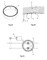
- the detection rings are thus in the form of cores 2, illustrated in Figures 1A and 1B formed of a ribbon 4 of high magnetic permeability material wound on itself.
- the ribbon 4 is of substantially constant section; its length allows the formation of a number of turns, or layers, 6 i depending on the desired capabilities of the ring, between one end 8 of the ribbon becoming an inner end of the core 2, and the other.
- the torus 2 is provided with a secondary winding 10, the turns of which, in a variable number, extend in the frame shown in FIG. figure 1C 360 °.
- the torus 2 is positioned around the line to be checked which, in the illustrated case, consists of two copper bars 12; it is understood that this example is illustrative and that the two bars 12 can in particular be replaced by the primary winding of four son of a three-phase supply with neutral as described in FR 2,749,987 , or any other embodiment.
- a secondary signal is detected in the winding 10 by the processing means 14 which can give an estimate of the secondary signal or the corresponding differential primary current. If a threshold is reached, in particular 30 mA for the primary differential current, a trip relay 16 sends a signal to cut-off systems associated with the primary conductors 12, in order to disconnect the installation concerned.
- the invention aims to overcome the drawbacks of existing systems and in particular to avoid erroneous detection of differential currents that may cause inadvertent tripping of a switchgear.
- the geometry of the detection core is optimized so that the magnetic flux passing through the core is homogenized, and does not generate parasitic secondary signals.
- the invention relates to a torus that can be used for the differential detection in which one of the end portions of the ribbon forming the core is provided with means allowing the magnetic flux to flow more homogeneously, being distributed over an upper length of turn.
- the torus according to the invention comprises a ribbon of magnetic material of substantially constant section and wound, advantageously circularly, to form a succession of turns, which are contiguous to each other by opposite sides of the ribbon.
- the ribbon comprises two ends with associated end portions of predetermined length, advantageously corresponding to a torus turn. At least one of the end portions, corresponding to and extending the inner end of the ribbon in the torus, is provided with means for homogenizing the magnetic flux.
- the homogenization of the magnetic flux is obtained by a modification, and in particular a gradual decrease, preferably a continuous decay, of the apparent density of magnetic material in the volume defined by the ribbon at the end portion and the turn which is adjacent to it in the presence of the homogenization means, with respect to the same value without said homogenization means.
- the homogenization means modify the magnetic coupling between the end portion and the turn adjacent thereto, so that this coupling is increasing from the end.
- the decrease of the relative density can be obtained by "lightening" of the end portion, by removal or reduction in material of the section and / or the surface of the ribbon, that is to say more generally a lightening element.
- the flow homogenization means may for example consist of a recess within the ribbon on the end portion, such as a hole, which may in particular be triangular, so that the end portion contains a decreasing amount of magnetic material. towards the end.
- the recess may be formed of a plurality of orifices, preferably transverse to the ribbon, and of increasing length towards the end of the ribbon.
- the lightening member may be made by cutting the ribbon at an edge of the end portion, or its edges, thereby forming a tip toward the end concerned. A decrease in thickness would also be possible.
- the homogenization means can in particular take the form of a wedge inserted between the end of the ribbon and the adjacent turn.
- the shim is inserted a distance corresponding to the end portion and its profile is adapted for a steady progression in the spacing between the turns. It is also possible to position several spacers of different heights at different levels between the inner turn and the adjacent turn.
- the invention furthermore relates to a device for detecting differential currents comprising a toroid as defined above, surrounded, preferably over its entire circumference, by a secondary winding, and associated with means for processing the secondary signal supplied by said winding. , signal representative of a differential primary current inside the toroid.
- the invention in another aspect, relates to a device for differential breaking of a primary conductor line, preferably integrated.
- the apparatus comprises a device for detecting differential currents as defined above, the primary conductors associated with a cutoff system traversing the torus of the detection device, and a tripping relay controlling the cutoff system according to the data from the processing means of the detection device.
- FIGS. 1A, 1B and 1C already described, show a differential detection torus according to the state of the art and a switchgear.
- the figure 2 illustrates a first embodiment of the invention.
- FIGS. 4A and 4B represent an alternative embodiment of the figure 3 .
- the inventors have found that one of the causes of inadvertent generation of secondary signals relates to the shape of the torus 2 of detection.
- the magnetic flux B from the primary circuit 12 passes through the torus 2 following the layers 6 i of magnetic tape; the very thin air gaps existing between each turn 6 i slow the passage of the flow B from one layer of material to another.
- the flow B flowing in the first layer 6 1 must pass into the second 6 2 , creating a local increase in flux that can not always be absorbed by the following layers 6 i and causes saturation fast of the adjacent layer 6 2 .
- This saturation not symmetrical with respect to the conductors 12, unbalances the magnetic field B of the core 2, causing the appearance of a secondary signal in the winding 10.
- the detection means 14 can deduce, for a primary current of the order of 400 A single phase in the conductors 12, a primary differential current of the order of 12-15 mA, c ' that is, 50% of the conventional trigger.
- the invention proposes to locally reduce the flow irregularity caused by the end of the ribbon 8 by the presence of homogenization means at the corresponding end portion 18 of the ribbon 4.
- the homogenizing means are such that the density of magnetic material (component ribbon 4) present in the volume delimited by the end portion 18 provided with said homogenizing means and the adjacent turn 6 2 (considering for each non-contiguous faces of the ribbon 4) relative to the same volume without the homogenization means decreases gradually towards the end 8. In this way, the magnetic coupling between the end portion 18 and the turn 6 2 increases gradually from the end 8, and its distribution is more homogeneous.
- the homogenization means can take different forms, which can be combined within the same torus 2 and / or accumulated on the same end portion 18; although the various embodiments are presented in relation to the inner end 8 of the torus 2 where the majority of the magnetic flux is concentrated, the homogenization means may concern both ends of the ribbon.
- the preferred embodiments relate to the distribution of the passage of the magnetic flux from the first to the second turn over the entire inner circumference of the core 2; it would however also be possible, in particular according to the length of the secondary winding 10, to arrange the homogenization means on only a part of the circumference of the core 2, for example over at least 45 ° or 90 ° of arc, or even on a turn, or, in some cases, to develop the homogenization means on more than one turn, for example two turns 6 1 , 6 2 of ribbon 4. It should also be understood that, although represented circular, the The winding of the ribbon 4 forming the core 2 is not limited to this geometrical shape and the known alternatives, such as an oblong or rectangular shape, for the differential detection cores are included in this term.
- the homogenization means increase the volume between the end portion 18 and the ribbon 4 of the adjacent turn 6 2 by the spacing of the end portion 18: see figure 2 .
- the volume delimited by the ribbon 4 of the two adjacent turns 6 1 , 6 2 at the end portion 18 is then greater than the corresponding volume without separation due to the homogenizing means, for the same quantity of magnetic material, and the relative density of magnetic material decreases.
- the first turn 6 1 is separated from the adjacent turn 2 , and this over a length of end portion 18, preferably equal to one turn; as the reluctance between the first layer 6 1 and the second 6 2 depends on their spacing (and therefore increases), the flow B transiting from the first turn 6 1 to the second 6 2 is gradually limited.
- the nonmagnetic wedge 20 is made of plastic, of a height of the order of the thickness of the ribbon 4, or half; in particular, the shim 20 has a height of the order of 0.1 mm at the end 8 of a ribbon 4 with a thickness of 100 to 200 ⁇ m for a torus diameter 2 of the order of 4 cm, for example for a torus 2 as previously presented.
- the joining between turns 6 i of the core 2 is retained, and the decrease in inhomogeneities of flux is achieved by a local modification of the shape of the ribbon 4, thanks to the presence of a element of lightening.
- This embodiment is advantageous because it can be implemented upstream: preferably, the actions on the end portion 18 of the ribbon 4 are performed before shaping the core 2, the ribbon 4 being flat, and before the possible annealing phases in a magnetic field that provide the magnetic materials their properties.
- the tape 4 once altered is meanwhile wound in the usual way in the form of torus 2.
- the homogenization means are made by a gradient of the thickness of the ribbon 4 towards the end 8: the usually uniform section of the ribbon 4 is modified on the part of end 18 by cutting or mechanical stress. This results in a decrease in thickness which allows a reduction of field dissymmetries by its distribution throughout the end portion 18.
- the amount of material present is less for the same surface of the ribbon and the density of the material in the space delimited by two thicknesses of ribbon 4 decreases relatively.
- this variant can be difficult to achieve, and a second variant, possibly in combination with the first, recommends performing the lightening material of the end portion 18 in the direction of the width of the ribbon 4 rather than its thickness, gradually reducing its useful width.
- the ribbon 4 is bevelled towards the end 8 to form a substantially triangular tip 28: the homogenizing means 30 are then identified by the "empty" portion complementary to the tip 28.
- the width of the ribbon in the end portion 18 thus gradually decreases, which allows a gradual transfer of magnetic flux B from the first turn 6 1 to the second 6 2 ; the local saturation of the second layer 6 2 is avoided, considerably limiting the parasitic secondary signals and therefore the false differential primary currents.
- the defect in the distribution of the magnetic field B due to the passage of a turn 6 1 to the other 6 2 is actually averaged over the torus 2, and no longer concentrated in a single point 8.
- the lightening element concerns only one side of the ribbon, as illustrated: for a narrow ribbon 4 and a torus 2 of a consequent diameter in which it is desired to form an end portion 18 of length corresponding to the first turn 6 1 , the beveling of a only side of the ribbon 4 increases the cutting angle for more accuracy and ease.
- the available sampling means and the size of the ribbon 4 it is possible to cut the end portion on its two edges, for example by positioning the end 8 at the center of the ribbon 4; this embodiment may also be preferred in the case of a direct manufacture of the ribbon 4 with a profiled end 18.
- the profiled end 28 of the ribbon 4 can twist at the cut.
- the twisted part can be cut or glued to the second layer 6 2 .
- a recess 40 for example of triangular shape, can be created in the end portion 18: the strip of material 42 remaining at the end of the recess 40 at the end 8 can be used to maintain the first turn 6 1 during shaping torus 2, for example by hanging on an axis to wind the ribbon 4.
- the recess 40 is formed by a plurality of orifices 44 i , for example crosswise in the width, which are inscribed therein: see Figure 4B .
- the decrease in relative density is here less regular than in the other embodiments, this option can be particularly advantageous in terms of manufacturing, by "punching" for example the ribbon 4 on the end portion 18.
- the torus 2 according to the invention may be used in any detection system differential 2, 10, 14, in particular for an interruption device as illustrated in FIG. figure 1C .
- the shape and the homogenization length of the stream can be optimized depending on the magnetic material chosen, the expected nominal current, the shape of the torus considered, etc.
Landscapes
- Engineering & Computer Science (AREA)
- Power Engineering (AREA)
- Transformers For Measuring Instruments (AREA)
- Measuring Instrument Details And Bridges, And Automatic Balancing Devices (AREA)
- Investigating Or Analyzing Materials By The Use Of Magnetic Means (AREA)
- Retarders (AREA)
- Analysing Materials By The Use Of Radiation (AREA)
- Measuring Magnetic Variables (AREA)
Abstract
Description
- L'invention concerne l'interruption différentielle d'appareillages électriques, et notamment la fiabilité du déclenchement à fort courant d'excitation.
- Plus généralement, l'invention se rapporte à un tore utilisé pour la détection de courants différentiels et à l'optimisation de sa géométrie pour diminuer la génération de signal secondaire parasite.
- L'invention concerne également un dispositif de détection différentielle et de protection immunisé contre des déclenchements intempestifs.
- Pour toute ligne électrique, la somme vectorielle des courants de départ et de retour devrait être nulle ; il arrive cependant que des dysfonctionnements surviennent, par exemple un défaut de la mise à la terre, et qu'un courant différentiel résiduel entre les conducteurs de la ligne subsiste. Afin de détecter de tels courants, parfois également appelés homopolaires ou de fuite, il est usuel de faire appel au champ magnétique coaxial concentrique émis par tout conducteur traversé par un courant : la ligne électrique à vérifier est entourée par un anneau de perméabilité magnétique supérieure à celle de l'air qui concentre l'éventuel champ magnétique résiduel. Un bobinage dit secondaire autour de l'anneau sera alors la source d'une tension électrique proportionnelle au champ magnétique dans l'anneau, dont le signal permet de déterminer l'intensité primaire différentielle dans les conducteurs de la ligne.
- Les propriétés magnétiques de l'anneau imposent des matériaux spécifiques, souvent disponibles uniquement en faibles épaisseurs, qui sont ensuite superposées. Selon une option classique, les anneaux de détection se présentent ainsi sous forme de tores 2, illustrés en
figures 1A et 1B , formés d'un ruban 4 de matériau de perméabilité magnétique élevée enroulé sur lui-même. Le ruban 4 est de section sensiblement constante ; sa longueur permet la formation d'un nombre de spires, ou couches, 6i dépendant des capacités souhaitées de l'anneau, entre une extrémité 8 du ruban devenant une extrémité interne du tore 2, et l'autre. - Pour former un dispositif de détection et d'interruption différentielle, le tore 2 est doté d'un enroulement secondaire 10, dont les spires, en nombre variable, s'étendent dans le cadre représenté en
figure 1C sur 360°. Le tore 2 est positionné autour de la ligne à vérifier qui, dans le cas illustré, consiste en deux barreaux 12 en cuivre ; il est entendu que cet exemple est illustratif et que les deux barreaux 12 peuvent notamment être remplacés par l'enroulement primaire de quatre fils d'une alimentation triphasée avec neutre comme décrit dansFR 2 749 987 - En présence d'une différence de courant entre les conducteurs 12 de la ligne, un signal secondaire est détecté dans l'enroulement 10 par les moyens de traitement 14 qui peuvent donner une estimation du signal secondaire ou du courant primaire différentiel correspondant. Si un seuil est atteint, notamment 30 mA pour le courant différentiel primaire, un relai de déclenchement 16 envoie un signal à des systèmes de coupure associés aux conducteurs primaires 12, afin de déconnecter l'installation considérée.
- En théorie, lorsque les barreaux 12 sont centrés dans le tore 2 et traversés par deux courants opposés, leurs champs magnétiques induits s'annulent dans le tore 2 et aucun signal n'est détecté dans le bobinage secondaire 10 ; cependant, en particulier en présence d'un fort courant primaire, il peut arriver qu'un signal secondaire soit malgré tout généré. Ce type de signal secondaire parasite, correspondant à un faux courant primaire différentiel, peut notamment être causé par une dissymétrie magnétique ou géométrique de l'ensemble de détection 2, 10, 12.
- Il est important que les faux courants différentiels détectés n'entraînent pas de déclenchement intempestif des installations. Différentes pistes ont été explorées pour minimiser leurs effets, par exemple l'association à un blindage décrite dans le document
FR 2 799 840 FR 2 749 987 - Parmi autres avantages, l'invention vise à pallier des inconvénients des systèmes existants et notamment à éviter une détection erronée de courants différentiels pouvant occasionner un déclenchement intempestif d'un appareil de coupure. A cette fin, la géométrie du tore de détection est optimisée de sorte que le flux magnétique traversant le tore soit homogénéisé, et ne génère pas de signaux secondaires parasites.
- Sous un de ses aspects, l'invention concerne un tore susceptible d'être utilisé pour la détection différentielle dans lequel une des parties d'extrémité du ruban formant le tore est dotée de moyens permettant au flux magnétique de circuler de façon plus homogène, en étant réparti sur une longueur supérieure de spire.
- Le tore selon l'invention comprend un ruban de matériau magnétique de section sensiblement constante et enroulé, avantageusement de façon circulaire, pour former une succession de spires, qui sont accolées entre elles par des faces opposées du ruban. Le ruban comprend deux extrémités auxquelles sont associées des parties d'extrémité de longueur prédéterminée, avantageusement correspondant à un tour de tore. Une au moins des parties d'extrémité, correspondant à et prolongeant l'extrémité interne du ruban dans le tore, est munie de moyens permettant d'homogénéiser le flux magnétique. L'homogénéisation du flux magnétique est obtenue par une modification, et notamment une diminution graduelle, de préférence une décroissance continue, de la densité apparente de matériau magnétique dans le volume défini par le ruban au niveau de la partie d'extrémité et la spire qui y est adjacente en présence des moyens d'homogénéisation, par rapport à la même valeur sans lesdits moyens d'homogénéisation. En d'autres termes, les moyens d'homogénéisation modifient le couplage magnétique entre la partie d'extrémité et la spire qui lui est adjacente, de sorte que ce couplage est croissant depuis l'extrémité.
- En particulier, la diminution de la densité relative, c'est-à-dire du couplage magnétique, peut être obtenue par un « allègement » de la partie d'extrémité, par un prélèvement ou une réduction en matériau de la section et/ou de la surface du ruban, c'est-à-dire plus généralement un élément d'allègement. Les moyens d'homogénéisation du flux peuvent par exemple consister en un évidement au sein du ruban sur la partie d'extrémité, comme un trou, qui peut notamment être triangulaire, de sorte que la partie d'extrémité contient une quantité décroissante de matériau magnétique vers l'extrémité. L'évidement peut être formé d'une pluralité d'orifices, de préférence transversaux au ruban, et de longueur croissante vers l'extrémité du ruban.
- Selon une alternative, l'élément d'allègement peut être réalisé par une découpe du ruban au niveau d'un bord de la partie d'extrémité, ou de ses bords, formant ainsi une pointe vers l'extrémité concernée. Une diminution de l'épaisseur serait également possible.
- La décroissance du couplage magnétique peut être réalisée par une augmentation du volume concerné, les moyens d'homogénéisation pouvant notamment prendre la forme d'une cale s'insérant entre l'extrémité du ruban et la spire adjacente. De préférence, la cale est insérée sur une distance correspondant à la partie d'extrémité et son profil est adapté pour une progression régulière dans l'écartement entre les spires. Il est envisageable également de positionner plusieurs cales de hauteurs différentes à différents niveaux entre la spire interne et la spire adjacente.
- L'invention concerne par ailleurs un dispositif de détection des courants différentiels comprenant un tore tel que défini précédemment, entouré, de préférence sur toute sa circonférence, d'un bobinage secondaire, et associé à des moyens de traitement du signal secondaire fourni par ledit bobinage, signal représentatif d'un courant primaire différentiel à l'intérieur du tore.
- Sous un autre aspect, l'invention concerne un appareil de coupure différentielle d'une ligne de conducteurs primaires, de préférence intégré. L'appareil comprend un dispositif de détection des courants différentiels tel que défini plus haut, les conducteurs primaires associés à un système de coupure traversant le tore du dispositif de détection, et un relai de déclenchement commandant le système de coupure en fonction des données issues des moyens de traitement du dispositif de détection.
- D'autres avantages et caractéristiques ressortiront plus clairement de la description qui suit de modes particuliers de réalisation de l'invention, donnés à titre illustratif et nullement limitatifs, représentés schématiquement dans les figures annexées.
- Les
figures 1A, 1B et 1C , déjà décrites, montrent un tore de détection différentiel selon l'état de la technique et un appareil de coupure. - La
figure 2 illustre un premier mode de réalisation de l'invention. - Les
figures 3A et 3B montrent un autre mode de réalisation de l'invention. - Les
figures 4A et 4B représentent une variante de réalisation de lafigure 3 . - Les inventeurs ont trouvé que l'une des causes de génération intempestive de signaux secondaires concernait la forme même du tore 2 de détection. De fait, tel qu'illustré en
figure 1B , le flux magnétique B issu du circuit primaire 12 parcourt le tore 2 en suivant les couches 6i de ruban magnétique ; les très minces entrefers existants entre chaque spire 6i freinent le passage du flux B d'une couche de matériau à l'autre. Au voisinage de l'extrémité interne 8, le flux B circulant dans la première couche 61 doit passer dans la seconde 62, créant une augmentation locale du flux qui ne peut pas toujours être absorbée par les couches suivantes 6i et entraîne la saturation rapide de la couche adjacente 62. Cette saturation, non symétrique par rapport aux conducteurs 12, déséquilibre le champ magnétique B du tore 2, entraînant l'apparition d'un signal secondaire dans le bobinage 10. - En particulier, pour un tore 2 comprenant un enroulement circulaire de périmètre 10 à 15 cm, par exemple 13 cm, d'un ruban 4 en alliage Fe-Ni d'épaisseur 100 à 200 µm, par exemple 150 microns, et de largeur 8 à 12 mm, par exemple 10 mm, les moyens de détection 14 peuvent déduire, pour un courant primaire de l'ordre de 400 A monophasé dans les conducteurs 12, un courant différentiel primaire de l'ordre de 12-15 mA, c'est-à-dire 50 % du seuil de déclenchement classique.
- L'invention se propose de diminuer localement l'irrégularité de flux causée par l'extrémité du ruban 8 grâce à la présence de moyens d'homogénéisation au niveau de la partie d'extrémité 18 correspondante du ruban 4. Les moyens d'homogénéisation sont tels que la densité de matériau magnétique (composant le ruban 4) présent dans le volume délimité par la partie d'extrémité 18 munie desdits moyens d'homogénéisation et la spire adjacente 62 (en considérant pour chacune les faces non accolées du ruban 4) par rapport au même volume sans les moyens d'homogénéisation diminue de façon graduelle vers l'extrémité 8. De cette façon, le couplage magnétique entre la partie d'extrémité 18 et la spire 62 croît de façon graduelle depuis l'extrémité 8, et sa répartition est plus homogène.
- Les moyens d'homogénéisation peuvent prendre différentes formes, qui peuvent être combinées au sein du même tore 2 et/ou cumulées sur une même partie d'extrémité 18 ; bien que les différents modes de réalisation soient présentés en relation avec l'extrémité interne 8 du tore 2 où se concentre la majorité du flux magnétique, les moyens d'homogénéisation peuvent concerner les deux extrémités du ruban. De même, les modes de réalisation préférés concernent la répartition du passage du flux magnétique de la première à la deuxième spire sur toute la circonférence intérieure du tore 2 ; il serait cependant également envisageable, selon notamment la longueur du bobinage secondaire 10, de disposer les moyens d'homogénéisation sur une partie seulement de la circonférence du tore 2, par exemple sur au moins 45° ou 90° d'arc, voire sur un demi-tour, ou, dans certains cas, de développer les moyens d'homogénéisation sur plus d'un tour, par exemple deux spires 61, 62 de ruban 4. Il faut également comprendre que, bien que représenté circulaire, l'enroulement du ruban 4 formant le tore 2 n'est pas limité à cette forme géométrique et que les alternatives connues, comme une forme oblongue ou rectangulaire, pour les tores de détection différentielle sont comprises dans ce terme.
- Selon un premier mode de réalisation, les moyens d'homogénéisation augmentent le volume entre la partie d'extrémité 18 et le ruban 4 de la spire adjacente 62 par l'écartement de la partie d'extrémité 18 : voir
figure 2 . Le volume délimité par le ruban 4 des deux spires adjacentes 61, 62 au niveau de la partie d'extrémité 18 est alors supérieur au volume correspondant sans séparation due aux moyens d'homogénéisation, pour la même quantité de matériau magnétique, et la densité volumique relative en matériau magnétique décroît. - En particulier, si une cale amagnétique 20 est placée au niveau de l'extrémité 8 du ruban 4, la première spire 61 est séparée de la spire 62 adjacente, et ce sur une certaine longueur de partie d'extrémité 18, de préférence égale à un tour ; comme la réluctance entre la première couche 61 et la seconde 62 dépend de leur écartement (et donc augmente), le flux B transitant de la première spire 61 à la seconde 62 est progressivement limité. Par exemple, contrairement à l'illustration schématique de la
figure 2 , la cale 20 non magnétique est en matière plastique, d'une hauteur de l'ordre de l'épaisseur du ruban 4, ou de la moitié ; notamment, la cale 20 a une hauteur de l'ordre de 0,1 mm à l'extrémité 8 d'un ruban 4 d'épaisseur 100 à 200 µm pour un diamètre de tore 2 de l'ordre de 4 cm, par exemple pour un tore 2 tel que présenté précédemment. - Afin d'éviter toute fluctuation et contrôler l'écartement entre les deux spires 61, 62, il peut être préférable de disposer plusieurs cales 22, 24, 26 de hauteur décroissante le long de la circonférence, tel qu'illustré en
figure 2 . Avantageusement cependant, un tel contrôle est réalisé par une cale allongée 20' (correspondant à l'ensemble des surfaces hachurées, y compris celles représentées par les signes de référence 20, 22, 24, 26), de longueur par exemple égale à un tour de ruban 4 et avec un gradient régulier d'épaisseur, plus aisée à fabriquer et mettre en place, lors de l'enroulement du ruban 4 ou par insertion entre les spires 61, 62. - Selon un deuxième mode de réalisation de l'invention, la solidarisation entre spires 6i du tore 2 est conservée, et la diminution des inhomogénéités de flux est réalisée par une modification locale de la forme du ruban 4, grâce à la présence d'un élément d'allègement. Ce mode de réalisation est avantageux car il peut être mis en place en amont : de préférence, les actions sur la partie d'extrémité 18 du ruban 4 sont effectuées avant la mise en forme du tore 2, le ruban 4 étant à plat, et avant les éventuelles phases de recuit sous champ magnétique qui procurent aux matériaux magnétiques leurs propriétés. Le ruban 4 une fois altéré est quant à lui enroulé de la façon habituelle sous forme de tore 2.
- Selon une première variante de ce deuxième mode de réalisation, non illustrée, les moyens d'homogénéisation sont réalisés par un gradient de l'épaisseur du ruban 4 vers l'extrémité 8 : la section habituellement uniforme du ruban 4 est modifiée sur la partie d'extrémité 18 par découpe ou contrainte mécanique. On obtient ainsi une décroissance de l'épaisseur qui permet une réduction des dissymétries de champ par sa répartition tout au long de la partie d'extrémité 18. Par cette variante, la quantité de matériau présente est inférieure pour la même surface de ruban et la densité volumique du matériau dans l'espace délimité par deux épaisseurs de ruban 4 diminue relativement.
- Pour certains matériaux magnétiques de faible épaisseur, cette variante peut s'avérer difficile à réaliser, et une deuxième variante, éventuellement en combinaison de la première, préconise d'effectuer l'allègement en matériau de la partie d'extrémité 18 dans le sens de la largeur du ruban 4 plutôt que de son épaisseur, en réduisant progressivement sa largeur utile. Par exemple, tel qu'illustré sur les
figures 3A et 3B , le ruban 4 est biseauté vers l'extrémité 8 pour former une pointe 28 sensiblement triangulaire : les moyens d'homogénéisation 30 sont alors identifiés par la partie « vide » complémentaire de la pointe 28. La largeur du ruban dans la partie d'extrémité 18 diminue ainsi progressivement, ce qui autorise un transfert progressif du flux magnétique B de la première spire 61 vers la seconde 62 ; la saturation locale de la seconde couche 62 est évitée, limitant considérablement les signaux secondaires parasites et donc les faux courants différentiels primaires. Le défaut dans la répartition du champ magnétique B dû au passage d'une spire 61 à l'autre 62 est de fait moyenné sur tout le tore 2, et non plus concentré en un seul point 8. - Il est préférable que l'élément d'allègement concerne un seul côté du ruban, tel qu'illustré : pour un ruban 4 étroit et un tore 2 de diamètre conséquent dans lequel on veut former une partie d'extrémité 18 de longueur correspondant à la première spire 61, le biseautage d'un seul côté du ruban 4 permet d'augmenter l'angle de découpe pour plus de précision et de facilité. Cependant, selon les moyens de prélèvement disponibles et la taille du ruban 4, il est possible de découper la partie d'extrémité sur ses deux bords, par exemple en positionnant l'extrémité 8 au centre du ruban 4 ; ce mode de réalisation peut également être préféré dans le cas d'une fabrication directe du ruban 4 avec une extrémité 18 profilée.
- Dans certains cas et pour certaines dimensions, l'extrémité profilée 28 du ruban 4 peut se vriller à la découpe. Pour fabriquer le tore 2, la partie vrillée peut être recoupée ou collée à la seconde couche 62.
- Par ailleurs, par exemple pour favoriser l'enroulement du ruban 4 et la fabrication du tore, il peut s'avérer souhaitable dans une troisième variante de procéder à des extractions de matériau à l'intérieur du ruban 4 dans sa largeur. En particulier, tel qu'illustré en
figure 4A , un évidement 40, par exemple de forme triangulaire, peut être créé dans la partie d'extrémité 18 : la bande de matériau 42 restant au bout de l'évidement 40 au niveau de l'extrémité 8 peut être utilisée pour maintenir la première spire 61 lors de la mise en forme du tore 2, par exemple en l'accrochant à un axe pour bobiner le ruban 4. - La formation de l'orifice 40 dans la partie d'extrémité 18 fait ici encore décroître la quantité de matière de la première spire 61 par rapport à la spire adjacente 62, et le flux magnétique B est forcé de passer progressivement de la spire interne 61 vers la deuxième spire 62 au long de l'évidement 40.
- Selon une alternative de cette variante, l'évidement 40 est formé par une pluralité d'orifices 44i, par exemple transversaux dans la largeur, qui y sont inscrits : voir
figure 4B . Bien que la diminution de densité relative soit ici moins régulière que dans les autres modes de réalisation, cette option peut s'avérer particulièrement avantageuse en termes de fabrication, en « poinçonnant » par exemple le ruban 4 sur la partie d'extrémité 18. - Le tore 2 selon l'invention, c'est-à-dire muni de l'un quelconque des modes de réalisation ou d'une combinaison des différentes alternatives de réalisation des moyens d'homogénéisation 20, 30, 40 présentés, peut être utilisé dans tout système de détection différentielle 2, 10, 14 existant, en particulier pour un dispositif d'interruption tel qu'illustré en
figure 1C . La forme et la longueur d'homogénéisation du flux peuvent être optimisées en fonction du matériau magnétique choisi, du courant nominal prévu, de la forme du tore considéré,... - Grâce à la présence des moyens 20, 30, 40 selon l'invention, les faux courants détectés ont été réduits considérablement, ceci sans même l'utilisation de blindage. Cet avantage est particulièrement intéressant dans le cas de dispositifs d'interruption intégrés, où l'encombrement est un critère fondamental : grâce à la solution proposée, il est possible de s'affranchir du blindage habituellement utilisé pour diminuer les signaux secondaires parasites, et donc de gagner en volume.
Claims (11)
- Tore de détection (2) comprenant un ruban (4) de matériau magnétique de section sensiblement constante enroulé de façon à former une succession de spires (6) accolées, le ruban (4) comprenant deux parties d'extrémité s'étendant sur une longueur prédéterminée à partir de chaque extrémité (8) du ruban (4), caractérisé en ce qu'au moins la partie d'extrémité (18) interne au tore (2) est munie de moyens d'homogénéisation de flux (20, 30, 40) tels que le couplage magnétique entre ladite partie d'extrémité (18) et la spire adjacente (62) diminue graduellement vers l'extrémité (8) correspondante du ruban (4).
- Tore de détection selon la revendication 1 dans lequel les moyens d'homogénéisation comprennent un élément d'allègement (30, 40) de la partie d'extrémité (18), de sorte que la quantité de matériau magnétique de ruban (4) varie sur la longueur de la partie d'extrémité (18).
- Tore de détection selon la revendication 2 dans lequel l'élément d'allègement (30) est localisé au niveau d'un bord au moins du ruban (4), de sorte que la partie d'extrémité (18) est de forme sensiblement triangulaire.
- Tore de détection selon l'une des revendications 2 ou 3 dans lequel un élément d'allègement (40) est localisé à l'intérieur de la partie d'extrémité (18) de sorte que le ruban (4) est ajouré sur la partie d'extrémité (18) par un évidement.
- Tore de détection selon la revendication 4 dans lequel l'évidement (40) est formé d'une pluralité d'orifices transversaux (44i) de longueur décroissante depuis l'extrémité (8).
- Tore de détection selon l'une des revendications 1 à 5 dans lequel les moyens d'homogénéisation comprennent une cale amagnétique (20) positionnée entre l'extrémité (8) du ruban (4) et la spire adjacente (62), de sorte que la partie d'extrémité (18) est écartée de ladite spire adjacente (62).
- Tore de détection selon la revendication 6 dans lequel la cale (20') s'étend avec une épaisseur croissante sur la longueur de la partie d'extrémité (18).
- Tore de détection selon l'une des revendications 1 à 7 dans lequel la longueur de la partie d'extrémité (18) est égale à la circonférence du tore (2) de sorte que seule la première spire (61) est munie de moyens d'homogénéisation (20, 30, 40).
- Dispositif de détection des courants différentiels comprenant un tore de détection (2) selon l'une des revendications 1 à 8, un bobinage secondaire (10) autour d'une partie au moins du tore (2), des moyens de traitement (14) associés au bobinage secondaire (10) pour traiter le signal fourni par le bobinage secondaire (10) et représentatif d'un courant primaire différentiel.
- Dispositif de détection selon la revendication 9 dans lequel le bobinage secondaire (10) s'étend sur la circonférence du tore (2).
- Appareil de coupure comprenant des conducteurs primaires (12), un dispositif de détection selon l'une des revendications 9 ou 10 disposé autour des conducteurs primaires (12), un relai de déclenchement (16) associé aux moyens de traitement (14) et commandant un système de coupure des conducteurs primaires (12).
Applications Claiming Priority (1)
| Application Number | Priority Date | Filing Date | Title |
|---|---|---|---|
| FR0610827A FR2909800B1 (fr) | 2006-12-12 | 2006-12-12 | Tore et dispositif de detection differentielle. |
Publications (2)
| Publication Number | Publication Date |
|---|---|
| EP1933342A1 true EP1933342A1 (fr) | 2008-06-18 |
| EP1933342B1 EP1933342B1 (fr) | 2009-07-29 |
Family
ID=38325440
Family Applications (1)
| Application Number | Title | Priority Date | Filing Date |
|---|---|---|---|
| EP07354051A Not-in-force EP1933342B1 (fr) | 2006-12-12 | 2007-10-03 | Tore et dispositif de détection differentielle |
Country Status (6)
| Country | Link |
|---|---|
| EP (1) | EP1933342B1 (fr) |
| CN (1) | CN101226822B (fr) |
| AT (1) | ATE438190T1 (fr) |
| DE (1) | DE602007001769D1 (fr) |
| ES (1) | ES2328415T3 (fr) |
| FR (1) | FR2909800B1 (fr) |
Citations (8)
| Publication number | Priority date | Publication date | Assignee | Title |
|---|---|---|---|---|
| US2759128A (en) * | 1952-07-31 | 1956-08-14 | I T E Circnit Breaker Company | Reactors |
| FR2502834A1 (fr) * | 1981-03-25 | 1982-10-01 | Magnetic Metals Gmbh | Noyau de transformateur differentiel pour courants pulsatoires et interrupteur de protection contre des courants de fuite utilisant un tel noyau |
| EP0076999A2 (fr) * | 1981-10-14 | 1983-04-20 | Siemens Aktiengesellschaft | Agencement pour éviter des impulsions fausses d'un transformateur de courant totalisateur |
| EP0813283A1 (fr) * | 1996-06-14 | 1997-12-17 | Schneider Electric Sa | Dispositif de protection différentielle immunisé contre les déclenchements intempestifs |
| DE19710742A1 (de) * | 1997-03-14 | 1998-09-24 | Siemens Ag | Summenstrom-Wandleranordnung |
| US6023216A (en) * | 1998-07-20 | 2000-02-08 | Ohio Transformer | Transformer coil and method |
| FR2799840A1 (fr) * | 1999-10-15 | 2001-04-20 | Rs Isolsec | Capteur de courant differentiel |
| EP1596205B1 (fr) * | 2004-05-10 | 2007-02-28 | Areva T&D SA | Transformateur de courant à bobinages de type Rogowski, comportant des circuits partiels associés pour former un circuit complet |
Family Cites Families (2)
| Publication number | Priority date | Publication date | Assignee | Title |
|---|---|---|---|---|
| DE10237255C5 (de) * | 2002-08-14 | 2009-05-20 | Deutsch-Französisches Forschungsinstitut Saint-Louis, Saint-Louis | Transformatorspule |
| JP2007531328A (ja) * | 2004-03-29 | 2007-11-01 | ザ トラスティーズ オブ ダートマウス カレッジ | ギャップ付きコア上の磁気コイル用の低ac抵抗箔巻き線 |
-
2006
- 2006-12-12 FR FR0610827A patent/FR2909800B1/fr not_active Expired - Fee Related
-
2007
- 2007-10-03 DE DE602007001769T patent/DE602007001769D1/de active Active
- 2007-10-03 EP EP07354051A patent/EP1933342B1/fr not_active Not-in-force
- 2007-10-03 ES ES07354051T patent/ES2328415T3/es active Active
- 2007-10-03 AT AT07354051T patent/ATE438190T1/de not_active IP Right Cessation
- 2007-12-12 CN CN2007101997366A patent/CN101226822B/zh not_active Expired - Fee Related
Patent Citations (8)
| Publication number | Priority date | Publication date | Assignee | Title |
|---|---|---|---|---|
| US2759128A (en) * | 1952-07-31 | 1956-08-14 | I T E Circnit Breaker Company | Reactors |
| FR2502834A1 (fr) * | 1981-03-25 | 1982-10-01 | Magnetic Metals Gmbh | Noyau de transformateur differentiel pour courants pulsatoires et interrupteur de protection contre des courants de fuite utilisant un tel noyau |
| EP0076999A2 (fr) * | 1981-10-14 | 1983-04-20 | Siemens Aktiengesellschaft | Agencement pour éviter des impulsions fausses d'un transformateur de courant totalisateur |
| EP0813283A1 (fr) * | 1996-06-14 | 1997-12-17 | Schneider Electric Sa | Dispositif de protection différentielle immunisé contre les déclenchements intempestifs |
| DE19710742A1 (de) * | 1997-03-14 | 1998-09-24 | Siemens Ag | Summenstrom-Wandleranordnung |
| US6023216A (en) * | 1998-07-20 | 2000-02-08 | Ohio Transformer | Transformer coil and method |
| FR2799840A1 (fr) * | 1999-10-15 | 2001-04-20 | Rs Isolsec | Capteur de courant differentiel |
| EP1596205B1 (fr) * | 2004-05-10 | 2007-02-28 | Areva T&D SA | Transformateur de courant à bobinages de type Rogowski, comportant des circuits partiels associés pour former un circuit complet |
Non-Patent Citations (1)
| Title |
|---|
| COLIN ET AL: "Effects of magnetic core geometry on false detection in residual current sensor", JOURNAL OF MAGNETISM AND MAGNETIC MATERIALS, ELSEVIER SCIENCE PUBLISHERS, AMSTERDAM, NL, vol. 304, no. 2, September 2006 (2006-09-01), pages e804 - e806, XP005479260, ISSN: 0304-8853 * |
Also Published As
| Publication number | Publication date |
|---|---|
| FR2909800A1 (fr) | 2008-06-13 |
| ATE438190T1 (de) | 2009-08-15 |
| CN101226822B (zh) | 2011-09-28 |
| CN101226822A (zh) | 2008-07-23 |
| DE602007001769D1 (de) | 2009-09-10 |
| ES2328415T3 (es) | 2009-11-12 |
| FR2909800B1 (fr) | 2009-01-09 |
| EP1933342B1 (fr) | 2009-07-29 |
Similar Documents
| Publication | Publication Date | Title |
|---|---|---|
| EP1596206B1 (fr) | Dispositif de mesure d'un courant électrique, capteur de courant, déclencheur électrique et dispositif de coupure comportant un tel dispositif de mesure | |
| EP2568301B1 (fr) | Capteur de courant et circuit imprimé pour un tel capteur | |
| EP1596205B1 (fr) | Transformateur de courant à bobinages de type Rogowski, comportant des circuits partiels associés pour former un circuit complet | |
| EP2896114B1 (fr) | Rotor de machine électrique tournante, comportant une masse rotorique dans laquelle sont ménagés des logements | |
| EP0853766A1 (fr) | Capteur de champ magnetique a pont de magnetoresistances | |
| FR3044096A1 (fr) | Capteur de courant et dispositif pour la mesure d'un courant electrique | |
| EP2288925A1 (fr) | Capteur de circulation de champ magnétique permanents ou variables et alternatifs et capteur de courant mettant en oeuvre un tel capteur | |
| EP1852707B1 (fr) | Micromagnetometre de type fluxgate a bobinage d'excitation ameliore | |
| EP1646126B1 (fr) | Rotor pour moteur électrique et moteur électrique correspondant | |
| EP3635753B1 (fr) | Dispositif de detection de court circuit, dispositif de protection et procede associe pour reseau haute tension a courant continu basé sur l'effet faraday | |
| EP3290930A1 (fr) | Capteur de mesure de courant de type tore de rogowski, dispositif de mesure et disjoncteur electrique comportant un tel capteur, et procede de bobinage d'un tel capteur | |
| WO2021116575A1 (fr) | Pastille supraconductrice comprenant une cavité et machine électrique associée | |
| EP1933342B1 (fr) | Tore et dispositif de détection differentielle | |
| FR3013500A1 (fr) | Bobine de rogowski et procede de fabrication associe | |
| WO2021099724A1 (fr) | Dispositif d'induction electromagnetique | |
| FR2981761A1 (fr) | Element magneto-plasmonique a non-reciprocite modifiee, exaltee ou inversee, composant integrant de tels elements, et procede de fabrication. | |
| FR2521377A1 (fr) | Appareil d'enregistrement et de lecture optique | |
| FR3068464A1 (fr) | Capteur de position inductif avec spires secondaires traversant une carte de circuit imprime | |
| EP3443365B1 (fr) | Appareil de mesure de courants électriques | |
| EP2880453B1 (fr) | Dispositif de mesure du courant circulant dans un conducteur | |
| EP3977148B1 (fr) | Dispositif de détection de champ magnétique | |
| FR2799840A1 (fr) | Capteur de courant differentiel | |
| EP4099717B1 (fr) | Moteur de haut-parleur à deux aimants opposés | |
| EP4692811A1 (fr) | Module de mesure de courant électrique | |
| WO2020128343A1 (fr) | Rotor pour capteur inductif de déplacement angulaire |
Legal Events
| Date | Code | Title | Description |
|---|---|---|---|
| PUAI | Public reference made under article 153(3) epc to a published international application that has entered the european phase |
Free format text: ORIGINAL CODE: 0009012 |
|
| AK | Designated contracting states |
Kind code of ref document: A1 Designated state(s): AT BE BG CH CY CZ DE DK EE ES FI FR GB GR HU IE IS IT LI LT LU LV MC MT NL PL PT RO SE SI SK TR |
|
| AX | Request for extension of the european patent |
Extension state: AL BA HR MK RS |
|
| 17P | Request for examination filed |
Effective date: 20080707 |
|
| AKX | Designation fees paid |
Designated state(s): AT BE BG CH CY CZ DE DK EE ES FI FR GB GR HU IE IS IT LI LT LU LV MC MT NL PL PT RO SE SI SK TR |
|
| GRAP | Despatch of communication of intention to grant a patent |
Free format text: ORIGINAL CODE: EPIDOSNIGR1 |
|
| RAP1 | Party data changed (applicant data changed or rights of an application transferred) |
Owner name: SCHNEIDER ELECTRIC INDUSTRIES SAS |
|
| GRAS | Grant fee paid |
Free format text: ORIGINAL CODE: EPIDOSNIGR3 |
|
| GRAA | (expected) grant |
Free format text: ORIGINAL CODE: 0009210 |
|
| AK | Designated contracting states |
Kind code of ref document: B1 Designated state(s): AT BE BG CH CY CZ DE DK EE ES FI FR GB GR HU IE IS IT LI LT LU LV MC MT NL PL PT RO SE SI SK TR |
|
| REG | Reference to a national code |
Ref country code: GB Ref legal event code: FG4D Free format text: NOT ENGLISH |
|
| REG | Reference to a national code |
Ref country code: CH Ref legal event code: EP |
|
| REG | Reference to a national code |
Ref country code: IE Ref legal event code: FG4D |
|
| REF | Corresponds to: |
Ref document number: 602007001769 Country of ref document: DE Date of ref document: 20090910 Kind code of ref document: P |
|
| REG | Reference to a national code |
Ref country code: ES Ref legal event code: FG2A Ref document number: 2328415 Country of ref document: ES Kind code of ref document: T3 |
|
| NLV1 | Nl: lapsed or annulled due to failure to fulfill the requirements of art. 29p and 29m of the patents act | ||
| PG25 | Lapsed in a contracting state [announced via postgrant information from national office to epo] |
Ref country code: AT Free format text: LAPSE BECAUSE OF FAILURE TO SUBMIT A TRANSLATION OF THE DESCRIPTION OR TO PAY THE FEE WITHIN THE PRESCRIBED TIME-LIMIT Effective date: 20090729 Ref country code: LT Free format text: LAPSE BECAUSE OF FAILURE TO SUBMIT A TRANSLATION OF THE DESCRIPTION OR TO PAY THE FEE WITHIN THE PRESCRIBED TIME-LIMIT Effective date: 20090729 Ref country code: SE Free format text: LAPSE BECAUSE OF FAILURE TO SUBMIT A TRANSLATION OF THE DESCRIPTION OR TO PAY THE FEE WITHIN THE PRESCRIBED TIME-LIMIT Effective date: 20090729 Ref country code: IS Free format text: LAPSE BECAUSE OF FAILURE TO SUBMIT A TRANSLATION OF THE DESCRIPTION OR TO PAY THE FEE WITHIN THE PRESCRIBED TIME-LIMIT Effective date: 20091129 Ref country code: FI Free format text: LAPSE BECAUSE OF FAILURE TO SUBMIT A TRANSLATION OF THE DESCRIPTION OR TO PAY THE FEE WITHIN THE PRESCRIBED TIME-LIMIT Effective date: 20090729 |
|
| PG25 | Lapsed in a contracting state [announced via postgrant information from national office to epo] |
Ref country code: PL Free format text: LAPSE BECAUSE OF FAILURE TO SUBMIT A TRANSLATION OF THE DESCRIPTION OR TO PAY THE FEE WITHIN THE PRESCRIBED TIME-LIMIT Effective date: 20090729 Ref country code: SI Free format text: LAPSE BECAUSE OF FAILURE TO SUBMIT A TRANSLATION OF THE DESCRIPTION OR TO PAY THE FEE WITHIN THE PRESCRIBED TIME-LIMIT Effective date: 20090729 Ref country code: NL Free format text: LAPSE BECAUSE OF FAILURE TO SUBMIT A TRANSLATION OF THE DESCRIPTION OR TO PAY THE FEE WITHIN THE PRESCRIBED TIME-LIMIT Effective date: 20090729 Ref country code: LV Free format text: LAPSE BECAUSE OF FAILURE TO SUBMIT A TRANSLATION OF THE DESCRIPTION OR TO PAY THE FEE WITHIN THE PRESCRIBED TIME-LIMIT Effective date: 20090729 |
|
| REG | Reference to a national code |
Ref country code: IE Ref legal event code: FD4D |
|
| PG25 | Lapsed in a contracting state [announced via postgrant information from national office to epo] |
Ref country code: PT Free format text: LAPSE BECAUSE OF FAILURE TO SUBMIT A TRANSLATION OF THE DESCRIPTION OR TO PAY THE FEE WITHIN THE PRESCRIBED TIME-LIMIT Effective date: 20091129 Ref country code: BG Free format text: LAPSE BECAUSE OF FAILURE TO SUBMIT A TRANSLATION OF THE DESCRIPTION OR TO PAY THE FEE WITHIN THE PRESCRIBED TIME-LIMIT Effective date: 20091029 |
|
| BERE | Be: lapsed |
Owner name: SCHNEIDER ELECTRIC INDUSTRIES SAS Effective date: 20091031 |
|
| PG25 | Lapsed in a contracting state [announced via postgrant information from national office to epo] |
Ref country code: DK Free format text: LAPSE BECAUSE OF FAILURE TO SUBMIT A TRANSLATION OF THE DESCRIPTION OR TO PAY THE FEE WITHIN THE PRESCRIBED TIME-LIMIT Effective date: 20090729 Ref country code: IE Free format text: LAPSE BECAUSE OF FAILURE TO SUBMIT A TRANSLATION OF THE DESCRIPTION OR TO PAY THE FEE WITHIN THE PRESCRIBED TIME-LIMIT Effective date: 20090729 Ref country code: RO Free format text: LAPSE BECAUSE OF FAILURE TO SUBMIT A TRANSLATION OF THE DESCRIPTION OR TO PAY THE FEE WITHIN THE PRESCRIBED TIME-LIMIT Effective date: 20090729 Ref country code: EE Free format text: LAPSE BECAUSE OF FAILURE TO SUBMIT A TRANSLATION OF THE DESCRIPTION OR TO PAY THE FEE WITHIN THE PRESCRIBED TIME-LIMIT Effective date: 20090729 Ref country code: CZ Free format text: LAPSE BECAUSE OF FAILURE TO SUBMIT A TRANSLATION OF THE DESCRIPTION OR TO PAY THE FEE WITHIN THE PRESCRIBED TIME-LIMIT Effective date: 20090729 |
|
| PG25 | Lapsed in a contracting state [announced via postgrant information from national office to epo] |
Ref country code: MC Free format text: LAPSE BECAUSE OF NON-PAYMENT OF DUE FEES Effective date: 20091031 Ref country code: SK Free format text: LAPSE BECAUSE OF FAILURE TO SUBMIT A TRANSLATION OF THE DESCRIPTION OR TO PAY THE FEE WITHIN THE PRESCRIBED TIME-LIMIT Effective date: 20090729 |
|
| PLBE | No opposition filed within time limit |
Free format text: ORIGINAL CODE: 0009261 |
|
| STAA | Information on the status of an ep patent application or granted ep patent |
Free format text: STATUS: NO OPPOSITION FILED WITHIN TIME LIMIT |
|
| 26N | No opposition filed |
Effective date: 20100503 |
|
| PG25 | Lapsed in a contracting state [announced via postgrant information from national office to epo] |
Ref country code: GR Free format text: LAPSE BECAUSE OF FAILURE TO SUBMIT A TRANSLATION OF THE DESCRIPTION OR TO PAY THE FEE WITHIN THE PRESCRIBED TIME-LIMIT Effective date: 20091030 Ref country code: BE Free format text: LAPSE BECAUSE OF NON-PAYMENT OF DUE FEES Effective date: 20091031 |
|
| PG25 | Lapsed in a contracting state [announced via postgrant information from national office to epo] |
Ref country code: LU Free format text: LAPSE BECAUSE OF NON-PAYMENT OF DUE FEES Effective date: 20091003 Ref country code: MT Free format text: LAPSE BECAUSE OF FAILURE TO SUBMIT A TRANSLATION OF THE DESCRIPTION OR TO PAY THE FEE WITHIN THE PRESCRIBED TIME-LIMIT Effective date: 20090729 |
|
| PG25 | Lapsed in a contracting state [announced via postgrant information from national office to epo] |
Ref country code: HU Free format text: LAPSE BECAUSE OF FAILURE TO SUBMIT A TRANSLATION OF THE DESCRIPTION OR TO PAY THE FEE WITHIN THE PRESCRIBED TIME-LIMIT Effective date: 20100130 |
|
| PG25 | Lapsed in a contracting state [announced via postgrant information from national office to epo] |
Ref country code: TR Free format text: LAPSE BECAUSE OF FAILURE TO SUBMIT A TRANSLATION OF THE DESCRIPTION OR TO PAY THE FEE WITHIN THE PRESCRIBED TIME-LIMIT Effective date: 20090729 |
|
| PG25 | Lapsed in a contracting state [announced via postgrant information from national office to epo] |
Ref country code: CY Free format text: LAPSE BECAUSE OF FAILURE TO SUBMIT A TRANSLATION OF THE DESCRIPTION OR TO PAY THE FEE WITHIN THE PRESCRIBED TIME-LIMIT Effective date: 20090729 |
|
| PG25 | Lapsed in a contracting state [announced via postgrant information from national office to epo] |
Ref country code: IT Free format text: LAPSE BECAUSE OF NON-PAYMENT OF DUE FEES Effective date: 20101003 |
|
| REG | Reference to a national code |
Ref country code: CH Ref legal event code: PL |
|
| GBPC | Gb: european patent ceased through non-payment of renewal fee |
Effective date: 20111003 |
|
| PG25 | Lapsed in a contracting state [announced via postgrant information from national office to epo] |
Ref country code: LI Free format text: LAPSE BECAUSE OF NON-PAYMENT OF DUE FEES Effective date: 20111031 Ref country code: CH Free format text: LAPSE BECAUSE OF NON-PAYMENT OF DUE FEES Effective date: 20111031 |
|
| PG25 | Lapsed in a contracting state [announced via postgrant information from national office to epo] |
Ref country code: GB Free format text: LAPSE BECAUSE OF NON-PAYMENT OF DUE FEES Effective date: 20111003 |
|
| REG | Reference to a national code |
Ref country code: FR Ref legal event code: PLFP Year of fee payment: 10 |
|
| REG | Reference to a national code |
Ref country code: FR Ref legal event code: PLFP Year of fee payment: 11 |
|
| REG | Reference to a national code |
Ref country code: FR Ref legal event code: PLFP Year of fee payment: 12 |
|
| PGFP | Annual fee paid to national office [announced via postgrant information from national office to epo] |
Ref country code: FR Payment date: 20221024 Year of fee payment: 16 |
|
| PGFP | Annual fee paid to national office [announced via postgrant information from national office to epo] |
Ref country code: IT Payment date: 20221020 Year of fee payment: 16 Ref country code: ES Payment date: 20221117 Year of fee payment: 16 Ref country code: DE Payment date: 20221028 Year of fee payment: 16 |
|
| REG | Reference to a national code |
Ref country code: DE Ref legal event code: R119 Ref document number: 602007001769 Country of ref document: DE |
|
| PG25 | Lapsed in a contracting state [announced via postgrant information from national office to epo] |
Ref country code: FR Free format text: LAPSE BECAUSE OF NON-PAYMENT OF DUE FEES Effective date: 20231031 Ref country code: DE Free format text: LAPSE BECAUSE OF NON-PAYMENT OF DUE FEES Effective date: 20240501 |
|
| REG | Reference to a national code |
Ref country code: ES Ref legal event code: FD2A Effective date: 20241126 |
|
| PG25 | Lapsed in a contracting state [announced via postgrant information from national office to epo] |
Ref country code: IT Free format text: LAPSE BECAUSE OF NON-PAYMENT OF DUE FEES Effective date: 20231003 |
|
| PG25 | Lapsed in a contracting state [announced via postgrant information from national office to epo] |
Ref country code: IT Free format text: LAPSE BECAUSE OF NON-PAYMENT OF DUE FEES Effective date: 20231003 |
|
| PG25 | Lapsed in a contracting state [announced via postgrant information from national office to epo] |
Ref country code: ES Free format text: LAPSE BECAUSE OF NON-PAYMENT OF DUE FEES Effective date: 20231004 |
|
| PG25 | Lapsed in a contracting state [announced via postgrant information from national office to epo] |
Ref country code: ES Free format text: LAPSE BECAUSE OF NON-PAYMENT OF DUE FEES Effective date: 20231004 |