EP1933228B1 - Coordinate input apparatus - Google Patents
Coordinate input apparatus Download PDFInfo
- Publication number
- EP1933228B1 EP1933228B1 EP07122569A EP07122569A EP1933228B1 EP 1933228 B1 EP1933228 B1 EP 1933228B1 EP 07122569 A EP07122569 A EP 07122569A EP 07122569 A EP07122569 A EP 07122569A EP 1933228 B1 EP1933228 B1 EP 1933228B1
- Authority
- EP
- European Patent Office
- Prior art keywords
- input
- value
- coordinate
- input device
- input value
- Prior art date
- Legal status (The legal status is an assumption and is not a legal conclusion. Google has not performed a legal analysis and makes no representation as to the accuracy of the status listed.)
- Expired - Fee Related
Links
Images


Classifications
-
- G—PHYSICS
- G06—COMPUTING; CALCULATING OR COUNTING
- G06F—ELECTRIC DIGITAL DATA PROCESSING
- G06F3/00—Input arrangements for transferring data to be processed into a form capable of being handled by the computer; Output arrangements for transferring data from processing unit to output unit, e.g. interface arrangements
- G06F3/01—Input arrangements or combined input and output arrangements for interaction between user and computer
- G06F3/03—Arrangements for converting the position or the displacement of a member into a coded form
- G06F3/041—Digitisers, e.g. for touch screens or touch pads, characterised by the transducing means
- G06F3/046—Digitisers, e.g. for touch screens or touch pads, characterised by the transducing means by electromagnetic means
-
- G—PHYSICS
- G06—COMPUTING; CALCULATING OR COUNTING
- G06F—ELECTRIC DIGITAL DATA PROCESSING
- G06F3/00—Input arrangements for transferring data to be processed into a form capable of being handled by the computer; Output arrangements for transferring data from processing unit to output unit, e.g. interface arrangements
- G06F3/01—Input arrangements or combined input and output arrangements for interaction between user and computer
- G06F3/03—Arrangements for converting the position or the displacement of a member into a coded form
- G06F3/041—Digitisers, e.g. for touch screens or touch pads, characterised by the transducing means
- G06F3/0416—Control or interface arrangements specially adapted for digitisers
- G06F3/0418—Control or interface arrangements specially adapted for digitisers for error correction or compensation, e.g. based on parallax, calibration or alignment
- G06F3/04186—Touch location disambiguation
-
- G—PHYSICS
- G06—COMPUTING; CALCULATING OR COUNTING
- G06F—ELECTRIC DIGITAL DATA PROCESSING
- G06F3/00—Input arrangements for transferring data to be processed into a form capable of being handled by the computer; Output arrangements for transferring data from processing unit to output unit, e.g. interface arrangements
- G06F3/01—Input arrangements or combined input and output arrangements for interaction between user and computer
- G06F3/03—Arrangements for converting the position or the displacement of a member into a coded form
- G06F3/041—Digitisers, e.g. for touch screens or touch pads, characterised by the transducing means
- G06F3/045—Digitisers, e.g. for touch screens or touch pads, characterised by the transducing means using resistive elements, e.g. a single continuous surface or two parallel surfaces put in contact
Definitions
- the present invention relates to a coordinate input device suitable for use in a digitizer connected to a computer or the like.
- a touch panel pressure-sensitive sensor
- corrects an input value and then obtains a corrected value to cope with the deterioration of a resistance film with time or the like for example, see Japanese Unexamined Patent Application Publication No. H5-250086 ).
- a four-wire touch panel has two sides made of any resistance films.
- One of the sides is provided with electrodes at both ends thereof in the direction of an X-axis and the other of the sides is provided with electrodes at both ends thereof in the direction of a Y-axis. Then, if the surface of the touch panel is pressed, the resistance films on both the sides are caused to contact with each other at a point (position) being pressed, thereby the point being detected.
- a predetermined voltage is applied between the electrodes at the both ends on one of the sides for a period in the contact state so as to detect a voltage between both the electrodes on the other side.
- a predetermined voltage is applied between the electrodes at the both ends on the other side so as to detect a voltage between both the electrodes on one side. From these detected voltages, an X-Y coordinate can be detected.
- an input device such as an electromagnetic induction sensor, which may not require any particular correction for obtaining an input value, has also been proposed (see, for example, Japanese Unexamined Patent Application Publication No. H5-298007 ).
- the electromagnetic sensor includes a plurality of loop coils being arranged in X and Y directions.
- a position indicator approaches any of these loop coils, a resonant circuit incorporated in the position indicator resonates to compute an X-Y coordinate based on a resonance signal and the selected position of the loop coil. Consequently, a detailed input value (coordinate) without a need of correction can be obtained.
- a specific position indicator may be required. Thus, the input may not be carried out readily at any time.
- a touch panel pressure-sensitive sensor
- an input correction may not be required upon obtaining an input value.
- a specific position indicator may be required and the input may not be carried out readily at any time.
- US 2004/0104899 A1 discloses a touch panel for a display device with integrated functionality provided by resistive-type and EM-type touch panels.
- the touch panel is integrated with the display device and includes a resistive-type touch panel arranged above the display device and an EM-type touch panel arranged below the display device.
- the invention provides a coordinate input apparatus, a method for determining correction information for correcting an input value, and a computer program product as defined in the independent claims. Further embodiments are described in the dependent claims.
- a coordinate input device including a first input device obtaining coordinate data as a first input value said first input device requiring an input-value correction and a second input device obtaining said coordinate data as a second input value, said second input device not requiring an input-value correction.
- the coordinate input device includes a determining unit configured to determine that the first input device and the second input device simultaneously obtain the first input value and the second input value, respectively.
- the coordinate input device also includes a storing unit configured to store a relationship between the simultaneously obtained first input value from the first input device and second input value from the second input device as correction information.
- the coordinate input device further includes a correcting unit configured to correct coordinate data corresponding to the first input value on the basis of the correction information.
- the second input value from the second input device is the correction information for the first input value from the first input device.
- the correction information is a parameter value when the first input value is calculated from a value obtained from the first input device.
- the correction information is a difference value between the first input value from the first input device and the second input value from the second input device.
- An embodiment of the coordinate input device further includes a position indicator capable of simultaneous input, in which instructions to input the first input value and the second input value indicated by the position indicator within a range corresponding to predetermined areas or whole areas of the first input device and the second input device are displayed on the first input device and the second input device.
- An embodiment of the coordinate input device further includes a display device laid on the first input device and the second input device and the predetermined areas are displayed on the display device.
- the correction information at the time of simultaneously obtaining the first input value and the second input value is stored as a correction table for each coordinate of the first input value.
- the correction table includes a first correction table used for correcting the first input value from the first input device and a second correction table for storing the difference information for each coordinate of the first input value.
- the information stored in the second correction table is overwritten on the first correction table at a given timing.
- the parameter value includes a first parameter value used for correcting the first input value from the first input device and a second parameter value stored each time the first input device and the second input device simultaneously obtain the first input value and the second input value.
- the second parameter value is overwritten on the first parameter value at a given timing.
- the given timing is extracted by detecting a timing with an incorporated clock or an instruction of a user or a system startup.
- the first input device is a pressure-sensitive sensor and the second input device is an electromagnetic-induction sensor.
- the first input value is detected by the pressure-sensitive sensor simultaneously with a detection of the second input value by the electromagnetic-induction sensor.
- An output of the electromagnetic-induction sensor is compared with an output of the pressure-sensitive sensor to obtain the correction information.
- the coordinate input device as described in any of the embodiments has an advantage in that a first input value requiring a correction can be automatically or semi-automatically corrected by a simplified method.
- a method for determining correction information for correcting an input value comprising obtaining coordinate data as a first input value from a first input device that requires an input-value correction.
- the coordinate data is obtained as a second input value from a second input device that does not require an input-value correction.
- first input value and the second input value are simultaneously obtained.
- a relationship between the simultaneously obtained first input value and second input value is stored as correction information, and coordinate data corresponding to the first input value is corrected on the basis of the correction information.
- a computer program product comprising computer readable instructions to perform a method for determining correction information for correcting an input value.
- the computer readable instructions may be executed on an input apparatus, or alternatively on a connected computer.
- FIG. 3 is a block diagram showing a configuration of the coordinate input device according to the embodiment of the present invention.
- the coordinate input device of the present embodiment includes: a first input device that requires a correction for obtaining an input value, for example a touch panel (pressure-sensitive sensor) 1 as disclosed in Japanese Unexamined Patent Application Publication No. H5-250086 ; and a second input device that does not require correction for obtaining an input value, for example an electromagnetic induction sensor 2 disclosed in Japanese Unexamined Patent Application Publication No. H5-298007 .
- the touch panel 1 and the electromagnetic induction sensor 2 are stacked together.
- the touch panel 1 may be exposed on the input side.
- the electromagnetic induction sensor 2 may be apart from the input side.
- a liquid crystal display or the like may be placed between the touch panel 1 and the electromagnetic induction sensor 2.
- the touch panel 1 and the electromagnetic sensor 2 may be instructed by a position indicator 3 incorporating a resonant circuit.
- both the touch panel 1 and the electromagnetic induction sensor 2 can detect an indicated position.
- the electromagnetic sensor 2 detects a coordinate with accuracy compared with the touch panel 1.
- an instructed position is only detected on the touch panel 1 but not on the electromagnetic sensor 2.
- the detection with the touch panel 1 tends to cause deterioration with time.
- an input value supplied from the touch panel 1 to a central processing unit (CPU) 5 for coordinate calculation is converted into a coordinate at a coordinate calculating unit 11.
- the input value is supplied to a correction processing unit 12 to obtain a correct value.
- an input value obtained by the electromagnetic induction sensor 2 may not require correction.
- an input value supplied to the CPU 5 from the electromagnetic induction sensor 2 is then supplied to the coordinate calculating unit 13 and converted into a coordinate with accuracy.
- the coordinate calculating units 11, 13 respectively generate signals indicating the input. These signals are supplied to a determining unit 14 and the time both the inputs are simultaneously carried out is determined. Subsequently, a determining signal is supplied to a difference detecting unit 15 where the difference between coordinates converted from values input to the coordinate calculating units 11, 13 is detected. Then,:the difference value is supplied to a difference table 16 and then stored according to a coordinate value supplied from the coordinate calculating unit 11.
- the difference table 16 stores a difference between the coordinate value calculated at the coordinate calculating unit 11 and a correct coordinate value calculated for the coordinate value at the coordinate calculating unit 13. Subsequently, the resulting difference value stored in the difference table 16 is then stored in a correction table 17. In the correction processing unit 12, the difference value from the correction table 17 is added to or subtracted from the coordinate value calculated at the coordinate calculating unit 11. Consequently, a correction procedure can be carried out to correct the coordinate value calculated at the coordinate calculating unit 11 to be the correct coordinate value calculated at the coordinate calculating unit 13.
- either the coordinate value corrected at the correction processing unit 12 or the coordinate value calculated at the coordinate calculating unit 13 is selected by an output selecting unit 18 and then output as a coordinate output 6.
- the coordinate value calculated at the coordinate calculating unit 13 is selected when it is obtained.
- the coordinate value corrected at the correction processing unit 12 is selected when the coordinate value calculated at the coordinate calculating unit 13 is not obtained. Consequently, a correct coordinate value is obtained at any time as the coordinate output 6 without depending on the use of the position indicator 3.
- FIG. 3 As shown in FIG. 3 , functional blocks of a program executed by the CPU 5 are illustrated within the CPU 5.
- FIG. 4 shows the steps of the program in flowchart.
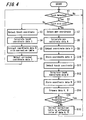
- Step S1 it is determined whether the touch panel 1 or the electromagnetic induction sensor 2 is touched. If there is no touch (NO), then the step S1 is repeated. If the touch is detected (YES), then it is determined whether the touch is carried out with a position indicator (pen) having an incorporated resonant circuit (Step S2).
- Step S2 if a pen is not used (NO), then the coordinate of touch is detected (Step S3) and touch-coordinate data B is then calculated (Step S4). Further, calculated coordinate data B is corrected using the correction table (Step S5) and the corrected coordinate data B is then output (Step S6).
- Step S3 if a pen is not used (NO), then the coordinate of touch is detected (Step S3) and touch-coordinate data B is then calculated (Step S4). Further, calculated coordinate data B is corrected using the correction table (Step S5) and the corrected coordinate data B is then output (Step S6).
- Step S7 the coordinate of the pen is detected at first (Step S7) and the pen coordinate data A is then calculated (Step S8). Further, the coordinate data A is output (Step S9) and the coordinate data A is then stored (Step S10).
- Step S7 the coordinate of the pen is detected at first (Step S7) and the pen coordinate data A is then calculated (Step S8). Further, the coordinate data A is output (Step S9) and the coordinate data A is then stored (Step S10).
- Step S10 the coordinate of the touch is detected (Step S11) and the touch coordinate data B is then calculated (Step S12). Further, the calculated coordinate data B is stored (Step S13) and then the stored coordinate data A, B are compared (Step S14). If the difference between the data A and B is within an allowable range (YES), then the process returns to Step S1.
- Step S14 if the difference between the data A, B is out of the allowable range (NO) in Step S14, then the correction table is revised using the difference value between the data A, B (Step S16). Then, the process returns to Step S1.
- the correction table stores the difference value and correction is then carried out by adding the difference value to the coordinate value detected by the touch sensor or by subtracting the difference value from the coordinate value detected by the touch sensor, then the subsequent output of the touch sensor can be corrected accordingly.
- the correction table is immediately rewritten when the difference between the data A, B exceeds the acceptable range.
- the difference table 16 is provided together with a timer 19 and an instruction discriminating unit 20 for the user.
- the correction table 17 is rewritten after a predetermined time having passed from the last rewrite or in accordance with the user's instruction of rewrite.
- FIGS. 5A and 5B respectively illustrate such procedures.
- Step S21 when the processing is started, it is determined whether a predetermined time has passed after the last rewrite of the correction table or the user issues an instruction of rewriting the correction table (Step S21). Here, if the predetermined time has not passed or there is no instruction by the user (NO), then Step S21 is repeated. On the other hand, if it is detected that the time has passed or there is an instruction by the user (YES), then a correction value is calculated using the data stored in the difference table (Step S22) and the correction table is then overwritten with the calculated correction value (Step S23).
- Step S31 when the processing is started, it is determined whether a predetermined time has passed or the user issues an instruction in a manner similar to the determination in Step S21 (Step S31). Here, if the time has not passed or there is no instruction by the user (NO), then Step S31 is repeated. On the other hand, if it is detected that the time has passed or there is an instruction by the user (YES), then it is determined whether the data stored in the difference table is overall data (Step S32).
- Step S34 If the data stored in the difference table is the overall data in Step S32 (YES), the correction data stored in the difference table overwrites the correction table (Step S33). On the other hand, if the data stored in the difference table is not overall (NO), then a request for overall input with the touch panel and the electromagnetic induction sensor is displayed (Step S34).
- Step S35 it is determined whether the overall input to the touch panel and the electromagnetic sensor is completed in response to the display. If it is not completed (NO) then Step S34 is repeated. If it is completed (YES), then the correction table is overwritten with the correction value stored in the difference table in Step S33. In this way, the correction table 17 is rewritten after a predetermined time has passed from the last rewrite of the correction table or according to the instruction of rewrite from the user.
- an input value from an input device can be carried out automatically or semi-automatically using a simplified method.
- the CPU 5 for the coordinate calculation is provided together with the touch panel 1 and the electromagnetic sensor 2.
- the coordinate input device may be configured such that output signals from the touch panel 1 and the electromagnetic sensor 2 can be directly input into a personal computer (not shown) and the CUP 5 for the coordinate calculation can be provided as a driver incorporated in the personal computer.
- the difference value is stored as correction information in the difference table 16 in accordance with the coordinate value from the coordinate calculation unit 11.
- parameter values of an arithmetic expression for the correction at the correction processing unit 12 may be stored in advance.
Description
- The present invention relates to a coordinate input device suitable for use in a digitizer connected to a computer or the like.
- For example, a touch panel (pressure-sensitive sensor) corrects an input value and then obtains a corrected value to cope with the deterioration of a resistance film with time or the like (for example, see Japanese Unexamined Patent Application Publication No.
H5-250086 - For example, as shown in
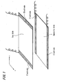
FIG. 1 , a four-wire touch panel has two sides made of any resistance films. One of the sides is provided with electrodes at both ends thereof in the direction of an X-axis and the other of the sides is provided with electrodes at both ends thereof in the direction of a Y-axis. Then, if the surface of the touch panel is pressed, the resistance films on both the sides are caused to contact with each other at a point (position) being pressed, thereby the point being detected. - Specifically, when the resistance films on both the sides contact with each other as described above, a predetermined voltage is applied between the electrodes at the both ends on one of the sides for a period in the contact state so as to detect a voltage between both the electrodes on the other side. In the subsequent period, a predetermined voltage is applied between the electrodes at the both ends on the other side so as to detect a voltage between both the electrodes on one side. From these detected voltages, an X-Y coordinate can be detected.
- However, such configuration of the touch panel may cause variations of resistance value of a resistance film and correction may be then required for obtaining an input value. In addition, when using a touch panel in a typical method, input points being pressed tend to be unevenly distributed. Therefore, such aged deterioration as a resistance film being broken in the vicinity of the input points, may tend to occur. Hence, an input value is corrected to cope with the aging or the like of a resistance film, as disclosed in Japanese Unexamined Patent Application Publication No.
H5-250086 - However, complicated signal processing may be required for such correction, so that the user should carry out a calibration operation. Therefore, a user in general may not carry out any calibration operation even if an error occurs in an input coordinate.
- In contrast, for a five-wire or eight-wire coordinate input device, for example, a touch panel for automatically correcting an input coordinate by the device itself has been proposed. In this case, however, the configuration of the device and the production process thereof may become complicated because of an increase in the number of wires. Further, for correcting such input coordinate by the device itself, a complicated computing and so on may be required. Therefore, it has been also pointed out to be difficult in practice.
- On the other hand, an input device, such as an electromagnetic induction sensor, which may not require any particular correction for obtaining an input value, has also been proposed (see, for example, Japanese Unexamined Patent Application Publication No.
H5-298007 - As shown in
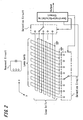
FIG. 2 , for example, the electromagnetic sensor includes a plurality of loop coils being arranged in X and Y directions. When a position indicator approaches any of these loop coils, a resonant circuit incorporated in the position indicator resonates to compute an X-Y coordinate based on a resonance signal and the selected position of the loop coil. Consequently, a detailed input value (coordinate) without a need of correction can be obtained. However, for an input with such an electromagnetic induction system, a specific position indicator may be required. Thus, the input may not be carried out readily at any time. - Accordingly, another coordinate input device has been studied in which these sensors are combined and integrated to enable a variety of positional indication to be obtained.
- However, even in the case of combining and integrating two different input devices, some of the aforementioned problems may remain.
- That is, for example, when a touch panel (pressure-sensitive sensor) is used as a first input device, there may be a need of an input correction to cope with the deterioration of a resistance film with time. In that case, complicated signal processing, a calibration operation by a user, and so on may be required. On the other hand, for example, when an electromagnetic induction sensor is used as a second input device, correction may not be required upon obtaining an input value. However, when the electromagnetic induction sensor is used, a specific position indicator may be required and the input may not be carried out readily at any time.
-
US 2004/0104899 A1 discloses a touch panel for a display device with integrated functionality provided by resistive-type and EM-type touch panels. The touch panel is integrated with the display device and includes a resistive-type touch panel arranged above the display device and an EM-type touch panel arranged below the display device. - The invention provides a coordinate input apparatus, a method for determining correction information for correcting an input value, and a computer program product as defined in the independent claims. Further embodiments are described in the dependent claims.
- According to an embodiment of the present invention, there is provided a coordinate input device including a first input device obtaining coordinate data as a first input value said first input device requiring an input-value correction and a second input device obtaining said coordinate data as a second input value, said second input device not requiring an input-value correction. The coordinate input device includes a determining unit configured to determine that the first input device and the second input device simultaneously obtain the first input value and the second input value, respectively. The coordinate input device also includes a storing unit configured to store a relationship between the simultaneously obtained first input value from the first input device and second input value from the second input device as correction information. The coordinate input device further includes a correcting unit configured to correct coordinate data corresponding to the first input value on the basis of the correction information.
- According to an embodiment of the coordinate input device, the second input value from the second input device is the correction information for the first input value from the first input device.
- According to an embodiment of the coordinate input device, the correction information is a parameter value when the first input value is calculated from a value obtained from the first input device.
- According to an embodiment of the coordinate input device, the correction information is a difference value between the first input value from the first input device and the second input value from the second input device.
- An embodiment of the coordinate input device further includes a position indicator capable of simultaneous input, in which instructions to input the first input value and the second input value indicated by the position indicator within a range corresponding to predetermined areas or whole areas of the first input device and the second input device are displayed on the first input device and the second input device.
- An embodiment of the coordinate input device further includes a display device laid on the first input device and the second input device and the predetermined areas are displayed on the display device.
- According to an embodiment of the coordinate input device, the correction information at the time of simultaneously obtaining the first input value and the second input value is stored as a correction table for each coordinate of the first input value.
- According to an embodiment of the coordinate input device, the correction table includes a first correction table used for correcting the first input value from the first input device and a second correction table for storing the difference information for each coordinate of the first input value. The information stored in the second correction table is overwritten on the first correction table at a given timing.
- According to an embodiment of the coordinate input device, the parameter value includes a first parameter value used for correcting the first input value from the first input device and a second parameter value stored each time the first input device and the second input device simultaneously obtain the first input value and the second input value. The second parameter value is overwritten on the first parameter value at a given timing.
- According to an embodiment of the coordinate input device, the given timing is extracted by detecting a timing with an incorporated clock or an instruction of a user or a system startup.
- According to an embodiment of the coordinate input device, the first input device is a pressure-sensitive sensor and the second input device is an electromagnetic-induction sensor.
- According to an embodiment of the coordinate input device, the first input value is detected by the pressure-sensitive sensor simultaneously with a detection of the second input value by the electromagnetic-induction sensor. An output of the electromagnetic-induction sensor is compared with an output of the pressure-sensitive sensor to obtain the correction information.
- The coordinate input device as described in any of the embodiments has an advantage in that a first input value requiring a correction can be automatically or semi-automatically corrected by a simplified method.
- According to an embodiment of the present invention, there is provided a method for determining correction information for correcting an input value. The input value is input into a coordinate input apparatus. The method comprise obtaining coordinate data as a first input value from a first input device that requires an input-value correction. The coordinate data is obtained as a second input value from a second input device that does not require an input-value correction.
- It is determined that the first input value and the second input value are simultaneously obtained. A relationship between the simultaneously obtained first input value and second input value is stored as correction information, and coordinate data corresponding to the first input value is corrected on the basis of the correction information.
- In another aspect, there is provided a computer program product comprising computer readable instructions to perform a method for determining correction information for correcting an input value. The computer readable instructions may be executed on an input apparatus, or alternatively on a connected computer.
-
- Fig. 1
- is a schematic diagram for illustrating a touch panel.
- Fig. 2
- is a schematic diagram for illustrating an electromagnetic- induction sensor.
- Fig. 3
- is a block diagram illustrating a coordinate input device according to an embodiment of the present invention.
- Fig. 4
- is a flowchart for explaining an operation of the coordinate input device.
- Figs. 5A and 5B
- are flowcharts for explaining the operation of the coordinate input device, where
FIGS. 5A and 5B represent different procedures. - A coordinate input device according to an embodiment of the present invention will be described with reference to
FIGS. 3 to 5 . First,FIG. 3 is a block diagram showing a configuration of the coordinate input device according to the embodiment of the present invention. - As shown in
FIG. 3 , the coordinate input device of the present embodiment includes: a first input device that requires a correction for obtaining an input value, for example a touch panel (pressure-sensitive sensor) 1 as disclosed in Japanese Unexamined Patent Application Publication No.H5-250086 electromagnetic induction sensor 2 disclosed in Japanese Unexamined Patent Application Publication No.H5-298007 touch panel 1 and theelectromagnetic induction sensor 2 are stacked together. Thetouch panel 1 may be exposed on the input side. Theelectromagnetic induction sensor 2 may be apart from the input side. In addition, a liquid crystal display or the like may be placed between thetouch panel 1 and theelectromagnetic induction sensor 2. - The
touch panel 1 and theelectromagnetic sensor 2 may be instructed by aposition indicator 3 incorporating a resonant circuit. In this case, both thetouch panel 1 and theelectromagnetic induction sensor 2 can detect an indicated position. However, theelectromagnetic sensor 2 detects a coordinate with accuracy compared with thetouch panel 1. In contrast, when the tip of afinger 4 or the like having no resonant circuit is used to give instructions, an instructed position is only detected on thetouch panel 1 but not on theelectromagnetic sensor 2. - The detection with the
touch panel 1 tends to cause deterioration with time. Thus, an input value supplied from thetouch panel 1 to a central processing unit (CPU) 5 for coordinate calculation is converted into a coordinate at a coordinate calculatingunit 11. Subsequently, the input value is supplied to acorrection processing unit 12 to obtain a correct value. In contrast, an input value obtained by theelectromagnetic induction sensor 2 may not require correction. Thus, an input value supplied to theCPU 5 from theelectromagnetic induction sensor 2 is then supplied to the coordinate calculatingunit 13 and converted into a coordinate with accuracy. - The coordinate calculating
units unit 14 and the time both the inputs are simultaneously carried out is determined. Subsequently, a determining signal is supplied to adifference detecting unit 15 where the difference between coordinates converted from values input to the coordinate calculatingunits unit 11. - Therefore, the difference table 16 stores a difference between the coordinate value calculated at the coordinate calculating
unit 11 and a correct coordinate value calculated for the coordinate value at the coordinate calculatingunit 13. Subsequently, the resulting difference value stored in the difference table 16 is then stored in a correction table 17. In thecorrection processing unit 12, the difference value from the correction table 17 is added to or subtracted from the coordinate value calculated at the coordinate calculatingunit 11. Consequently, a correction procedure can be carried out to correct the coordinate value calculated at the coordinate calculatingunit 11 to be the correct coordinate value calculated at the coordinate calculatingunit 13. - Subsequently, either the coordinate value corrected at the
correction processing unit 12 or the coordinate value calculated at the coordinate calculatingunit 13 is selected by anoutput selecting unit 18 and then output as a coordinateoutput 6. In other words, in theoutput selecting unit 18, the coordinate value calculated at the coordinate calculatingunit 13 is selected when it is obtained. In contrast, the coordinate value corrected at thecorrection processing unit 12 is selected when the coordinate value calculated at the coordinate calculatingunit 13 is not obtained. Consequently, a correct coordinate value is obtained at any time as the coordinateoutput 6 without depending on the use of theposition indicator 3. - As shown in
FIG. 3 , functional blocks of a program executed by theCPU 5 are illustrated within theCPU 5. Next,FIG. 4 shows the steps of the program in flowchart. - As shown in
FIG. 4 , when the processing is started, it is determined whether thetouch panel 1 or theelectromagnetic induction sensor 2 is touched (Step S1). If there is no touch (NO), then the step S1 is repeated. If the touch is detected (YES), then it is determined whether the touch is carried out with a position indicator (pen) having an incorporated resonant circuit (Step S2). - In the step S2, if a pen is not used (NO), then the coordinate of touch is detected (Step S3) and touch-coordinate data B is then calculated (Step S4). Further, calculated coordinate data B is corrected using the correction table (Step S5) and the corrected coordinate data B is then output (Step S6). These steps of the processing may be similar to those carried out on a typical touch panel. Furthermore, after completing these steps, the process returns to Step S1.
- On the other hand, if the pen is used in Step S2 (YES), the coordinate of the pen is detected at first (Step S7) and the pen coordinate data A is then calculated (Step S8). Further, the coordinate data A is output (Step S9) and the coordinate data A is then stored (Step S10). These steps may be the same as those carried out with a typical electromagnetic sensor. In the present embodiment, the following steps are subsequently carried out.
- That is, after Step S10, the coordinate of the touch is detected (Step S11) and the touch coordinate data B is then calculated (Step S12). Further, the calculated coordinate data B is stored (Step S13) and then the stored coordinate data A, B are compared (Step S14). If the difference between the data A and B is within an allowable range (YES), then the process returns to Step S1.
- On the other hand, if the difference between the data A, B is out of the allowable range (NO) in Step S14, then the correction table is revised using the difference value between the data A, B (Step S16). Then, the process returns to Step S1. Here, if the correction table stores the difference value and correction is then carried out by adding the difference value to the coordinate value detected by the touch sensor or by subtracting the difference value from the coordinate value detected by the touch sensor, then the subsequent output of the touch sensor can be corrected accordingly.
- As indicated in the embodiment illustrated in
FIG. 4 , the correction table is immediately rewritten when the difference between the data A, B exceeds the acceptable range. However, a frequent rewrite of the memory may be undesirable. Accordingly, in the embodiment illustrated inFIG. 3 , the difference table 16 is provided together with atimer 19 and aninstruction discriminating unit 20 for the user. The correction table 17 is rewritten after a predetermined time having passed from the last rewrite or in accordance with the user's instruction of rewrite.FIGS. 5A and 5B respectively illustrate such procedures. - Specifically, in the flowchart shown in
FIG. 5A , when the processing is started, it is determined whether a predetermined time has passed after the last rewrite of the correction table or the user issues an instruction of rewriting the correction table (Step S21). Here, if the predetermined time has not passed or there is no instruction by the user (NO), then Step S21 is repeated. On the other hand, if it is detected that the time has passed or there is an instruction by the user (YES), then a correction value is calculated using the data stored in the difference table (Step S22) and the correction table is then overwritten with the calculated correction value (Step S23). - In the flowchart illustrated in
FIG. 5B , when the processing is started, it is determined whether a predetermined time has passed or the user issues an instruction in a manner similar to the determination in Step S21 (Step S31). Here, if the time has not passed or there is no instruction by the user (NO), then Step S31 is repeated. On the other hand, if it is detected that the time has passed or there is an instruction by the user (YES), then it is determined whether the data stored in the difference table is overall data (Step S32). - If the data stored in the difference table is the overall data in Step S32 (YES), the correction data stored in the difference table overwrites the correction table (Step S33). On the other hand, if the data stored in the difference table is not overall (NO), then a request for overall input with the touch panel and the electromagnetic induction sensor is displayed (Step S34).
- Subsequently, it is determined whether the overall input to the touch panel and the electromagnetic sensor is completed in response to the display (Step S35). If it is not completed (NO) then Step S34 is repeated. If it is completed (YES), then the correction table is overwritten with the correction value stored in the difference table in Step S33. In this way, the correction table 17 is rewritten after a predetermined time has passed from the last rewrite of the correction table or according to the instruction of rewrite from the user.
- As described above, according to the coordinate input device of the embodiment, an input value from an input device, which may require correction, can be carried out automatically or semi-automatically using a simplified method.
- In the above-described embodiment, the
CPU 5 for the coordinate calculation is provided together with thetouch panel 1 and theelectromagnetic sensor 2. Alternatively, the coordinate input device may be configured such that output signals from thetouch panel 1 and theelectromagnetic sensor 2 can be directly input into a personal computer (not shown) and theCUP 5 for the coordinate calculation can be provided as a driver incorporated in the personal computer. - Furthermore, in the above-described embodiment, the difference value is stored as correction information in the difference table 16 in accordance with the coordinate value from the coordinate
calculation unit 11. Alternatively, for example, parameter values of an arithmetic expression for the correction at thecorrection processing unit 12 may be stored in advance. - An example of such parameter values will be described below.
- If true coordinate values (values obtained from the
electromagnetic induction sensor 2 in the present embodiment) are (EX1, EY1), (EX2, EY2) and coordinate values to be corrected (values obtained from thetouch panel 1 in the present embodiment) are (RX1, RY1), (RX2, RY2), then correction parameters in the X axis and the Y axis are as follows: - INCL X = (EX2-EX1)/(RX2-RX1)
- INCL Y = (EY2-EY1)/(RY2-RY1)
- Storing such parameter values (INCL X) (INCL Y) allows the collection of the coordinate value with the
touch panel 1. Consequently, the characteristic feature of the coordinate input device according to an embodiment of the present invention is obtained such that the correction information is a parameter value used in calculation of a first input value from a value obtained from the first input device. - Furthermore, the characteristic feature of the coordinate input device according to an embodiment of the present invention is as follows. The parameter values include a first parameter value to be used in correction of a first input value from the first input device and a second parameter value stored each time the first input device and the second input device simultaneously obtain a first input value and a second input value. The second parameter is overwritten on the first parameter value at a given timing.
- Furthermore, it will be appreciated that the present invention is not limited to the above embodiment and various modification examples and application examples may be made thereto without departing the gist of the present invention written in the scope of claims.
Claims (19)
- A coordinate input apparatus (5)comprising:- a first input device (1) for obtaining coordinate data as a first input value, said first input device requiring an input-value correction;- a second input device (2) for obtaining said coordinate data as a second input value, said second input device not requiring an input-value correction;characterized by- a determining unit (14) configured to determine that the first input device and the second input device simultaneously obtain the first input value and the second input value, respectively;- a storing unit (16, 17) configured to store a relationship between the simultaneously obtained first input value from the first input device and second input value from the second input device as correction information; and- a correcting unit (12) configured to correct coordinate data corresponding to the first input value on the basis of the correction information.
- A coordinate input apparatus according to claim 1, wherein
the second input value from the second input device is the correction information for the first input value from the first input device. - A coordinate input apparatus according to claim 1, wherein
the correction information is a parameter value determined when the first input value is calculated from a value obtained from the first input device. - A coordinate input apparatus according to claim 1, wherein
the correction information is a difference value between the first input value from the first input device and the second input value from the second input device. - A coordinate input apparatus according to claim 1, further comprising a position indicator capable of simultaneous input, wherein
instructions to input the first input value and the second input value indicated by the position indicator within a range corresponding to predetermined areas or whole areas of the first input device and the second input device are displayed on the first input device and the second input device. - A coordinate input apparatus according to claim 5, further comprising a display device laid on the first input device and the second input device, wherein
the predetermined areas are displayed on the display device. - A coordinate input apparatus according to claim 1, wherein
the correction information at the time of simultaneously obtaining the first input value and the second input value is stored as a correction table (16, 17) for each coordinate of the first input value. - A coordinate input apparatus according to claim 7,
wherein the correction table includes a first correction table (17) used for correcting the first input value from the first input device and a second correction table (16) for storing the difference information for each coordinate of the first input value, and
wherein the information stored in the second correction table is overwritten on the first correction table at a given timing. - A coordinate input apparatus according to claim 3, wherein
the parameter value includes a first parameter value used for correcting the first input value from the first input device and a second parameter value stored each time the first input device and the second input device simultaneously obtain the first input value and the second input value, and
wherein the second parameter value is overwritten on the first parameter value at a given timing. - A coordinate input apparatus according to claim 8, wherein
the given timing is extracted by detecting a timing with an incorporated clock (19) or an instruction of a user or a system startup. - A coordinate input apparatus according to claim 1,
wherein the first input device is a pressure-sensitive sensor and the second input device is an electromagnetic-induction sensor. - A coordinate input apparatus according to claim 11, wherein
the first input value is detected by the pressure-sensitive sensor simultaneously with a detection of the second input value by the electromagnetic-induction sensor, and
an output of the electromagnetic-induction sensor is compared with an output of the pressure-sensitive sensor to obtain the correction information. - A method for determining correction information for correcting an input value, the input value being input into a coordinate input apparatus, the method comprising:- obtaining coordinate data as a first input value from a first input device that requires an input-value correction (S11);- obtaining said coordinate data as a second input value from a second input device that does not require an input-value correction (S7);characterized by- determining that the first input value and the second input value are simultaneously obtained (S1, S2);- storing a relationship between the simultaneously obtained first input value and second input value as correction information (S16); and- correcting coordinate data corresponding to the first input value on the basis of the correction information (S5).
- The method of claim 13, wherein the second input value is the correction information for the first input value.
- The method of claim 13, wherein the correction information is a difference value between the first input value and the second input value.
- The method of claim 13, wherein the correction information at the time of simultaneously obtaining the first input value and the second input value is stored as a correction table for each coordinate of the first input value.
- The method of claim 16, wherein the correction table includes a first correction table used for correcting the first input value from the first input device and a second correction table for storing the difference information for each coordinate of the first input value, and
the method further comprises overwriting the information stored in the second correction table on the first correction table at a given timing. - The method of claim 17, further comprising extracting the given timing by detecting timing with an incorporated clock or an instruction of a user or a system startup.
- A computer program product comprising computer readable instructions to perform a method in accordance with any one of claims 13 to 18.
Applications Claiming Priority (1)
| Application Number | Priority Date | Filing Date | Title |
|---|---|---|---|
| JP2006336029A JP4966636B2 (en) | 2006-12-13 | 2006-12-13 | Coordinate input device |
Publications (3)
| Publication Number | Publication Date |
|---|---|
| EP1933228A2 EP1933228A2 (en) | 2008-06-18 |
| EP1933228A3 EP1933228A3 (en) | 2008-08-20 |
| EP1933228B1 true EP1933228B1 (en) | 2010-08-11 |
Family
ID=39157217
Family Applications (1)
| Application Number | Title | Priority Date | Filing Date |
|---|---|---|---|
| EP07122569A Expired - Fee Related EP1933228B1 (en) | 2006-12-13 | 2007-12-07 | Coordinate input apparatus |
Country Status (6)
| Country | Link |
|---|---|
| US (1) | US8587527B2 (en) |
| EP (1) | EP1933228B1 (en) |
| JP (1) | JP4966636B2 (en) |
| CN (1) | CN101201713B (en) |
| DE (1) | DE602007008347D1 (en) |
| TW (1) | TWI442300B (en) |
Families Citing this family (37)
| Publication number | Priority date | Publication date | Assignee | Title |
|---|---|---|---|---|
| JP2008225980A (en) * | 2007-03-14 | 2008-09-25 | Young Fast Optoelectronics Co Ltd | Composite touch sensor |
| US8928595B2 (en) * | 2008-06-24 | 2015-01-06 | Microsoft Corporation | Touch screen calibration sensor |
| JP5806799B2 (en) * | 2009-01-26 | 2015-11-10 | 任天堂株式会社 | Information processing apparatus, information processing program, information processing system, and information processing method |
| GB2475928A (en) * | 2009-12-23 | 2011-06-08 | Promethean Ltd | An input system including an interactive surface for detecting a contact point and the presence of a response to an excitation signal |
| TWI526912B (en) * | 2010-03-16 | 2016-03-21 | 元太科技工業股份有限公司 | Electromagnetic touch displayer |
| JP2011210188A (en) * | 2010-03-30 | 2011-10-20 | Sony Corp | Image processing apparatus, method of displaying image, image display program, and recording medium having image display program recorded thereon |
| US9041649B2 (en) * | 2010-05-18 | 2015-05-26 | Panasonic Intellectual Property Corportion of America | Coordinate determination apparatus, coordinate determination method, and coordinate determination program |
| JP5498583B2 (en) * | 2010-10-27 | 2014-05-21 | アルプス電気株式会社 | Input device and display device |
| US9310923B2 (en) | 2010-12-03 | 2016-04-12 | Apple Inc. | Input device for touch sensitive devices |
| CN102129324B (en) * | 2011-03-17 | 2012-05-02 | 汉王科技股份有限公司 | Touch control device, control method thereof and electronic equipment with touch control device |
| TWI453649B (en) * | 2011-05-02 | 2014-09-21 | Shih Hua Technology Ltd | Display device with touch panel |
| TWI454978B (en) * | 2011-05-02 | 2014-10-01 | Shih Hua Technology Ltd | Touching based input device |
| TW201250530A (en) * | 2011-06-07 | 2012-12-16 | Hannstar Display Corp | Integrated touch panel structure and manufacturing method thereof |
| US9329703B2 (en) | 2011-06-22 | 2016-05-03 | Apple Inc. | Intelligent stylus |
| US8928635B2 (en) | 2011-06-22 | 2015-01-06 | Apple Inc. | Active stylus |
| CN103257758A (en) * | 2012-02-17 | 2013-08-21 | 林志忠 | Touch device |
| TWI498778B (en) * | 2012-03-19 | 2015-09-01 | Wistron Corp | Method for syncing different touching systems |
| CN103425377B (en) * | 2012-05-21 | 2016-05-25 | 汉王科技股份有限公司 | Coordinates compensation method and device, electromagnetism contactor control device |
| JP5910345B2 (en) | 2012-06-21 | 2016-04-27 | 富士通株式会社 | Character input program, information processing apparatus, and character input method |
| US9652090B2 (en) | 2012-07-27 | 2017-05-16 | Apple Inc. | Device for digital communication through capacitive coupling |
| US9557845B2 (en) * | 2012-07-27 | 2017-01-31 | Apple Inc. | Input device for and method of communication with capacitive devices through frequency variation |
| KR101970971B1 (en) * | 2012-08-01 | 2019-04-22 | 삼성전자주식회사 | Method for compensating of the position error in pressure type touch screen, machine-readable storage medium and portable terminal |
| KR101995403B1 (en) * | 2012-09-14 | 2019-07-02 | 삼성전자 주식회사 | Stylus pen, electroinic device and method for processing input using it |
| CN102880357B (en) * | 2012-09-19 | 2015-09-23 | 广州视睿电子科技有限公司 | Touch control device coordinate calibration method and device |
| CN102929411B (en) * | 2012-10-15 | 2015-09-23 | 贺爱兰 | Electromagnetic touch device |
| US20140204038A1 (en) * | 2013-01-21 | 2014-07-24 | Kabushiki Kaisha Toshiba | Information apparatus and information processing method |
| US9430061B2 (en) * | 2013-03-07 | 2016-08-30 | Qualcomm Incorporated | Ultrasonic hybrid input device and corresponding tuning method |
| US10048775B2 (en) | 2013-03-14 | 2018-08-14 | Apple Inc. | Stylus detection and demodulation |
| JP2014235612A (en) * | 2013-06-03 | 2014-12-15 | 富士通株式会社 | Terminal device, correction method, and correction program |
| US10845901B2 (en) | 2013-07-31 | 2020-11-24 | Apple Inc. | Touch controller architecture |
| JP2015088032A (en) * | 2013-10-31 | 2015-05-07 | コニカミノルタ株式会社 | Input device, input value correction method, and program |
| CN103713795B (en) * | 2013-12-20 | 2016-06-15 | 深圳市英威腾电气股份有限公司 | A kind of Automatic error correction method for resistive touch screen |
| JP6271732B2 (en) * | 2014-07-07 | 2018-01-31 | シャープ株式会社 | Capacitance value distribution detection circuit, touch panel system, and electronic device |
| US10061450B2 (en) | 2014-12-04 | 2018-08-28 | Apple Inc. | Coarse scan and targeted active mode scan for touch |
| DE102014225235A1 (en) * | 2014-12-09 | 2016-06-09 | Siemens Healthcare Gmbh | Circuit arrangement with a resistive touch screen, medical imaging device with a resistive touch screen and method for operating a resistive touch screen |
| US9720546B2 (en) * | 2015-09-15 | 2017-08-01 | Microsoft Technology Licensing, Llc | Calibration of a force sensitive device |
| US10474277B2 (en) | 2016-05-31 | 2019-11-12 | Apple Inc. | Position-based stylus communication |
Family Cites Families (25)
| Publication number | Priority date | Publication date | Assignee | Title |
|---|---|---|---|---|
| JPS6174025A (en) * | 1984-09-19 | 1986-04-16 | Toshiba Corp | Display device |
| JPS63298427A (en) * | 1987-05-28 | 1988-12-06 | Matsushita Electric Ind Co Ltd | Input device |
| JP2600347B2 (en) * | 1988-11-19 | 1997-04-16 | 富士ゼロックス株式会社 | Input display integrated device |
| EP0421025B1 (en) * | 1989-10-02 | 1999-05-06 | Koninklijke Philips Electronics N.V. | Data processing system with a touch screen and a digitizing tablet, both integrated in an input device |
| US5402151A (en) * | 1989-10-02 | 1995-03-28 | U.S. Philips Corporation | Data processing system with a touch screen and a digitizing tablet, both integrated in an input device |
| JPH04127315A (en) * | 1990-09-19 | 1992-04-28 | Fujitsu Ltd | Personal computer |
| JPH05250086A (en) | 1991-03-29 | 1993-09-28 | Nippon Business Syst Kk | Coordinate input device of resistance film system and its production |
| JP3078391B2 (en) | 1992-04-22 | 2000-08-21 | 株式会社ワコム | Position detection device |
| BE1007462A3 (en) * | 1993-08-26 | 1995-07-04 | Philips Electronics Nv | Data processing device with touch sensor and power. |
| KR100300397B1 (en) * | 1994-04-21 | 2001-10-22 | 김순택 | System having touch panel and digitizer function and driving method |
| US5956020A (en) * | 1995-07-27 | 1999-09-21 | Microtouch Systems, Inc. | Touchscreen controller with pen and/or finger inputs |
| JPH09190268A (en) * | 1996-01-11 | 1997-07-22 | Canon Inc | Information processor and method for processing information |
| JPH09230989A (en) * | 1996-02-26 | 1997-09-05 | Graphtec Corp | Digitizer |
| JPH1049301A (en) * | 1996-08-01 | 1998-02-20 | Sharp Corp | Coordinate input device |
| JPH10133808A (en) * | 1996-10-31 | 1998-05-22 | Nec Corp | Method for automatically correcting input position for digitizer |
| US6417846B1 (en) * | 2000-02-02 | 2002-07-09 | Lee Si-Ken | Multifunction input device |
| JP3988476B2 (en) * | 2001-03-23 | 2007-10-10 | セイコーエプソン株式会社 | Coordinate input device and display device |
| US6762752B2 (en) * | 2001-11-29 | 2004-07-13 | N-Trig Ltd. | Dual function input device and method |
| JP3821002B2 (en) * | 2002-02-07 | 2006-09-13 | グンゼ株式会社 | Touch panel device |
| KR100480823B1 (en) * | 2002-11-14 | 2005-04-07 | 엘지.필립스 엘시디 주식회사 | touch panel for display device |
| US7372455B2 (en) * | 2003-02-10 | 2008-05-13 | N-Trig Ltd. | Touch detection for a digitizer |
| CN100347660C (en) * | 2003-11-04 | 2007-11-07 | 威达电股份有限公司 | Computer system and method for correcting digital plate without correcting software |
| JP2006085489A (en) * | 2004-09-16 | 2006-03-30 | Canon Inc | Coordinate detecting device |
| JP2006336029A (en) | 2005-05-31 | 2006-12-14 | Fts Corporation:Kk | Continuous sputtering apparatus and continuous sputtering method |
| US9019209B2 (en) * | 2005-06-08 | 2015-04-28 | 3M Innovative Properties Company | Touch location determination involving multiple touch location processes |
-
2006
- 2006-12-13 JP JP2006336029A patent/JP4966636B2/en not_active Expired - Fee Related
-
2007
- 2007-12-06 US US11/951,368 patent/US8587527B2/en active Active
- 2007-12-07 EP EP07122569A patent/EP1933228B1/en not_active Expired - Fee Related
- 2007-12-07 DE DE602007008347T patent/DE602007008347D1/en active Active
- 2007-12-10 TW TW096146984A patent/TWI442300B/en not_active IP Right Cessation
- 2007-12-11 CN CN2007101968537A patent/CN101201713B/en not_active Expired - Fee Related
Also Published As
| Publication number | Publication date |
|---|---|
| US8587527B2 (en) | 2013-11-19 |
| JP4966636B2 (en) | 2012-07-04 |
| CN101201713B (en) | 2012-02-01 |
| EP1933228A2 (en) | 2008-06-18 |
| JP2008146580A (en) | 2008-06-26 |
| TWI442300B (en) | 2014-06-21 |
| CN101201713A (en) | 2008-06-18 |
| DE602007008347D1 (en) | 2010-09-23 |
| TW200836094A (en) | 2008-09-01 |
| US20080142280A1 (en) | 2008-06-19 |
| EP1933228A3 (en) | 2008-08-20 |
Similar Documents
| Publication | Publication Date | Title |
|---|---|---|
| EP1933228B1 (en) | Coordinate input apparatus | |
| US9846511B2 (en) | Input device and control method using input device | |
| EP2538307B1 (en) | Electronic terminal, input correction method, and program | |
| US8928609B2 (en) | Combining touch screen and other sensing detections for user interface control | |
| EP2287709A1 (en) | Auto-aligning touch system and method | |
| JPWO2008108275A1 (en) | Display terminal device with touch panel function and calibration method | |
| US20050237310A1 (en) | User interface | |
| US9395853B2 (en) | Reducing common mode noise in touch applications | |
| KR20130073621A (en) | Method for controlling flexible display in portable terminal and apparatus thereof | |
| CN105866781B (en) | Data processing method and electronic equipment | |
| US9552111B2 (en) | Touch sensing device and method of identifying a touched position | |
| TW201349067A (en) | Touch sensor system | |
| US11243639B2 (en) | Touch detection method, touch detection apparatus, and touch sensor controller | |
| CN108759892A (en) | Sensor calibrating method, electronic device and computer readable storage medium | |
| US9244567B2 (en) | Electronic apparatus, calibration method and storage medium | |
| US20120262193A1 (en) | Waveform dividing method for a capacitive touch control device | |
| US20150363043A1 (en) | Touch panel device and touch panel device control method | |
| JP5487350B1 (en) | Touch input device, input detection method, and computer program | |
| US20130241848A1 (en) | Input control device, computer-readable recording medium, and input control method | |
| US20160054848A1 (en) | Display controlling device and electronic apparatus | |
| US9454233B2 (en) | Non-transitory computer readable medium | |
| CN112148139B (en) | Gesture recognition method and computer readable storage medium | |
| JP2008515036A5 (en) | ||
| CN110554812B (en) | Sensing method and sensing module of touch control identification device | |
| JP2013016114A (en) | Touch position detection device for touch panel display |
Legal Events
| Date | Code | Title | Description |
|---|---|---|---|
| PUAI | Public reference made under article 153(3) epc to a published international application that has entered the european phase |
Free format text: ORIGINAL CODE: 0009012 |
|
| AK | Designated contracting states |
Kind code of ref document: A2 Designated state(s): AT BE BG CH CY CZ DE DK EE ES FI FR GB GR HU IE IS IT LI LT LU LV MC MT NL PL PT RO SE SI SK TR |
|
| AX | Request for extension of the european patent |
Extension state: AL BA HR MK RS |
|
| PUAL | Search report despatched |
Free format text: ORIGINAL CODE: 0009013 |
|
| AK | Designated contracting states |
Kind code of ref document: A3 Designated state(s): AT BE BG CH CY CZ DE DK EE ES FI FR GB GR HU IE IS IT LI LT LU LV MC MT NL PL PT RO SE SI SK TR |
|
| AX | Request for extension of the european patent |
Extension state: AL BA HR MK RS |
|
| 17P | Request for examination filed |
Effective date: 20090220 |
|
| 17Q | First examination report despatched |
Effective date: 20090318 |
|
| AKX | Designation fees paid |
Designated state(s): DE FR GB |
|
| GRAP | Despatch of communication of intention to grant a patent |
Free format text: ORIGINAL CODE: EPIDOSNIGR1 |
|
| GRAS | Grant fee paid |
Free format text: ORIGINAL CODE: EPIDOSNIGR3 |
|
| GRAA | (expected) grant |
Free format text: ORIGINAL CODE: 0009210 |
|
| AK | Designated contracting states |
Kind code of ref document: B1 Designated state(s): DE FR GB |
|
| REG | Reference to a national code |
Ref country code: GB Ref legal event code: FG4D |
|
| REF | Corresponds to: |
Ref document number: 602007008347 Country of ref document: DE Date of ref document: 20100923 Kind code of ref document: P |
|
| PLBE | No opposition filed within time limit |
Free format text: ORIGINAL CODE: 0009261 |
|
| STAA | Information on the status of an ep patent application or granted ep patent |
Free format text: STATUS: NO OPPOSITION FILED WITHIN TIME LIMIT |
|
| 26N | No opposition filed |
Effective date: 20110512 |
|
| REG | Reference to a national code |
Ref country code: DE Ref legal event code: R097 Ref document number: 602007008347 Country of ref document: DE Effective date: 20110512 |
|
| REG | Reference to a national code |
Ref country code: FR Ref legal event code: ST Effective date: 20110831 |
|
| PG25 | Lapsed in a contracting state [announced via postgrant information from national office to epo] |
Ref country code: FR Free format text: LAPSE BECAUSE OF NON-PAYMENT OF DUE FEES Effective date: 20110103 |
|
| PGFP | Annual fee paid to national office [announced via postgrant information from national office to epo] |
Ref country code: DE Payment date: 20131220 Year of fee payment: 7 Ref country code: GB Payment date: 20131219 Year of fee payment: 7 |
|
| REG | Reference to a national code |
Ref country code: DE Ref legal event code: R119 Ref document number: 602007008347 Country of ref document: DE |
|
| GBPC | Gb: european patent ceased through non-payment of renewal fee |
Effective date: 20141207 |
|
| PG25 | Lapsed in a contracting state [announced via postgrant information from national office to epo] |
Ref country code: DE Free format text: LAPSE BECAUSE OF NON-PAYMENT OF DUE FEES Effective date: 20150701 Ref country code: GB Free format text: LAPSE BECAUSE OF NON-PAYMENT OF DUE FEES Effective date: 20141207 |