EP1932796A1 - Door device for elevator - Google Patents
Door device for elevator Download PDFInfo
- Publication number
- EP1932796A1 EP1932796A1 EP05790456A EP05790456A EP1932796A1 EP 1932796 A1 EP1932796 A1 EP 1932796A1 EP 05790456 A EP05790456 A EP 05790456A EP 05790456 A EP05790456 A EP 05790456A EP 1932796 A1 EP1932796 A1 EP 1932796A1
- Authority
- EP
- European Patent Office
- Prior art keywords
- door
- car
- car door
- doorway
- sill
- Prior art date
- Legal status (The legal status is an assumption and is not a legal conclusion. Google has not performed a legal analysis and makes no representation as to the accuracy of the status listed.)
- Withdrawn
Links
Images



Classifications
-
- B—PERFORMING OPERATIONS; TRANSPORTING
- B66—HOISTING; LIFTING; HAULING
- B66B—ELEVATORS; ESCALATORS OR MOVING WALKWAYS
- B66B13/00—Doors, gates, or other apparatus controlling access to, or exit from, cages or lift well landings
- B66B13/30—Constructional features of doors or gates
- B66B13/301—Details of door sills
-
- B—PERFORMING OPERATIONS; TRANSPORTING
- B66—HOISTING; LIFTING; HAULING
- B66B—ELEVATORS; ESCALATORS OR MOVING WALKWAYS
- B66B13/00—Doors, gates, or other apparatus controlling access to, or exit from, cages or lift well landings
- B66B13/24—Safety devices in passenger lifts, not otherwise provided for, for preventing trapping of passengers
- B66B13/26—Safety devices in passenger lifts, not otherwise provided for, for preventing trapping of passengers between closing doors
Definitions
- the present invention relates to a door device for an elevator for opening/closing a doorway through which an interior of a car of the elevator communicates with a landing.
- an actuating strip displaceable with respect to each of the doors is provided at an end of the door on a door-closing side thereof.
- the actuating strip moves together with the door while protruding from the end of the door on the door-closing side thereof.
- a sill extending in a moving direction of the door is provided therebelow.
- the sill is provided with a guide groove in which a lower end of the actuating strip is inserted.
- Patent Document 1 JP 05-301692 A
- the actuating strip remains protruding from the door during the movement thereof and hence is liable to be hit by, for example, a wagon and damaged.
- the actuating strip increases in rigidity and weight so as to be prevented from being damaged. Accordingly, in a case where the foreign object is a flexible and light thing such as a string, the actuating strip is unlikely to be displaced with respect to the door even when the foreign object comes into contact with the actuating strip. As a result, detection of the foreign object may become impossible.
- the present invention has been made to solve the above-mentionedproblems, and it is therefore an obj ect of the present invention to obtain a door device for an elevator which makes it possible to detect a foreign object more reliably and achieve an improvement in design.
- a door device for an elevator includes: a car door for opening and closing a car doorway; an actuating strip, provided at an end of the car door on a door-closing side of the car door and designed to be displaceable between a protrusion position at which the actuating strip protrudes from a lower end of the car door and a retraction position located above the protrusion position, the actuating strip being displaced to the protrusion position through full closure of the car doorway by the car door and to the retraction position through a movement of the car door in a door-opening direction of the car door; a car sill provided with a sill hole in which the actuating strip displaced to the protrusion position due to a movement of the car door is inserted and from which the actuating strip is released through displacement of the actuating strip to the retraction position, the car sill being provided at a lower portion of the car doorway; a detection switch for detecting whether or not the actuating strip has been
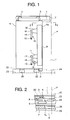
- Fig. 1 is a partially front view showing a door device for an elevator according to Embodiment 1 of the present invention.
- Fig. 2 is a sectional view taken along the line II-II of Fig. 1 .
- Fig. 3 is a partially front view showing the door device for the elevator with a car doorway 1 of Fig. 1 fully closed.
- Fig. 4 is a sectional view taken along the line IV-IV of Fig. 3 .
- the car doorway 1 is half open in Fig. 1 .
- a car of the elevator is provided with the car doorway 1.
- a car-side hanger case 2 fixed to the car is provided at an upper portion of the car doorway 1.
- the car-side hanger case 2 is provided with a car-side door rail 3 extending in the direction of a frontage of the car doorway 1.
- a pair of car doors 4 for opening/closing the car doorway 1 are suspended from the car-side door rail 3.
- a plurality of (two in this example) hanger rollers 5 laid on the car-side door rail 3 are provided at an upper portion of each of the car doors 4.
- Each of the car doors 4 is moved along the car-side door rail 3 due to a driving force of a door driving device (not shown) mounted on the car.
- the respective hanger rollers 5 are rolled on the car-side door rail 3 as the car door 4 is moved.
- a landing doorway 6 ( Figs. 2 and 4 ) is provided at a landing of each floor.
- the car doorway 1 is opposed to the landing doorway 6 when the car is stopped at each floor.
- a landing-side hanger case (not shown) fixed to a wall surface on a landing side is provided at an upper portion of the landing doorway 6.
- the landing-side hanger case is provided with a landing-side door rail (not shown) extending in the direction of a frontage of the landing doorway 6.
- a pair of landing doors 7 ( Figs. 2 and 4 ) for opening/closing the landing doorway 6 are suspended from the landing-side door rail.
- the respective landing doors 7 are movable along the landing-side door rail. Each of the landing doors 7 is moved together with a corresponding one of the car doors 4 while being engaged therewith through an engagement device (not shown) when the car is stopped at each floor.
- the landing doorway 6 is opened/closed as the respective landing doors 7 are moved.
- Door abutment faces 4a which abut on each other when the respective car doors 4 fully close the car doorway 1, are provided at ends of the car doors 4 on door-closing sides thereof, respectively.
- Door abutment faces 7a which abut on each other when the respective landing doors 7 fully close the landing doorway 6, are provided at ends of the landing doors 7 on door-closing sides thereof, respectively.
- a position at which the respective door abutment faces 4a abut on each other and a position at which the respective door abutment faces 7a abut on each other are located on a door abutment reference plane P extending perpendicularly to the direction of the frontages of the car doorway 1 and the landing doorway 6.
- the door abutment reference plane P is located at the centers of the car doorway 1 and the landing doorway 6.
- Each of safety shoes 8 ( Figs. 2 and 4 ) and each of detection plates (actuating strip) 9, which are displaceable with respect to a corresponding one of the car doors 4, are provided at the end of the car door 4 on the door-closing side thereof.
- the safety shoe 8 and the detection plate 9 are disposed between the car door 4 and the landing door 7.
- the detection plate 9 is disposed between the safety shoe 8 and the car door 4.
- the detection plate 9 is lighter in weight than the safety shoe 8.
- the safety shoe 8 and the detection plate 9 are displaced as the car door 4 is moved. That is, a displacement device (not shown) for displacing the safety shoe 8 and the detection plate 9 independently of each other in accordance with the movement of the car door 4 is provided between the car door 4 and the landing door 7.
- the displacement device may be designed, for example, to displace the safety shoe 8 and the detection plate 9 in accordance with the position of the car door 4 with respect to the car, or to displace the safety shoe 8 and the detection plate 9 in accordance with the position of the car door 4 with respect to the landing door 7.
- the safety shoe 8 is moved together with the car door 4 while protruding from the end of the car door 4 on the door-closing side thereof toward the door-closing side.
- each of the safety shoes 8 is accommodated between a corresponding one of the car doors 4 and a corresponding one of the landing doors 7.
- the moving direction of the car door 4 is inverted from the door-closing direction to a door-opening direction thereof through the control performed by a door control device (not shown).
- the detection plate 9 is displaceable between a protrusion position at which the detection plate 9 protrudes downward from a lower end of the car door 4 and a retraction position located above the protrusion position.
- the detection plate 9 protrudes from the end of the car door 4 on the door-closing side thereof in the door-closing direction as well when being located at the protrusion position.
- the detection plate 9 is accommodated between the car door 4 and the landing door 7 when being located at the retraction position.
- the detection plate 9 is displaced toward the protrusion position as the car door 4 is moved in the door-closing direction, and toward the retraction position as the car door 4 is moved in the door-opening direction.
- Each of the detection plates 9 reaches the protrusion position when the car doors 4 fully close the car doorway 1.
- the displacement of each of the detection plates 9 from the retraction position to the protrusion position is started when the car doors 4 reach predetermined positions respectively immediately before fully closing the car doorway 1, and is completed when the car doors 4 fully close the car doorway 1.
- each of the detection plates 9 from the protrusion position to the retraction position is started when the movement of a corresponding one of the car doors 4 in the door-opening direction is started, and is completed when the car door 4 reaches the above-mentioned predetermined position.
- An upper mounting portion 10 is provided on an upper portion of the detection plate 9, and a lower mounting portion 11 is provided on a lower portion of the detection plate 9.
- the upper mounting portion 10 and the lower mounting portion 11 protrude respectively from the detection plate 9 toward a door-opening side.
- the car door 4 is provided with an upper turning shaft 12 and a lower turning shaft 13, which are disposed apart from each other in a height direction of the car door 4.
- the detection plate 9 is supported by the car door 4 via an upper turning link 14 turnable around the upper turning shaft 12 and a lower turning link 15 turnable around the lower turning shaft 13.
- the upper mounting portion 10 is turnably mounted at a tip of the upper turning link 14 by means of a pin 16, and the lower mounting portion 11 is turnably mounted at a tip of the lower turning link 15 by means of a pin 17.
- the detection plate 9 is displaced between the protrusion position and the retraction position through the turning of the upper turning link 14 and the turning of the lower turning link 15.
- the car door 4 is provided with a stopper 18 for holding the detection plate 9 at the protrusion position through abutment on the upper turning link 14.
- the car door 4 is provided with a micro switch (detection switch) 19 for detecting whether or not the detection plate 9 has been displaced to the protrusion position.
- the micro switch 19 detects whether or not the detection plate 9 has been displaced to the protrusion position, depending on a state of establishment of contact with the lower turning link 15.
- the car doorway 1 is provided with a full closure detecting sensor (not shown) for detecting whether or not the car doorway 1 has been fully closed by the car doors 4.
- the door control device controls the movements of the car doors 4 based on the information from the full closure detecting switch and the micro switch 19. That is, the door control device inverts the moving direction of each of the car doors 4 from the door-closing direction to the door-opening direction when the car doors 4 fully close the car doorway 1 and each of the detection plates 9 is off the protrusion position. The door control device allows the car to be moved when the car doors 4 fully close the car doorway 1 and each of the detection plates 9 is at the protrusion position.
- a plurality of door legs 20 are provided at the lower end of the car door 4.
- a protective strip (sweeper) 21 is provided at the lower .end of the car door 4 on the door-closing side thereof.
- the respective door legs 20 and the protective strip 21 protrude downward from the lower end of the car door 4.
- the protective strip 21 protrudes downward by a shorter length than the respective door legs 20.
- a car sill 22 fixed to the car is provided at a lower portion of the car doorway 1.
- the car sill 22 is provided with a car sill groove 23 extending in the direction of the frontage of the car doorway 1, and a sill hole (detection hole) 24 arranged at such a position as to intersect with the door abutment reference plane P.
- the respective door legs 20 and the protective strip 21 are inserted in the car sill groove 23. While remaining inserted in the car sill groove 23, the respective door legs 20 and the protective strip 21 are moved along the car sill groove 23 together with the car door 4.
- the sill hole 24 is a long hole arranged parallel to the direction of the frontage of the car doorway 1 and the direction of the frontage of the landing doorway 6.
- the sill hole 24 is also a through-hole penetrating the car sill 22 vertically.
- a landing sill 25 ( Figs. 2 and 4 ) fixed to the landing is provided at a lower portion of the landing doorway 6.
- the landing sill 25 is provided with a landing sill groove 26 extending in the direction of the frontage of the landing doorway 6.
- a plurality of door legs (not shown) provided at a lower end of each of the landing doors 7 are inserted in the landing sill groove 26. While remaining inserted in the landing sill groove 26, the respective door legs are moved along the landing sill groove 26 together with the landing door 7.
- Fig. 5 is an enlarged sectional view taken along the line V-V of Fig. 4 .
- a lower portion of each of the detection plates 9 is inserted in the sill hole 24 when the car doors 4 fully close the car doorway 1 and each of the detection plates 9 is displaced to the protrusion position.
- the lower portion of the detection plate 9 is released from the sill hole 24 as the detection plate 9 is displaced toward the retraction position.
- Fig. 6 is a front view showing a state in which a string as a foreign object is located on the landing sill 25 and the car sill 22 extending thereacross.
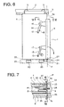
- Fig. 7 is a sectional view taken along the line VII-VII of Fig. 6 .
- Fig. 8 is an enlarged sectional view taken along the line VIII-VIII of Fig. 7 .
- a string (foreign object) 27 is pushed, when being on the car sill 22 extending thereacross, by the protective strip 21 to be conveyed to a position above the sill hole 24 due to the movement of the car door 4 in the door-closing direction.
- the detection plate 9 gets stuck with the string 27 and hence is prevented from being displaced to the protrusion position when the string 27 is above the sill hole 24.
- a dimension D ( Fig. 8 ) of the sill hole 24 in a width direction thereof is adjusted such that a tensile force for supporting the detection plate 9 is applied to the string 27 when the detection plate 9 gets stuck with the string 27.
- the lower portion of the detection plate 9 is inserted in the sill hole 24 when the car doorway 1 and the landing doorway 6 are fully closed.
- the door control device has detected that the lower turning link 15 is in contact with the micro switch 19 and that the detection plate 9 is at the protrusion position.
- each of the car doors 4 is moved in the door-opening direction, so the detection plate 9 is displaced from the protrusion position to the retraction position.
- the lower portion of the detection plate 9 is released from the state of being inserted in the sill hole 24, so the lower turning link 15 moves away from the micro switch 19.
- the car doors 4 are moved while being engaged with the landing doors 7 respectively, so the car doorway 1 and the landing doorway 6 are fully opened.
- each of the car doors 4 is moved in the door-closing direction, so the car doorway 1 is fully closed.
- the detection plate 9 is displaced from the retraction position to the protrusion position as the car door 4 is moved, so the lower portion of the detection plate 9 is inserted into the sill hole 24.
- the door control device detects that the lower turning link 15 is in contact with the micro switch 19 and that the detection plate 9 has reached the protrusion position.
- the door control device detects that the car doors 4 fully close the car doorway 1 and that each of the detection plates 9 has reached the protrusion position, the car is thereby allowed to be moved.
- the door device operates when an elongated foreign object such as the string 27 is on the car sill 22 and the landing sill 25 extending thereacross.
- the string 27 is moved in the door-closing direction together with the car door 4 while being pushed by the protective strip 21.
- the string 27 is conveyed to such a position as to extend above and across the sill hole 24 when the car doors 4 fully close the car doorway 1.
- each of the detection plates 9 is displaced from the retraction position toward the protrusion position immediately before the car doors 4 fully close the car doorway 1.
- the string 27 is above the sill hole 24 extending thereacross, so the lower end of the detection plate 9 gets stuck with the string 27.
- the detection plate 9 is prevented from being displaced to the protrusion position by the string 27.
- each of the car doors 4 is further moved in the door-closing direction with the detection plate 9 remaining stuck with the string 27, so the car doorway 1 is fully closed. That is, the car doorway 1 is fully closed with the lower turning link 15 remaining apart from the micro switch 19.
- the car door 4 is provided with the detection plate 9 displaceable between the protrusion position at which the detection plate 9 protrudes from the lower end of the car door 4 and the retraction position located above the protrusion position, and the car sill 22 is provided with the sill hole 24 into which the lower portion of the detection plate 9 is inserted through displacement of the detection plate 9 to the protrusion position. Therefore, even in a case where an elongated and flexible foreign object such as a string is on the car sill 22 extending thereacross, a tensile force can be applied to the string through interposition thereof between the detection plate 9 and the sill hole 24, so the detection plate 9 can be prevented more reliably frombeing displaced to the protrusion position.
- Each of the detection plates 9 reaches the protrusion position only when the car doors 4 fully close the car doorway 1. It is therefore sufficient to provide the sill hole 24 only in a part of the car sill 22, and there is no need to provide a groove in the car sill 22 over the entire moving range of the car door 4. Accordingly, the door device can be improved in design.
- the sill hole 24 passes through the car sill 22, so the foreign object can be prevented from staying within the sill hole 24. As a result, erroneous detection of the presence of the foreign object can be prevented.
- the detection plate 9 protrudes toward the door-closing side from the end of the car door 4 on the door-closing side thereof as well when being at the protrusion position. Therefore, even in a case where the string 27 extends across a position located apart upward from the car sill 22, the string 27 can come into contact with the detection plate 9 when the car doorway 1 is fully closed. Thus, the detection plate 9 can be displaced with respect to the car door 4, so the string 27 can be detected more reliably.
- the dedicated protective strip 21 is provided at the lower end of the car door 4 to convey the string 27 to the position above the sill hole 24.
- the door legs 20 may be designed to serve as the protective strip 21 as well. This construction makes it possible to dispense with the dedicated protective strip 21 and hence reduce the cost of manufacturing.
- Fig. 9 is a partially sectional view showing a door device for an elevator according to Embodiment 2 of the present invention.
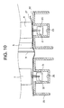
- Fig. 10 is an enlarged sectional view taken along the line X-X of Fig. 9 .
- the lower portion of the detection plate 9 is inserted into a gap between the car sill 22 and the landing sill 25 through displacement of the detection plate 9 to the protrusion position, and is released from the gap between the car sill 22 and the landing sill 25 through displacement of the detection plate 9 to the retraction position.
- Embodiment 2 of the present invention is identical to Embodiment 1 of the present invention in other constructional details.
- the lower portion of the detectionplate 9 is inserted into the gap between the car sill 22 and the landing sill 25 when the detection plate 9 is displaced to the protrusion position, so there is no need to provide the car sill 22 with a sill hole into which the detection plate 9 is inserted.
- the door device can be simplified in structure.
- the present invention is applied to a biparting door device designed such that the car doors 4 and the landing doors 7 separate respectively from each other at the center of the door device to open toward both sides.
- the present invention may also be applied to a single swing door device designed such that the car door 4 and the landing door 7 open respectively only in one direction.
Landscapes
- Elevator Door Apparatuses (AREA)
Abstract
A car doorway is opened/closed by a car door. An actuating strip, displaceable between a protrusion position at which the actuating strip protrudes from a lower end of the car door and a retraction position located above the protrusion position, is provided at an end of the car door on a door-closing side thereof. The actuating strip is displaced to the protrusion position through full closure of the car doorway by the car door, and to the retraction position through a movement of the car door in a door-opening direction thereof. A car sill provided with a sill hole passing therethrough is provided at a lower portion of the car doorway. The actuating strip is inserted, through displacement thereof to the protrusion position due to a movement of the car door, into the sill hole. The actuating strip is released, through displacement thereof to the retraction position, from a state of being inserted in the sill hole. A detection switch detects whether or not the actuating strip has been displaced to the protrusion position. A door control device controls the movement of the car door based on information from the detection switch.
Description
- The present invention relates to a door device for an elevator for opening/closing a doorway through which an interior of a car of the elevator communicates with a landing.
- In a conventional door device for an elevator, with a view to detecting that a foreign object has been sandwiched between a pair of doors, an actuating strip displaceable with respect to each of the doors is provided at an end of the door on a door-closing side thereof. The actuating strip moves together with the door while protruding from the end of the door on the door-closing side thereof. A sill extending in a moving direction of the door is provided therebelow. The sill is provided with a guide groove in which a lower end of the actuating strip is inserted. When the actuating strip comes into contact with the foreign obj ect and then is displaced with respect to the door, the moving direction of the door is inverted from a door-closing direction thereof to a door-opening direction thereof (see Patent Document 1).
- Patent Document 1:
JP 05-301692 A - However, in the conventional door device for the elevator constructed as described above, the actuating strip remains protruding from the door during the movement thereof and hence is liable to be hit by, for example, a wagon and damaged. Thus, the actuating strip increases in rigidity and weight so as to be prevented from being damaged. Accordingly, in a case where the foreign object is a flexible and light thing such as a string, the actuating strip is unlikely to be displaced with respect to the door even when the foreign object comes into contact with the actuating strip. As a result, detection of the foreign object may become impossible.
- Further, the door is moved with the actuating strip inserted in the guide groove, so the sill must be provided with the guide groove over an entire moving range of the door. In consequence, an attempt to make an improvement in design is obstructed.
- The present invention has been made to solve the above-mentionedproblems, and it is therefore an obj ect of the present invention to obtain a door device for an elevator which makes it possible to detect a foreign object more reliably and achieve an improvement in design.
- A door device for an elevator according to the present invention includes: a car door for opening and closing a car doorway; an actuating strip, provided at an end of the car door on a door-closing side of the car door and designed to be displaceable between a protrusion position at which the actuating strip protrudes from a lower end of the car door and a retraction position located above the protrusion position, the actuating strip being displaced to the protrusion position through full closure of the car doorway by the car door and to the retraction position through a movement of the car door in a door-opening direction of the car door; a car sill provided with a sill hole in which the actuating strip displaced to the protrusion position due to a movement of the car door is inserted and from which the actuating strip is released through displacement of the actuating strip to the retraction position, the car sill being provided at a lower portion of the car doorway; a detection switch for detecting whether or not the actuating strip has been displaced to the protrusion position; and a door control device for controlling the movement of the car door based on information from the detection switch.
-
-
Fig. 1 is a partially front view showing a door device for an elevator according to Embodiment 1 of the present invention. -
Fig. 2 is a sectional view taken along the line II-II ofFig. 1 . -
Fig. 3 is a partially front view showing the door device for the elevator with a car doorway ofFig. 1 fully closed. -
Fig. 4 is a sectional view taken along the line IV-IV ofFig. 3 . -
Fig. 5 is an enlarged sectional view taken along the line V-V ofFig. 4 . -
Fig. 6 is a front view showing a state in which a string as a foreign object is located on the landing sill and the car sill extending thereacross. -
Fig. 7 is a sectional view taken along the line VII-VII ofFig. 6 . -
Fig. 8 is an enlarged sectional view taken along the line VIII-VIII ofFig. 7 . -
Fig. 9 is a partially sectional view showing a door device for an elevator according toEmbodiment 2 of the present invention. -
Fig. 10 is an enlarged sectional view taken along the line X-X ofFig. 9 . - Preferred embodiments of the present invention will be described hereinafter with reference to the drawings.
-
Fig. 1 is a partially front view showing a door device for an elevator according to Embodiment 1 of the present invention.Fig. 2 is a sectional view taken along the line II-II ofFig. 1 .Fig. 3 is a partially front view showing the door device for the elevator with a car doorway 1 ofFig. 1 fully closed.Fig. 4 is a sectional view taken along the line IV-IV ofFig. 3 . It should be noted that the car doorway 1 is half open inFig. 1 . Referring toFigs. 1 to 4 , a car of the elevator is provided with the car doorway 1. A car-side hanger case 2 fixed to the car is provided at an upper portion of the car doorway 1. The car-side hanger case 2 is provided with a car-side door rail 3 extending in the direction of a frontage of the car doorway 1. A pair ofcar doors 4 for opening/closing the car doorway 1 are suspended from the car-side door rail 3. - A plurality of (two in this example)
hanger rollers 5 laid on the car-side door rail 3 are provided at an upper portion of each of thecar doors 4. Each of thecar doors 4 is moved along the car-side door rail 3 due to a driving force of a door driving device (not shown) mounted on the car. Therespective hanger rollers 5 are rolled on the car-side door rail 3 as thecar door 4 is moved. - A landing doorway 6 (
Figs. 2 and4 ) is provided at a landing of each floor. The car doorway 1 is opposed to thelanding doorway 6 when the car is stopped at each floor. A landing-side hanger case (not shown) fixed to a wall surface on a landing side is provided at an upper portion of thelanding doorway 6. The landing-side hanger case is provided with a landing-side door rail (not shown) extending in the direction of a frontage of thelanding doorway 6. A pair of landing doors 7 (Figs. 2 and4 ) for opening/closing thelanding doorway 6 are suspended from the landing-side door rail. - The
respective landing doors 7 are movable along the landing-side door rail. Each of thelanding doors 7 is moved together with a corresponding one of thecar doors 4 while being engaged therewith through an engagement device (not shown) when the car is stopped at each floor. Thelanding doorway 6 is opened/closed as therespective landing doors 7 are moved. - Door abutment faces 4a, which abut on each other when the
respective car doors 4 fully close the car doorway 1, are provided at ends of thecar doors 4 on door-closing sides thereof, respectively. Door abutment faces 7a, which abut on each other when therespective landing doors 7 fully close thelanding doorway 6, are provided at ends of thelanding doors 7 on door-closing sides thereof, respectively. A position at which the respective door abutment faces 4a abut on each other and a position at which the respective door abutment faces 7a abut on each other are located on a door abutment reference plane P extending perpendicularly to the direction of the frontages of the car doorway 1 and thelanding doorway 6. The door abutment reference plane P is located at the centers of the car doorway 1 and thelanding doorway 6. - Each of safety shoes 8 (
Figs. 2 and4 ) and each of detection plates (actuating strip) 9, which are displaceable with respect to a corresponding one of thecar doors 4, are provided at the end of thecar door 4 on the door-closing side thereof. Thesafety shoe 8 and thedetection plate 9 are disposed between thecar door 4 and thelanding door 7. Thedetection plate 9 is disposed between thesafety shoe 8 and thecar door 4. Thedetection plate 9 is lighter in weight than thesafety shoe 8. - The
safety shoe 8 and thedetection plate 9 are displaced as thecar door 4 is moved. That is, a displacement device (not shown) for displacing thesafety shoe 8 and thedetection plate 9 independently of each other in accordance with the movement of thecar door 4 is provided between thecar door 4 and thelanding door 7. The displacement device may be designed, for example, to displace thesafety shoe 8 and thedetection plate 9 in accordance with the position of thecar door 4 with respect to the car, or to displace thesafety shoe 8 and thedetection plate 9 in accordance with the position of thecar door 4 with respect to thelanding door 7. - The
safety shoe 8 is moved together with thecar door 4 while protruding from the end of thecar door 4 on the door-closing side thereof toward the door-closing side. When thecar doors 4 fully close the car doorway 1, each of thesafety shoes 8 is accommodated between a corresponding one of thecar doors 4 and a corresponding one of thelanding doors 7. When each of thesafety shoes 8 is displaced with respect to a corresponding one of thecar doors 4 owing to, for example, contact of an obstacle with thesafety shoe 8 during a movement of thecar door 4 in a door-closing direction thereof, the moving direction of thecar door 4 is inverted from the door-closing direction to a door-opening direction thereof through the control performed by a door control device (not shown). - The
detection plate 9 is displaceable between a protrusion position at which thedetection plate 9 protrudes downward from a lower end of thecar door 4 and a retraction position located above the protrusion position. Thedetection plate 9 protrudes from the end of thecar door 4 on the door-closing side thereof in the door-closing direction as well when being located at the protrusion position. Thedetection plate 9 is accommodated between thecar door 4 and thelanding door 7 when being located at the retraction position. - The
detection plate 9 is displaced toward the protrusion position as thecar door 4 is moved in the door-closing direction, and toward the retraction position as thecar door 4 is moved in the door-opening direction. Each of thedetection plates 9 reaches the protrusion position when thecar doors 4 fully close the car doorway 1. In this example, the displacement of each of thedetection plates 9 from the retraction position to the protrusion position is started when thecar doors 4 reach predetermined positions respectively immediately before fully closing the car doorway 1, and is completed when thecar doors 4 fully close the car doorway 1. The displacement of each of thedetection plates 9 from the protrusion position to the retraction position is started when the movement of a corresponding one of thecar doors 4 in the door-opening direction is started, and is completed when thecar door 4 reaches the above-mentioned predetermined position. - An upper mounting
portion 10 is provided on an upper portion of thedetection plate 9, and a lower mounting portion 11 is provided on a lower portion of thedetection plate 9. The upper mountingportion 10 and the lower mounting portion 11 protrude respectively from thedetection plate 9 toward a door-opening side. - The
car door 4 is provided with anupper turning shaft 12 and alower turning shaft 13, which are disposed apart from each other in a height direction of thecar door 4. Thedetection plate 9 is supported by thecar door 4 via anupper turning link 14 turnable around theupper turning shaft 12 and alower turning link 15 turnable around thelower turning shaft 13. The upper mountingportion 10 is turnably mounted at a tip of theupper turning link 14 by means of apin 16, and the lower mounting portion 11 is turnably mounted at a tip of thelower turning link 15 by means of apin 17. Thedetection plate 9 is displaced between the protrusion position and the retraction position through the turning of theupper turning link 14 and the turning of thelower turning link 15. Thecar door 4 is provided with astopper 18 for holding thedetection plate 9 at the protrusion position through abutment on theupper turning link 14. - The
car door 4 is provided with a micro switch (detection switch) 19 for detecting whether or not thedetection plate 9 has been displaced to the protrusion position. In this example, themicro switch 19 detects whether or not thedetection plate 9 has been displaced to the protrusion position, depending on a state of establishment of contact with thelower turning link 15. The car doorway 1 is provided with a full closure detecting sensor (not shown) for detecting whether or not the car doorway 1 has been fully closed by thecar doors 4. - Information from the full closure detecting sensor and the
micro switch 19 is transmitted to the door control device. The door control device controls the movements of thecar doors 4 based on the information from the full closure detecting switch and themicro switch 19. That is, the door control device inverts the moving direction of each of thecar doors 4 from the door-closing direction to the door-opening direction when thecar doors 4 fully close the car doorway 1 and each of thedetection plates 9 is off the protrusion position. The door control device allows the car to be moved when thecar doors 4 fully close the car doorway 1 and each of thedetection plates 9 is at the protrusion position. - A plurality of
door legs 20 are provided at the lower end of thecar door 4. A protective strip (sweeper) 21 is provided at the lower .end of thecar door 4 on the door-closing side thereof. Therespective door legs 20 and theprotective strip 21 protrude downward from the lower end of thecar door 4. Theprotective strip 21 protrudes downward by a shorter length than therespective door legs 20. - A
car sill 22 fixed to the car is provided at a lower portion of the car doorway 1. Thecar sill 22 is provided with acar sill groove 23 extending in the direction of the frontage of the car doorway 1, and a sill hole (detection hole) 24 arranged at such a position as to intersect with the door abutment reference plane P. - The
respective door legs 20 and theprotective strip 21 are inserted in thecar sill groove 23. While remaining inserted in thecar sill groove 23, therespective door legs 20 and theprotective strip 21 are moved along thecar sill groove 23 together with thecar door 4. - The
sill hole 24 is a long hole arranged parallel to the direction of the frontage of the car doorway 1 and the direction of the frontage of thelanding doorway 6. Thesill hole 24 is also a through-hole penetrating thecar sill 22 vertically. - A landing sill 25 (
Figs. 2 and4 ) fixed to the landing is provided at a lower portion of thelanding doorway 6. The landingsill 25 is provided with a landingsill groove 26 extending in the direction of the frontage of thelanding doorway 6. A plurality of door legs (not shown) provided at a lower end of each of thelanding doors 7 are inserted in the landingsill groove 26. While remaining inserted in the landingsill groove 26, the respective door legs are moved along the landingsill groove 26 together with thelanding door 7. -
Fig. 5 is an enlarged sectional view taken along the line V-V ofFig. 4 . As shown inFig. 5 as well, a lower portion of each of thedetection plates 9 is inserted in thesill hole 24 when thecar doors 4 fully close the car doorway 1 and each of thedetection plates 9 is displaced to the protrusion position. The lower portion of thedetection plate 9 is released from thesill hole 24 as thedetection plate 9 is displaced toward the retraction position. -
Fig. 6 is a front view showing a state in which a string as a foreign object is located on the landingsill 25 and thecar sill 22 extending thereacross.Fig. 7 is a sectional view taken along the line VII-VII ofFig. 6 . Further,Fig. 8 is an enlarged sectional view taken along the line VIII-VIII ofFig. 7 . Referring toFigs. 6 to 8 , a string (foreign object) 27 is pushed, when being on thecar sill 22 extending thereacross, by theprotective strip 21 to be conveyed to a position above thesill hole 24 due to the movement of thecar door 4 in the door-closing direction. - The
detection plate 9 gets stuck with thestring 27 and hence is prevented from being displaced to the protrusion position when thestring 27 is above thesill hole 24. In this example, a dimension D (Fig. 8 ) of thesill hole 24 in a width direction thereof is adjusted such that a tensile force for supporting thedetection plate 9 is applied to thestring 27 when thedetection plate 9 gets stuck with thestring 27. - Next, an operation will be described. The lower portion of the
detection plate 9 is inserted in thesill hole 24 when the car doorway 1 and thelanding doorway 6 are fully closed. In this state, the door control device has detected that thelower turning link 15 is in contact with themicro switch 19 and that thedetection plate 9 is at the protrusion position. - When the car is stopped at a destination floor, each of the
car doors 4 is moved in the door-opening direction, so thedetection plate 9 is displaced from the protrusion position to the retraction position. Thus, the lower portion of thedetection plate 9 is released from the state of being inserted in thesill hole 24, so thelower turning link 15 moves away from themicro switch 19. After that, thecar doors 4 are moved while being engaged with thelanding doors 7 respectively, so the car doorway 1 and thelanding doorway 6 are fully opened. - After that, each of the
car doors 4 is moved in the door-closing direction, so the car doorway 1 is fully closed. In this case, thedetection plate 9 is displaced from the retraction position to the protrusion position as thecar door 4 is moved, so the lower portion of thedetection plate 9 is inserted into thesill hole 24. At this moment, the door control device detects that thelower turning link 15 is in contact with themicro switch 19 and that thedetection plate 9 has reached the protrusion position. When the door control device detects that thecar doors 4 fully close the car doorway 1 and that each of thedetection plates 9 has reached the protrusion position, the car is thereby allowed to be moved. - Next, it will be described how the door device operates when an elongated foreign object such as the
string 27 is on thecar sill 22 and the landingsill 25 extending thereacross. When thecar door 4 is moved in the door-closing direction, thestring 27 is moved in the door-closing direction together with thecar door 4 while being pushed by theprotective strip 21. Thus, thestring 27 is conveyed to such a position as to extend above and across thesill hole 24 when thecar doors 4 fully close the car doorway 1. - On the other hand, each of the
detection plates 9 is displaced from the retraction position toward the protrusion position immediately before thecar doors 4 fully close the car doorway 1. At this moment, thestring 27 is above thesill hole 24 extending thereacross, so the lower end of thedetection plate 9 gets stuck with thestring 27. Thus, thedetection plate 9 is prevented from being displaced to the protrusion position by thestring 27. After that, each of thecar doors 4 is further moved in the door-closing direction with thedetection plate 9 remaining stuck with thestring 27, so the car doorway 1 is fully closed. That is, the car doorway 1 is fully closed with thelower turning link 15 remaining apart from themicro switch 19. - Thus, the presence of the foreign object is detected by the door control device, so the moving direction of each of the
car doors 4 is inverted from the door-closing direction to the door-opening direction. - In the door device for the elevator constructed as described above, the
car door 4 is provided with thedetection plate 9 displaceable between the protrusion position at which thedetection plate 9 protrudes from the lower end of thecar door 4 and the retraction position located above the protrusion position, and thecar sill 22 is provided with thesill hole 24 into which the lower portion of thedetection plate 9 is inserted through displacement of thedetection plate 9 to the protrusion position. Therefore, even in a case where an elongated and flexible foreign object such as a string is on thecar sill 22 extending thereacross, a tensile force can be applied to the string through interposition thereof between thedetection plate 9 and thesill hole 24, so thedetection plate 9 can be prevented more reliably frombeing displaced to the protrusion position. Thus, the presence of the string can be detected more reliably. Each of thedetection plates 9 reaches the protrusion position only when thecar doors 4 fully close the car doorway 1. It is therefore sufficient to provide thesill hole 24 only in a part of thecar sill 22, and there is no need to provide a groove in thecar sill 22 over the entire moving range of thecar door 4. Accordingly, the door device can be improved in design. - The
protective strip 21, which is moved together with thecar door 4 to move the string to such a position that thedetection plate 9 is prevented from being displaced to the protrusion position, is provided at the lower end of thecar door 4. Therefore, the string can be conveyed more reliably to such a position as to extend above and across thesill hole 24, so the presence of the string can be detected more reliably. - The
sill hole 24 passes through thecar sill 22, so the foreign object can be prevented from staying within thesill hole 24. As a result, erroneous detection of the presence of the foreign object can be prevented. - The
detection plate 9 protrudes toward the door-closing side from the end of thecar door 4 on the door-closing side thereof as well when being at the protrusion position. Therefore, even in a case where thestring 27 extends across a position located apart upward from thecar sill 22, thestring 27 can come into contact with thedetection plate 9 when the car doorway 1 is fully closed. Thus, thedetection plate 9 can be displaced with respect to thecar door 4, so thestring 27 can be detected more reliably. - In the foregoing example, the dedicated
protective strip 21 is provided at the lower end of thecar door 4 to convey thestring 27 to the position above thesill hole 24. However, thedoor legs 20 may be designed to serve as theprotective strip 21 as well. This construction makes it possible to dispense with the dedicatedprotective strip 21 and hence reduce the cost of manufacturing. -
Fig. 9 is a partially sectional view showing a door device for an elevator according toEmbodiment 2 of the present invention.
Fig. 10 is an enlarged sectional view taken along the line X-X ofFig. 9 . Referring toFigs . 9 and10 , the lower portion of thedetection plate 9 is inserted into a gap between thecar sill 22 and the landingsill 25 through displacement of thedetection plate 9 to the protrusion position, and is released from the gap between thecar sill 22 and the landingsill 25 through displacement of thedetection plate 9 to the retraction position. - A plurality of
door legs 31 are provided at the lower end of thelanding door 7. Aprotective strip 32 for moving the string (foreign object) 27 to such a position that thedetection plate 9 is prevented from being displaced to the protrusion position is provided at the lower end of thelanding door 7 on the door-closing side thereof.Embodiment 2 of the present invention is identical to Embodiment 1 of the present invention in other constructional details. - Next, an operation will be described. The
string 27, which extends across from a position on the landingsill 25 to a position on thecar sill 22, is moved while being pushed by theprotective strips car door 4 and thelanding door 7 are moved in the door-closing direction. In this case, thestring 27 is moved in a state of extending above and across the gap between thecar sill 22 and the landingsill 25. At this moment, thestring 27 is located at such a position that thedetection plate 9 is prevented from being displaced to the protrusion position. - Immediately before the
car doors 4 fully close the car doorway 1, the displacement of each of thedetection plates 9 from the retraction position to the protrusion position is started. After that, since thestring 27 extends above and across the gap between thecar sill 22 and the landingsill 25, thedetection plate 9 gets stuck with thestring 27 and is thereby prevented frombeing displaced to the protrusion position. The subsequent operation is the same as in Embodiment 1 of the present invention. - In the door device for the elevator constructed as described above, the lower portion of the
detectionplate 9 is inserted into the gap between thecar sill 22 and the landingsill 25 when thedetection plate 9 is displaced to the protrusion position, so there is no need to provide thecar sill 22 with a sill hole into which thedetection plate 9 is inserted. As a result, the door device can be simplified in structure. - In the foregoing respective embodiments of the present invention, the present invention is applied to a biparting door device designed such that the
car doors 4 and thelanding doors 7 separate respectively from each other at the center of the door device to open toward both sides. However, the present invention may also be applied to a single swing door device designed such that thecar door 4 and thelanding door 7 open respectively only in one direction.
Claims (4)
- A door device for an elevator, characterized by comprising:a car door for opening and closing a car doorway;an actuating strip, provided at an end of the car door on a door-closing side of the car door and designed to be displaceable between a protrusion position at which the actuating strip protrudes from a lower end of the car door and a retraction position located above the protrusion position, the actuating strip being displaced to the protrusion position through full closure of the car doorway by the car door and to the retraction position through a movement of the car door in a door-opening direction of the car door;a car sill provided with a sill hole in which the actuating strip displaced to the protrusion position due to a movement of the car door is inserted and from which the actuating strip is released through displacement of the actuating strip to the retraction position, the car sill being provided at a lower portion of the car doorway;a detection switch for detecting whether or not the actuating strip has been displaced to the protrusion position; anda door control device for controlling the movement of the car door based on information from the detection switch.
- A door device for an elevator, characterized by comprising:a car door for opening and closing a car doorway;a landing door opposed to the car door, for opening and closing a landing doorway while being engaged with the car door;an actuating strip, provided at an end of the car door on a door-closing side of the car door and designed to be displaceable between a protrusion position at which the actuating strip protrudes from a lower end of the car door and a retraction position located above the protrusion position, the actuating strip being displaced to the protrusion position through full closure of the car doorway by the car door and to the retraction position through a movement of the car door in a door-opening direction of the car door;a detection switch for detecting whether or not the actuating strip has been displaced to the protrusion position; anda door control device for controlling the movement of the car door based on information from the detection switch, andcharacterized in that:the actuating strip is inserted, through displacement thereof to the protrusion position, into a gap between a car sill provided at a lower portion of the car doorway and a landing sill provided at a lower portion of the landing doorway; andthe actuating strip is released, through displacement thereof to the retraction position, from a state of being inserted in the gap.
- A door device for an elevator according to Claim 1 or 2,
characterized in that the lower end of the car door is provided with a protective strip designed to be moved together with the car door to move a foreign object to such a position that the actuating strip is prevented from being displaced to the protrusion position. - A door device for an elevator according to Claim 1 or 2, characterized in that the actuating strip protrudes toward the door-closing side from the end of the car door on the door-closing side of the car door as well when being located at the protrusion position.
Applications Claiming Priority (1)
| Application Number | Priority Date | Filing Date | Title |
|---|---|---|---|
| PCT/JP2005/018462 WO2007039931A1 (en) | 2005-10-05 | 2005-10-05 | Door device for elevator |
Publications (1)
| Publication Number | Publication Date |
|---|---|
| EP1932796A1 true EP1932796A1 (en) | 2008-06-18 |
Family
ID=37905977
Family Applications (1)
| Application Number | Title | Priority Date | Filing Date |
|---|---|---|---|
| EP05790456A Withdrawn EP1932796A1 (en) | 2005-10-05 | 2005-10-05 | Door device for elevator |
Country Status (4)
| Country | Link |
|---|---|
| EP (1) | EP1932796A1 (en) |
| JP (1) | JPWO2007039931A1 (en) |
| CN (1) | CN101068743A (en) |
| WO (1) | WO2007039931A1 (en) |
Cited By (1)
| Publication number | Priority date | Publication date | Assignee | Title |
|---|---|---|---|---|
| WO2020084679A1 (en) * | 2018-10-23 | 2020-04-30 | 三菱電機株式会社 | Door-pinch detection device and elevator door device |
Families Citing this family (6)
| Publication number | Priority date | Publication date | Assignee | Title |
|---|---|---|---|---|
| KR100899955B1 (en) * | 2008-06-10 | 2009-05-28 | 한국미쓰비시엘리베이터 주식회사 | Elevator door departure prevention structure |
| CA2826083A1 (en) * | 2011-02-03 | 2012-08-09 | Anderson Instrument Company Inc. | Sensor assembly for hygenic material processing systems |
| CN106429691A (en) * | 2015-08-12 | 2017-02-22 | 三菱电机上海机电电梯有限公司 | Monitoring and alarming device for disengagement of elevator door |
| JP2017186122A (en) * | 2016-04-05 | 2017-10-12 | 三菱電機ビルテクノサービス株式会社 | Elevator device |
| CN110626899B (en) * | 2019-09-05 | 2023-07-28 | 上海三菱电梯有限公司 | Door entrance monitoring system for framed glass elevator car |
| CN113879944B (en) * | 2020-07-02 | 2025-12-02 | 三菱电机上海机电电梯有限公司 | elevator car and landing side clearance protection device |
Family Cites Families (4)
| Publication number | Priority date | Publication date | Assignee | Title |
|---|---|---|---|---|
| JP2528629Y2 (en) * | 1987-07-14 | 1997-03-12 | 株式会社 日立ビルシステムサービス | Elevator car door safety device |
| JPH03288787A (en) * | 1990-04-02 | 1991-12-18 | Hitachi Building Syst Eng & Service Co Ltd | Door safety device for elevator |
| JP3296396B2 (en) * | 1995-06-27 | 2002-06-24 | 株式会社東芝 | Elevator doors |
| JP2005008383A (en) * | 2003-06-20 | 2005-01-13 | Hitachi Ltd | Elevator equipment |
-
2005
- 2005-10-05 WO PCT/JP2005/018462 patent/WO2007039931A1/en not_active Ceased
- 2005-10-05 JP JP2006527182A patent/JPWO2007039931A1/en active Pending
- 2005-10-05 EP EP05790456A patent/EP1932796A1/en not_active Withdrawn
- 2005-10-05 CN CNA2005800411417A patent/CN101068743A/en active Pending
Non-Patent Citations (1)
| Title |
|---|
| See references of WO2007039931A1 * |
Cited By (2)
| Publication number | Priority date | Publication date | Assignee | Title |
|---|---|---|---|---|
| WO2020084679A1 (en) * | 2018-10-23 | 2020-04-30 | 三菱電機株式会社 | Door-pinch detection device and elevator door device |
| JP6721142B1 (en) * | 2018-10-23 | 2020-07-08 | 三菱電機株式会社 | Door pinch detection device and elevator door device |
Also Published As
| Publication number | Publication date |
|---|---|
| JPWO2007039931A1 (en) | 2009-04-16 |
| WO2007039931A1 (en) | 2007-04-12 |
| CN101068743A (en) | 2007-11-07 |
Similar Documents
| Publication | Publication Date | Title |
|---|---|---|
| CN101085665B (en) | Elevator door device | |
| CN103562116B (en) | Elevator door apparatus and lift facility | |
| TWI275560B (en) | Sealing device for elevator door | |
| EP1932796A1 (en) | Door device for elevator | |
| JP2012184071A (en) | Elevator system | |
| JP2013245094A (en) | Elevator | |
| CN100569623C (en) | elevator door device | |
| CN101628682B (en) | Elevator door device | |
| JP5431880B2 (en) | Elevator device and elevator door device | |
| JP2005145610A (en) | Apron equipment for elevator | |
| JP2016210563A (en) | Door opening travel preventing device for elevator | |
| WO2002053484A1 (en) | Car upper handrail device of elevator | |
| CN100379671C (en) | Elevator hall door device | |
| JP5239243B2 (en) | Elevator safety device and repair method thereof | |
| JP2014024629A (en) | Elevator device | |
| JP2005008383A (en) | Elevator equipment | |
| JP5376842B2 (en) | Foreign object detection device for elevator | |
| KR20070084575A (en) | Door device of elevator | |
| JP2014231421A (en) | Doorway device for elevator | |
| JP4959126B2 (en) | Elevator door equipment | |
| KR100996114B1 (en) | Safety gates associated with industrial lifts | |
| KR101795899B1 (en) | Elevator door device | |
| JP2005082272A (en) | Landing door and elevator device | |
| JP2005343675A (en) | Elevator door equipment | |
| HK1111395B (en) | Elevator door device |
Legal Events
| Date | Code | Title | Description |
|---|---|---|---|
| PUAI | Public reference made under article 153(3) epc to a published international application that has entered the european phase |
Free format text: ORIGINAL CODE: 0009012 |
|
| 17P | Request for examination filed |
Effective date: 20070530 |
|
| AK | Designated contracting states |
Kind code of ref document: A1 Designated state(s): DE |
|
| STAA | Information on the status of an ep patent application or granted ep patent |
Free format text: STATUS: THE APPLICATION HAS BEEN WITHDRAWN |
|
| 18W | Application withdrawn |
Effective date: 20080625 |