EP1932794A1 - Elevator device - Google Patents
Elevator device Download PDFInfo
- Publication number
- EP1932794A1 EP1932794A1 EP05790458A EP05790458A EP1932794A1 EP 1932794 A1 EP1932794 A1 EP 1932794A1 EP 05790458 A EP05790458 A EP 05790458A EP 05790458 A EP05790458 A EP 05790458A EP 1932794 A1 EP1932794 A1 EP 1932794A1
- Authority
- EP
- European Patent Office
- Prior art keywords
- car
- displacing member
- displacement detecting
- displacement
- detecting portions
- Prior art date
- Legal status (The legal status is an assumption and is not a legal conclusion. Google has not performed a legal analysis and makes no representation as to the accuracy of the status listed.)
- Withdrawn
Links
Images




Classifications
-
- B—PERFORMING OPERATIONS; TRANSPORTING
- B66—HOISTING; LIFTING; HAULING
- B66B—ELEVATORS; ESCALATORS OR MOVING WALKWAYS
- B66B1/00—Control systems of elevators in general
- B66B1/02—Control systems without regulation, i.e. without retroactive action
- B66B1/06—Control systems without regulation, i.e. without retroactive action electric
- B66B1/14—Control systems without regulation, i.e. without retroactive action electric with devices, e.g. push-buttons, for indirect control of movements
-
- B—PERFORMING OPERATIONS; TRANSPORTING
- B66—HOISTING; LIFTING; HAULING
- B66B—ELEVATORS; ESCALATORS OR MOVING WALKWAYS
- B66B1/00—Control systems of elevators in general
- B66B1/34—Details, e.g. call counting devices, data transmission from car to control system, devices giving information to the control system
- B66B1/3476—Load weighing or car passenger counting devices
- B66B1/3484—Load weighing or car passenger counting devices using load cells
-
- B—PERFORMING OPERATIONS; TRANSPORTING
- B66—HOISTING; LIFTING; HAULING
- B66B—ELEVATORS; ESCALATORS OR MOVING WALKWAYS
- B66B1/00—Control systems of elevators in general
- B66B1/24—Control systems with regulation, i.e. with retroactive action, for influencing travelling speed, acceleration, or deceleration
-
- B—PERFORMING OPERATIONS; TRANSPORTING
- B66—HOISTING; LIFTING; HAULING
- B66B—ELEVATORS; ESCALATORS OR MOVING WALKWAYS
- B66B5/00—Applications of checking, fault-correcting, or safety devices in elevators
Definitions
- the present invention relates to an elevator apparatus that has a weighing apparatus for detecting a live load inside a car.
- a plurality of weighing apparatuses are installed between a lower portion of a car and a car frame.
- the presence or absence of abnormalities in the weighing apparatuses is determined by comparing signals from the weighing apparatuses using monitoring apparatuses. If an abnormality is detected in the weighing apparatuses, warning of the abnormality is performed by a warning portion (see Patent Document 1, for example).
- Patent Document 1 Japanese Patent Laid-Open No. HEI 6-234476 (Gazette )
- the present invention aims to solve the above problems and an object of the present invention is to provide an elevator apparatus that enables costs to be reduced by reducing weighing apparatuses in size, and that also enables precision in detecting live loads to be improved.
- An elevator apparatus includes a weighing apparatus that has: a displacing member that is displaced in response to changes in live load inside a car; and a plurality of displacement detecting portions that detect displacement of the displacing member and output a detection signal that corresponds to the live load.
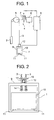
- FIG 1 is a structural diagram showing an elevator apparatus according to Embodiment 1 of the present invention.
- a car 1 and a counterweight 2 are suspended inside a hoistway by a plurality of main ropes 3, and are raised and lowered inside the hoistway by a driving force from a hoisting machine 4.
- the hoisting machine 4 has: a drive sheave 5 onto which the main ropes 3 are wound; a motor 6 that rotates the drive sheave 5; and a brake 7 that brakes rotation of the drive sheave 5 by friction.
- the motor 6 and the brake 7 are controlled by a control apparatus 8.
- the car 1 has: a car frame 9; a cage 10 that is supported by the car frame 9; and a plurality of vibration isolating members 11 that are disposed between a lower portion of the cage 10 and the car frame 9.
- a weighing apparatus 12 for detecting live load inside the car 1 is disposed on an upper beam of the car frame 9. The weighing apparatus 12 generates detection signals in response to the live load inside the car 1. The detection signals from the weighing apparatus 12 are input into the control apparatus 8.
- FIG. 2 is a front elevation showing the car 1 from Figure 1
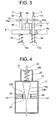
- Figure 3 is an enlargement showing part of Figure 2 .
- Rope end fixing rods 13 are connected to end portions of each of the main ropes 3.
- a plurality of insertion apertures 9a through which the rope end fixing rods 13 are inserted are disposed on the upper beam of the car frame 9.
- Flange-shaped retainers 13a that prevent the rope end fixing rods 13 from being pulled out of the insertion apertures 9a are disposed on lower end portions of each of the rope end fixing rods 13.
- Shackle springs 14 are disposedbetween each of the retainers 13a and the upper beam of the car frame 9.
- the car frame 9 is displaced vertically relative to the rope end fixing rods 13 in response to changes in the live load inside the car 1.
- the shackle springs 14 are expanded and contracted together with the vertical displacement of the car frame 9 relative to the rope end fixing rods 13.
- a detecting plate 15 is mounted to the rope end fixing rods 13 above the car frame 9.
- the detecting plate 15 is pivotably linked to the rope end fixing rods 13 by means of a pivoting shaft 15a.
- the weighing apparatus 12 has: a plurality of supporting members 16 that are installed on the upper beam of the car frame 9; a weighing apparatus main body 17 that is supported by the supporting members 16; and a displacing member (the shaft core) 18 that comes into contact with the detecting plate 15 and displaces vertically relative to the weighing apparatus main body 17 together with the vertical movement of the detecting plate 15 relative to the car frame 9.
- Figure 4 is a cross section showing an internal construction of the weighing apparatus 12 from Figure 3
- Figure 5 is a side elevation showing part of the weighing apparatus 12 from Figure 4
- Figure 6 is a cross section taken along line VI - VI in Figure 5
- a core portion 18a that has a cross sectional diameter that changes continuously in an axial direction is formed on an intermediate portion of the displacing member 18.
- the core portion 18a is formed so as to have a conical shape in which the cross sectional diameter decreases continuously from an upper end portion thereof toward a lower end portion.
- a flange-shaped spring stopping portion 18b is formed in a vicinity of an upper end portion of the displacing member 18.
- the core portion 18a is disposed inside an outer frame 19. Upper and lower end portions of the displacing member 18 project outside the outer frame 19. A preloading spring 20 is disposed between an upper portion of the outer frame 19 and the spring stopping portion 18b. A stopper 21 for restricting upward movement of the displacing member 18 is fixed above the outer frame 19.
- a magnet 22 and first and second yokes 23 and 24 are fixed to the outer frame 19.
- the first yoke 23 has: a first connecting end portion 23a that is connected to a North-seeking (N) pole of the magnet 22; and a first facing end portion 23b that faces the core portion 18a.
- the second yoke 24 has: a second facing end portion 24a that is connected to a South-seeking (S) pole of the magnet 22; and a second connecting end portion 24b that faces the core portion 18a.
- the first facing end portion 23b and the second connecting end portion 24b face each other from opposite sides of the core portion 18a.
- a first magnetic sensor 25 that functions as a displacement detecting portion that outputs detection signals that correspond to the amount of magnetic flux between the first and second facing end portions 23b and 24b is fixed to the first facing end portion 23b.
- a second magnetic sensor 26 that functions as a displacement detecting portion that outputs detection signals that correspond to the amount of magnetic flux between the first and second facing end portions 23b and 24b is fixed to the second connecting end portion 24b.
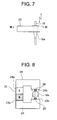
- Figure 7 is a side elevation showing a state in which the displacing member 18 from Figure 5 has been displaced downward
- Figure 8 is a cross section taken along line VIII - VIII in Figure 7 .
- Figure 9 is a block diagram showing functions of the control apparatus 8 from Figure 1 .
- the control apparatus 8 has: first and second load converting portions 27 and 28; first and second determining portions 29 and 30; first and second OR operation portions 31 and 32; and first and second warning issuing portions 33 and 34.
- the detection signals from the magnetic sensors 25 and 26 are converted to a digital form and processed arithmetically in the control apparatus 8.
- the first load converting portion 27 finds the displacement of the displacing member 18 based on the detection signals from the first magnetic sensor 25, and also calculates the live load inside the car 1 using the displacement of the displacing member 18 and the spring modulus of the shackle springs 14.
- the second load converting portion 28 finds the displacement of the displacing member 18 based on the detection signals from the second magnetic sensor 26, and also calculates the live load inside the car 1 using the displacement of the displacing member 18 and the spring modulus of the shackle springs 14.
- the first determining portion 29 determines whether a difference between the loads that have been found by the first and second load converting portions 27 and 28 has reached a preset threshold value, and sends an abnormality detection signal to the first and second OR operation portions 31 and 32 if the threshold value has been reached.
- the second determining portion 30 determines whether a difference between the loads that have been found by the first and second load converting portions 27 and 28 has not reached a preset threshold value, and sends an abnormality detection signal to the first and second OR operation portions 31 and 32 if the threshold value has been reached.
- the first OR operation portions 31 sends a warning issuing command to the first warning issuing portion 33 when an abnormality detection signal is sent from at least one of the first and second determining portions 29 and 30.
- the second OR operation portions 32 sends a warning issuing command to the second warning issuing portion 34 when an abnormality detection signal is sent from at least one of the first and second determining portions 29 and 30.
- the first and second warning issuing portions 33 and 34 transmit signals that notify of an abnormality in the weighing apparatus 12 to a control room if a warning issuing command is received.
- the control apparatus 8 controls operation of the car 1 based on the live load information that has been found by the first or the second load converting portion 27 and 28 if the weighing apparatus 12 is normal.
- control apparatus 8 is constituted by a computer that has: an arithmetic processing portion (CPU); a storage portion (ROM, RAM, hard disk, etc.); and a signal input/output portion.
- CPU central processing unit
- ROM read-only memory
- ROM read-only memory
- hard disk hard disk
- signal input/output portion The functions of the converting portions 27 and 28, the determining portions 29 and 30, the OR operation portions 31 and 32, and the warning issuing portions 33 and 34 are implemented by the computer.
- a program for implementing the functions of the converting portions 27 and 28, the determining portions 29 and 30, the OR operation portions 31 and 32, and the warning issuing portions 33 and 34 is stored in the storage portion of the computer.
- the arithmetic processing portion carries out arithmetic processing relating to the functions of the control apparatus 8 based on the control program.
- a first computer that implements the functions of the first load converting portion 27, the first determining portion 29, the first OR operation portion 31, and the first warning issuing portion 33 and a second computer that implements the functions of the second load converting portion 28, the second determining portion 30, the second OR operation portion 32, and the second warning issuing portion 34 may also be used and communication made mutually possible between the first and second computers.
- the weighing apparatus 12 is reduced in size, enabling costs to be reduced. Because two detection signals are output simultaneously by the weighing apparatus 12, precision in detecting live loads can also be improved. Because the presence or absence of abnormalities in the weighing apparatus 12 is determined in the control apparatus 8 based on the difference between the two detection signals and an abnormality detection signal is output when there is an abnormality, the reliability of the weighing apparatus 12 can be improved.
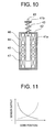
- Figure 10 is a structural diagram showing part of a weighing apparatus of an elevator apparatus according to Embodiment 2 of the present invention.
- a displacing member 41 is placed in contact with a detecting plate 15 that is similar to that of Embodiment 1, for example, and is displaced in a vertical direction (an axial direction) in response to changes in a live load inside a car 1.
- a cylindrical core 41a is mounted to the displacing member 41.
- a flange-shaped spring stopping portion 41b is formed in a vicinity of an upper end portion of the displacing member 41.
- the core 41a is disposed inside an outer frame 42.
- An upper end portion of the displacing member 41 projects outside the outer frame 42.
- a preloading spring 43 is disposed between an upper portion of the outer frame 42 and the spring stopping portion 41b.
- First and second signal transmitting coils 44 and 45 that surround the core 41a and first and second signal receiving coils 46 and 47 that function as a displacement detecting portion are disposed inside the outer frame 42. High-frequency current is passed through the first and second signal transmitting coils 44 and 45. Thus, an induced current is induced in the signal receiving coils 46 and 47. High-frequency output signals from the signal receiving coils 46 and 47 are rectified by diodes, etc., and are sent to a control apparatus 8 ( Figure 9 ) as detection signals.
- Figure 11 is a graph showing relationships between positions of the core 41a and output from the first and second signal receiving coils 46 and 47 from Figure 10 , output from the first signal receiving coil 46 being represented by a solid line and output from the second signal receiving coil 47 by a broken line.
- the degree of coupling of electromagnetic induction between the signal transmitting coils 44 and 45 and the signal receiving coils 46 and 47 changes as the core 41a is displaced downward (to the right in Figure 11 ) such that the current that is output from the first signal receiving coil 46 decreases whereas the current that is output from the second signal receiving coil 47 increases.
- the control apparatus 8 has similar functions to those in Figure 9 .
- a first load converting portion 27 calculates the live load inside the car 1 based on the detection signals from the first signal receiving coil 46.
- a second load converting portion 28 calculates the live load inside the car 1 based on the detection signals from the second signal receiving coil 47.
- the rest of the configuration is similar to that of Embodiment 1.
- the weighing apparatus 12 is reduced in size, enabling costs to be reduced. Because two detection signals are output simultaneously by the weighing apparatus 12, precision in detecting live loads can also be improved. Because the displacement of the displacing member 41 is detected using electromagnetic induction that results from high-frequency currents, even if there are static magnetic disturbances such as when magnetic bodies are in close proximity to the weighing apparatus 12, etc., the magnetic disturbances have no effect, enabling detecting precision to be improved further.
- Figure 12 is a structural diagram showing part of a weighing apparatus of an elevator apparatus according to Embodiment 3 of the present invention.
- a displacing member 51 is placed in contact with a detecting plate 15 that is similar to that of Embodiment 1, for example, and is displaced in a vertical direction (an axial direction) in response to changes in a live load inside a car 1.
- a flange-shaped reflecting plate 51a is mounted to the displacing member 51.
- a flange-shaped spring stopping portion 51b is formed in a vicinity of an upper end portion of the displacing member 51.
- the reflecting plate 51a is disposed inside an outer frame 52. Upper and lower end portions of the displacing member 51 project outside the outer frame 52.
- a preloading spring 53 is disposed between an upper portion of the outer frame 52 and the spring stopping portion 51b.
- a first supporting plate 54 that is positioned above the reflecting plate 51a and a second supporting plate 55 that is positioned below the reflecting plate 51a are fixed to the outer frame 52.
- a first photoemitter 56 and a first photodetector 57 that face an upper surface (first reflecting surface) of the reflecting plate 51a are mounted to the first supporting plate 54.
- a second photoemitter 58 and a second photodetector 59 that face a lower surface (second reflecting surface) of the reflecting plate 51a are mounted to the second supporting plate 55.
- the photoemitters 56 and 58 aim light toward the reflecting plate 51a.
- the photodetectors 57 and 59 receive light that has been reflected by the reflecting plate 51a and generate detection signals that correspond to the intensity of the light received.
- the detection signals from the photodetectors 57 and 59 are sent to a control apparatus 8 ( Figure 9 ).
- the control apparatus 8 has similar functions to those in Figure 9 .
- a first load converting portion 27 finds the displacement of the displacing member 51 based on the detection signals from the first photodetector 57, and also calculates the live load inside the car 1 using the displacement of the displacing member 51 and the spring modulus of the shackle springs 14.
- a second load converting portion 28 finds the displacement of the displacing member 51 based on the detection signals from the second photodetector 59, and also calculates the live load inside the car 1 using the displacement of the displacing member 51 and the spring modulus of the shackle springs 14.
- the load converting portions 27 and 28 may also use differences in the phases of the light received by the photodetectors 57 and 59 to find the displacement of the displacing member 51.
- the rest of the configuration is similar to that of Embodiment 1.
- an elevator apparatus of this kind because the displacement of a single displacing member 51 is detected by two photodetectors 57 and 59, the weighing apparatus 12 is reduced in size, enabling costs to be reduced. Because two detection signals are output simultaneously by the weighing apparatus 12, precision in detecting live loads can also be improved. Because the displacement of the displacing member 51 is detected by optical sensors, magnetic disturbances have no effect, enabling detecting precision to be improved further.
- Figure 13 is a structural diagram showing part of a weighing apparatus of an elevator apparatus according to Embodiment 4 of the present invention.
- a displacing member 61 is placed in contact with a detecting plate 15 that is similar to that of Embodiment 1, for example, and is displaced in a vertical direction (an axial direction) in response to changes in a live load inside a car 1.
- a conical reflecting body 61a is mounted to the displacing member 61.
- a flange-shaped spring stopping portion 61b is formed in a vicinity of an upper end portion of the displacing member 61.
- the reflecting body 61a is disposed inside an outer frame 62. Upper and lower end portions of the displacing member 61 project outside the outer frame 62.
- a preloading spring 63 is disposed between an upper portion of the outer frame 62 and the spring stopping portion 61b.
- First and second supporting plates 64 and 65 are fixed to the outer frame 62.
- a first photoemitter 56 and a first photodetector 57 that face a side surface (reflecting surface) of the reflecting body 61a are mounted to the first supporting plate 64.
- a second photoemitter 58 and a second photodetector 59 that face the side surface of the reflecting body 61a on an opposite side from the first photoemitter 56 and the first photodetector 57 are mounted to the second supporting plate 65.
- the rest of the configuration is similar to that of Embodiment 3.
- an elevator apparatus of this kind because the displacement of a single displacing member 61 is detected by two photodetectors 57 and 59, the weighing apparatus 12 is reduced in size, enabling costs to be reduced. Because two detection signals are output simultaneously by the weighing apparatus 12, precision in detecting live loads can also be improved. Because the displacement of the displacing member 61 is detected by optical sensors, magnetic disturbances have no effect, enabling detecting precision to be improved further.
- Figure 14 is a structural diagram showing part of a weighing apparatus of an elevator apparatus according to Embodiment 5 of the present invention.
- first and third magnetic sensors 25 and 35 that function as a displacement detecting portion that outputs detection signals that correspond to the amount of magnetic flux between first and second facing end portions 23b and 24b of a first yoke 23 and a second yoke 24 are fixed to the first facing end portion 23b.
- Second and fourth magnetic sensors 26 and 36 that function as a displacement detecting portion that outputs detection signals that correspond to the amount of magnetic flux between the first and second facing end portions 23b and 24b are fixed to the second connecting end portion 24b.
- the first and second magnetic sensors 25 and 26 are disposed symmetrically on opposite sides of a shaft axis of a displacing member 18 from each other in a first plane that is perpendicular to the shaft axis of the displacing member 18.
- the third and fourth magnetic sensors 35 and 36 are disposed symmetrically on opposite sides of the shaft axis of the displacing member 18 from each other in a second plane that is parallel to the plane in which the first and second magnetic sensors 25 and 26 are disposed.
- the detection signals from the first and second magnetic sensors 25 and 26 are input into a first averaging circuit 37.
- the first averaging circuit 37 inputs a signal to the control apparatus 8 that is an average of the detection signals from the first and second magnetic sensors 25 and 26.
- the detection signals from the third and fourth magnetic sensors 35 and 36 are input into a second averaging circuit 38.
- the second averaging circuit 38 inputs a signal to the control apparatus 8 that is an average of the detection signals from the third and fourth magnetic sensors 35 and 36.
- the control apparatus 8 has similar functions to those in Figure 9 .
- a first load converting portion 27 calculates the live load inside the car 1 based on the signals from the first averaging circuit 37.
- a second load converting portion 28 calculates the live load inside the car 1 based on the signals from the second signal averaging circuit 38.
- the rest of the configuration is similar to that of Embodiment 1.
- averaging processes such as those shown in Embodiment 5 can also be applied to the sensors of detection methods such as those shown in Embodiments 2 through 4, enabling the effects of shaft deviation of the displacing member to be reduced in a similar manner.
- the averaging processes may be performed on the signals before they are input into the control apparatus, or they may also be performed inside the control apparatus.
- the data may be averaged either before load conversion or after load conversion.
- Figure 15 is a front elevation showing a car of an elevator apparatus according to Embodiment 6 of the present invention.
- a car 1 is suspended at two positions that are spaced in a width direction of the car 1. Consequently, first and second weighing apparatuses 12a and 12b are installed on a car frame 9.
- the configuration of each of the weighing apparatuses 12a and 12b is similar to that of Embodiment 1.
- FIG 16 is a block diagram showing functions of a control apparatus 8 of the elevator apparatus in Figure 15 .
- a first load converting portion 71 calculates load based on the detection signals from the first magnetic sensor 25 of the first weighing apparatus 12a.
- a second load converting portion 72 calculates load based on the detection signals from the second magnetic sensor 26 of the first weighing apparatus 12a.
- a third load converting portion 73 calculates load based on the detection signals from the first magnetic sensor 25 of the second weighing apparatus 12b.
- a fourth load converting portion 74 calculates load based on the detection signals from the second magnetic sensor 26 of the second weighing apparatus 12b.
- the loads that were found by the first load converting portion 71 and the third load converting portions 73 are added together by the first adding operation portion 75, thereby obtaining the live load inside the car 1.
- the loads that were found by the second load converting portion 72 and the fourth load converting portion 74 are added together by the second adding operation portion 76, thereby obtaining another calculated result for the live load inside the car 1.
- the rest of the configuration is similar to that of Embodiment 1.
- a plurality of calculated results for the live load inside the car 1 can be obtained by installing weighing apparatuses 12a and 12b having a plurality of sensors 25 and 26 at each of the suspension points and adding combinations of signals from different sensors 25 and 26 on different weighing apparatuses 12a and 12b.
- the installation positions of the weighing apparatuses are not limited to car suspension portions (main rope connection portions), and may also be between the car frame and a lower portion of the cage, or on a supporting portion of the hoisting machine, etc., for example.
- mechanical displacement of the displacing member is detected using magnetic sensors, induced current sensors, or optical sensors, but the displacement detecting portion is not limited to these detection methods, and strain sensors, etc., may also be used, for example.
- the presence or absence of abnormality is determined by comparing a plurality of calculated results for the live load, but a process of comparative determination does not necessarily have to be carried out, and the calculated results of the live load can also be used respectively for distinct purposes.
- FIG 17 is a block diagram showing part of a control system of an elevator apparatus according to Embodiment 7 of the present invention.
- a displacing member (not shown) that is displaced in response to changes in a live load inside a car 1 ( Figure 1 ) and first and second displacement detecting portions 82 and 83 that detect the displacement of the displacing member and output detection signals that correspond to the live load are disposed on a weighing apparatus 81.
- the specific construction of the weighing apparatus 81 is similar to any of those shown in Embodiments 1 through 6, for example.
- the detection signals from the first displacement detecting portion 82 are input into a control apparatus 8 that controls operation of the car 1.
- the control apparatus 8 has a first load converting portion 84 and a driving pattern operation portion 85.
- the first load converting portion 84 calculates the live load inside the car 1 based on the detection signals from the first displacement detecting portion 82.
- the driving pattern operation portion 85 calculates the driving pattern of a hoisting machine 4 ( Figure 1 ) so as to correspond to the live load that has been found by the first load converting portion 84.
- the detection signals from the second displacement detecting portion 83 are input into a safety apparatus 86 that monitors the presence or absence of abnormalities in the elevator apparatus.
- the safety apparatus 86 has a second load converting portion 87 and an emergency braking portion 88.
- the second load converting portion 87 calculates the live load inside the car 1 based on the detection signals from the second displacement detecting portion 83.
- the emergency braking portion 88 determines the presence or absence of abnormalities in the elevator apparatus based on car position information and car velocity information, and outputs a command signal to make the car 1 perform an emergency stop if an abnormality is detected.
- the emergency braking portion 88 controls the emergency braking method so as to correspond to the live load that has been found by the second load converting portion 87.
- the emergency braking portion 88 may vary the braking force during emergency braking so as to correspond to the live load, for example, to avoid subjecting the passengers in the car 1 to discomfort due to unnecessary deceleration.
- Examples of methods for controlling the braking force include methods in which a plurality of brakes 7 are disposed on a single hoisting machine 4 and the timing of operation of the brakes 7 is offset during emergency braking, etc., for example.
- the control apparatus 8 can be constituted by a computer. In that case, the functions of the first load converting portion 84 and the driving pattern operation portion 85 are implemented by the computer of the control apparatus 8.
- the safety apparatus 86 can be constituted by a separate computer from the computer of the control apparatus 8, for example. In that case, the functions of the second load converting portion 87 and the emergency braking portion 88 are implemented by the computer of the safety apparatus 86.
- the safety apparatus 86 can also be constituted by an analog electrical circuit.
- the detection signals for the control apparatus 8 and the detection signals for the safety apparatus 86 are obtained from a single weighing apparatus 81, the weighing apparatus 81 is reduced in size, enabling costs to be reduced. Because the detection signals for the control apparatus 8 and the detection signals for the safety apparatus 86 are obtained separately, reliability can be improved.
- the detection signals that are output from the weighing apparatus 81 are assigned to the control apparatus 8 and the safety apparatus 86, but the detection signals may also be assigned to other apparatuses.
- Figure 18 is a block diagram showing part of a control system of an elevator apparatus according to Embodiment 8 of the present invention.
- electric power is supplied to a first displacement detecting portion 82 and a control apparatus 8 from a first power source 89.
- Electric power is supplied to a second displacement detecting portion 83 and a safety apparatus 86 from a second power source 90.
- a battery 91 is also connected to the second power source 90.
- the second power source 90 is backed up by the battery 91 during power outages.
- the rest of the configuration is similar to that of Embodiment 7.
Landscapes
- Engineering & Computer Science (AREA)
- Automation & Control Theory (AREA)
- Mechanical Engineering (AREA)
- Computer Networks & Wireless Communication (AREA)
- Indicating And Signalling Devices For Elevators (AREA)
- Maintenance And Inspection Apparatuses For Elevators (AREA)
- Elevator Control (AREA)
- Control And Safety Of Cranes (AREA)
Abstract
Description
- The present invention relates to an elevator apparatus that has a weighing apparatus for detecting a live load inside a car.
- In conventional elevator apparatuses, a plurality of weighing apparatuses are installed between a lower portion of a car and a car frame. The presence or absence of abnormalities in the weighing apparatuses is determined by comparing signals from the weighing apparatuses using monitoring apparatuses. If an abnormality is detected in the weighing apparatuses, warning of the abnormality is performed by a warning portion (see
Patent Document 1, for example). -
Patent Document 1
Japanese Patent Laid-Open No.HEI 6-234476 (Gazette - In conventional elevator apparatuses such as that described above, costs are increased since a plurality of weighing apparatuses are used. Furthermore, since the detecting positions are dispersed, irregularities may arise in the detected values depending on positions of passengers in the car, etc., making precision poor.
- The present invention aims to solve the above problems and an object of the present invention is to provide an elevator apparatus that enables costs to be reduced by reducing weighing apparatuses in size, and that also enables precision in detecting live loads to be improved.
- An elevator apparatus according to the present invention includes a weighing apparatus that has: a displacing member that is displaced in response to changes in live load inside a car; and a plurality of displacement detecting portions that detect displacement of the displacing member and output a detection signal that corresponds to the live load.
-
-
Figure 1 is a structural diagram showing an elevator apparatus according toEmbodiment 1 of the present invention; -
Figure 2 is a front elevation showing a car fromFigure 1 ; -
Figure 3 is an enlargement showing part ofFigure 2 ; -
Figure 4 is a cross section showing an internal construction of a weighing apparatus fromFigure 3 ; -
Figure 5 is a side elevation showing part of the weighing apparatus fromFigure 4 ; -
Figure 6 is a cross section taken along line VI - VI inFigure 5 ; -
Figure 7 is a side elevation showing a state in which a displacing member fromFigure 5 has been displaced downward; -
Figure 8 is a cross section taken along line VIII - VIII inFigure 7 ; -
Figure 9 is a block diagram showing functions of a control apparatus fromFigure 1 ; -
Figure 10 is a structural diagram showing part of a weighing apparatus of an elevator apparatus according toEmbodiment 2 of the present invention; -
Figure 11 is a graph showing relationships between positions of a core and output from first and second signal receiving coils fromFigure 10 ; -
Figure 12 is a structural diagram showing part of a weighing apparatus of an elevator apparatus according toEmbodiment 3 of the present invention; -
Figure 13 is a structural diagram showing part of a weighing apparatus of an elevator apparatus according toEmbodiment 4 of the present invention; -
Figure 14 is a structural diagram showing part of a weighing apparatus of an elevator apparatus according toEmbodiment 5 of the present invention; -
Figure 15 is a front elevation showing a car of an elevator apparatus according toEmbodiment 6 of the present invention; -
Figure 16 is a block diagram showing functions of a control apparatus of the elevator apparatus inFigure 15 ; -
Figure 17 is a block diagram showing part of a control system of an elevator apparatus according toEmbodiment 7 of the present invention; and -
Figure 18 is a block diagram showing part of a control system of an elevator apparatus according toEmbodiment 8 of the present invention. - Preferred embodiments of the present invention will now be explained with reference to the drawings.
-
Figure 1 is a structural diagram showing an elevator apparatus according toEmbodiment 1 of the present invention. In the figure, acar 1 and acounterweight 2 are suspended inside a hoistway by a plurality ofmain ropes 3, and are raised and lowered inside the hoistway by a driving force from a hoistingmachine 4. The hoistingmachine 4 has: adrive sheave 5 onto which themain ropes 3 are wound; amotor 6 that rotates thedrive sheave 5; and abrake 7 that brakes rotation of thedrive sheave 5 by friction. Themotor 6 and thebrake 7 are controlled by acontrol apparatus 8. - The
car 1 has: acar frame 9; acage 10 that is supported by thecar frame 9; and a plurality ofvibration isolating members 11 that are disposed between a lower portion of thecage 10 and thecar frame 9. Aweighing apparatus 12 for detecting live load inside thecar 1 is disposed on an upper beam of thecar frame 9. Theweighing apparatus 12 generates detection signals in response to the live load inside thecar 1. The detection signals from theweighing apparatus 12 are input into thecontrol apparatus 8. -
Figure 2 is a front elevation showing thecar 1 fromFigure 1 , andFigure 3 is an enlargement showing part ofFigure 2 . Ropeend fixing rods 13 are connected to end portions of each of themain ropes 3. A plurality ofinsertion apertures 9a through which the ropeend fixing rods 13 are inserted are disposed on the upper beam of thecar frame 9. Flange-shaped retainers 13a that prevent the ropeend fixing rods 13 from being pulled out of theinsertion apertures 9a are disposed on lower end portions of each of the ropeend fixing rods 13. -
Shackle springs 14 are disposedbetween each of theretainers 13a and the upper beam of thecar frame 9. Thecar frame 9 is displaced vertically relative to the ropeend fixing rods 13 in response to changes in the live load inside thecar 1. Theshackle springs 14 are expanded and contracted together with the vertical displacement of thecar frame 9 relative to the ropeend fixing rods 13. - A detecting
plate 15 is mounted to the ropeend fixing rods 13 above thecar frame 9. The detectingplate 15 is pivotably linked to the ropeend fixing rods 13 by means of a pivotingshaft 15a. - The
weighing apparatus 12 has: a plurality of supportingmembers 16 that are installed on the upper beam of thecar frame 9; a weighing apparatusmain body 17 that is supported by the supportingmembers 16; and a displacing member (the shaft core) 18 that comes into contact with the detectingplate 15 and displaces vertically relative to the weighing apparatusmain body 17 together with the vertical movement of the detectingplate 15 relative to thecar frame 9. -
Figure 4 is a cross section showing an internal construction of theweighing apparatus 12 fromFigure 3 ,Figure 5 is a side elevation showing part of theweighing apparatus 12 fromFigure 4 , andFigure 6 is a cross section taken along line VI - VI inFigure 5 . Acore portion 18a that has a cross sectional diameter that changes continuously in an axial direction is formed on an intermediate portion of the displacingmember 18. Thecore portion 18a is formed so as to have a conical shape in which the cross sectional diameter decreases continuously from an upper end portion thereof toward a lower end portion. A flange-shapedspring stopping portion 18b is formed in a vicinity of an upper end portion of the displacingmember 18. - The
core portion 18a is disposed inside anouter frame 19. Upper and lower end portions of the displacingmember 18 project outside theouter frame 19. A preloadingspring 20 is disposed between an upper portion of theouter frame 19 and thespring stopping portion 18b. Astopper 21 for restricting upward movement of the displacingmember 18 is fixed above theouter frame 19. - A
magnet 22 and first andsecond yokes outer frame 19. Thefirst yoke 23 has: a first connectingend portion 23a that is connected to a North-seeking (N) pole of themagnet 22; and a first facingend portion 23b that faces thecore portion 18a. Thesecond yoke 24 has: a second facingend portion 24a that is connected to a South-seeking (S) pole of themagnet 22; and a second connectingend portion 24b that faces thecore portion 18a. The first facingend portion 23b and the second connectingend portion 24b face each other from opposite sides of thecore portion 18a. - A first
magnetic sensor 25 that functions as a displacement detecting portion that outputs detection signals that correspond to the amount of magnetic flux between the first and second facingend portions end portion 23b. A secondmagnetic sensor 26 that functions as a displacement detecting portion that outputs detection signals that correspond to the amount of magnetic flux between the first and second facingend portions end portion 24b. -
Figure 7 is a side elevation showing a state in which the displacingmember 18 fromFigure 5 has been displaced downward, andFigure 8 is a cross section taken along line VIII - VIII inFigure 7 . When the detectingplate 15 is displaced vertically due to a change in the live load inside thecar 1, the displacingmember 18 is also mechanically displaced vertically together therewith. When the displacingmember 18 is displaced vertically, the cross-sectional area of thecore portion 18a that is positioned between the facingend portions core portion 18a is increased, the amount of magnetic flux passing between the facingendportions Figure 8 . Consequently, themagnetic sensors car 1. -
Figure 9 is a block diagram showing functions of thecontrol apparatus 8 fromFigure 1 . Thecontrol apparatus 8 has: first and secondload converting portions portions operation portions warning issuing portions magnetic sensors control apparatus 8. - The first
load converting portion 27 finds the displacement of the displacingmember 18 based on the detection signals from the firstmagnetic sensor 25, and also calculates the live load inside thecar 1 using the displacement of the displacingmember 18 and the spring modulus of the shackle springs 14. The secondload converting portion 28 finds the displacement of the displacingmember 18 based on the detection signals from the secondmagnetic sensor 26, and also calculates the live load inside thecar 1 using the displacement of the displacingmember 18 and the spring modulus of the shackle springs 14. - The first determining
portion 29 determines whether a difference between the loads that have been found by the first and secondload converting portions operation portions portion 30 determines whether a difference between the loads that have been found by the first and secondload converting portions operation portions - The first OR
operation portions 31 sends a warning issuing command to the firstwarning issuing portion 33 when an abnormality detection signal is sent from at least one of the first and second determiningportions operation portions 32 sends a warning issuing command to the secondwarning issuing portion 34 when an abnormality detection signal is sent from at least one of the first and second determiningportions - The first and second
warning issuing portions apparatus 12 to a control room if a warning issuing command is received. Thecontrol apparatus 8 controls operation of thecar 1 based on the live load information that has been found by the first or the secondload converting portion apparatus 12 is normal. - Here, the
control apparatus 8 is constituted by a computer that has: an arithmetic processing portion (CPU); a storage portion (ROM, RAM, hard disk, etc.); and a signal input/output portion. The functions of the convertingportions portions OR operation portions warning issuing portions - In other words, a program for implementing the functions of the converting
portions portions OR operation portions warning issuing portions control apparatus 8 based on the control program. - A first computer that implements the functions of the first
load converting portion 27, the first determiningportion 29, the first ORoperation portion 31, and the firstwarning issuing portion 33 and a second computer that implements the functions of the secondload converting portion 28, the second determiningportion 30, the second ORoperation portion 32, and the secondwarning issuing portion 34 may also be used and communication made mutually possible between the first and second computers. - In an elevator apparatus of this kind, because the displacement of a single displacing
member 18 is detected by twomagnetic sensors apparatus 12 is reduced in size, enabling costs to be reduced. Because two detection signals are output simultaneously by the weighingapparatus 12, precision in detecting live loads can also be improved.
Because the presence or absence of abnormalities in the weighingapparatus 12 is determined in thecontrol apparatus 8 based on the difference between the two detection signals and an abnormality detection signal is output when there is an abnormality, the reliability of the weighingapparatus 12 can be improved. - Next,
Figure 10 is a structural diagram showing part of a weighing apparatus of an elevator apparatus according toEmbodiment 2 of the present invention. In the figure, a displacingmember 41 is placed in contact with a detectingplate 15 that is similar to that ofEmbodiment 1, for example, and is displaced in a vertical direction (an axial direction) in response to changes in a live load inside acar 1. Acylindrical core 41a is mounted to the displacingmember 41. A flange-shapedspring stopping portion 41b is formed in a vicinity of an upper end portion of the displacingmember 41. - The
core 41a is disposed inside anouter frame 42. An upper end portion of the displacingmember 41 projects outside theouter frame 42. A preloadingspring 43 is disposed between an upper portion of theouter frame 42 and thespring stopping portion 41b. - First and second
signal transmitting coils core 41a and first and secondsignal receiving coils outer frame 42. High-frequency current is passed through the first and secondsignal transmitting coils Figure 9 ) as detection signals. -
Figure 11 is a graph showing relationships between positions of thecore 41a and output from the first and secondsignal receiving coils Figure 10 , output from the firstsignal receiving coil 46 being represented by a solid line and output from the secondsignal receiving coil 47 by a broken line. As shown inFigure 11 , the degree of coupling of electromagnetic induction between the signal transmitting coils 44 and 45 and the signal receiving coils 46 and 47 changes as thecore 41a is displaced downward (to the right inFigure 11 ) such that the current that is output from the firstsignal receiving coil 46 decreases whereas the current that is output from the secondsignal receiving coil 47 increases. - The
control apparatus 8 has similar functions to those inFigure 9 . A firstload converting portion 27 calculates the live load inside thecar 1 based on the detection signals from the firstsignal receiving coil 46. A secondload converting portion 28 calculates the live load inside thecar 1 based on the detection signals from the secondsignal receiving coil 47. The rest of the configuration is similar to that ofEmbodiment 1. - In an elevator apparatus of this kind, because the displacement of a single displacing
member 41 is detected by two signal receiving coils 46 and 47, the weighingapparatus 12 is reduced in size, enabling costs to be reduced. Because two detection signals are output simultaneously by the weighingapparatus 12, precision in detecting live loads can also be improved.
Because the displacement of the displacingmember 41 is detected using electromagnetic induction that results from high-frequency currents, even if there are static magnetic disturbances such as when magnetic bodies are in close proximity to the weighingapparatus 12, etc., the magnetic disturbances have no effect, enabling detecting precision to be improved further. - Next,
Figure 12 is a structural diagram showing part of a weighing apparatus of an elevator apparatus according toEmbodiment 3 of the present invention. In the figure, a displacingmember 51 is placed in contact with a detectingplate 15 that is similar to that ofEmbodiment 1, for example, and is displaced in a vertical direction (an axial direction) in response to changes in a live load inside acar 1. A flange-shaped reflectingplate 51a is mounted to the displacingmember 51. A flange-shapedspring stopping portion 51b is formed in a vicinity of an upper end portion of the displacingmember 51. - The reflecting
plate 51a is disposed inside anouter frame 52. Upper and lower end portions of the displacingmember 51 project outside theouter frame 52. A preloadingspring 53 is disposed between an upper portion of theouter frame 52 and thespring stopping portion 51b. - A first supporting
plate 54 that is positioned above the reflectingplate 51a and a second supportingplate 55 that is positioned below the reflectingplate 51a are fixed to theouter frame 52. Afirst photoemitter 56 and afirst photodetector 57 that face an upper surface (first reflecting surface) of the reflectingplate 51a are mounted to the first supportingplate 54. Asecond photoemitter 58 and asecond photodetector 59 that face a lower surface (second reflecting surface) of the reflectingplate 51a are mounted to the second supportingplate 55. - The
photoemitters plate 51a. Thephotodetectors plate 51a and generate detection signals that correspond to the intensity of the light received. The detection signals from thephotodetectors Figure 9 ). - The
control apparatus 8 has similar functions to those inFigure 9 . A firstload converting portion 27 finds the displacement of the displacingmember 51 based on the detection signals from thefirst photodetector 57, and also calculates the live load inside thecar 1 using the displacement of the displacingmember 51 and the spring modulus of the shackle springs 14. A secondload converting portion 28 finds the displacement of the displacingmember 51 based on the detection signals from thesecond photodetector 59, and also calculates the live load inside thecar 1 using the displacement of the displacingmember 51 and the spring modulus of the shackle springs 14. Theload converting portions photodetectors member 51. The rest of the configuration is similar to that ofEmbodiment 1. - In an elevator apparatus of this kind, because the displacement of a single displacing
member 51 is detected by twophotodetectors apparatus 12 is reduced in size, enabling costs to be reduced. Because two detection signals are output simultaneously by the weighingapparatus 12, precision in detecting live loads can also be improved.
Because the displacement of the displacingmember 51 is detected by optical sensors, magnetic disturbances have no effect, enabling detecting precision to be improved further. - Next,
Figure 13 is a structural diagram showing part of a weighing apparatus of an elevator apparatus according toEmbodiment 4 of the present invention. In the figure, a displacingmember 61 is placed in contact with a detectingplate 15 that is similar to that ofEmbodiment 1, for example, and is displaced in a vertical direction (an axial direction) in response to changes in a live load inside acar 1. A conical reflectingbody 61a is mounted to the displacingmember 61. A flange-shapedspring stopping portion 61b is formed in a vicinity of an upper end portion of the displacingmember 61. - The reflecting
body 61a is disposed inside anouter frame 62. Upper and lower end portions of the displacingmember 61 project outside theouter frame 62. A preloadingspring 63 is disposed between an upper portion of theouter frame 62 and thespring stopping portion 61b. - First and second supporting
plates outer frame 62. Afirst photoemitter 56 and afirst photodetector 57 that face a side surface (reflecting surface) of the reflectingbody 61a are mounted to the first supportingplate 64. Asecond photoemitter 58 and asecond photodetector 59 that face the side surface of the reflectingbody 61a on an opposite side from thefirst photoemitter 56 and thefirst photodetector 57 are mounted to the second supportingplate 65. The rest of the configuration is similar to that ofEmbodiment 3. - In an elevator apparatus of this kind, because the displacement of a single displacing
member 61 is detected by twophotodetectors apparatus 12 is reduced in size, enabling costs to be reduced. Because two detection signals are output simultaneously by the weighingapparatus 12, precision in detecting live loads can also be improved.
Because the displacement of the displacingmember 61 is detected by optical sensors, magnetic disturbances have no effect, enabling detecting precision to be improved further. - Next,
Figure 14 is a structural diagram showing part of a weighing apparatus of an elevator apparatus according toEmbodiment 5 of the present invention. In the figure, first and thirdmagnetic sensors end portions first yoke 23 and asecond yoke 24 are fixed to the first facingend portion 23b. Second and fourthmagnetic sensors end portions end portion 24b. - The first and second
magnetic sensors member 18 from each other in a first plane that is perpendicular to the shaft axis of the displacingmember 18. The third and fourthmagnetic sensors member 18 from each other in a second plane that is parallel to the plane in which the first and secondmagnetic sensors - The detection signals from the first and second
magnetic sensors first averaging circuit 37. Thefirst averaging circuit 37 inputs a signal to thecontrol apparatus 8 that is an average of the detection signals from the first and secondmagnetic sensors magnetic sensors second averaging circuit 38. Thesecond averaging circuit 38 inputs a signal to thecontrol apparatus 8 that is an average of the detection signals from the third and fourthmagnetic sensors - The
control apparatus 8 has similar functions to those inFigure 9 . A firstload converting portion 27 calculates the live load inside thecar 1 based on the signals from thefirst averaging circuit 37. A secondload converting portion 28 calculates the live load inside thecar 1 based on the signals from the secondsignal averaging circuit 38. The rest of the configuration is similar to that ofEmbodiment 1. - In an elevator apparatus of this kind, because signals from sensors that are positioned on mutually opposite sides of the displacing
member 18 are averaged, irregularities in the detection signals that result from shaft deviation of the displacingmember 18 are canceled out, enabling detecting precision to be improved. - Moreover, averaging processes such as those shown in
Embodiment 5 can also be applied to the sensors of detection methods such as those shown inEmbodiments 2 through 4, enabling the effects of shaft deviation of the displacing member to be reduced in a similar manner.
The averaging processes may be performed on the signals before they are input into the control apparatus, or they may also be performed inside the control apparatus.
In addition, if the averaging processes are performed inside the control apparatus, the data may be averaged either before load conversion or after load conversion. - Next,
Figure 15 is a front elevation showing a car of an elevator apparatus according toEmbodiment 6 of the present invention. In this example, acar 1 is suspended at two positions that are spaced in a width direction of thecar 1. Consequently, first and second weighingapparatuses car frame 9. The configuration of each of the weighingapparatuses Embodiment 1. -
Figure 16 is a block diagram showing functions of acontrol apparatus 8 of the elevator apparatus inFigure 15 . A firstload converting portion 71 calculates load based on the detection signals from the firstmagnetic sensor 25 of the first weighingapparatus 12a. A secondload converting portion 72 calculates load based on the detection signals from the secondmagnetic sensor 26 of the first weighingapparatus 12a. A thirdload converting portion 73 calculates load based on the detection signals from the firstmagnetic sensor 25 of the second weighingapparatus 12b. A fourthload converting portion 74 calculates load based on the detection signals from the secondmagnetic sensor 26 of the second weighingapparatus 12b. - The loads that were found by the first
load converting portion 71 and the thirdload converting portions 73 are added together by the first addingoperation portion 75, thereby obtaining the live load inside thecar 1. The loads that were found by the secondload converting portion 72 and the fourthload converting portion 74 are added together by the second addingoperation portion 76, thereby obtaining another calculated result for the live load inside thecar 1. The rest of the configuration is similar to that ofEmbodiment 1. - Thus, if a plurality of suspension points are disposed so as to be distributed on the
car 1, a plurality of calculated results for the live load inside thecar 1 can be obtained by installing weighingapparatuses sensors different sensors apparatuses - Moreover, the installation positions of the weighing apparatuses are not limited to car suspension portions (main rope connection portions), and may also be between the car frame and a lower portion of the cage, or on a supporting portion of the hoisting machine, etc., for example.
In the above examples, mechanical displacement of the displacing member is detected using magnetic sensors, induced current sensors, or optical sensors, but the displacement detecting portion is not limited to these detection methods, and strain sensors, etc., may also be used, for example.
In addition, inEmbodiments 1 through 6, the presence or absence of abnormality is determined by comparing a plurality of calculated results for the live load, but a process of comparative determination does not necessarily have to be carried out, and the calculated results of the live load can also be used respectively for distinct purposes. - Next,
Figure 17 is a block diagram showing part of a control system of an elevator apparatus according toEmbodiment 7 of the present invention. In the figure, a displacing member (not shown) that is displaced in response to changes in a live load inside a car 1 (Figure 1 ) and first and seconddisplacement detecting portions apparatus 81. The specific construction of the weighingapparatus 81 is similar to any of those shown inEmbodiments 1 through 6, for example. - The detection signals from the first
displacement detecting portion 82 are input into acontrol apparatus 8 that controls operation of thecar 1. Thecontrol apparatus 8 has a firstload converting portion 84 and a drivingpattern operation portion 85. The firstload converting portion 84 calculates the live load inside thecar 1 based on the detection signals from the firstdisplacement detecting portion 82. The drivingpattern operation portion 85 calculates the driving pattern of a hoisting machine 4 (Figure 1 ) so as to correspond to the live load that has been found by the firstload converting portion 84. - The detection signals from the second
displacement detecting portion 83 are input into asafety apparatus 86 that monitors the presence or absence of abnormalities in the elevator apparatus. Thesafety apparatus 86 has a secondload converting portion 87 and anemergency braking portion 88. The secondload converting portion 87 calculates the live load inside thecar 1 based on the detection signals from the seconddisplacement detecting portion 83. - The
emergency braking portion 88 determines the presence or absence of abnormalities in the elevator apparatus based on car position information and car velocity information, and outputs a command signal to make thecar 1 perform an emergency stop if an abnormality is detected. Here, theemergency braking portion 88 controls the emergency braking method so as to correspond to the live load that has been found by the secondload converting portion 87. - The
emergency braking portion 88 may vary the braking force during emergency braking so as to correspond to the live load, for example, to avoid subjecting the passengers in thecar 1 to discomfort due to unnecessary deceleration. Examples of methods for controlling the braking force include methods in which a plurality ofbrakes 7 are disposed on asingle hoisting machine 4 and the timing of operation of thebrakes 7 is offset during emergency braking, etc., for example. - The
control apparatus 8 can be constituted by a computer. In that case, the functions of the firstload converting portion 84 and the drivingpattern operation portion 85 are implemented by the computer of thecontrol apparatus 8. Thesafety apparatus 86 can be constituted by a separate computer from the computer of thecontrol apparatus 8, for example. In that case, the functions of the secondload converting portion 87 and theemergency braking portion 88 are implemented by the computer of thesafety apparatus 86. Thesafety apparatus 86 can also be constituted by an analog electrical circuit. - In an elevator apparatus of this kind, because the detection signals for the
control apparatus 8 and the detection signals for thesafety apparatus 86 are obtained from a single weighingapparatus 81, the weighingapparatus 81 is reduced in size, enabling costs to be reduced. Because the detection signals for thecontrol apparatus 8 and the detection signals for thesafety apparatus 86 are obtained separately, reliability can be improved. - Moreover, in
Embodiment 7, the detection signals that are output from the weighingapparatus 81 are assigned to thecontrol apparatus 8 and thesafety apparatus 86, but the detection signals may also be assigned to other apparatuses. - Next,
Figure 18 is a block diagram showing part of a control system of an elevator apparatus according toEmbodiment 8 of the present invention. In the figure, electric power is supplied to a firstdisplacement detecting portion 82 and acontrol apparatus 8 from afirst power source 89. Electric power is supplied to a seconddisplacement detecting portion 83 and asafety apparatus 86 from asecond power source 90. Abattery 91 is also connected to thesecond power source 90. Thesecond power source 90 is backed up by thebattery 91 during power outages. The rest of the configuration is similar to that ofEmbodiment 7. - In an elevator apparatus of this kind, because the live load can be found and the emergency braking method controlled even during power outages, reliability can be improved.
Claims (4)
- An elevator apparatus comprising:a weighing apparatus that has:a displacing member that is displaced in response to changes in live load inside a car; anda plurality of displacement detecting portions that detect displacement of the displacing member and output a detection signal that corresponds to the live load.
- An elevator apparatus according to Claim 1, further comprising:a control apparatus that controls operation of the car based on a signal from the displacement detecting portions,wherein:the displacement detecting portions include first and second displacement detecting portions, andthe control apparatus determines whether a difference between a detection signal from the first displacement detecting portions and a detection signal from the second displacement detecting portions has reached a threshold value, and generates an abnormality detection signal if the threshold value has been reached.
- An elevator apparatus according to Claim 1, further comprising:a control apparatus that controls operation of the car; anda safety apparatus for emergency braking the car if there is an abnormality,wherein:
the displacement detecting portions include first and second displacement detecting portions;
the control apparatus controls operation of the car in response to a detection signal from the first displacement detecting portions; and
the safety apparatus controls a braking force during emergency braking in response to a detection signal from the second displacement detecting portions. - An elevator apparatus according to Claim 3, further comprising a battery that supplies electric power to the safety apparatus during power outages.
Applications Claiming Priority (1)
| Application Number | Priority Date | Filing Date | Title |
|---|---|---|---|
| PCT/JP2005/018463 WO2007039932A1 (en) | 2005-10-05 | 2005-10-05 | Elevator device |
Publications (2)
| Publication Number | Publication Date |
|---|---|
| EP1932794A1 true EP1932794A1 (en) | 2008-06-18 |
| EP1932794A4 EP1932794A4 (en) | 2012-09-05 |
Family
ID=37905978
Family Applications (1)
| Application Number | Title | Priority Date | Filing Date |
|---|---|---|---|
| EP05790458A Withdrawn EP1932794A4 (en) | 2005-10-05 | 2005-10-05 | LIFT DEVICE |
Country Status (5)
| Country | Link |
|---|---|
| EP (1) | EP1932794A4 (en) |
| JP (1) | JP5014788B2 (en) |
| KR (1) | KR100932582B1 (en) |
| CN (1) | CN101035732A (en) |
| WO (1) | WO2007039932A1 (en) |
Families Citing this family (3)
| Publication number | Priority date | Publication date | Assignee | Title |
|---|---|---|---|---|
| JP5196369B2 (en) * | 2008-03-05 | 2013-05-15 | 東芝エレベータ株式会社 | Elevator maintenance system |
| JP2011051764A (en) * | 2009-09-03 | 2011-03-17 | Toshiba Elevator Co Ltd | Elevator |
| WO2019207716A1 (en) * | 2018-04-26 | 2019-10-31 | 三菱電機株式会社 | Elevator control device |
Family Cites Families (6)
| Publication number | Priority date | Publication date | Assignee | Title |
|---|---|---|---|---|
| JPS5570681A (en) * | 1978-11-17 | 1980-05-28 | Hitachi Ltd | Elevator load detector |
| US4793442A (en) * | 1987-11-05 | 1988-12-27 | Schindler Elevator Corporation | Method and apparatus for providing pre-travel balancing energy to an elevator drive |
| US5149922A (en) * | 1989-09-08 | 1992-09-22 | Mitsubishi Denki Kabushiki Kaisha | Elevator load detector device using movable detector plates |
| JPH07157211A (en) * | 1993-12-03 | 1995-06-20 | Mitsubishi Electric Corp | Elevator brake equipment |
| JP2002338164A (en) * | 2001-05-17 | 2002-11-27 | Hitachi Ltd | Elevator load detection circuit |
| JP2003221171A (en) * | 2002-01-31 | 2003-08-05 | Hitachi Ltd | Elevator brake system |
-
2005
- 2005-10-05 KR KR1020077010049A patent/KR100932582B1/en not_active Expired - Fee Related
- 2005-10-05 JP JP2006526462A patent/JP5014788B2/en not_active Expired - Fee Related
- 2005-10-05 WO PCT/JP2005/018463 patent/WO2007039932A1/en not_active Ceased
- 2005-10-05 CN CNA2005800339876A patent/CN101035732A/en active Pending
- 2005-10-05 EP EP05790458A patent/EP1932794A4/en not_active Withdrawn
Also Published As
| Publication number | Publication date |
|---|---|
| CN101035732A (en) | 2007-09-12 |
| JP5014788B2 (en) | 2012-08-29 |
| EP1932794A4 (en) | 2012-09-05 |
| KR20070083931A (en) | 2007-08-24 |
| KR100932582B1 (en) | 2009-12-17 |
| JPWO2007039932A1 (en) | 2009-04-16 |
| WO2007039932A1 (en) | 2007-04-12 |
Similar Documents
| Publication | Publication Date | Title |
|---|---|---|
| CN112055693B (en) | Monitoring solutions for conveyor systems | |
| US20170088396A1 (en) | Robust startup method for ropeless elevator | |
| EP3138802A1 (en) | Elevator car movement control device and car movement control method | |
| JP6058160B2 (en) | Elevator apparatus and control method thereof | |
| EP3233690B1 (en) | System for the generation of call advance data | |
| WO2017022709A1 (en) | Fracture detection device | |
| WO2020031284A1 (en) | Elevator diagnosis system | |
| JP5523455B2 (en) | Elevator equipment | |
| US12545550B2 (en) | Elevator parking brake, a method for operating an elevator system and an elevator system | |
| EP1932794A1 (en) | Elevator device | |
| CN103492301B (en) | Lift appliance | |
| CN117262954A (en) | Elevator system | |
| CN100522781C (en) | Control system of elevator | |
| KR101354827B1 (en) | Elevator device | |
| CN114829290A (en) | Hoisting machine | |
| EP4370462B1 (en) | Safety solution for elevators | |
| US20240059523A1 (en) | Suspension device and use thereof in an elevator system, and method | |
| HK40035069A (en) | A monitoring solution for a conveyor system | |
| CN120457084A (en) | Method for determining a torque constant of a hoisting motor of an elevator, elevator control unit, elevator system, and computer-readable storage medium | |
| EP4472914A1 (en) | Solution for controlling elevator safety | |
| CN120117492A (en) | Elevator weighing control device, elevator weighing control method and elevator | |
| HK1240196B (en) | System for the generation of call advance data | |
| HK40035069B (en) | A monitoring solution for a conveyor system | |
| HK1240196A1 (en) | System for the generation of call advance data |
Legal Events
| Date | Code | Title | Description |
|---|---|---|---|
| PUAI | Public reference made under article 153(3) epc to a published international application that has entered the european phase |
Free format text: ORIGINAL CODE: 0009012 |
|
| 17P | Request for examination filed |
Effective date: 20070315 |
|
| AK | Designated contracting states |
Kind code of ref document: A1 Designated state(s): DE |
|
| DAX | Request for extension of the european patent (deleted) | ||
| RBV | Designated contracting states (corrected) |
Designated state(s): DE |
|
| A4 | Supplementary search report drawn up and despatched |
Effective date: 20120807 |
|
| RIC1 | Information provided on ipc code assigned before grant |
Ipc: B66B 1/44 20060101AFI20120801BHEP Ipc: B66B 5/14 20060101ALI20120801BHEP Ipc: B66B 3/00 20060101ALI20120801BHEP Ipc: B66B 1/34 20060101ALI20120801BHEP |
|
| STAA | Information on the status of an ep patent application or granted ep patent |
Free format text: STATUS: THE APPLICATION HAS BEEN WITHDRAWN |
|
| 17Q | First examination report despatched |
Effective date: 20171208 |
|
| 18W | Application withdrawn |
Effective date: 20171228 |