EP1932757A1 - Bonded aluminium window frame on fibre metal laminate fuselage skin - Google Patents
Bonded aluminium window frame on fibre metal laminate fuselage skin Download PDFInfo
- Publication number
- EP1932757A1 EP1932757A1 EP06026103A EP06026103A EP1932757A1 EP 1932757 A1 EP1932757 A1 EP 1932757A1 EP 06026103 A EP06026103 A EP 06026103A EP 06026103 A EP06026103 A EP 06026103A EP 1932757 A1 EP1932757 A1 EP 1932757A1
- Authority
- EP
- European Patent Office
- Prior art keywords
- metal laminate
- flange
- fibre metal
- laminate skin
- window
- Prior art date
- Legal status (The legal status is an assumption and is not a legal conclusion. Google has not performed a legal analysis and makes no representation as to the accuracy of the status listed.)
- Granted
Links
- 239000000835 fiber Substances 0.000 title claims abstract description 86
- 229910052751 metal Inorganic materials 0.000 title claims abstract description 86
- 239000002184 metal Substances 0.000 title claims abstract description 86
- 239000004411 aluminium Substances 0.000 title description 4
- 229910052782 aluminium Inorganic materials 0.000 title description 4
- XAGFODPZIPBFFR-UHFFFAOYSA-N aluminium Chemical compound [Al] XAGFODPZIPBFFR-UHFFFAOYSA-N 0.000 title description 4
- 238000000034 method Methods 0.000 claims abstract description 21
- 238000004519 manufacturing process Methods 0.000 abstract description 8
- 238000012546 transfer Methods 0.000 description 7
- 239000000463 material Substances 0.000 description 6
- 239000000853 adhesive Substances 0.000 description 5
- 230000001070 adhesive effect Effects 0.000 description 5
- 238000009826 distribution Methods 0.000 description 4
- 230000002787 reinforcement Effects 0.000 description 4
- 239000003365 glass fiber Substances 0.000 description 3
- 150000002739 metals Chemical class 0.000 description 3
- OKTJSMMVPCPJKN-UHFFFAOYSA-N Carbon Chemical compound [C] OKTJSMMVPCPJKN-UHFFFAOYSA-N 0.000 description 2
- 238000004458 analytical method Methods 0.000 description 2
- 229910052799 carbon Inorganic materials 0.000 description 2
- 238000011161 development Methods 0.000 description 2
- 230000018109 developmental process Effects 0.000 description 2
- 239000000428 dust Substances 0.000 description 2
- 238000005476 soldering Methods 0.000 description 2
- 238000012360 testing method Methods 0.000 description 2
- RTAQQCXQSZGOHL-UHFFFAOYSA-N Titanium Chemical compound [Ti] RTAQQCXQSZGOHL-UHFFFAOYSA-N 0.000 description 1
- 238000005299 abrasion Methods 0.000 description 1
- 230000005540 biological transmission Effects 0.000 description 1
- 150000001875 compounds Chemical class 0.000 description 1
- 238000005260 corrosion Methods 0.000 description 1
- 230000007797 corrosion Effects 0.000 description 1
- 238000013461 design Methods 0.000 description 1
- 238000004807 desolvation Methods 0.000 description 1
- 230000001066 destructive effect Effects 0.000 description 1
- 238000010586 diagram Methods 0.000 description 1
- 238000005516 engineering process Methods 0.000 description 1
- 230000007613 environmental effect Effects 0.000 description 1
- 238000009661 fatigue test Methods 0.000 description 1
- 239000005357 flat glass Substances 0.000 description 1
- 230000004313 glare Effects 0.000 description 1
- 230000000977 initiatory effect Effects 0.000 description 1
- 238000007689 inspection Methods 0.000 description 1
- 238000005259 measurement Methods 0.000 description 1
- 239000000203 mixture Substances 0.000 description 1
- 238000004062 sedimentation Methods 0.000 description 1
- 229910000679 solder Inorganic materials 0.000 description 1
- 239000010936 titanium Substances 0.000 description 1
- 229910052719 titanium Inorganic materials 0.000 description 1
- 238000003466 welding Methods 0.000 description 1
Images


Classifications
-
- B—PERFORMING OPERATIONS; TRANSPORTING
- B64—AIRCRAFT; AVIATION; COSMONAUTICS
- B64C—AEROPLANES; HELICOPTERS
- B64C1/00—Fuselages; Constructional features common to fuselages, wings, stabilising surfaces or the like
- B64C1/14—Windows; Doors; Hatch covers or access panels; Surrounding frame structures; Canopies; Windscreens accessories therefor, e.g. pressure sensors, water deflectors, hinges, seals, handles, latches, windscreen wipers
- B64C1/1476—Canopies; Windscreens or similar transparent elements
- B64C1/1492—Structure and mounting of the transparent elements in the window or windscreen
Definitions
- the present invention relates to a window system and a method for manufacturing a window system, and in particular to a window system, wherein a window frame is mounted on a fibre metal laminate skin of for example an aircraft, and a corresponding method for manufacturing the window system.
- Window belts in pressurized, metallic fuselages with mechanically fastened window frames are typical potential fatigue critical areas due to the reduction of a circumferential net section of the skin and stress concentrations caused by the presence of load transferring fasteners.
- the increasing demand for more passenger window view and increasing demand to save weight in airframe structures have driven the development of alternative structural solutions for the window frame environment.
- a stress analysis and strain gauge measurements on full scale tests have shown that mechanically fastened window frames environments are fatigue critical locations.
- the invention provides a window system overcoming the drawbacks of the prior art, an aircraft having a one or a plurality of said window systems, a corresponding method for manufacturing a window system, a corresponding programme element for carrying out the method, and a corresponding computer-readable medium.
- a window system comprises a fibre metal laminate skin having a mounting surface portion and a window frame having a first flange, which first flange comprises a first side, wherein at least a part of a surface of the first side is form-fitted to the mounting surface portion of the fibre metal laminate skin, and at least a part of the surface of the first side of the first flange and the mounting surface portion of the fibre metal laminate skin are bonded.
- a window system may be understood as a combination of a window frame, a mounting environment of the window frame on the skin, a mounting and corresponding elements.
- Fibre metal laminates may be a laminar compound of aluminium layers and glass fibre structures, in particular a glass fibre reinforced aluminium. However, it should be noted that fibre metal laminates may also include a carbon fibre structure or a blend of a carbon fibre and glass fibre structure as a reinforcement, or any other fibre being appropriate for reinforcement purposes. Further, fibre metal laminates may also include other metals, in particular light weight metals like titanium etc. It should be noted that fibre metal laminates may also be coated by other metals and materials, depending on the required purposes of the outer layer, for example with respect to environmental impact, which impacts may include climatic or weather impacts as well as impacts due to dust, forced impacts etc. A fibre metal laminate may also be a glare skin
- form-fitted means also any fitted structure, in which surfaces are fitted, irrespective whether the surfaces are curved or not.
- two plane-fitted surfaces may be understood as form-fitted.
- bonding means also a laminary mounting by for example adhesive or solder or any other appropriate laminary fixation, wherein laminary should be understood as form-fitted.
- a bonding is therefore a fixation, in which the force transfer takes place via a face.
- bonding allows to transfer the forces via the form-fitted faces of the two form-fitted elements.
- Bonded metallic window frames on metallic skins do not require any load carrying fasteners, therefore drastically reducing the amount of potential fatigue crack initiation locations in the skin and the window frame.
- a bonded structural connection is also characterized by a good damage tolerance behaviour.
- Bonding a mounting surface portion of a fibre metal laminate skin with a surface of a window frame further allows to more efficiently manufacture parts of aircrafts, in particular when the mounting process is also used for other manufacturing steps, so that when mounting a window frame to a fibre metal laminate skin by bonding, this mounting may share for example an autoclaving process step with other mounting by bonding processes, for example of doublers, skins, and stringers. Further, bonding a mounting surface portion of a fibre metal laminate skin with a surface of a window frame reduces the weight due to avoiding fasteners and flange portions which are adapted to be mounted with fasteners. Thus, the full advantage of bonding may be used by combining the bonding of components such as skins, doublers, window frames and stringers. In this way, the bonding technology is also a cost-effective way of manufacturing large fuselage shells. Both, the structural mechanic advantages as well as the cost reducing potential compared to mechanically fastened structures may be achieved by the subject-matter of the invention.
- the first side of the first flange and the mounting surface of the fibre metal laminate skin sandwich a doubler, and the doubler is bonded to the first side of the first flange and the mounting surface of the fibre metal laminate skin.
- the bonding may take place also via an intermediate doubler.
- a reinforced structure may be provided by mounting a doubler reinforcement.
- the doubler may also be adapted to constitute a form fitting intermediate or sandwiched layer. This may allow an improved equal distribution of forces as well as an improved form fitting.
- the first side of the first flange and the mounting surface of the fibre metal laminate skin are adhesively mounted.
- Laminary mounted means a fixation in which the force transfer takes place via a face, compared to a punctual fixation of a fastener, a rivet, a screw or the like, where the force transfer takes place via only the lateral cut of the fastener, the rivet, the screw or the like.
- the first flange further comprises a second side, wherein a surface of the second side is inclined to the surface of the first side, so that the strength of the first flange substantially, continuously declines towards the edge of the first flange.
- the surface of the second side of the first flange smoothly transits to a surface being continued from the mounting surface portion of the fibre metal laminate skin.
- an optimum equal distribution of the forces can be achieved, as well as a smooth transit between the window frame and the fibre metal laminate skin. This may be of relevance when providing the transit in an environment of a high flow speed of the surrounding medium.
- the mounting surface of the fibre metal laminate skin corresponds to a surface facing the interior of an aircraft.
- the first flange extents away from a window opening such that the flange radially extends into a plane.
- the first flange and the fibre metal laminate skin are conductively connected.
- the conductive connection may be at least one rivet, screw or fastener.
- a conductive adhesive may be provided allowing to conductively connect the fibre metal laminate skin and the window frame.
- Conductively connected means to be capable of a sufficiently fast potential equalization after e.g. lightning impact or other charges.
- a conductive connection between the window frame and the fibre metal laminate skin allows a sufficiently fast potential equalization due to lightning impact or other charges, so that any potential difference between the skin and the window frame may be avoided.
- sparks may be avoided between the window frame and the skin, thus reducing the ignition risk, damages on the surface due to surface discharges, which therefore increases the security for the passengers.
- the window frame further comprises a surface portion which substantially aligns with a surface portion of the fibre metal laminate skin.
- This surface portion may be provided on a separate flange, which flange may be embedded into the window opening of the skin.
- the outer surface of for example an aircraft may be uniformly designed in order to avoid flow resistance or turbulences due to a high velocity difference between the aircraft and the surrounding atmosphere during a flight.
- the fibre metal laminate skin is a fibre metal laminate fuselage skin of an aircraft.
- an aircraft comprises one or a plurality of window systems according to the invention.
- a method for mounting a window frame and a fibre metal laminate skin which method includes providing a fibre metal laminate skin having a mounting surface portion, providing a window frame with a first flange, which first flange comprises a first side, wherein at least a part of a surface of the first side is form-fitted to the mounting surface portion of the fibre metal laminate skin, and bonding at least a part of the surface of the first side of the first flange of the window frame with the surface portion of the fibre metal laminate skin.
- a programme element which, when being executed by a processor, is adapted to carry out the inventive method.
- a computer-readable medium having stored thereon an inventive program element.
- Fig. 4 illustrates a window system 10 having a window frame 20.
- the window frame 20 comprises a flange 21 having a first surface 23 and a second surface 22.
- the first surface 23 is directed to the mounting surface 42 of the fibre metal laminate skin 40.
- a doubler 30 Between the flange 21 and the fibre metal laminate skin 40, there is provided a doubler 30.
- the doubler serves for strengthen the fibre metal laminate skin 40 in the area close to the edge, to which a window frame 20 is provided.
- form-fitted means that the doubler 30 is form-fitted to the mounting surface 42 of the fibre metal laminate skin 40, as well as form-fitted to the first side 23 of the first flange 21 of the window frame 20.
- the doubler may also serve as a form-fitting intermediate layer.
- the window frame 20 further comprises a second flange 25 having a surface 26.
- the surface 26 aligns with the surface 43 of the fibre metal laminate skin 40 in order to constitute a smooth outer skin of an aircraft for minimizing turbulences and flow resistance.
- the window frame 20 further comprises a flange 29 more or less directed towards the interior of an aircraft, wherein the flange 25 and the flange 29 may constitute a bearing for a window glass.
- surfaces 26, 43 and 23 are directed to the exterior of an aircraft, wherein surfaces 22 and 42 are directed to the interior of an aircraft. It should be noted that it may be also possible to provide the doubler 30 to the other side of the fibre metal laminate skin 40, where it is appropriate, e.g. for reinforcement purposes.
- the window frame 20 and the fibre metal laminate skin 40 may be electrically connected in order to avoid the build up of potential differences between the window frame 20 and the fibre metal laminate skin 40.
- the electrical conductivity may be achieved by means for example of a rivet, a fastener, a screw or the like, but may also be achieved by means of a conductive adhesive between the window frame 20 and the fibre metal laminate skin 40, in particular on the flange 21, and more particular between the first surface 23 of the flange 21 and at the mounting surface 42 of the fibre metal laminate skin 40, irrespective whether they sandwich a doubler 30 or not.
- the doubler may be of aluminium or any other appropriate material.
- the rivet, the fastener, the screw or the like do not have to transfer force loads, and therefore, there is no necessity to provide surfaces 22 and 23 as coplanar surfaces.
- the surfaces 23 and 22 of the flange 21 may be inclined to each other in order to find an optimum between the necessary material strength and the weight of the window frame.
- the flange 21 may be designed such that the surface 22 smoothly transits to the surface, to which the flange 22 is mounted. Thus, no disturbing edges occur, and an optimum force transmission between the fibre metal laminate skin and the window frame is provided. Further, no recesses are present probably leading to a sedimentation of dust and dirt bearing the risk of corrosion and abrasion.
- bonding may be any fixation being based on a lateral fixation in the meaning of adhering two surfaces. Bonding may be achieved for example by an adhesive, the selection of which is within the skilled knowledge, a soldering process where it is appropriate in view of the bonded materials, or a welding process, where it is appropriate with respect to the geometry.
- Fig. 5 illustrates a further exemplary embodiment of the present invention.
- Fig. 5 illustrates a window system 10 comprising a window frame 20 and a fibre metal laminate skin 40.
- the window frame is mounted from the outside of an transport vehicle, e.g. an aircraft, a train or the like, wherein the surfaces 26, 22 and 43 are directed to the outside of an aircraft.
- the fibre metal laminate skin may be slightly declined in the window frame region.
- the window frame may be mounted with or without a doubler 30. Since the window system is not limited to the use in an aircraft, but may be also used in trains or ships, it may be possible to provide a window system capable of being resistant against a higher pressure from the outside of the vehicle.
- the embodiment according to Fig. 5 may comprise a conductive element for electrically connecting the window frame 20 to the fibre metal laminate skin 40.
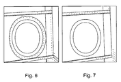
- Fig. 6 illustrates a view of the window system according to the prior art using a plurality of rivets, screws or fasteners for mounting the window frame to the skin of an aircraft.
- Fig. 7 illustrates an exemplary embodiment of the invention, where rivets, screws, fasteners and the like may be avoided for purposes of the force transfer between the window frame and the fibre metal laminate skin due to bonding of the window frame and the fibre metal laminate skin.
- the outer diameter of the mounting area of the window of the same size may be much lower when bonding the window frame and the fibre metal laminate skin, since an enlarged collar for receiving the rivets, fasteners, screws and the like is not necessary for mounting the window frame to the fibre metal laminate skin.
- Figs. 2, 3 , 4 and 5 are not scaled, but Figs. 6 and 7 are scaled.
- scope of the present invention also includes an aircraft having one or a plurality of inventive window systems.
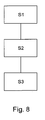
- Fig. 8 illustrates a flow diagram of a method according to the present invention.
- the method for mounting a window frame 20 and a fibre metal laminate skin 40 includes providing S 1 a fibre metal laminate skin 40 having a mounting surface portion 42, providing S2 a window frame 20 with a first flange 21, which first flange comprises a first side 23, wherein at least a part of a surface of the first side 23 is form-fitted to the mounting surface portion 42 of the fibre metal laminate skin 40, and bonding S3 at least a part of the surface of the first side 23 of the first flange 21 of the window frame 20 with a mounting surface portion 42 of the fibre metal laminate skin 40.
- S 1 and S2 may be also in a reversed order.
- the method according to an exemplary embodiment of the present invention may also be carried out, when being executed by a processor, by a programme element. Further, according to an exemplary embodiment, there is provided a computer-readable medium having stored thereon a programme element, which program element is adapted to carry out the inventive method.
- the present invention provides an improved design, an easier manufacturing, an improved lightning strike behaviour, a sufficient repairability, and better results in structural mechanical testing and analysis, a non-destructive inspection as well as full scale fatigue testing.
Landscapes
- Engineering & Computer Science (AREA)
- Mechanical Engineering (AREA)
- Aviation & Aerospace Engineering (AREA)
- Laminated Bodies (AREA)
Abstract
Description
- The present invention relates to a window system and a method for manufacturing a window system, and in particular to a window system, wherein a window frame is mounted on a fibre metal laminate skin of for example an aircraft, and a corresponding method for manufacturing the window system.
- Window belts in pressurized, metallic fuselages with mechanically fastened window frames are typical potential fatigue critical areas due to the reduction of a circumferential net section of the skin and stress concentrations caused by the presence of load transferring fasteners. The increasing demand for more passenger window view and increasing demand to save weight in airframe structures have driven the development of alternative structural solutions for the window frame environment. A stress analysis and strain gauge measurements on full scale tests have shown that mechanically fastened window frames environments are fatigue critical locations.
- It would be desirable to provide a window frame environment providing the possibility for more passenger window view and to save weight in airframe structures.
- The invention provides a window system overcoming the drawbacks of the prior art, an aircraft having a one or a plurality of said window systems, a corresponding method for manufacturing a window system, a corresponding programme element for carrying out the method, and a corresponding computer-readable medium.
- It should be noted that the following described exemplary embodiments of the invention apply also for the device, the method, the aircraft, the programme element and the computer-readable medium.
- According to an exemplary embodiment of the present invention, a window system comprises a fibre metal laminate skin having a mounting surface portion and a window frame having a first flange, which first flange comprises a first side, wherein at least a part of a surface of the first side is form-fitted to the mounting surface portion of the fibre metal laminate skin, and at least a part of the surface of the first side of the first flange and the mounting surface portion of the fibre metal laminate skin are bonded.
- A window system may be understood as a combination of a window frame, a mounting environment of the window frame on the skin, a mounting and corresponding elements.
- Fibre metal laminates may be a laminar compound of aluminium layers and glass fibre structures, in particular a glass fibre reinforced aluminium. However, it should be noted that fibre metal laminates may also include a carbon fibre structure or a blend of a carbon fibre and glass fibre structure as a reinforcement, or any other fibre being appropriate for reinforcement purposes. Further, fibre metal laminates may also include other metals, in particular light weight metals like titanium etc. It should be noted that fibre metal laminates may also be coated by other metals and materials, depending on the required purposes of the outer layer, for example with respect to environmental impact, which impacts may include climatic or weather impacts as well as impacts due to dust, forced impacts etc. A fibre metal laminate may also be a glare skin
- It should be noted that form-fitted means also any fitted structure, in which surfaces are fitted, irrespective whether the surfaces are curved or not. Thus, also two plane-fitted surfaces may be understood as form-fitted.
- It should be noted that bonding means also a laminary mounting by for example adhesive or solder or any other appropriate laminary fixation, wherein laminary should be understood as form-fitted. A bonding is therefore a fixation, in which the force transfer takes place via a face. Compared to a punctual fixation of a fastener, a rivet, a screw or the like, where the force transfer takes place via only the lateral cut of the fastener, rivet, the screw or the like, bonding allows to transfer the forces via the form-fitted faces of the two form-fitted elements.
- Bonded metallic window frames on metallic skins do not require any load carrying fasteners, therefore drastically reducing the amount of potential fatigue crack initiation locations in the skin and the window frame. A bonded structural connection is also characterized by a good damage tolerance behaviour.
- Bonding a mounting surface portion of a fibre metal laminate skin with a surface of a window frame further allows to more efficiently manufacture parts of aircrafts, in particular when the mounting process is also used for other manufacturing steps, so that when mounting a window frame to a fibre metal laminate skin by bonding, this mounting may share for example an autoclaving process step with other mounting by bonding processes, for example of doublers, skins, and stringers. Further, bonding a mounting surface portion of a fibre metal laminate skin with a surface of a window frame reduces the weight due to avoiding fasteners and flange portions which are adapted to be mounted with fasteners. Thus, the full advantage of bonding may be used by combining the bonding of components such as skins, doublers, window frames and stringers. In this way, the bonding technology is also a cost-effective way of manufacturing large fuselage shells. Both, the structural mechanic advantages as well as the cost reducing potential compared to mechanically fastened structures may be achieved by the subject-matter of the invention.
- According to an exemplary embodiment of the present invention, the first side of the first flange and the mounting surface of the fibre metal laminate skin sandwich a doubler, and the doubler is bonded to the first side of the first flange and the mounting surface of the fibre metal laminate skin. In other words, the bonding may take place also via an intermediate doubler.
- Thus, a reinforced structure may be provided by mounting a doubler reinforcement. Further, the doubler may also be adapted to constitute a form fitting intermediate or sandwiched layer. This may allow an improved equal distribution of forces as well as an improved form fitting.
- According to an exemplary embodiment of the invention, the first side of the first flange and the mounting surface of the fibre metal laminate skin are adhesively mounted.
- Thus, a sufficient mounting may be obtained, in particular, since modem adhesives allow a fast and efficient mounting, as well as a reliable connection between the elements.
- It should be noted, that with appropriate materials, also soldering or any other appropriate laminary fixation may be used for bonding a mounting surface portion of the fibre metal laminate skin and the surface of the first side of the first flange. Laminary mounted means a fixation in which the force transfer takes place via a face, compared to a punctual fixation of a fastener, a rivet, a screw or the like, where the force transfer takes place via only the lateral cut of the fastener, the rivet, the screw or the like.
- According to an exemplary embodiment of the invention, the first flange further comprises a second side, wherein a surface of the second side is inclined to the surface of the first side, so that the strength of the first flange substantially, continuously declines towards the edge of the first flange.
- Thus, it is possible to improve equal distribution of the forces and at the same time to reduce the weight of the window frame. Since no fasteners, screws or rivets are needed for mounting the window frame and the fibre metal laminate skin, no coplanar portions are required for the positioning of the fasteners, rivets or screws. Further, a reduced overlapping width may be achieved since no fasteners have to be used for mounting. No edge distance between the outer fasteners has to be maintained.
- According to an exemplary embodiment of the invention, the surface of the second side of the first flange smoothly transits to a surface being continued from the mounting surface portion of the fibre metal laminate skin.
- Thus, an optimum equal distribution of the forces can be achieved, as well as a smooth transit between the window frame and the fibre metal laminate skin. This may be of relevance when providing the transit in an environment of a high flow speed of the surrounding medium.
- According to an exemplary embodiment of the invention, the mounting surface of the fibre metal laminate skin corresponds to a surface facing the interior of an aircraft.
- Thus, it is possible to reduce the impact due to the pressure difference between the aircraft cabin and the outer area of the aircraft cabin, so that the interior overpressure presses the window frame onto the mounting surface, thus avoiding desolvation of a window frame from a fibre metal laminate skin due to the pressure difference.
- According to an exemplary embodiment of the invention, the first flange extents away from a window opening such that the flange radially extends into a plane.
- According to an exemplary embodiment of the invention, the first flange and the fibre metal laminate skin are conductively connected. The conductive connection may be at least one rivet, screw or fastener. Further, also a conductive adhesive may be provided allowing to conductively connect the fibre metal laminate skin and the window frame. Conductively connected means to be capable of a sufficiently fast potential equalization after e.g. lightning impact or other charges.
- A conductive connection between the window frame and the fibre metal laminate skin allows a sufficiently fast potential equalization due to lightning impact or other charges, so that any potential difference between the skin and the window frame may be avoided. Thus, sparks may be avoided between the window frame and the skin, thus reducing the ignition risk, damages on the surface due to surface discharges, which therefore increases the security for the passengers.
- According to an exemplary embodiment of the invention, the window frame further comprises a surface portion which substantially aligns with a surface portion of the fibre metal laminate skin. This surface portion may be provided on a separate flange, which flange may be embedded into the window opening of the skin.
- Thus, the outer surface of for example an aircraft may be uniformly designed in order to avoid flow resistance or turbulences due to a high velocity difference between the aircraft and the surrounding atmosphere during a flight.
- According to an exemplary embodiment of the invention, the fibre metal laminate skin is a fibre metal laminate fuselage skin of an aircraft.
- According to an exemplary embodiment of the invention, an aircraft comprises one or a plurality of window systems according to the invention.
- According to an exemplary embodiment of the invention, there is provided a method for mounting a window frame and a fibre metal laminate skin, which method includes providing a fibre metal laminate skin having a mounting surface portion, providing a window frame with a first flange, which first flange comprises a first side, wherein at least a part of a surface of the first side is form-fitted to the mounting surface portion of the fibre metal laminate skin, and bonding at least a part of the surface of the first side of the first flange of the window frame with the surface portion of the fibre metal laminate skin.
- According to an exemplary embodiment of the invention, there is provided a programme element, which, when being executed by a processor, is adapted to carry out the inventive method.
- According to an exemplary embodiment of the invention, there is provided a computer-readable medium having stored thereon an inventive program element.
- These and other aspects of the present invention will become apparent from and elucidated with reference to the embodiments described hereinafter.
- Exemplary embodiments of the present invention will be described in the following with reference to the following drawings.
-
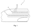
Fig. 1 illustrates a side view of an aircraft with a plurality of window belts. -
Fig. 2 illustrates a window system of the prior art. -
Fig. 3 illustrates a window system according to an exemplary embodiment of the invention. -
Fig. 4 illustrates a window system according to a further exemplary embodiment of the invention. -
Fig. 5 illustrates a window system according to a further exemplary embodiment of the invention. -
Fig. 6 illustrates a view of a window system of the prior art. -
Fig. 7 illustrates a window system according to an exemplary embodiment of the invention. -
Fig.8 illustrates an exemplary embodiment of the inventive method. - It should be noted that in the drawings, same reference numbers illustrate corresponding elements.
-
Fig. 1 illustrates a side view of anaircraft 1 having a plurality of window belts. Present developments include aircrafts having a plurality of passenger decks resulting in a plurality ofwindow belts 2, each comprising one or a plurality ofwindow systems 10. -
Fig. 2 illustrates awindow system 10 of the prior art. Thewindow system 10 of the prior art comprises awindow frame 20 and a fibremetal laminate skin 40, wherein thewindow frame 20 is fixably mounted on the fibremetal laminate skin 40 with aflange 21. The elements for mounting theflange 21 to the fibremetal laminate skin 40 may be for example rivets or fasteners (not shown) on thepositions 48. In order to provide an optimum force distribution at the fastener positions, it is necessary to provide coplanar surfaces on the upper side and the lower side of theflange 21, resulting in an either high material strength close to the edge of theflange 21 or to a steppedflange 21. -
Fig. 3 illustrates an exemplary embodiment of the invention of awindow system 10. Thewindow system 10 comprises awindow frame 20 and a fibremetal laminate skin 40, wherein the window frame comprises aflange 21 having twosides surface 42 of the fibremetal laminate skin 40. It should be noted that form-fitted means that at least a part of the surface of thefirst side 23 contacts the mountingsurface 42 of the fibremetal laminate skin 40 via an enlarged area.
In the illustrated embodiment ofFig. 3 , thewindow system 10 further comprises aflange 25 having asurface 26, which is designed such that thesurface 26 aligns with asurface 43 of the fibremetal laminate skin 40. In the exemplary embodiment ofFig. 3 , thesurface portions first surface 23 are directed to the exterior of an aircraft, wherein theflange 29, thesecond surface 22 offlange 21 and the mountingsurface 42 of the fibremetal laminate skin 40 are directed to the interior of an aircraft.
By aligning thesurfaces -
Fig. 4 illustrates a further exemplary embodiment of the present invention. -
Fig. 4 illustrates awindow system 10 having awindow frame 20. Thewindow frame 20 comprises aflange 21 having afirst surface 23 and asecond surface 22. Thefirst surface 23 is directed to the mountingsurface 42 of the fibremetal laminate skin 40. Between theflange 21 and the fibremetal laminate skin 40, there is provided adoubler 30. The doubler serves for strengthen the fibremetal laminate skin 40 in the area close to the edge, to which awindow frame 20 is provided. It should be noted that for this exemplary embodiment form-fitted means that thedoubler 30 is form-fitted to the mountingsurface 42 of the fibremetal laminate skin 40, as well as form-fitted to thefirst side 23 of thefirst flange 21 of thewindow frame 20. In other words, the doubler may also serve as a form-fitting intermediate layer. - The
window frame 20 further comprises asecond flange 25 having asurface 26. Thesurface 26 aligns with thesurface 43 of the fibremetal laminate skin 40 in order to constitute a smooth outer skin of an aircraft for minimizing turbulences and flow resistance. Thewindow frame 20 further comprises aflange 29 more or less directed towards the interior of an aircraft, wherein theflange 25 and theflange 29 may constitute a bearing for a window glass. - In the exemplary embodiment of
Fig. 4 , surfaces 26, 43 and 23 are directed to the exterior of an aircraft, wherein surfaces 22 and 42 are directed to the interior of an aircraft. It should be noted that it may be also possible to provide thedoubler 30 to the other side of the fibremetal laminate skin 40, where it is appropriate, e.g. for reinforcement purposes. - The
window frame 20 and the fibremetal laminate skin 40 may be electrically connected in order to avoid the build up of potential differences between thewindow frame 20 and the fibremetal laminate skin 40. The electrical conductivity may be achieved by means for example of a rivet, a fastener, a screw or the like, but may also be achieved by means of a conductive adhesive between thewindow frame 20 and the fibremetal laminate skin 40, in particular on theflange 21, and more particular between thefirst surface 23 of theflange 21 and at the mountingsurface 42 of the fibremetal laminate skin 40, irrespective whether they sandwich adoubler 30 or not. The doubler may be of aluminium or any other appropriate material. It should be noted that the rivet, the fastener, the screw or the like do not have to transfer force loads, and therefore, there is no necessity to providesurfaces surfaces flange 21 may be inclined to each other in order to find an optimum between the necessary material strength and the weight of the window frame. It should be noted that theflange 21 may be designed such that thesurface 22 smoothly transits to the surface, to which theflange 22 is mounted. Thus, no disturbing edges occur, and an optimum force transmission between the fibre metal laminate skin and the window frame is provided. Further, no recesses are present probably leading to a sedimentation of dust and dirt bearing the risk of corrosion and abrasion. - It should be noted that bonding may be any fixation being based on a lateral fixation in the meaning of adhering two surfaces. Bonding may be achieved for example by an adhesive, the selection of which is within the skilled knowledge, a soldering process where it is appropriate in view of the bonded materials, or a welding process, where it is appropriate with respect to the geometry.
- It should be noted that the provision of a rivet, a screw or a fastener or the like on the
position 45 does not require the presence of adoubler 30, but may be also provided in an exemplary embodiment as shown inFig. 3 . -
Fig. 5 illustrates a further exemplary embodiment of the present invention.Fig. 5 illustrates awindow system 10 comprising awindow frame 20 and a fibremetal laminate skin 40. In the embodiment according toFig. 5 , the window frame is mounted from the outside of an transport vehicle, e.g. an aircraft, a train or the like, wherein thesurfaces window frame 20 and theouter surface 23 of the fibremetal laminate skin 40, the fibre metal laminate skin may be slightly declined in the window frame region. Further, the window frame may be mounted with or without adoubler 30. Since the window system is not limited to the use in an aircraft, but may be also used in trains or ships, it may be possible to provide a window system capable of being resistant against a higher pressure from the outside of the vehicle. - It should be further noted that also the embodiment according to
Fig. 5 may comprise a conductive element for electrically connecting thewindow frame 20 to the fibremetal laminate skin 40. -
Fig. 6 illustrates a view of the window system according to the prior art using a plurality of rivets, screws or fasteners for mounting the window frame to the skin of an aircraft. To the contrary,Fig. 7 illustrates an exemplary embodiment of the invention, where rivets, screws, fasteners and the like may be avoided for purposes of the force transfer between the window frame and the fibre metal laminate skin due to bonding of the window frame and the fibre metal laminate skin. The outer diameter of the mounting area of the window of the same size may be much lower when bonding the window frame and the fibre metal laminate skin, since an enlarged collar for receiving the rivets, fasteners, screws and the like is not necessary for mounting the window frame to the fibre metal laminate skin. - It should be further noted that
Figs. 2, 3 ,4 and 5 are not scaled, butFigs. 6 and 7 are scaled. - Further, it should be noted that the scope of the present invention also includes an aircraft having one or a plurality of inventive window systems.
-
Fig. 8 illustrates a flow diagram of a method according to the present invention. The method for mounting awindow frame 20 and a fibremetal laminate skin 40 includes providing S 1 a fibremetal laminate skin 40 having a mountingsurface portion 42, providing S2 awindow frame 20 with afirst flange 21, which first flange comprises afirst side 23, wherein at least a part of a surface of thefirst side 23 is form-fitted to the mountingsurface portion 42 of the fibremetal laminate skin 40, and bonding S3 at least a part of the surface of thefirst side 23 of thefirst flange 21 of thewindow frame 20 with a mountingsurface portion 42 of the fibremetal laminate skin 40.S 1 and S2 may be also in a reversed order. - The method according to an exemplary embodiment of the present invention may also be carried out, when being executed by a processor, by a programme element. Further, according to an exemplary embodiment, there is provided a computer-readable medium having stored thereon a programme element, which program element is adapted to carry out the inventive method.
- The present invention provides an improved design, an easier manufacturing, an improved lightning strike behaviour, a sufficient repairability, and better results in structural mechanical testing and analysis, a non-destructive inspection as well as full scale fatigue testing.
- It should be noted that the term "comprising" does not exclude other elements or steps, and the "a" or "an" does not exclude a plurality. Also elements described in association with different embodiments may be combined.
- It should be noted that reference signs in the claims shall not be construed as limiting the scope of the claims.
Claims (15)
- Window system comprising
a fibre metal laminate skin (40) having a mounting surface portion(42); and
a window frame (20) having a first flange (21), which first flange comprises a first side (23), wherein at least a part of a surface of the first side is form-fitted to the mounting surface portion (42) of the fibre metal laminate skin (40);
wherein at least a part of the surface of the first side (23) of the first flange (21) and the mounting surface portion (42) of the fibre metal laminate skin (40) are bonded. - Window system of claim 1, wherein the first side (23) of the first flange (21) and the mounting surface (42) of the fibre metal laminate skin (40) sandwich a doubler (30), and the doubler is bonded to the first side (23) of the first flange (21) and the mounting surface (42) of the fibre metal laminate skin (40).
- Window system of claim 1, wherein the first side (23) of the first flange (21) and the mounting surface (42) of the fibre metal laminate skin (40) are adhesively mounted.
- Window system of claim 1, wherein the first flange (21) further comprises a second side (22), and a surface of the second side (22) is inclined to the surface of the first side (23), so that the strength of the first flange (21) substantially, continuously declines towards the edge of the first flange (21).
- Window system of claim 4, wherein the surface of the second side (22) smoothly transits to the surface (32, 42) to which the second side (22) is bonded.
- Window system of claim 1, wherein the mounting surface (42) of the fibre metal laminate skin (40) corresponds to a surface facing the interior of an aircraft. A 8938 / KK:AS:yb
- Window system of claim 1, wherein the first flange is an outer flange extending away from a window opening.
- Window system of claim 1, wherein the window frame (20) and the fibre metal laminate skin (40) are conductively connected.
- Window system of claim 8, wherein the window frame (20) and the fibre metal laminate skin (40) are conductively connected by at least one of the group of a rivet, a fastener and a screw(45).
- Window system of claim 1, wherein the window frame (20) further comprises a surface portion (26) which substantially aligns with a surface portion (43) of the fibre metal laminate skin (40).
- Window system of claim 1, wherein the fibre metal laminate skin (40) is a fibre metal laminate fuselage skin of an aircraft (1).
- Aircraft having one or a plurality of window systems (10) of any of claims 1 to 11.
- Method for mounting a window frame (20) and a fibre metal laminate skin (40), comprising:providing (S1) a fibre metal laminate skin (40) having a mounting surface portion (42);providing (S2) a window frame (20) with a first flange (21), which first flange comprises a first side (23), wherein at least a part of a surface of the first side (23) is form-fitted to the mounting surface portion (42) of the fibre metal laminate skin(40);bonding (S3) at least a part of the surface of the first side (23) of the first flange (21) of the window frame (20) with the mounting surface portion (42) of the fibre metal laminate skin (40).
- Programme element which, when being executed by a processor, is adapted to carry out the method of claim 13.
- Computer readable medium having stored thereon a programme element of claim 14.
Priority Applications (2)
| Application Number | Priority Date | Filing Date | Title |
|---|---|---|---|
| EP06026103.9A EP1932757B1 (en) | 2006-12-15 | 2006-12-15 | Bonded aluminium window frame on fibre metal laminate fuselage skin |
| US12/001,767 US20080172959A1 (en) | 2006-12-15 | 2007-12-12 | Bonded aluminum window frame on fibre metal laminate fuselage skin |
Applications Claiming Priority (1)
| Application Number | Priority Date | Filing Date | Title |
|---|---|---|---|
| EP06026103.9A EP1932757B1 (en) | 2006-12-15 | 2006-12-15 | Bonded aluminium window frame on fibre metal laminate fuselage skin |
Publications (2)
| Publication Number | Publication Date |
|---|---|
| EP1932757A1 true EP1932757A1 (en) | 2008-06-18 |
| EP1932757B1 EP1932757B1 (en) | 2016-10-26 |
Family
ID=37964306
Family Applications (1)
| Application Number | Title | Priority Date | Filing Date |
|---|---|---|---|
| EP06026103.9A Not-in-force EP1932757B1 (en) | 2006-12-15 | 2006-12-15 | Bonded aluminium window frame on fibre metal laminate fuselage skin |
Country Status (2)
| Country | Link |
|---|---|
| US (1) | US20080172959A1 (en) |
| EP (1) | EP1932757B1 (en) |
Cited By (1)
| Publication number | Priority date | Publication date | Assignee | Title |
|---|---|---|---|---|
| WO2012116918A1 (en) * | 2011-02-28 | 2012-09-07 | Airbus Operations Gmbh | Door frame construction, fuselage portion and aircraft or spacecraft |
Families Citing this family (9)
| Publication number | Priority date | Publication date | Assignee | Title |
|---|---|---|---|---|
| FR2933067B1 (en) * | 2008-06-26 | 2010-10-08 | Airbus France | REINFORCED AIRCRAFT FUSELAGE PANEL AND METHOD FOR MANUFACTURING THE SAME |
| CA2674768A1 (en) * | 2009-08-03 | 2011-02-03 | Prelco Inc. | Rigid glazing system using extrusion adherence |
| EP2640919A4 (en) | 2010-11-16 | 2018-01-10 | The Nordam Group, Inc. | Hybrid frame co-mold manufacture |
| JP5808111B2 (en) * | 2011-02-04 | 2015-11-10 | 三菱重工業株式会社 | Composite structure for aircraft, aircraft main wing and aircraft fuselage provided with the same |
| NL2007683C2 (en) * | 2011-10-31 | 2013-05-06 | Gtm Advanced Products B V | Improved fiber-metal laminate. |
| USD728446S1 (en) * | 2013-05-21 | 2015-05-05 | Airbus Corporate Jet Centre | Aircraft window |
| CN207072441U (en) * | 2017-07-28 | 2018-03-06 | 深圳市大疆创新科技有限公司 | The vision system and unmanned plane of unmanned plane |
| USD944986S1 (en) * | 2020-03-25 | 2022-03-01 | Seffiline S.R.L. | Surgical guide |
| FR3122519B1 (en) * | 2021-04-29 | 2026-03-13 | Saint Gobain | ACOUSTIC INSULATION DEVICE FOR AUTOMOTIVE GLAZING |
Citations (6)
| Publication number | Priority date | Publication date | Assignee | Title |
|---|---|---|---|---|
| US3061490A (en) * | 1959-09-23 | 1962-10-30 | Libbey Owens Ford Glass Co | Laminated safety glass |
| JPH1036139A (en) * | 1996-07-24 | 1998-02-10 | Mitsubishi Heavy Ind Ltd | Reinforced plate |
| EP1336469A1 (en) * | 2002-02-19 | 2003-08-20 | Alenia Aeronautica S.P.A. | Methods of manufacturing a stiffening element for an aircraft skin panel and a skin panel provided with the stiffening element |
| US20050247822A1 (en) * | 2004-05-10 | 2005-11-10 | Salmon James J | Load bearing window |
| WO2005115840A1 (en) * | 2004-05-24 | 2005-12-08 | Airbus Deutschland Gmbh | Window frame for aircraft |
| EP1647481A2 (en) * | 2004-10-15 | 2006-04-19 | Airbus Deutschland GmbH | Window element for an aircraft |
Family Cites Families (11)
| Publication number | Priority date | Publication date | Assignee | Title |
|---|---|---|---|---|
| US4310132A (en) * | 1978-02-16 | 1982-01-12 | Nasa | Fuselage structure using advanced technology fiber reinforced composites |
| US4495549A (en) * | 1982-09-28 | 1985-01-22 | The Boeing Company | Infrared radiation filter lens for aircraft lights |
| JPH0636977Y2 (en) * | 1988-01-30 | 1994-09-28 | 株式会社ニフコ | Adhesive wind molding installation device |
| US5277384A (en) * | 1991-11-04 | 1994-01-11 | Texstar, Inc. | Transparency quick seal system |
| DE19650416B4 (en) * | 1996-12-05 | 2004-10-07 | Airbus Deutschland Gmbh | Window for an airplane with a pressurized cabin |
| US6168112B1 (en) * | 1998-02-14 | 2001-01-02 | Daimlerchrysler Aerospace Airbus Gmbh | Double pane window for an aircraft cabin |
| US6648273B2 (en) * | 2001-10-30 | 2003-11-18 | The Boeing Company | Light weight and high strength fuselage |
| US6638075B2 (en) * | 2002-02-27 | 2003-10-28 | James R. Spaulding | Electrical connection to windshield/backglass |
| US6736352B2 (en) * | 2002-06-25 | 2004-05-18 | The Boeing Company | Aircraft windows and associated methods for installation |
| US20040035979A1 (en) * | 2002-08-23 | 2004-02-26 | Mccoskey William Robert | Integrally stiffened axial load carrying skin panels for primary aircraft structure and closed loop manufacturing methods for making the same |
| US20070056947A1 (en) * | 2005-09-15 | 2007-03-15 | Control Devices, Inc. | System and sensor for remote defrost activation |
-
2006
- 2006-12-15 EP EP06026103.9A patent/EP1932757B1/en not_active Not-in-force
-
2007
- 2007-12-12 US US12/001,767 patent/US20080172959A1/en not_active Abandoned
Patent Citations (6)
| Publication number | Priority date | Publication date | Assignee | Title |
|---|---|---|---|---|
| US3061490A (en) * | 1959-09-23 | 1962-10-30 | Libbey Owens Ford Glass Co | Laminated safety glass |
| JPH1036139A (en) * | 1996-07-24 | 1998-02-10 | Mitsubishi Heavy Ind Ltd | Reinforced plate |
| EP1336469A1 (en) * | 2002-02-19 | 2003-08-20 | Alenia Aeronautica S.P.A. | Methods of manufacturing a stiffening element for an aircraft skin panel and a skin panel provided with the stiffening element |
| US20050247822A1 (en) * | 2004-05-10 | 2005-11-10 | Salmon James J | Load bearing window |
| WO2005115840A1 (en) * | 2004-05-24 | 2005-12-08 | Airbus Deutschland Gmbh | Window frame for aircraft |
| EP1647481A2 (en) * | 2004-10-15 | 2006-04-19 | Airbus Deutschland GmbH | Window element for an aircraft |
Cited By (3)
| Publication number | Priority date | Publication date | Assignee | Title |
|---|---|---|---|---|
| WO2012116918A1 (en) * | 2011-02-28 | 2012-09-07 | Airbus Operations Gmbh | Door frame construction, fuselage portion and aircraft or spacecraft |
| CN103648907A (en) * | 2011-02-28 | 2014-03-19 | 空中客车营运有限公司 | Door frame construction, fuselage portion and aircraft or spacecraft |
| CN103648907B (en) * | 2011-02-28 | 2016-03-16 | 空中客车营运有限公司 | The fuselage sections of aircraft or spacecraft and doorframe structure |
Also Published As
| Publication number | Publication date |
|---|---|
| EP1932757B1 (en) | 2016-10-26 |
| US20080172959A1 (en) | 2008-07-24 |
Similar Documents
| Publication | Publication Date | Title |
|---|---|---|
| US20080172959A1 (en) | Bonded aluminum window frame on fibre metal laminate fuselage skin | |
| EP2117922B1 (en) | Compliant panel for aircraft | |
| US10611456B2 (en) | Aircraft with a drag neutral vehicle window | |
| JP6690910B2 (en) | COMPOSITE MATERIAL STRUCTURE HAVING JOINT OF COMPOSITE MATERIAL AND METAL, AND MANUFACTURING METHOD THEREOF | |
| US10093406B2 (en) | Aircraft frame for tailstrike angle enhancement | |
| US8333345B2 (en) | Composite aircraft joint | |
| US20090121081A1 (en) | Composite Bulkhead and Skin Construction | |
| US10228005B2 (en) | Fastener receptacle strip | |
| US20130306794A1 (en) | Aircraft structural assembly | |
| KR20150007202A (en) | Apparatus and methods for joining composite structures of aircrafts | |
| EP3243744B1 (en) | Aircraft joint | |
| US20100308172A1 (en) | Interconnection device connecting an aircraft internal structure component to the fuselage of this aircraft | |
| US20130236692A1 (en) | Composite material structure, and aircraft wing and aircraft fuselage provided therewith | |
| EP1750929A1 (en) | Structural panels for use in aircraft fuselages and other structures | |
| WO2014183611A1 (en) | Civil aircraft window body transparent element fastening structure and fastening method therefor | |
| US11312507B2 (en) | Repair assembly to repair an area on a member of a vehicle | |
| US8317130B1 (en) | Landing gear mount | |
| US20200023933A1 (en) | Pressure bulkhead and method of installation | |
| EP3257754A1 (en) | Lightning strike dispersion for composite aircraft structures | |
| CN111038681A (en) | Aircraft assembly | |
| EP3418181A1 (en) | Panel for an aircraft structure | |
| US20200180748A1 (en) | Foreign object impact proof windshield assembly | |
| US20230286637A1 (en) | Vehicle window assembly | |
| Werfelman | The composite evolution | |
| EP4640566A1 (en) | A rotary-wing aircraft with at least one attachment interface |
Legal Events
| Date | Code | Title | Description |
|---|---|---|---|
| PUAI | Public reference made under article 153(3) epc to a published international application that has entered the european phase |
Free format text: ORIGINAL CODE: 0009012 |
|
| AK | Designated contracting states |
Kind code of ref document: A1 Designated state(s): AT BE BG CH CY CZ DE DK EE ES FI FR GB GR HU IE IS IT LI LT LU LV MC NL PL PT RO SE SI SK TR |
|
| AX | Request for extension of the european patent |
Extension state: AL BA HR MK RS |
|
| 17P | Request for examination filed |
Effective date: 20081112 |
|
| AKX | Designation fees paid |
Designated state(s): AT BE BG CH CY CZ DE DK EE ES FI FR GB GR HU IE IS IT LI LT LU LV MC NL PL PT RO SE SI SK TR |
|
| 17Q | First examination report despatched |
Effective date: 20110629 |
|
| GRAP | Despatch of communication of intention to grant a patent |
Free format text: ORIGINAL CODE: EPIDOSNIGR1 |
|
| INTG | Intention to grant announced |
Effective date: 20160520 |
|
| GRAS | Grant fee paid |
Free format text: ORIGINAL CODE: EPIDOSNIGR3 |
|
| GRAA | (expected) grant |
Free format text: ORIGINAL CODE: 0009210 |
|
| AK | Designated contracting states |
Kind code of ref document: B1 Designated state(s): AT BE BG CH CY CZ DE DK EE ES FI FR GB GR HU IE IS IT LI LT LU LV MC NL PL PT RO SE SI SK TR |
|
| REG | Reference to a national code |
Ref country code: GB Ref legal event code: FG4D |
|
| REG | Reference to a national code |
Ref country code: CH Ref legal event code: EP |
|
| REG | Reference to a national code |
Ref country code: AT Ref legal event code: REF Ref document number: 839799 Country of ref document: AT Kind code of ref document: T Effective date: 20161115 |
|
| REG | Reference to a national code |
Ref country code: IE Ref legal event code: FG4D |
|
| REG | Reference to a national code |
Ref country code: DE Ref legal event code: R096 Ref document number: 602006050680 Country of ref document: DE |
|
| REG | Reference to a national code |
Ref country code: FR Ref legal event code: PLFP Year of fee payment: 11 |
|
| PGFP | Annual fee paid to national office [announced via postgrant information from national office to epo] |
Ref country code: DE Payment date: 20161213 Year of fee payment: 11 Ref country code: GB Payment date: 20161222 Year of fee payment: 11 |
|
| REG | Reference to a national code |
Ref country code: LT Ref legal event code: MG4D |
|
| PG25 | Lapsed in a contracting state [announced via postgrant information from national office to epo] |
Ref country code: LV Free format text: LAPSE BECAUSE OF FAILURE TO SUBMIT A TRANSLATION OF THE DESCRIPTION OR TO PAY THE FEE WITHIN THE PRESCRIBED TIME-LIMIT Effective date: 20161026 |
|
| PGFP | Annual fee paid to national office [announced via postgrant information from national office to epo] |
Ref country code: FR Payment date: 20161222 Year of fee payment: 11 |
|
| REG | Reference to a national code |
Ref country code: NL Ref legal event code: MP Effective date: 20161026 |
|
| REG | Reference to a national code |
Ref country code: AT Ref legal event code: MK05 Ref document number: 839799 Country of ref document: AT Kind code of ref document: T Effective date: 20161026 |
|
| PG25 | Lapsed in a contracting state [announced via postgrant information from national office to epo] |
Ref country code: LT Free format text: LAPSE BECAUSE OF FAILURE TO SUBMIT A TRANSLATION OF THE DESCRIPTION OR TO PAY THE FEE WITHIN THE PRESCRIBED TIME-LIMIT Effective date: 20161026 Ref country code: GR Free format text: LAPSE BECAUSE OF FAILURE TO SUBMIT A TRANSLATION OF THE DESCRIPTION OR TO PAY THE FEE WITHIN THE PRESCRIBED TIME-LIMIT Effective date: 20170127 Ref country code: SE Free format text: LAPSE BECAUSE OF FAILURE TO SUBMIT A TRANSLATION OF THE DESCRIPTION OR TO PAY THE FEE WITHIN THE PRESCRIBED TIME-LIMIT Effective date: 20161026 |
|
| PG25 | Lapsed in a contracting state [announced via postgrant information from national office to epo] |
Ref country code: ES Free format text: LAPSE BECAUSE OF FAILURE TO SUBMIT A TRANSLATION OF THE DESCRIPTION OR TO PAY THE FEE WITHIN THE PRESCRIBED TIME-LIMIT Effective date: 20161026 Ref country code: BE Free format text: LAPSE BECAUSE OF FAILURE TO SUBMIT A TRANSLATION OF THE DESCRIPTION OR TO PAY THE FEE WITHIN THE PRESCRIBED TIME-LIMIT Effective date: 20161026 Ref country code: AT Free format text: LAPSE BECAUSE OF FAILURE TO SUBMIT A TRANSLATION OF THE DESCRIPTION OR TO PAY THE FEE WITHIN THE PRESCRIBED TIME-LIMIT Effective date: 20161026 Ref country code: PT Free format text: LAPSE BECAUSE OF FAILURE TO SUBMIT A TRANSLATION OF THE DESCRIPTION OR TO PAY THE FEE WITHIN THE PRESCRIBED TIME-LIMIT Effective date: 20170227 Ref country code: PL Free format text: LAPSE BECAUSE OF FAILURE TO SUBMIT A TRANSLATION OF THE DESCRIPTION OR TO PAY THE FEE WITHIN THE PRESCRIBED TIME-LIMIT Effective date: 20161026 Ref country code: NL Free format text: LAPSE BECAUSE OF FAILURE TO SUBMIT A TRANSLATION OF THE DESCRIPTION OR TO PAY THE FEE WITHIN THE PRESCRIBED TIME-LIMIT Effective date: 20161026 Ref country code: IS Free format text: LAPSE BECAUSE OF FAILURE TO SUBMIT A TRANSLATION OF THE DESCRIPTION OR TO PAY THE FEE WITHIN THE PRESCRIBED TIME-LIMIT Effective date: 20170226 Ref country code: FI Free format text: LAPSE BECAUSE OF FAILURE TO SUBMIT A TRANSLATION OF THE DESCRIPTION OR TO PAY THE FEE WITHIN THE PRESCRIBED TIME-LIMIT Effective date: 20161026 |
|
| REG | Reference to a national code |
Ref country code: DE Ref legal event code: R097 Ref document number: 602006050680 Country of ref document: DE |
|
| PG25 | Lapsed in a contracting state [announced via postgrant information from national office to epo] |
Ref country code: CZ Free format text: LAPSE BECAUSE OF FAILURE TO SUBMIT A TRANSLATION OF THE DESCRIPTION OR TO PAY THE FEE WITHIN THE PRESCRIBED TIME-LIMIT Effective date: 20161026 Ref country code: RO Free format text: LAPSE BECAUSE OF FAILURE TO SUBMIT A TRANSLATION OF THE DESCRIPTION OR TO PAY THE FEE WITHIN THE PRESCRIBED TIME-LIMIT Effective date: 20161026 Ref country code: SK Free format text: LAPSE BECAUSE OF FAILURE TO SUBMIT A TRANSLATION OF THE DESCRIPTION OR TO PAY THE FEE WITHIN THE PRESCRIBED TIME-LIMIT Effective date: 20161026 Ref country code: EE Free format text: LAPSE BECAUSE OF FAILURE TO SUBMIT A TRANSLATION OF THE DESCRIPTION OR TO PAY THE FEE WITHIN THE PRESCRIBED TIME-LIMIT Effective date: 20161026 Ref country code: DK Free format text: LAPSE BECAUSE OF FAILURE TO SUBMIT A TRANSLATION OF THE DESCRIPTION OR TO PAY THE FEE WITHIN THE PRESCRIBED TIME-LIMIT Effective date: 20161026 |
|
| REG | Reference to a national code |
Ref country code: CH Ref legal event code: PL |
|
| PG25 | Lapsed in a contracting state [announced via postgrant information from national office to epo] |
Ref country code: BG Free format text: LAPSE BECAUSE OF FAILURE TO SUBMIT A TRANSLATION OF THE DESCRIPTION OR TO PAY THE FEE WITHIN THE PRESCRIBED TIME-LIMIT Effective date: 20170126 Ref country code: IT Free format text: LAPSE BECAUSE OF FAILURE TO SUBMIT A TRANSLATION OF THE DESCRIPTION OR TO PAY THE FEE WITHIN THE PRESCRIBED TIME-LIMIT Effective date: 20161026 |
|
| PLBE | No opposition filed within time limit |
Free format text: ORIGINAL CODE: 0009261 |
|
| STAA | Information on the status of an ep patent application or granted ep patent |
Free format text: STATUS: NO OPPOSITION FILED WITHIN TIME LIMIT |
|
| PG25 | Lapsed in a contracting state [announced via postgrant information from national office to epo] |
Ref country code: MC Free format text: LAPSE BECAUSE OF FAILURE TO SUBMIT A TRANSLATION OF THE DESCRIPTION OR TO PAY THE FEE WITHIN THE PRESCRIBED TIME-LIMIT Effective date: 20161026 |
|
| 26N | No opposition filed |
Effective date: 20170727 |
|
| REG | Reference to a national code |
Ref country code: IE Ref legal event code: MM4A |
|
| PG25 | Lapsed in a contracting state [announced via postgrant information from national office to epo] |
Ref country code: LI Free format text: LAPSE BECAUSE OF NON-PAYMENT OF DUE FEES Effective date: 20161231 Ref country code: CH Free format text: LAPSE BECAUSE OF NON-PAYMENT OF DUE FEES Effective date: 20161231 Ref country code: LU Free format text: LAPSE BECAUSE OF NON-PAYMENT OF DUE FEES Effective date: 20161215 |
|
| PG25 | Lapsed in a contracting state [announced via postgrant information from national office to epo] |
Ref country code: IE Free format text: LAPSE BECAUSE OF NON-PAYMENT OF DUE FEES Effective date: 20161215 Ref country code: SI Free format text: LAPSE BECAUSE OF FAILURE TO SUBMIT A TRANSLATION OF THE DESCRIPTION OR TO PAY THE FEE WITHIN THE PRESCRIBED TIME-LIMIT Effective date: 20161026 |
|
| PG25 | Lapsed in a contracting state [announced via postgrant information from national office to epo] |
Ref country code: HU Free format text: LAPSE BECAUSE OF FAILURE TO SUBMIT A TRANSLATION OF THE DESCRIPTION OR TO PAY THE FEE WITHIN THE PRESCRIBED TIME-LIMIT; INVALID AB INITIO Effective date: 20061215 Ref country code: CY Free format text: LAPSE BECAUSE OF FAILURE TO SUBMIT A TRANSLATION OF THE DESCRIPTION OR TO PAY THE FEE WITHIN THE PRESCRIBED TIME-LIMIT Effective date: 20161026 |
|
| PG25 | Lapsed in a contracting state [announced via postgrant information from national office to epo] |
Ref country code: TR Free format text: LAPSE BECAUSE OF FAILURE TO SUBMIT A TRANSLATION OF THE DESCRIPTION OR TO PAY THE FEE WITHIN THE PRESCRIBED TIME-LIMIT Effective date: 20161026 |
|
| REG | Reference to a national code |
Ref country code: DE Ref legal event code: R119 Ref document number: 602006050680 Country of ref document: DE |
|
| GBPC | Gb: european patent ceased through non-payment of renewal fee |
Effective date: 20171215 |
|
| REG | Reference to a national code |
Ref country code: FR Ref legal event code: ST Effective date: 20180831 |
|
| PG25 | Lapsed in a contracting state [announced via postgrant information from national office to epo] |
Ref country code: FR Free format text: LAPSE BECAUSE OF NON-PAYMENT OF DUE FEES Effective date: 20180102 Ref country code: DE Free format text: LAPSE BECAUSE OF NON-PAYMENT OF DUE FEES Effective date: 20180703 |
|
| PG25 | Lapsed in a contracting state [announced via postgrant information from national office to epo] |
Ref country code: GB Free format text: LAPSE BECAUSE OF NON-PAYMENT OF DUE FEES Effective date: 20171215 |