EP1932723A1 - Combination type cargo screen movable in a front and a rear direction - Google Patents
Combination type cargo screen movable in a front and a rear direction Download PDFInfo
- Publication number
- EP1932723A1 EP1932723A1 EP07106740A EP07106740A EP1932723A1 EP 1932723 A1 EP1932723 A1 EP 1932723A1 EP 07106740 A EP07106740 A EP 07106740A EP 07106740 A EP07106740 A EP 07106740A EP 1932723 A1 EP1932723 A1 EP 1932723A1
- Authority
- EP
- European Patent Office
- Prior art keywords
- main body
- screen
- lever
- rail part
- combination type
- Prior art date
- Legal status (The legal status is an assumption and is not a legal conclusion. Google has not performed a legal analysis and makes no representation as to the accuracy of the status listed.)
- Granted
Links
- 230000004888 barrier function Effects 0.000 claims abstract description 14
- 238000003780 insertion Methods 0.000 claims description 13
- 230000037431 insertion Effects 0.000 claims description 13
- 229910000831 Steel Inorganic materials 0.000 claims description 4
- 239000010959 steel Substances 0.000 claims description 4
- 230000009545 invasion Effects 0.000 description 6
- 230000002265 prevention Effects 0.000 description 6
- 238000009434 installation Methods 0.000 description 1
- 238000000034 method Methods 0.000 description 1
- 238000012986 modification Methods 0.000 description 1
- 230000004048 modification Effects 0.000 description 1
- 230000001105 regulatory effect Effects 0.000 description 1
Images

Classifications
-
- B—PERFORMING OPERATIONS; TRANSPORTING
- B60—VEHICLES IN GENERAL
- B60R—VEHICLES, VEHICLE FITTINGS, OR VEHICLE PARTS, NOT OTHERWISE PROVIDED FOR
- B60R5/00—Compartments within vehicle body primarily intended or sufficiently spacious for trunks, suit-cases, or the like
- B60R5/04—Compartments within vehicle body primarily intended or sufficiently spacious for trunks, suit-cases, or the like arranged at rear of vehicle
- B60R5/044—Compartments within vehicle body primarily intended or sufficiently spacious for trunks, suit-cases, or the like arranged at rear of vehicle luggage covering means, e.g. parcel shelves
- B60R5/045—Compartments within vehicle body primarily intended or sufficiently spacious for trunks, suit-cases, or the like arranged at rear of vehicle luggage covering means, e.g. parcel shelves collapsible or transformable
-
- B—PERFORMING OPERATIONS; TRANSPORTING
- B60—VEHICLES IN GENERAL
- B60R—VEHICLES, VEHICLE FITTINGS, OR VEHICLE PARTS, NOT OTHERWISE PROVIDED FOR
- B60R21/00—Arrangements or fittings on vehicles for protecting or preventing injuries to occupants or pedestrians in case of accidents or other traffic risks
- B60R21/02—Occupant safety arrangements or fittings, e.g. crash pads
- B60R21/06—Safety nets, transparent sheets, curtains, or the like, e.g. between occupants and glass
-
- B—PERFORMING OPERATIONS; TRANSPORTING
- B60—VEHICLES IN GENERAL
- B60R—VEHICLES, VEHICLE FITTINGS, OR VEHICLE PARTS, NOT OTHERWISE PROVIDED FOR
- B60R5/00—Compartments within vehicle body primarily intended or sufficiently spacious for trunks, suit-cases, or the like
- B60R5/04—Compartments within vehicle body primarily intended or sufficiently spacious for trunks, suit-cases, or the like arranged at rear of vehicle
- B60R5/044—Compartments within vehicle body primarily intended or sufficiently spacious for trunks, suit-cases, or the like arranged at rear of vehicle luggage covering means, e.g. parcel shelves
- B60R5/045—Compartments within vehicle body primarily intended or sufficiently spacious for trunks, suit-cases, or the like arranged at rear of vehicle luggage covering means, e.g. parcel shelves collapsible or transformable
- B60R5/047—Compartments within vehicle body primarily intended or sufficiently spacious for trunks, suit-cases, or the like arranged at rear of vehicle luggage covering means, e.g. parcel shelves collapsible or transformable collapsible by rolling-up
-
- B—PERFORMING OPERATIONS; TRANSPORTING
- B60—VEHICLES IN GENERAL
- B60R—VEHICLES, VEHICLE FITTINGS, OR VEHICLE PARTS, NOT OTHERWISE PROVIDED FOR
- B60R11/00—Arrangements for holding or mounting articles, not otherwise provided for
- B60R2011/0001—Arrangements for holding or mounting articles, not otherwise provided for characterised by position
- B60R2011/0003—Arrangements for holding or mounting articles, not otherwise provided for characterised by position inside the vehicle
- B60R2011/0036—Luggage compartment
-
- B—PERFORMING OPERATIONS; TRANSPORTING
- B60—VEHICLES IN GENERAL
- B60R—VEHICLES, VEHICLE FITTINGS, OR VEHICLE PARTS, NOT OTHERWISE PROVIDED FOR
- B60R11/00—Arrangements for holding or mounting articles, not otherwise provided for
- B60R2011/0042—Arrangements for holding or mounting articles, not otherwise provided for characterised by mounting means
- B60R2011/0049—Arrangements for holding or mounting articles, not otherwise provided for characterised by mounting means for non integrated articles
- B60R2011/005—Connection with the vehicle part
-
- B—PERFORMING OPERATIONS; TRANSPORTING
- B60—VEHICLES IN GENERAL
- B60R—VEHICLES, VEHICLE FITTINGS, OR VEHICLE PARTS, NOT OTHERWISE PROVIDED FOR
- B60R11/00—Arrangements for holding or mounting articles, not otherwise provided for
- B60R2011/0042—Arrangements for holding or mounting articles, not otherwise provided for characterised by mounting means
- B60R2011/008—Adjustable or movable supports
Definitions
- the present invention relates to a combination type cargo screen movable front and rear, and more particularly to a combination type cargo screen in which a main body supporting a cover screen can move in a forward and a rearward direction of a vehicle so as to enhance convenience of use and to which a barrier net for satisfying regulations of luggage invasion prevention can be adopted.
- a recreational vehicle is generally provided with a luggage room between a rear seat and a rear door, and in order to prevent luggage contained in the luggage room from being exposed or to fix the luggage, a cargo screen is provided.
- the cargo screen is comprised of a cover screen coveting luggage and a main body to which the cover screen is rolled.
- the cover screen is exploded to be used in a state that the main body supporting the cover screen is fixed to the luggage room.
- a combination type cargo screen which adopts a barrier bet to the cargo screen so as to separate the luggage room and the passenger room is also used.
- the combination type cargo screen should pass luggage invasion prevention test.
- the main body is fixed to the luggage room.
- the present invention has been made in an effort to provide a combination type cargo screen movable front and rear in which a main body supporting a cover screen is movable in a forward and a rearward direction of a vehicle so as to enhance convenience of use and to which a barrier net for satisfying regulations on luggage invasion prevention can be adopted.
- An exemplary embodiment of the present invention provides a combination type cargo screen movable front and rear including: a main body which is mounted to a luggage room of a vehicle and can separably mount a barrier net which is prevents luggage from invading into a passenger room is connected; a cover screen which is rolled around the main body and can be drawn so as to cover luggage contained in the luggage room and wherein the screen moving device which moves the main body in a forward and a rear direction of the vehicle includes guide parts which are mounted to both sides of the luggage room along a drawing-out direction of the cover screen, a fixing rail part which is fixed along a length direction of the guide part and is provided with a plurality of gear teeth, an operation lever part which is movably mounted on an upper surface of the fixing rail part and moves in a length direction of the fixing rail part by a manipulation of a user, and a moving rail part which is coupled to an upper part of the operation lever part so as to house an end of the main body, moves along a length direction of the fixing rail part by the operation
- the operation lever part may include: a lever body with a shape of a long rod; a lever which is protruded at one end of the lever body so as to be able to be pushed or pulled by a user; and a roller which is rotatably connected to the other end of the lever body and moved along the fixing rail part.
- the roller may further include a plurality of gear teeth which are engaged with the gear teeth of the fixing rail part and the moving rail part.
- the gear teeth of the moving rail part may be formed toward an upper surface of the lever body, and the moving rail part may further include a body receiving part which houses an end of the main body at an end thereof which is adjacent to the roller.
- the main body may further include a guide pin which is protruded at both ends thereof, and the guide part further include an insertion part which is formed at an initial mount position where the cover screen is not drawn out so as to house the guide pin.
- the main body may further include a hook which is installed to lower surfaces of both ends and a hook lever which protrudes and returns the hook
- the guide part may further include a hooking part which is formed to be adjacent to the insertion part and to which the hook lever is maintained to be hooked.
- a steel bracket supporting an upper side and a lower side of the guide pin at an insertion state of the guide pin may be provided at an inside of the insertion part.
- a moving distance of the main body may be set at twice of a moving distance of the lever.
- vehicle 10 luggage room 100: cargo screen 120: barrier net 130: cover screen 200: screen moving device 210: guide part 220: fixing rail part 230: operation lever part 240: moving rail part
- FIG. 1 is a partial perspective view showing a vehicle to which a cargo screen according to an exemplary embodiment of the present invention is mounted
- FIG. 2 is a perspective view showing a mounting position according to a cargo screen according to an exemplary embodiment of the present invention
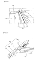
- FIG. 3 is a partial perspective view of a cargo screen and a screen moving device according to an exemplary embodiment of the present invention
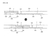
- FIG. 4 is a side view showing an operation state of a screen moving device according to an exemplary embodiment of the present invention
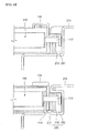
- FIG. 5 is a horizontal cross sectional view showing an end part of a body and a guide part according to a cargo screen according to an exemplary embodiment of the present invention.
- a combination type cargo screen 100 is mounted to a luggage room 10 of a vehicle 1 to cover things contained in the luggage room 10.
- the combination type cargo screen 100 is a type to which a barrier net 120 which isolates a passenger room from the luggage room 10 to enhance the safety of a passenger can be connected.
- a cargo screen 100 can move in a front and a rear direction of the vehicle 1 by a screen moving device 200 so as to enhance convenience of a passenger.
- the combination type cargo screen 100 includes a main body 110 which is disposed in a width direction of the luggage room 10, the barrier net 120 which is separably mounted at an upper part of the main body 110, and a cover screen 130 which is winded around the main body 110 and can be drawn to cover luggage.
- both ends of the main body 110 are separably housed in a moving rail part 240.
- a guide pin 112 and a hook 114 are provided at both ends of the main body 110, and a hook lever 116 for operating the hook 114 is provided.
- the hooks 114 are respectively provided at lower sides of both ends of the main body 110, and are downwardly protruded below the main body 110 by the hook lever 116 or return to their original position.
- the cargo screen 100 When the cargo screen 100 is not used in a state in that the main body 110 is inserted into the moving rail part 240, the cargo screen 100 should be fixed to an initial mount position A. The reason of this is to firmly fix the barrier net 120 thereby satisfying the regulation regarding prevention of luggage invasion.
- the guide pin 112 is inserted into a guide part 210, so the main body 110 of the cargo screen 100 is firstly fixed to the initial mount position A. Then, the hook lever 116 is operated so that the hook 114 is hooked by a hooking part 214, thereby secondly fixing the main body 110. Further detailed explanation for the same will be made later.
- the main body 110 of the cargo screen 100 can freely move between positions where the cover screen 130 is not used, that is, between the initial mount position A and an operation position B by the screen moving device 200, and can be fixed.
- the screen moving device 200 includes the guide parts 210 which are mounted to both sides of the luggage room 10, a fixing rail part 220 which is fixed to the guide part 210, an operation lever part 230 which is movably mounted to an upper surface of the fixing rail part 220, and the moving rail part 240 which is coupled to an upper part of the operation lever part 230.
- the guide part 210 is bent in a shape of ' ⁇ ', and then is again inwardly bent so as to have a structure housing the fixing rail part 220, the operation lever part 230, and the moving rail part 240.
- the fixing rail part 220 having a plurality of gear teeth P is disposed on a bottom surface of the guide part 210.
- An insertion part 212 and a steel bracket 216 housing the guide pin 112 which is formed to the main body 110 is formed at an end of the guide part 210.
- the hooking part 214 to which the hook 114 which is formed to the main body 110 in the vicinity of the insertion part 212 is maintained to be hooked thereto is formed in an inside of the guide part 210.
- the insertion part 212 has a shape responding to a shape of the guide pin 112, and serves to house the guide pin 112 so as to firstly fix the main body 110.
- the insertion part 212 is preferably formed at a position corresponding to a position for use of the barrier net 120, that is, the initial mount position A.
- the steel bracket 216 serves to support the guide pin 112 which is housed by the insertion part 212 at an upper side and a lower side.
- the hooking part 214 is formed along a length direction of the guide part 210, and the hook 114 is hooked to the hooking part 214 at the initial mount position A.
- the hook lever 116 is operated to separate the hook 114 from the hooking part 214.
- the fixing rail part 220 has a length corresponding to a length from the initial mount position A of the cargo screen 100 the operation position B where can be easily used by a user.
- the operation position B can be varied according to a size of the luggage room 10, or the like.
- the operation lever part 230 is installed to an upper part of the fixing rail part 220.
- the operation lever part 230 includes a lever body 232 with a shape of a long rod, a lever 234 which is protruded at one end of the lever body 232 so as to be able to be pushed or pulled by a user, and a roller 236 which is rotatably connected to the other end of the lever body 232 and moves along the fixing rail part 220.
- a plurality of gear teeth P which are engaged with the gear teeth formed to the fixing rail part 220 and the moving rail part 240 are formed on an outer circumference of the roller 236.
- the moving rail part 240 is disposed onto the operation lever part 230, and has a plurality of gear teeth P which are protruded toward an upper surface of the lever body 232.
- the gear teeth are formed to the moving rail part 240 to be adjacent to the roller 236, and a body receiving part 242 housing the main body 110 of the cargo screen 100 is formed.
- the roller 236 which is connected to the lever body 232 rotates toward the rear side of the vehicle 1 along the fixing rail part 220.
- the roller 236 rotates to pull the moving rail part 240 toward the rear side of the vehicle 1. Accordingly, the main body 110 of the cargo screen 100 which is housed by the moving rail part 240 moves toward the rear side of the vehicle.
- the main body 110 is positioned at the operation position B.
- a user can use the cargo screen 100 without getting in the luggage room 10 or putting his hand on a floor at the operation position B, so that convenience is enhanced.
- the moving distance of the main body 110 of the cargo screen 100 is set at twice of the moving distance of the lever 234. This can be regulated by varying the size and the distance of teeth P of the fixing rail part 220, the moving rail part 240, and the roller 236.
- the roller 236 rotates toward the front side of the vehicle 1 along the fixing rail part 220. While the roller 236 rotates, the roller 236 moves the moving rail part 240 toward the front side of the vehicle 1. Accordingly, the main body 110 of the cargo screen 100 which is housed in the moving rail part 240 moves toward the front side of the vehicle.
- the main body 110 is positioned at the initial mount position A.
- the cargo screen 100 can be used even at the initial mount position A, and at this position, the barrier net 120 is used.
- the barrier net 120 is used, the main body 110 is firmly fixed to the guide part 210, so that regulations on luggage invasion prevention can be satisfied.
- the main body supporting the cover screen can move in a forward and a rear ward direction of a vehicle, so that convenience of use is enhanced.
- the main body of the cargo screen can be returned to its initial installation position, so that regulations on luggage invasion prevention can be satisfied.
Landscapes
- Engineering & Computer Science (AREA)
- Mechanical Engineering (AREA)
- Vehicle Step Arrangements And Article Storage (AREA)
Abstract
Description
- This application claims priority to and the benefit of
Korean Patent Application No. 10-2006-0128896 - The present invention relates to a combination type cargo screen movable front and rear, and more particularly to a combination type cargo screen in which a main body supporting a cover screen can move in a forward and a rearward direction of a vehicle so as to enhance convenience of use and to which a barrier net for satisfying regulations of luggage invasion prevention can be adopted.
- A recreational vehicle is generally provided with a luggage room between a rear seat and a rear door, and in order to prevent luggage contained in the luggage room from being exposed or to fix the luggage, a cargo screen is provided.
- Generally, the cargo screen is comprised of a cover screen coveting luggage and a main body to which the cover screen is rolled. In case that the cargo screen needs to be used, the cover screen is exploded to be used in a state that the main body supporting the cover screen is fixed to the luggage room.
- Meanwhile, in order to enhance of the safety of a passenger, a combination type cargo screen which adopts a barrier bet to the cargo screen so as to separate the luggage room and the passenger room is also used.
- However, in European countries, the combination type cargo screen should pass luggage invasion prevention test. For this test, it is preferable that the main body is fixed to the luggage room.
- Accordingly, since the distance between the cargo screen and the rear end of the vehicle becomes great, there is a problem in that it is necessary for a user to enter the luggage room in order to use the cargo screen or to put his hand on a floor of the luggage room to pull out the cover screen.
- The present invention has been made in an effort to provide a combination type cargo screen movable front and rear in which a main body supporting a cover screen is movable in a forward and a rearward direction of a vehicle so as to enhance convenience of use and to which a barrier net for satisfying regulations on luggage invasion prevention can be adopted.
- An exemplary embodiment of the present invention provides a combination type cargo screen movable front and rear including: a main body which is mounted to a luggage room of a vehicle and can separably mount a barrier net which is prevents luggage from invading into a passenger room is connected; a cover screen which is rolled around the main body and can be drawn so as to cover luggage contained in the luggage room and wherein the screen moving device which moves the main body in a forward and a rear direction of the vehicle includes guide parts which are mounted to both sides of the luggage room along a drawing-out direction of the cover screen, a fixing rail part which is fixed along a length direction of the guide part and is provided with a plurality of gear teeth, an operation lever part which is movably mounted on an upper surface of the fixing rail part and moves in a length direction of the fixing rail part by a manipulation of a user, and a moving rail part which is coupled to an upper part of the operation lever part so as to house an end of the main body, moves along a length direction of the fixing rail part by the operation lever part, and is provided with a plurality of gear teeth.
- The operation lever part may include: a lever body with a shape of a long rod; a lever which is protruded at one end of the lever body so as to be able to be pushed or pulled by a user; and a roller which is rotatably connected to the other end of the lever body and moved along the fixing rail part.
- The roller may further include a plurality of gear teeth which are engaged with the gear teeth of the fixing rail part and the moving rail part.
- The gear teeth of the moving rail part may be formed toward an upper surface of the lever body, and the moving rail part may further include a body receiving part which houses an end of the main body at an end thereof which is adjacent to the roller.
- The main body may further include a guide pin which is protruded at both ends thereof, and the guide part further include an insertion part which is formed at an initial mount position where the cover screen is not drawn out so as to house the guide pin.
- The main body may further include a hook which is installed to lower surfaces of both ends and a hook lever which protrudes and returns the hook, and the guide part may further include a hooking part which is formed to be adjacent to the insertion part and to which the hook lever is maintained to be hooked.
- A steel bracket supporting an upper side and a lower side of the guide pin at an insertion state of the guide pin may be provided at an inside of the insertion part.
- A moving distance of the main body may be set at twice of a moving distance of the lever.
-
-
FIG. 1 is a partial perspective view showing a vehicle to which a cargo screen according to an exemplary embodiment of the present invention is mounted. -
FIG. 2 is a perspective view showing a mounting position according to a cargo screen according to an exemplary embodiment of the present invention. -
FIG. 3 is a partial perspective view of a cargo screen and a screen moving device according to an exemplary embodiment of the present invention. -
FIG. 4 is a side view showing an operation state of a screen moving device according to an exemplary embodiment of the present invention. -
FIG. 5 is a horizontal cross sectional view showing an end part of a body and a guide part according to a cargo screen according to an exemplary embodiment of the present invention. -
1: vehicle 10: luggage room 100: cargo screen 120: barrier net 130: cover screen 200: screen moving device 210: guide part 220: fixing rail part 230: operation lever part 240: moving rail part - An exemplary embodiment of the present invention will hereinafter be described in detail with reference to the accompanying drawings.
-
FIG. 1 is a partial perspective view showing a vehicle to which a cargo screen according to an exemplary embodiment of the present invention is mounted,FIG. 2 is a perspective view showing a mounting position according to a cargo screen according to an exemplary embodiment of the present invention,FIG. 3 is a partial perspective view of a cargo screen and a screen moving device according to an exemplary embodiment of the present invention,FIG. 4 is a side view showing an operation state of a screen moving device according to an exemplary embodiment of the present invention, andFIG. 5 is a horizontal cross sectional view showing an end part of a body and a guide part according to a cargo screen according to an exemplary embodiment of the present invention. - As shown in
FIG. 1 , a combinationtype cargo screen 100 according to an exemplary embodiment of the present invention is mounted to aluggage room 10 of avehicle 1 to cover things contained in theluggage room 10. - The combination
type cargo screen 100 according to an exemplary embodiment of the present invention is a type to which abarrier net 120 which isolates a passenger room from theluggage room 10 to enhance the safety of a passenger can be connected. Acargo screen 100 can move in a front and a rear direction of thevehicle 1 by ascreen moving device 200 so as to enhance convenience of a passenger. - As shown in
FIG. 1 to FIG. 5 , the combinationtype cargo screen 100 according to an exemplary embodiment of the present invention includes amain body 110 which is disposed in a width direction of theluggage room 10, thebarrier net 120 which is separably mounted at an upper part of themain body 110, and acover screen 130 which is winded around themain body 110 and can be drawn to cover luggage. - As shown in
FIG. 3 andFIG. 5 , both ends of themain body 110 are separably housed in a movingrail part 240. Aguide pin 112 and ahook 114 are provided at both ends of themain body 110, and ahook lever 116 for operating thehook 114 is provided. - The
hooks 114 are respectively provided at lower sides of both ends of themain body 110, and are downwardly protruded below themain body 110 by thehook lever 116 or return to their original position. - When the
cargo screen 100 is not used in a state in that themain body 110 is inserted into the movingrail part 240, thecargo screen 100 should be fixed to an initial mount position A. The reason of this is to firmly fix thebarrier net 120 thereby satisfying the regulation regarding prevention of luggage invasion. - For this, the
guide pin 112 is inserted into aguide part 210, so themain body 110 of thecargo screen 100 is firstly fixed to the initial mount position A. Then, thehook lever 116 is operated so that thehook 114 is hooked by a hookingpart 214, thereby secondly fixing themain body 110. Further detailed explanation for the same will be made later. - As shown in
FIG. 2 , themain body 110 of thecargo screen 100 can freely move between positions where thecover screen 130 is not used, that is, between the initial mount position A and an operation position B by thescreen moving device 200, and can be fixed. - As shown in
FIG. 3 to FIG. 5 , thescreen moving device 200 includes theguide parts 210 which are mounted to both sides of theluggage room 10, a fixingrail part 220 which is fixed to theguide part 210, anoperation lever part 230 which is movably mounted to an upper surface of the fixingrail part 220, and the movingrail part 240 which is coupled to an upper part of theoperation lever part 230. - As shown in
FIG. 3 andFIG. 4 , theguide part 210 is bent in a shape of '⊏', and then is again inwardly bent so as to have a structure housing the fixingrail part 220, theoperation lever part 230, and the movingrail part 240. - As shown in
FIG. 4 andFIG. 5 , the fixingrail part 220 having a plurality of gear teeth P is disposed on a bottom surface of theguide part 210. Aninsertion part 212 and asteel bracket 216 housing theguide pin 112 which is formed to themain body 110 is formed at an end of theguide part 210. The hookingpart 214 to which thehook 114 which is formed to themain body 110 in the vicinity of theinsertion part 212 is maintained to be hooked thereto is formed in an inside of theguide part 210. - The
insertion part 212 has a shape responding to a shape of theguide pin 112, and serves to house theguide pin 112 so as to firstly fix themain body 110. Theinsertion part 212 is preferably formed at a position corresponding to a position for use of thebarrier net 120, that is, the initial mount position A. - The
steel bracket 216 serves to support theguide pin 112 which is housed by theinsertion part 212 at an upper side and a lower side. - The hooking
part 214 is formed along a length direction of theguide part 210, and thehook 114 is hooked to the hookingpart 214 at the initial mount position A. In order to release fixing of themain body 110, thehook lever 116 is operated to separate thehook 114 from the hookingpart 214. - The fixing
rail part 220 has a length corresponding to a length from the initial mount position A of thecargo screen 100 the operation position B where can be easily used by a user. The operation position B can be varied according to a size of theluggage room 10, or the like. Theoperation lever part 230 is installed to an upper part of the fixingrail part 220. - As shown in
FIG. 3 andFIG. 4 , theoperation lever part 230 includes alever body 232 with a shape of a long rod, alever 234 which is protruded at one end of thelever body 232 so as to be able to be pushed or pulled by a user, and aroller 236 which is rotatably connected to the other end of thelever body 232 and moves along the fixingrail part 220. - A plurality of gear teeth P which are engaged with the gear teeth formed to the fixing
rail part 220 and the movingrail part 240 are formed on an outer circumference of theroller 236. - As shown in
FIG. 4 , the movingrail part 240 is disposed onto theoperation lever part 230, and has a plurality of gear teeth P which are protruded toward an upper surface of thelever body 232. The gear teeth are formed to the movingrail part 240 to be adjacent to theroller 236, and abody receiving part 242 housing themain body 110 of thecargo screen 100 is formed. - An operating process of a combination type cargo screen movable front and rear according to an exemplary embodiment of the present invention will be briefly explained hereinafter.
- If the
lever 234 is pulled by a user, theroller 236 which is connected to thelever body 232 rotates toward the rear side of thevehicle 1 along thefixing rail part 220. Theroller 236 rotates to pull the movingrail part 240 toward the rear side of thevehicle 1. Accordingly, themain body 110 of thecargo screen 100 which is housed by the movingrail part 240 moves toward the rear side of the vehicle. - At this time, the
main body 110 is positioned at the operation position B. A user can use thecargo screen 100 without getting in theluggage room 10 or putting his hand on a floor at the operation position B, so that convenience is enhanced. - For convenience of a user, it is preferable that the moving distance of the
main body 110 of thecargo screen 100 is set at twice of the moving distance of thelever 234. This can be regulated by varying the size and the distance of teeth P of the fixingrail part 220, the movingrail part 240, and theroller 236. - To the contrary, if a user pushes the
lever 234, theroller 236 rotates toward the front side of thevehicle 1 along the fixingrail part 220. While theroller 236 rotates, theroller 236 moves the movingrail part 240 toward the front side of thevehicle 1. Accordingly, themain body 110 of thecargo screen 100 which is housed in the movingrail part 240 moves toward the front side of the vehicle. - At this time, the
main body 110 is positioned at the initial mount position A. Thecargo screen 100 can be used even at the initial mount position A, and at this position, thebarrier net 120 is used. When thebarrier net 120 is used, themain body 110 is firmly fixed to theguide part 210, so that regulations on luggage invasion prevention can be satisfied. - While this invention has been described in connection with what is presently considered to be practical exemplary embodiments, it is to be understood that the invention is not limited to the disclosed embodiments, but, on the contrary, is intended to cover various modifications and equivalent arrangements included within the spirit and scope of the appended claims.
- As described above, in a combination type cargo screen movable front and rear according to an exemplary embodiment of the present invention, the main body supporting the cover screen can move in a forward and a rear ward direction of a vehicle, so that convenience of use is enhanced.
- Furthermore, in case that the barrier bet is adopted, the main body of the cargo screen can be returned to its initial installation position, so that regulations on luggage invasion prevention can be satisfied.
Claims (8)
- A combination type cargo screen movable front and rear comprising:a main body which is mounted to a luggage room of a vehicle and can separably mount a barrier net which is prevents luggage from invading into a passenger room is connected;a cover screen which is rolled around the main body and can be drawn so as to cover luggage contained in the luggage room; andwherein the screen moving device which moves the main body in a forward and a rear direction of the vehicle comprises guide parts which are mounted to both sides of the luggage room along a drawing-out direction of the cover screen, a fixing rail part which is fixed along a length direction of the guide part and is provided with a plurality of gear teeth, an operation lever part which is movably mounted on an upper surface of the fixing rail part and moves in a length direction of the fixing rail part by a manipulation of a user, and a moving rail part which is coupled to an upper part of the operation lever part so as to house an end of the main body, moves along a length direction of the fixing rail part by the operation lever part, and is provided with a plurality of gear teeth.
- The combination type cargo screen of claim 1, wherein the operation lever part comprises:a lever body with a shape of a long rod;a lever which is protruded at one end of the lever body so as to be able to be pushed or pulled by a user; anda roller which is rotatably connected to the other end of the lever body and moved along the fixing rail part.
- The combination type cargo screen of claim 2, wherein the roller further comprises a plurality of gear teeth which are engaged with the gear teeth of the fixing rail part and the moving rail part.
- The combination type cargo screen of claim 1, wherein the gear teeth of the moving rail part are formed toward an upper surface of the lever body and the moving rail part further comprises a body receiving part which houses an end of the main body at an end thereof which is adjacent to the roller.
- The combination type cargo screen of claim 1, wherein the main body further comprises a guide pin which is protruded at both ends thereof, and the guide part further comprises an insertion part which is formed at an initial mount position where the cover screen is not drawn out so as to house the guide pin.
- The combination type cargo screen of claim 5, wherein the main body further comprises a hook which is installed to lower surfaces of both ends and a hook lever which protrudes and returns the hook, and the guide part further comprises a hooking part which is formed to be adjacent to the insertion part and to which the hook lever is maintained to be hooked.
- The combination type cargo screen of claim 5, wherein a steel bracket supporting an upper side and a lower side of the guide pin at an insertion state of the guide pin is provided at an inside of the insertion part.
- The combination type cargo screen of one of claim 1 to claim 7, wherein a moving distance of the main body is set at twice of a moving distance of the lever.
Applications Claiming Priority (1)
| Application Number | Priority Date | Filing Date | Title |
|---|---|---|---|
| KR1020060128896A KR100794025B1 (en) | 2006-12-15 | 2006-12-15 | Combination type cargo screen which can move back and forth |
Publications (2)
| Publication Number | Publication Date |
|---|---|
| EP1932723A1 true EP1932723A1 (en) | 2008-06-18 |
| EP1932723B1 EP1932723B1 (en) | 2010-01-06 |
Family
ID=39199382
Family Applications (1)
| Application Number | Title | Priority Date | Filing Date |
|---|---|---|---|
| EP07106740A Ceased EP1932723B1 (en) | 2006-12-15 | 2007-04-23 | Combination type cargo screen movable in a front and a rear direction |
Country Status (6)
| Country | Link |
|---|---|
| US (1) | US7481478B2 (en) |
| EP (1) | EP1932723B1 (en) |
| JP (1) | JP5143468B2 (en) |
| KR (1) | KR100794025B1 (en) |
| CN (1) | CN101204940B (en) |
| DE (1) | DE602007004176D1 (en) |
Cited By (2)
| Publication number | Priority date | Publication date | Assignee | Title |
|---|---|---|---|---|
| CN105730349A (en) * | 2016-03-08 | 2016-07-06 | 福建省汽车工业集团云度新能源汽车股份有限公司 | Adjustable automobile luggage compartment obstruction device |
| DE102014205998B4 (en) | 2014-03-31 | 2022-06-09 | Bayerische Motoren Werke Aktiengesellschaft | Covering device for a luggage compartment of a motor vehicle |
Families Citing this family (8)
| Publication number | Priority date | Publication date | Assignee | Title |
|---|---|---|---|---|
| CA2688460A1 (en) * | 2008-12-11 | 2010-06-11 | Truxedo, Inc. | Bi-fold popup soft tonneau cover |
| US8186740B2 (en) * | 2009-06-22 | 2012-05-29 | Magna International, Inc. | Cable tonneau system |
| DE102014211163B4 (en) | 2013-06-28 | 2023-12-21 | Bos Gmbh & Co. Kg | Protective device for a loading space of a motor vehicle and drive device therefor |
| DE102013219416B3 (en) * | 2013-09-26 | 2014-10-30 | Ford Global Technologies, Llc | Tonneau cover |
| KR101551094B1 (en) | 2014-05-29 | 2015-09-07 | 현대자동차주식회사 | Panelless cargo screen and vehicle having the same |
| US9566895B2 (en) | 2014-06-27 | 2017-02-14 | Ancra International Llc | System for movably supporting a separation member |
| KR102542953B1 (en) * | 2018-04-12 | 2023-06-13 | 현대자동차주식회사 | Luggage room tray apparatus of vehicle |
| KR102819314B1 (en) * | 2020-02-26 | 2025-06-10 | 현대자동차주식회사 | Luggage board apparatus for vehicle |
Citations (3)
| Publication number | Priority date | Publication date | Assignee | Title |
|---|---|---|---|---|
| DE19910656A1 (en) * | 1999-03-10 | 2000-09-14 | Porsche Ag | Motor vehicle, in particular passenger cars |
| DE10330627A1 (en) * | 2003-07-07 | 2005-02-17 | Bos Gmbh & Co. Kg | Roller blind assembly for motor vehicles has a winding shaft and drive motor with its output shaft coupled to the winding shaft |
| DE10357153A1 (en) * | 2003-12-06 | 2005-07-14 | Bayerische Motoren Werke Ag | Luggage compartment dividing cover for motor vehicle, comprises roller blind cassette which is stowed away outside compartment when not in use |
Family Cites Families (22)
| Publication number | Priority date | Publication date | Assignee | Title |
|---|---|---|---|---|
| US4776625A (en) * | 1987-03-23 | 1988-10-11 | Irvin Industries, Inc. | Cargo cover accessory |
| DE4438910C1 (en) * | 1994-11-03 | 1996-03-21 | Butz Peter Verwaltung | Restraint device for the hold of motor vehicles, such as. B. for combination cars or large passenger cars |
| JP3502917B2 (en) | 1994-11-21 | 2004-03-02 | 日本発条株式会社 | Cover holder mounting device |
| JPH09109776A (en) | 1995-10-13 | 1997-04-28 | Kasai Kogyo Co Ltd | Tonneau cover device for vehicle |
| JPH1044871A (en) * | 1996-08-02 | 1998-02-17 | Hayashi Gijutsu Kenkyusho:Kk | Parcel shelf device with tonneau cover |
| JPH1095278A (en) * | 1996-09-20 | 1998-04-14 | Ikeda Bussan Co Ltd | Tonneau cover device for automobile |
| US5813449A (en) * | 1997-03-19 | 1998-09-29 | Irvin Automotive Products, Inc. | Vehicle security shade with telescoping end pieces |
| US5947358A (en) * | 1997-04-11 | 1999-09-07 | Irvin Automotive Products, Inc. | Side pull security shade with storage compartment |
| KR19990005528U (en) * | 1997-07-16 | 1999-02-18 | 박병재 | Wagon Cargo Protective Screen Sliding System |
| DE19736170C1 (en) * | 1997-08-20 | 1999-04-29 | Baumeister & Ostler Gmbh Co | Boot space cover for estate cars or hatchbacks |
| JP2000318528A (en) | 1999-05-12 | 2000-11-21 | Kanto Auto Works Ltd | Slide-type tonneau cover for automobile |
| DE10113621C1 (en) * | 2001-03-20 | 2002-10-10 | Butz Peter Verwaltung | Load compartment cover for motor vehicles, such as for combination passenger vehicles or the like. |
| DE10140256B4 (en) * | 2001-08-07 | 2012-09-06 | Bos Gmbh & Co. Kg | Protective device for a loading space of a vehicle |
| US20030062736A1 (en) * | 2001-09-28 | 2003-04-03 | Ulert Izaak A. | Secure cover for open cargo space |
| DE10229815B4 (en) * | 2002-06-28 | 2006-12-14 | Bos Gmbh & Co. Kg | Vehicle compartment protection system |
| DE10307228A1 (en) * | 2003-02-14 | 2004-09-09 | Bos Gmbh & Co. Kg | Protection device for a cargo hold of a motor vehicle |
| DE10324289A1 (en) * | 2003-05-21 | 2004-12-23 | Bayerische Motoren Werke Ag | Protection device for an interior of a motor vehicle |
| US6948760B2 (en) * | 2003-05-28 | 2005-09-27 | Webasto Sunroofs, Inc. | Cover assembly for a vehicle bed and method for mounting the same |
| DE102004034407A1 (en) * | 2004-07-16 | 2006-02-09 | Hs Genion Gmbh | Tonneau cover |
| JP2006123816A (en) * | 2004-10-29 | 2006-05-18 | Toyota Motor Corp | Vehicle storage device |
| DE102006010377A1 (en) * | 2006-03-03 | 2007-09-06 | Bos Gmbh & Co. Kg | Holding device for load |
| DE502007006927D1 (en) * | 2006-09-27 | 2011-05-26 | Bos Gmbh | Roller blind with undercut-free guide rail |
-
2006
- 2006-12-15 KR KR1020060128896A patent/KR100794025B1/en not_active Expired - Fee Related
-
2007
- 2007-04-23 DE DE602007004176T patent/DE602007004176D1/en active Active
- 2007-04-23 EP EP07106740A patent/EP1932723B1/en not_active Ceased
- 2007-04-27 JP JP2007118394A patent/JP5143468B2/en not_active Expired - Fee Related
- 2007-05-17 CN CN2007101038631A patent/CN101204940B/en not_active Expired - Fee Related
- 2007-06-21 US US11/821,022 patent/US7481478B2/en active Active
Patent Citations (3)
| Publication number | Priority date | Publication date | Assignee | Title |
|---|---|---|---|---|
| DE19910656A1 (en) * | 1999-03-10 | 2000-09-14 | Porsche Ag | Motor vehicle, in particular passenger cars |
| DE10330627A1 (en) * | 2003-07-07 | 2005-02-17 | Bos Gmbh & Co. Kg | Roller blind assembly for motor vehicles has a winding shaft and drive motor with its output shaft coupled to the winding shaft |
| DE10357153A1 (en) * | 2003-12-06 | 2005-07-14 | Bayerische Motoren Werke Ag | Luggage compartment dividing cover for motor vehicle, comprises roller blind cassette which is stowed away outside compartment when not in use |
Cited By (3)
| Publication number | Priority date | Publication date | Assignee | Title |
|---|---|---|---|---|
| DE102014205998B4 (en) | 2014-03-31 | 2022-06-09 | Bayerische Motoren Werke Aktiengesellschaft | Covering device for a luggage compartment of a motor vehicle |
| CN105730349A (en) * | 2016-03-08 | 2016-07-06 | 福建省汽车工业集团云度新能源汽车股份有限公司 | Adjustable automobile luggage compartment obstruction device |
| CN105730349B (en) * | 2016-03-08 | 2018-10-26 | 福建省汽车工业集团云度新能源汽车股份有限公司 | A kind of adjustable automobile luggage compartment baffling device |
Also Published As
| Publication number | Publication date |
|---|---|
| JP2008150019A (en) | 2008-07-03 |
| JP5143468B2 (en) | 2013-02-13 |
| KR100794025B1 (en) | 2008-01-10 |
| US20080145173A1 (en) | 2008-06-19 |
| CN101204940B (en) | 2011-07-13 |
| DE602007004176D1 (en) | 2010-02-25 |
| CN101204940A (en) | 2008-06-25 |
| US7481478B2 (en) | 2009-01-27 |
| EP1932723B1 (en) | 2010-01-06 |
Similar Documents
| Publication | Publication Date | Title |
|---|---|---|
| EP1932723B1 (en) | Combination type cargo screen movable in a front and a rear direction | |
| US8167349B1 (en) | Auto return structure of luggage room screen | |
| US8303042B2 (en) | Deployable/stowable seat mounted seat belt webbing comfort guide | |
| US20110080027A1 (en) | Retractable seat for vehicle | |
| WO1998025785A1 (en) | Easy entry seat with seat back lockout until full return | |
| JP4719783B2 (en) | Vehicle seat | |
| US8205924B2 (en) | Pick-up style utility vehicle with expandable cargo bed | |
| CN110293910B (en) | Guide rail device | |
| US20030062736A1 (en) | Secure cover for open cargo space | |
| EP1069031A2 (en) | A bunk arrangement in a truck cab | |
| US6572186B1 (en) | Multiple function sleeve | |
| JP6260018B2 (en) | Harness protector | |
| US10500110B2 (en) | Wheelchair loading system | |
| EP1963166B1 (en) | Bunk arrangement with partition device | |
| JP5046724B2 (en) | Tonneau cover device | |
| EP1205368B1 (en) | Parking brake control lever | |
| CN108297747B (en) | Safety seats for child passengers in motor vehicles | |
| JP2000006721A (en) | Multipurpose rope device installed on the body | |
| CN104108370B (en) | In-built structure for configuring three-point type safety belt device | |
| JPH11180197A (en) | Vehicle seat device | |
| KR100736735B1 (en) | Memo board built-in door armrest | |
| JP5151238B2 (en) | Body reinforcement structure | |
| KR100831477B1 (en) | Car cargo screen with improved mounting structure | |
| JPS635943Y2 (en) | ||
| JP3348929B2 (en) | End cover of vehicle seat slide rail |
Legal Events
| Date | Code | Title | Description |
|---|---|---|---|
| PUAI | Public reference made under article 153(3) epc to a published international application that has entered the european phase |
Free format text: ORIGINAL CODE: 0009012 |
|
| AK | Designated contracting states |
Kind code of ref document: A1 Designated state(s): AT BE BG CH CY CZ DE DK EE ES FI FR GB GR HU IE IS IT LI LT LU LV MC MT NL PL PT RO SE SI SK TR |
|
| AX | Request for extension of the european patent |
Extension state: AL BA HR MK RS |
|
| 17P | Request for examination filed |
Effective date: 20081204 |
|
| AKX | Designation fees paid |
Designated state(s): DE FR GB |
|
| GRAP | Despatch of communication of intention to grant a patent |
Free format text: ORIGINAL CODE: EPIDOSNIGR1 |
|
| GRAS | Grant fee paid |
Free format text: ORIGINAL CODE: EPIDOSNIGR3 |
|
| GRAA | (expected) grant |
Free format text: ORIGINAL CODE: 0009210 |
|
| AK | Designated contracting states |
Kind code of ref document: B1 Designated state(s): DE FR GB |
|
| REG | Reference to a national code |
Ref country code: GB Ref legal event code: FG4D |
|
| REF | Corresponds to: |
Ref document number: 602007004176 Country of ref document: DE Date of ref document: 20100225 Kind code of ref document: P |
|
| PLBE | No opposition filed within time limit |
Free format text: ORIGINAL CODE: 0009261 |
|
| STAA | Information on the status of an ep patent application or granted ep patent |
Free format text: STATUS: NO OPPOSITION FILED WITHIN TIME LIMIT |
|
| 26N | No opposition filed |
Effective date: 20101007 |
|
| REG | Reference to a national code |
Ref country code: FR Ref legal event code: PLFP Year of fee payment: 10 |
|
| REG | Reference to a national code |
Ref country code: FR Ref legal event code: PLFP Year of fee payment: 11 |
|
| REG | Reference to a national code |
Ref country code: FR Ref legal event code: PLFP Year of fee payment: 12 |
|
| PGFP | Annual fee paid to national office [announced via postgrant information from national office to epo] |
Ref country code: FR Payment date: 20210324 Year of fee payment: 15 |
|
| PGFP | Annual fee paid to national office [announced via postgrant information from national office to epo] |
Ref country code: GB Payment date: 20210324 Year of fee payment: 15 |
|
| PGFP | Annual fee paid to national office [announced via postgrant information from national office to epo] |
Ref country code: DE Payment date: 20210322 Year of fee payment: 15 |
|
| REG | Reference to a national code |
Ref country code: DE Ref legal event code: R119 Ref document number: 602007004176 Country of ref document: DE |
|
| GBPC | Gb: european patent ceased through non-payment of renewal fee |
Effective date: 20220423 |
|
| PG25 | Lapsed in a contracting state [announced via postgrant information from national office to epo] |
Ref country code: GB Free format text: LAPSE BECAUSE OF NON-PAYMENT OF DUE FEES Effective date: 20220423 Ref country code: FR Free format text: LAPSE BECAUSE OF NON-PAYMENT OF DUE FEES Effective date: 20220430 Ref country code: DE Free format text: LAPSE BECAUSE OF NON-PAYMENT OF DUE FEES Effective date: 20221103 |