EP1932558A1 - Auto-Injector - Google Patents
Auto-Injector Download PDFInfo
- Publication number
- EP1932558A1 EP1932558A1 EP06125980A EP06125980A EP1932558A1 EP 1932558 A1 EP1932558 A1 EP 1932558A1 EP 06125980 A EP06125980 A EP 06125980A EP 06125980 A EP06125980 A EP 06125980A EP 1932558 A1 EP1932558 A1 EP 1932558A1
- Authority
- EP
- European Patent Office
- Prior art keywords
- needle shield
- needle
- plunger rod
- activation
- housing
- Prior art date
- Legal status (The legal status is an assumption and is not a legal conclusion. Google has not performed a legal analysis and makes no representation as to the accuracy of the status listed.)
- Granted
Links
- 229940090047 auto-injector Drugs 0.000 title description 2
- 239000003814 drug Substances 0.000 claims abstract description 21
- 230000004913 activation Effects 0.000 claims abstract description 17
- 230000035515 penetration Effects 0.000 claims abstract description 17
- 230000003213 activating effect Effects 0.000 claims abstract description 10
- 238000002347 injection Methods 0.000 claims description 36
- 239000007924 injection Substances 0.000 claims description 36
- 230000006835 compression Effects 0.000 claims description 12
- 238000007906 compression Methods 0.000 claims description 12
- 230000001681 protective effect Effects 0.000 description 6
- 208000012266 Needlestick injury Diseases 0.000 description 2
- 230000009471 action Effects 0.000 description 2
- 238000001514 detection method Methods 0.000 description 2
- 210000002105 tongue Anatomy 0.000 description 2
- 230000007704 transition Effects 0.000 description 2
- 206010073753 Fear of injection Diseases 0.000 description 1
- 206010069803 Injury associated with device Diseases 0.000 description 1
- 210000001217 buttock Anatomy 0.000 description 1
- 230000008859 change Effects 0.000 description 1
- 230000001419 dependent effect Effects 0.000 description 1
- 229940079593 drug Drugs 0.000 description 1
- 230000009977 dual effect Effects 0.000 description 1
- 239000000284 extract Substances 0.000 description 1
- 238000007373 indentation Methods 0.000 description 1
- 239000007788 liquid Substances 0.000 description 1
- 230000003340 mental effect Effects 0.000 description 1
- 230000037452 priming Effects 0.000 description 1
- 230000000007 visual effect Effects 0.000 description 1
Images


Classifications
-
- A—HUMAN NECESSITIES
- A61—MEDICAL OR VETERINARY SCIENCE; HYGIENE
- A61M—DEVICES FOR INTRODUCING MEDIA INTO, OR ONTO, THE BODY; DEVICES FOR TRANSDUCING BODY MEDIA OR FOR TAKING MEDIA FROM THE BODY; DEVICES FOR PRODUCING OR ENDING SLEEP OR STUPOR
- A61M5/00—Devices for bringing media into the body in a subcutaneous, intra-vascular or intramuscular way; Accessories therefor, e.g. filling or cleaning devices, arm-rests
- A61M5/178—Syringes
- A61M5/20—Automatic syringes, e.g. with automatically actuated piston rod, with automatic needle injection, filling automatically
- A61M5/2033—Spring-loaded one-shot injectors with or without automatic needle insertion
-
- A—HUMAN NECESSITIES
- A61—MEDICAL OR VETERINARY SCIENCE; HYGIENE
- A61M—DEVICES FOR INTRODUCING MEDIA INTO, OR ONTO, THE BODY; DEVICES FOR TRANSDUCING BODY MEDIA OR FOR TAKING MEDIA FROM THE BODY; DEVICES FOR PRODUCING OR ENDING SLEEP OR STUPOR
- A61M5/00—Devices for bringing media into the body in a subcutaneous, intra-vascular or intramuscular way; Accessories therefor, e.g. filling or cleaning devices, arm-rests
- A61M5/178—Syringes
- A61M5/20—Automatic syringes, e.g. with automatically actuated piston rod, with automatic needle injection, filling automatically
- A61M2005/2006—Having specific accessories
- A61M2005/2013—Having specific accessories triggering of discharging means by contact of injector with patient body
-
- A—HUMAN NECESSITIES
- A61—MEDICAL OR VETERINARY SCIENCE; HYGIENE
- A61M—DEVICES FOR INTRODUCING MEDIA INTO, OR ONTO, THE BODY; DEVICES FOR TRANSDUCING BODY MEDIA OR FOR TAKING MEDIA FROM THE BODY; DEVICES FOR PRODUCING OR ENDING SLEEP OR STUPOR
- A61M5/00—Devices for bringing media into the body in a subcutaneous, intra-vascular or intramuscular way; Accessories therefor, e.g. filling or cleaning devices, arm-rests
- A61M5/178—Syringes
- A61M5/20—Automatic syringes, e.g. with automatically actuated piston rod, with automatic needle injection, filling automatically
- A61M2005/206—With automatic needle insertion
-
- A—HUMAN NECESSITIES
- A61—MEDICAL OR VETERINARY SCIENCE; HYGIENE
- A61M—DEVICES FOR INTRODUCING MEDIA INTO, OR ONTO, THE BODY; DEVICES FOR TRANSDUCING BODY MEDIA OR FOR TAKING MEDIA FROM THE BODY; DEVICES FOR PRODUCING OR ENDING SLEEP OR STUPOR
- A61M5/00—Devices for bringing media into the body in a subcutaneous, intra-vascular or intramuscular way; Accessories therefor, e.g. filling or cleaning devices, arm-rests
- A61M5/178—Syringes
- A61M5/20—Automatic syringes, e.g. with automatically actuated piston rod, with automatic needle injection, filling automatically
- A61M2005/2073—Automatic syringes, e.g. with automatically actuated piston rod, with automatic needle injection, filling automatically preventing premature release, e.g. by making use of a safety lock
-
- A—HUMAN NECESSITIES
- A61—MEDICAL OR VETERINARY SCIENCE; HYGIENE
- A61M—DEVICES FOR INTRODUCING MEDIA INTO, OR ONTO, THE BODY; DEVICES FOR TRANSDUCING BODY MEDIA OR FOR TAKING MEDIA FROM THE BODY; DEVICES FOR PRODUCING OR ENDING SLEEP OR STUPOR
- A61M5/00—Devices for bringing media into the body in a subcutaneous, intra-vascular or intramuscular way; Accessories therefor, e.g. filling or cleaning devices, arm-rests
- A61M5/178—Syringes
- A61M5/31—Details
- A61M5/32—Needles; Details of needles pertaining to their connection with syringe or hub; Accessories for bringing the needle into, or holding the needle on, the body; Devices for protection of needles
- A61M5/3205—Apparatus for removing or disposing of used needles or syringes, e.g. containers; Means for protection against accidental injuries from used needles
- A61M5/321—Means for protection against accidental injuries by used needles
- A61M5/3243—Means for protection against accidental injuries by used needles being axially-extensible, e.g. protective sleeves coaxially slidable on the syringe barrel
- A61M5/3245—Constructional features thereof, e.g. to improve manipulation or functioning
- A61M2005/3247—Means to impede repositioning of protection sleeve from needle covering to needle uncovering position
-
- A—HUMAN NECESSITIES
- A61—MEDICAL OR VETERINARY SCIENCE; HYGIENE
- A61M—DEVICES FOR INTRODUCING MEDIA INTO, OR ONTO, THE BODY; DEVICES FOR TRANSDUCING BODY MEDIA OR FOR TAKING MEDIA FROM THE BODY; DEVICES FOR PRODUCING OR ENDING SLEEP OR STUPOR
- A61M5/00—Devices for bringing media into the body in a subcutaneous, intra-vascular or intramuscular way; Accessories therefor, e.g. filling or cleaning devices, arm-rests
- A61M5/178—Syringes
- A61M5/31—Details
- A61M5/32—Needles; Details of needles pertaining to their connection with syringe or hub; Accessories for bringing the needle into, or holding the needle on, the body; Devices for protection of needles
- A61M5/3202—Devices for protection of the needle before use, e.g. caps
- A61M5/3204—Needle cap remover, i.e. devices to dislodge protection cover from needle or needle hub, e.g. deshielding devices
-
- A—HUMAN NECESSITIES
- A61—MEDICAL OR VETERINARY SCIENCE; HYGIENE
- A61M—DEVICES FOR INTRODUCING MEDIA INTO, OR ONTO, THE BODY; DEVICES FOR TRANSDUCING BODY MEDIA OR FOR TAKING MEDIA FROM THE BODY; DEVICES FOR PRODUCING OR ENDING SLEEP OR STUPOR
- A61M5/00—Devices for bringing media into the body in a subcutaneous, intra-vascular or intramuscular way; Accessories therefor, e.g. filling or cleaning devices, arm-rests
- A61M5/178—Syringes
- A61M5/31—Details
- A61M5/32—Needles; Details of needles pertaining to their connection with syringe or hub; Accessories for bringing the needle into, or holding the needle on, the body; Devices for protection of needles
- A61M5/3205—Apparatus for removing or disposing of used needles or syringes, e.g. containers; Means for protection against accidental injuries from used needles
- A61M5/321—Means for protection against accidental injuries by used needles
- A61M5/3243—Means for protection against accidental injuries by used needles being axially-extensible, e.g. protective sleeves coaxially slidable on the syringe barrel
- A61M5/3271—Means for protection against accidental injuries by used needles being axially-extensible, e.g. protective sleeves coaxially slidable on the syringe barrel with guiding tracks for controlled sliding of needle protective sleeve from needle exposing to needle covering position
-
- A—HUMAN NECESSITIES
- A61—MEDICAL OR VETERINARY SCIENCE; HYGIENE
- A61M—DEVICES FOR INTRODUCING MEDIA INTO, OR ONTO, THE BODY; DEVICES FOR TRANSDUCING BODY MEDIA OR FOR TAKING MEDIA FROM THE BODY; DEVICES FOR PRODUCING OR ENDING SLEEP OR STUPOR
- A61M5/00—Devices for bringing media into the body in a subcutaneous, intra-vascular or intramuscular way; Accessories therefor, e.g. filling or cleaning devices, arm-rests
- A61M5/178—Syringes
- A61M5/31—Details
- A61M5/32—Needles; Details of needles pertaining to their connection with syringe or hub; Accessories for bringing the needle into, or holding the needle on, the body; Devices for protection of needles
- A61M5/3287—Accessories for bringing the needle into the body; Automatic needle insertion
Definitions
- the present invention relates to an auto-injector comprising needle shield activation of the penetration and subsequent injection.
- Another aspect of injectors is the human aspect of handling the injector regarding how it is held during operation.
- a general aim is to have the patient holding the injector in an ergonomic way that may permits the penetration and injection in different locations on the body, such as around the waist and also on the backside of the waist and/or in the buttocks of the patient. The patient does not see the injector at those locations and need to be able to hold the injector without having to change grip.
- One suitable ergonomic grip for many locations is e.g. the pen grip, whereby the user holds the injector in the front, injection area. This could be difficult when the injector has push buttons on the distal end of the injector or slide buttons on the side of the injector.
- the aim of the present invention is to provide an injector having a high degree of functionality, that is easy to use and reliable, and which preferably provides a level of handling freedom for each patient.
- a device for delivering a dose of medicament comprising a generally elongated housing, a container containing medicament to be injected through a needle, force means acting on said container and capable of, upon activation, move said container and said needle for penetration and subsequently expelling medicament through said needle, activating means arranged to activate said force means, wherein said activating means comprises a needle shield arranged slidable in relation to said housing, which upon movement releases said force means, release means arranged in the front, injecting, area of the device, which, when in a non-activated state prevents said needle shield from sliding, thereby preventing activation, and when activated, enables sliding of said needle shield and thereby activation of said device, and that said release means is arranged such on the device that it promotes an ergonomic grip of the device for its activation.
- the release means may comprise at least one button to be activated in order to enable movement of said needle shield, and two or possibly more buttons arranged such that it guides a user to hold the device like a pen for activation. Said button(s) also increase(s) the degree of safety and ergonomics.
- Said button(s) could be push buttons, sliding buttons or arranged as a sleeve slidable in relation to said housing.
- the sleeve is preferably slidable in a forward direction from a non-activated state to an activated state, thereby enabling sliding of said needle shield.
- said force means comprises a plunger rod and a compression spring acting on said plunger rod, which acts on a stopper arranged in said container.
- said activating means comprises flexible locking means arranged to hold said plunger rod with the compression spring in a tensioned state, which flexible locking means are released when said needle shield is moved a certain distance, releasing said plunger rod.
- said activating means comprises stop ledges co-acting with ledges on said plunger rod to hold said plunger rod with the compression spring in a tensioned state, which stop ledges are arranged on a rotatable component and means arranged on said needle shield capable of rotating said rotatable component when said needle shield is moved a certain distance, rotating said stop ledges out of contact with said ledges on said plunger rod, releasing said plunger rod.
- the needle shield may be arranged with protrusions co-acting with inclined ridges on said rotatable component causing the rotatable component to rotate when said needle shield is moved.
- it further comprises means for pushing said needle shield to an extended position, and in some cases beyond the initial position, covering said needle when said device is withdrawn from an injection site, and means for locking said needle shield in the extended position.
- the device according to the present invention presents a number of advantages. There is a high degree of functionality and automation since the activation of the injector, comprising both penetration and injection is enabled by the needle shield when pushing the injector against the injection site. This causes the needle shield to slide a distance, whereby the injector is activated.
- the discomfort of having to penetrate manually by the user is thus removed.
- the only manual action that the patient needs to perform is to withdraw the injector from the site. During withdrawal, the needle shield is pushed out and covers the needle, and also locks in the extended state, thereby preventing unintentional needle sticks.
- a reliable and functional injector is provided because one compression spring in cooperation with a plunger rod, performs both the penetration and subsequent injection, thus also reducing the number of components of the injector.
- the plunger rod is held with the compression spring in a tensioned state when delivered to the user, whereby no additional operations, apart from removing a protection cap, need to be performed in order to have the injector ready for injection.
- release means are arranged at the front, injection, end of the device.
- the release means When the release means are not activated, they prevent the needle shield from being moved and thus the injector can not be activated.
- the release means When the release means are activated, e.g. by pushing or sliding buttons by the fingers of the user, the needle shield can slide into the housing and activate the device. Because the release means are arranged at the front end of the injector, this promotes the user to hold the injector as a pen, which is desirable for many applications and drugs.
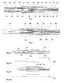
- Fig. 1 is a side view of a first embodiment of the present invention in cross-section
- Fig. 2 is a side view of the embodiment of Fig. 1 in a cross-section taken 90° in relation to Fig. 1 ,
- Figs. 3-5 show the embodiment according to Fig. 1 in different operational positions
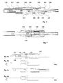
- Fig. 6 is a side view of another embodiment of the present invention in cross-section
- Fig. 7 is a side view of the embodiment of Fig. 6 in a cross-section taken 90° in relation to Fig. 6 ,
- Figs. 8-9 show the embodiment according to Fig. 6 in different operational positions
- Fig. 10 is a detailed view of the embodiment according to Fig. 6 .
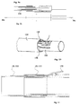
- Fig. 11 is a detailed view of a release means comprised in the present invention.
- Fig. 12 a-b are detailed views of another release means comprised in the present invention.
- Fig. 13 a-b are detailed views of a further release means comprised in the present invention.
- Figures 1 and 2 show one embodiment of the present invention. It comprises a generally tubular elongated outer housing 10 having a front end, to the left in the figures, to be placed at the injection site of a patient.
- the injector When the injector is delivered to a user it is arranged with a protective cap 12 at its front end.
- a needle sheath is attached, which needle sheath 14 surrounds and protects an injection needle 16.
- a tubular needle shield 18 is arranged surrounding the needle.
- a pair of tongues 20 is arranged having inwardly protruding ledges 21.
- the needle shield further extends up along the inner surface of the housing.
- a needle shield spring 22 is arranged between the distal end surface of the needle shield and a ledge 24 on the inner surface of the housing.
- a tubular member 26 is arranged, hereafter named needle shield link. It is connected to the needle shield via inwardly extending tongues 28 on the needle shield that fit into recesses 30 in the needle shield link.
- a medicament container holder 32 is slidably arranged, as will be described in more detail below.
- a medicament container 34 e.g. a cartridge, a syringe or the like; is attached, which then also is slidable.
- the container holder is held from moving forward by the ledges 21 on the needle shield.
- a plunger rod 36 is arranged between a stopper 38 of the container and a distal end wall 40 of the housing.
- a compression spring 42 is arranged between a front end wall of the plunger rod and the distal end wall of the housing. At a certain distance from the front end of the plunger rod, it is arranged with oppositely placed, outwardly protruding ledges 44.
- the needle shield link is further arranged with two elongated, oppositely arranged, slots 54, Fig. 2 , in which arms 56 are attached.
- the arms have an inwardly inclined first direction and an outwardly inclined second direction, where the transition 58 between the sections is in contact with the plunger rod.
- the free ends 60 of the arms are in the slots.
- the upper, rear end of the plunger rod is arranged with a thicker section, Fig. 2 .
- the device is intended to function as follows. When the device is delivered, it is arranged with the protective cap 12 mounted on the front end of the device. When a user is to administer a dose of medicament, the cap is removed. An inner sleeve 62 of the cap is arranged with a hook 64 that grips into the resilient needle sheath 14, so that when the cap is removed so is also the needle sheath. The syringe housing and the syringe are prevented from being pulled out when the cap is removed due to the inwardly directed ledges 21 holding the syringe holder.
- Fig. 2 When the cap is removed the delivery device is ready for use, Fig. 2 .
- the needle shield link 26 has been pushed a certain distance, the ledges 46 holding the plunger rod 36 will pass the narrower tubular part 52 of the needle shield link and move into two elongated slots 66 in the needle shield link. This allows the arms to flex outwardly thereby releasing the plunger rod.
- the plunger rod now moves forward due to the force from the compression spring 42, pressing on the stopper 38 of the container 34. Due to the incompressibility of the medicament in liquid form, the container 34 and container holder 32 are moved forward. This is enabled in that the inwardly directed ledges 21 of the needle shield, that previously held the container holder in place, are now free to flex outwardly. Thus a penetration into the tissue of the patient is performed, Figs. 3 . The movement of the container holder, and thus the penetration, is stopped when an annular ledge 68 of the container holder comes in contact with inwardly directed ledges 70 of a component 72, called syringe housing, attached to the housing.
- a component 72 called syringe housing
- the force of the compression spring on the plunger rod causes the latter to move the stopper 38 forward, thereby injecting medicament through the needle 16 and into the tissue of the patient.
- the injection is stopped when the stopper abuts the front end wall of the container, Figs. 4 .
- FIGS. 6-10 show another embodiment of the present invention.
- the injecting device comprises a generally tubular main body 110.
- a needle shield 112 is arranged slidably inside the main housing.
- a protective cap 114 is arranged in the same manner as the previous embodiment.
- a container 116 attached to a container holder 118 are held in place by inwardly extending ledges 120 on arms of the needle shield, which arms are held from flexing outwards by the cap.
- a generally tubular member 122 hereafter named rotator, is rotationally and slidably arranged at the rear part of the needle shield. It is arranged with a number of ridges and knobs 123 on its outer surface which are to cooperate with guide members arranged on the inner surface of the needle shield, the function of which will be explained below.
- the upper end surface of the rotator 122 is in contact with a wall surface 124 of the housing, preventing longitudinal movement but allowing rotational movement between them.
- a plunger rod 126 is slidably arranged and movable with the help of a compression spring (not shown).
- the upper part of the plunger rod is arranged with a number of outwardly extending stop members 128, Fig. 7 , arranged to cooperate with inwardly extending stop members 130 on the inner surface of the rotator, as will be explained below.
- the front end of the plunger rod is in contact with a stopper 132 arranged inside the container.
- the lower end surface of the rotator is in contact with an end wall of a component, syringe housing 134, attached to the housing.
- a needle shield spring (not shown) is arranged to press on the needle shield between a ledge on the housing and on the upper end surface of the needle shield.
- the device is intended to function as follows. When the device is assembled and delivered to the user the protective cap 114 is covering the front end with the needle shield 114. The plunger rod 126 is in its rearmost position and the injection spring is tensioned. The plunger rod is held in this position by a set of oppositely arranged outwardly extending knobs 128, on the plunger rod abutting a set of ledges 130 arranged on the inner surface of the rotator.
- the protective cap When the patient is to use the device the protective cap is removed and in the same manner as with the previous embodiment, the needle sheath is also removed, Fig. 7 .
- the device is now ready for injection.
- the needle shield 112 is pressed against the injection site and the needle penetrates the skin.
- the guide knobs 123 of the needle shield run along longitudinally extending ridges 136, until they come in contact with inclined ledges 138, Fig. 6 .
- the contact between these causes the rotator to turn during further movement of the needle shield.
- the rotator is thus turned until the outwardly extending knobs 128 of the plunger rod 126 slip off the ledges 130 arranged on the upper part of the rotator, thereby starting the penetration.
- the plunger rod moves downward due to the force of the injection spring and the knobs 123 run in longitudinal grooves on the inner surface of the rotator.
- the movement of the plunger rod causes the container 116 with the container holder 118 to move forward due to the incompressibility of the medicament inside the container, causing a penetration, Fig. 8 .
- the movement of the container is stopped when an annular ledge 140 on the outer surface of the container holder abuts inwardly extending ledges 142 of the container housing 134.
- the further movement of the plunger moves the stopper, whereby medicament is injected through the needle, until the stopper abuts the front end wall of the container.
- the user When the injection is finished, the user removes the device from the injection site, whereby the needle shield 112 moves into an extended position due to the force of the needle shield spring.
- the guide knobs 123 of the needle shield now move along the other side of the ridges 136 and at a certain position along this path, when the needle shield is in its most extended position covering the needle, the guide knobs fit into recesses in the rotator, thereby locking the needle shield in the extended position, preventing the needle shield to be pushed in again. The risk of unintentional needle sticks is thus eliminated.
- the injector can be provided with release means.
- the release means could comprise locking members that when inactivated locks the needle shield 18; 112 in the initial retracted position.
- the release means could comprise push buttons 148 arranged at the front of the injector. They are preferably placed there in order that the patient uses an ergonomic grip e.g. pen like grip, to hold the injector. In this aspect, there could be two buttons that need to be operated, one on each side of the injector.
- the release means could comprise a sleeve 150, Fig. 12 , arranged at the front end of the injector, which is slidable in the elongated direction of the injector for releasing the needle shield.
- the sleeve is preferably moved in the forward direction when the patient presses the injector against the injection site. This causes a flexible locking member 152 protruding through the housing to move from a position where it blocks the needle shield from moving into the housing, Fig. 12a , to a position where the locking member has been moved into the wall of the housing, freeing the needle shield, Fig. 12b .
- Other release members are feasible, such as sliding buttons.
- FIG. 13 A further example of release means is shown in Fig. 13 .
- the front end of a housing 170 is made somewhat elliptic in cross-section with a shorter axis 152 that is generally equal to the diameter of the needle shield 154, where the needle shield is arranged with slots 156 in which the end surface of the housing at the shorter axis fit, whereby the needle shield is locked from movement.
- the longer axis 158 of the ellipse is larger than the diameter of the needle shield, creating a space 160 between the housing and the needle shield on both sides.
- the housing at the shorter axis will flex radially outwards, as indicated by arrows 164, whereby the housing moves out of the slots of the needle shield, thereby freeing it for movement, as described above.
Abstract
Description
- The present invention relates to an auto-injector comprising needle shield activation of the penetration and subsequent injection.
- For many patients using injecting devices for self-administration of medicament, there is a discomfort to handle the device, especially regarding the penetration. For many users there is a mental resistance against self-penetration. Other users also have a general fear of needles which enhances the discomfort and negative feeling of self-administration.
- It is further desirable for many patients that the number of actions that the patient needs to perform in order to receive a dose of medicament is held as low as possible, on the one hand regarding handling of the device and on the other hand the functionality of the device.
- One such device is disclosed in patent
EP 1349590 B (SHL MEDICAL AB ) 08.10.2003 describing an injector having a number of features that facilitate the handling of the injector. The penetration and injection is performed automatically by pressing a button on the upper end of the injector. When the injection is performed the injector is withdrawn whereby a needle shield extracts around the needle in a locked way. As an additional safety aspect, the activation cannot be performed unless the injector is pressed against an injection site, i.e. a two-step operation to activate the injector is required. - Another type of injecting device is shown in
US 5478316 ( BECTON DICKINSON CO ) 26.12.1995 disclosing a high degree of automatic functions. When a sleeve at the front injection end of the injector, being the needle shield, is pressed against an injection site, the sleeve is moved a certain distance into the injector. The movement enables a push button arranged about midway on the side of the injector housing to be pressed by the user. This in turn releases a constant spring means acting on a driver and rod unit in contact with a syringe assembly so that a penetration is performed. When a certain penetration depth is reached, the driver is disconnected from the rod and the rod is urged further by the spring, causing an injection of medicament into the injection site. After the injection is completed the device is withdrawn from the injection site, whereby the sleeve moves forward, covering the needle. - Another aspect of injectors is the human aspect of handling the injector regarding how it is held during operation. A general aim is to have the patient holding the injector in an ergonomic way that may permits the penetration and injection in different locations on the body, such as around the waist and also on the backside of the waist and/or in the buttocks of the patient. The patient does not see the injector at those locations and need to be able to hold the injector without having to change grip. One suitable ergonomic grip for many locations is e.g. the pen grip, whereby the user holds the injector in the front, injection area. This could be difficult when the injector has push buttons on the distal end of the injector or slide buttons on the side of the injector.
- The aim of the present invention is to provide an injector having a high degree of functionality, that is easy to use and reliable, and which preferably provides a level of handling freedom for each patient.
- This aim is obtained by the features of the independent patent claim. Preferable embodiments of the invention are subject of the dependent patent claims.
- According to a main aspect of the invention, it is characterised by a device for delivering a dose of medicament, comprising a generally elongated housing, a container containing medicament to be injected through a needle, force means acting on said container and capable of, upon activation, move said container and said needle for penetration and subsequently expelling medicament through said needle, activating means arranged to activate said force means, wherein said activating means comprises a needle shield arranged slidable in relation to said housing, which upon movement releases said force means, release means arranged in the front, injecting, area of the device, which, when in a non-activated state prevents said needle shield from sliding, thereby preventing activation, and when activated, enables sliding of said needle shield and thereby activation of said device, and that said release means is arranged such on the device that it promotes an ergonomic grip of the device for its activation.
- The release means may comprise at least one button to be activated in order to enable movement of said needle shield, and two or possibly more buttons arranged such that it guides a user to hold the device like a pen for activation. Said button(s) also increase(s) the degree of safety and ergonomics.
- Said button(s) could be push buttons, sliding buttons or arranged as a sleeve slidable in relation to said housing.
- The sleeve is preferably slidable in a forward direction from a non-activated state to an activated state, thereby enabling sliding of said needle shield.
- According to a further aspect of the invention, said force means comprises a plunger rod and a compression spring acting on said plunger rod, which acts on a stopper arranged in said container.
- According to yet an aspect of the invention, said activating means comprises flexible locking means arranged to hold said plunger rod with the compression spring in a tensioned state, which flexible locking means are released when said needle shield is moved a certain distance, releasing said plunger rod.
- According to an alternative aspect of the invention, said activating means comprises stop ledges co-acting with ledges on said plunger rod to hold said plunger rod with the compression spring in a tensioned state, which stop ledges are arranged on a rotatable component and means arranged on said needle shield capable of rotating said rotatable component when said needle shield is moved a certain distance, rotating said stop ledges out of contact with said ledges on said plunger rod, releasing said plunger rod.
- The needle shield may be arranged with protrusions co-acting with inclined ridges on said rotatable component causing the rotatable component to rotate when said needle shield is moved.
- According to a further aspect of the invention, it further comprises means for pushing said needle shield to an extended position, and in some cases beyond the initial position, covering said needle when said device is withdrawn from an injection site, and means for locking said needle shield in the extended position.
- The device according to the present invention presents a number of advantages. There is a high degree of functionality and automation since the activation of the injector, comprising both penetration and injection is enabled by the needle shield when pushing the injector against the injection site. This causes the needle shield to slide a distance, whereby the injector is activated.
- The discomfort of having to penetrate manually by the user is thus removed. The only manual action that the patient needs to perform is to withdraw the injector from the site. During withdrawal, the needle shield is pushed out and covers the needle, and also locks in the extended state, thereby preventing unintentional needle sticks.
- A reliable and functional injector is provided because one compression spring in cooperation with a plunger rod, performs both the penetration and subsequent injection, thus also reducing the number of components of the injector. The plunger rod is held with the compression spring in a tensioned state when delivered to the user, whereby no additional operations, apart from removing a protection cap, need to be performed in order to have the injector ready for injection.
- In order to elevate the safety aspect of the injector and also provide a freedom of handling and holding of the injector during its use, release means are arranged at the front, injection, end of the device. When the release means are not activated, they prevent the needle shield from being moved and thus the injector can not be activated. When the release means are activated, e.g. by pushing or sliding buttons by the fingers of the user, the needle shield can slide into the housing and activate the device. Because the release means are arranged at the front end of the injector, this promotes the user to hold the injector as a pen, which is desirable for many applications and drugs.
- These and other aspects of and advantages with the present invention will become apparent from the following detailed description and from the accompanying drawings.
- In the following detailed description of the invention, reference will be made to the accompanying drawings, of which
-
Fig. 1 is a side view of a first embodiment of the present invention in cross-section, -
Fig. 2 is a side view of the embodiment ofFig. 1 in a cross-section taken 90° in relation toFig. 1 , -
Figs. 3-5 show the embodiment according toFig. 1 in different operational positions, -
Fig. 6 is a side view of another embodiment of the present invention in cross-section, -
Fig. 7 is a side view of the embodiment ofFig. 6 in a cross-section taken 90° in relation toFig. 6 , -
Figs. 8-9 show the embodiment according toFig. 6 in different operational positions, -
Fig. 10 is a detailed view of the embodiment according toFig. 6 , -
Fig. 11 is a detailed view of a release means comprised in the present invention, -
Fig. 12 a-b are detailed views of another release means comprised in the present invention, and -
Fig. 13 a-b are detailed views of a further release means comprised in the present invention. -
Figures 1 and 2 show one embodiment of the present invention. It comprises a generally tubular elongatedouter housing 10 having a front end, to the left in the figures, to be placed at the injection site of a patient. When the injector is delivered to a user it is arranged with aprotective cap 12 at its front end. To the protective cap a needle sheath is attached, which needlesheath 14 surrounds and protects aninjection needle 16. Inside the front cap atubular needle shield 18 is arranged surrounding the needle. At a mid part of the needle shield, a pair oftongues 20 is arranged having inwardly protrudingledges 21. The needle shield further extends up along the inner surface of the housing. Aneedle shield spring 22 is arranged between the distal end surface of the needle shield and aledge 24 on the inner surface of the housing. Inside the needle shield atubular member 26 is arranged, hereafter named needle shield link. It is connected to the needle shield via inwardly extendingtongues 28 on the needle shield that fit intorecesses 30 in the needle shield link. - Inside the needle shield link a
medicament container holder 32 is slidably arranged, as will be described in more detail below. Inside the container holder amedicament container 34 e.g. a cartridge, a syringe or the like; is attached, which then also is slidable. The container holder is held from moving forward by theledges 21 on the needle shield. Aplunger rod 36 is arranged between astopper 38 of the container and adistal end wall 40 of the housing. Inside the plunger rod acompression spring 42 is arranged between a front end wall of the plunger rod and the distal end wall of the housing. At a certain distance from the front end of the plunger rod, it is arranged with oppositely placed, outwardly protrudingledges 44. In the start position, these ledges abut inwardly protrudingledges 46 arranged onarms 48 on an innertubular structure 50 of the housing. The arms are held in this position by the rear, tubular part of the needle shield link. The needle shield link is further arranged with two elongated, oppositely arranged,slots 54,Fig. 2 , in whicharms 56 are attached. The arms have an inwardly inclined first direction and an outwardly inclined second direction, where thetransition 58 between the sections is in contact with the plunger rod. The free ends 60 of the arms are in the slots. The upper, rear end of the plunger rod is arranged with a thicker section,Fig. 2 . - The device is intended to function as follows. When the device is delivered, it is arranged with the
protective cap 12 mounted on the front end of the device. When a user is to administer a dose of medicament, the cap is removed. Aninner sleeve 62 of the cap is arranged with ahook 64 that grips into theresilient needle sheath 14, so that when the cap is removed so is also the needle sheath. The syringe housing and the syringe are prevented from being pulled out when the cap is removed due to the inwardly directedledges 21 holding the syringe holder. - When the cap is removed the delivery device is ready for use,
Fig. 2 . The user presses the front end of theneedle shield 18 against the injection site whereby the needle shield is pushed into the housing. Because the needle shield is connected to the needle shield link, also the latter is pushed rearwards. When theneedle shield link 26 has been pushed a certain distance, theledges 46 holding theplunger rod 36 will pass the narrowertubular part 52 of the needle shield link and move into twoelongated slots 66 in the needle shield link. This allows the arms to flex outwardly thereby releasing the plunger rod. - The plunger rod now moves forward due to the force from the
compression spring 42, pressing on thestopper 38 of thecontainer 34. Due to the incompressibility of the medicament in liquid form, thecontainer 34 andcontainer holder 32 are moved forward. This is enabled in that the inwardly directedledges 21 of the needle shield, that previously held the container holder in place, are now free to flex outwardly. Thus a penetration into the tissue of the patient is performed,Figs. 3 . The movement of the container holder, and thus the penetration, is stopped when anannular ledge 68 of the container holder comes in contact with inwardly directedledges 70 of acomponent 72, called syringe housing, attached to the housing. - The force of the compression spring on the plunger rod causes the latter to move the
stopper 38 forward, thereby injecting medicament through theneedle 16 and into the tissue of the patient. The injection is stopped when the stopper abuts the front end wall of the container,Figs. 4 . - The injection is now completed and the device can be withdrawn from the injection site. This enables the
needle shield 18 to move back out again with the help of theneedle shield spring 22. During the previous injection of medicament, the plunger rod moved forward, and during this movement the enlargedrear part 61 of the plunger rod came in contact with thetransition 58 of theinclined arms 56, urging thefree end 60 of the arms out of the sleeves and in contact with the inner surface of the housing. When the needle shield now has been moved out again the free ends of the arms will be pushed past acircumferential ledge 74 of the housing. This will lock the needle shield in the extracted position, which is extended further than the initial position, because the free ends of the arms will come in contact with the circumferential ledge and prevent any inwardly movement,Figs. 5 . By this any accidental needle sticks of the used needle are prevented. -
Figures 6-10 show another embodiment of the present invention. The injecting device comprises a generally tubularmain body 110. Aneedle shield 112 is arranged slidably inside the main housing. Aprotective cap 114 is arranged in the same manner as the previous embodiment. Also here acontainer 116 attached to acontainer holder 118 are held in place by inwardly extendingledges 120 on arms of the needle shield, which arms are held from flexing outwards by the cap. Inside the housing a generallytubular member 122, hereafter named rotator, is rotationally and slidably arranged at the rear part of the needle shield. It is arranged with a number of ridges andknobs 123 on its outer surface which are to cooperate with guide members arranged on the inner surface of the needle shield, the function of which will be explained below. - The upper end surface of the
rotator 122 is in contact with awall surface 124 of the housing, preventing longitudinal movement but allowing rotational movement between them. Inside the rotator, aplunger rod 126 is slidably arranged and movable with the help of a compression spring (not shown). The upper part of the plunger rod is arranged with a number of outwardly extendingstop members 128,Fig. 7 , arranged to cooperate with inwardly extendingstop members 130 on the inner surface of the rotator, as will be explained below. The front end of the plunger rod is in contact with astopper 132 arranged inside the container. The lower end surface of the rotator is in contact with an end wall of a component,syringe housing 134, attached to the housing. A needle shield spring (not shown) is arranged to press on the needle shield between a ledge on the housing and on the upper end surface of the needle shield. - The device is intended to function as follows. When the device is assembled and delivered to the user the
protective cap 114 is covering the front end with theneedle shield 114. Theplunger rod 126 is in its rearmost position and the injection spring is tensioned. The plunger rod is held in this position by a set of oppositely arranged outwardly extendingknobs 128, on the plunger rod abutting a set ofledges 130 arranged on the inner surface of the rotator. - When the patient is to use the device the protective cap is removed and in the same manner as with the previous embodiment, the needle sheath is also removed,
Fig. 7 . The device is now ready for injection. Theneedle shield 112 is pressed against the injection site and the needle penetrates the skin. During the inward movement of the needle shield the guide knobs 123 of the needle shield run along longitudinally extendingridges 136, until they come in contact withinclined ledges 138,Fig. 6 . The contact between these causes the rotator to turn during further movement of the needle shield. The rotator is thus turned until the outwardly extendingknobs 128 of theplunger rod 126 slip off theledges 130 arranged on the upper part of the rotator, thereby starting the penetration. The plunger rod moves downward due to the force of the injection spring and theknobs 123 run in longitudinal grooves on the inner surface of the rotator. The movement of the plunger rod causes thecontainer 116 with thecontainer holder 118 to move forward due to the incompressibility of the medicament inside the container, causing a penetration,Fig. 8 . The movement of the container is stopped when anannular ledge 140 on the outer surface of the container holder abuts inwardly extendingledges 142 of thecontainer housing 134. The further movement of the plunger moves the stopper, whereby medicament is injected through the needle, until the stopper abuts the front end wall of the container. - When the injection is finished, the user removes the device from the injection site, whereby the
needle shield 112 moves into an extended position due to the force of the needle shield spring. The guide knobs 123 of the needle shield now move along the other side of theridges 136 and at a certain position along this path, when the needle shield is in its most extended position covering the needle, the guide knobs fit into recesses in the rotator, thereby locking the needle shield in the extended position, preventing the needle shield to be pushed in again. The risk of unintentional needle sticks is thus eliminated. - In order to further enhance the safety of the device and to also ensure that the patient holds the injector in a proper way, the injector can be provided with release means. The release means could comprise locking members that when inactivated locks the
needle shield 18; 112 in the initial retracted position. According to one embodiment,Fig. 11 , the release means could comprise pushbuttons 148 arranged at the front of the injector. They are preferably placed there in order that the patient uses an ergonomic grip e.g. pen like grip, to hold the injector. In this aspect, there could be two buttons that need to be operated, one on each side of the injector. - According to another embodiment, the release means could comprise a
sleeve 150,Fig. 12 , arranged at the front end of the injector, which is slidable in the elongated direction of the injector for releasing the needle shield. For releasing the needle shield, the sleeve is preferably moved in the forward direction when the patient presses the injector against the injection site. This causes aflexible locking member 152 protruding through the housing to move from a position where it blocks the needle shield from moving into the housing,Fig. 12a , to a position where the locking member has been moved into the wall of the housing, freeing the needle shield,Fig. 12b . Apart from push buttons and sleeves, also other release members are feasible, such as sliding buttons. - A further example of release means is shown in
Fig. 13 . In this case the front end of ahousing 170 is made somewhat elliptic in cross-section with ashorter axis 152 that is generally equal to the diameter of theneedle shield 154, where the needle shield is arranged withslots 156 in which the end surface of the housing at the shorter axis fit, whereby the needle shield is locked from movement. Thelonger axis 158 of the ellipse is larger than the diameter of the needle shield, creating aspace 160 between the housing and the needle shield on both sides. - When a user presses in the area of the longer axis in a radial direction, as indicated with
arrows 162, which area preferably is marked in some way, like different colour for visual detection or grooves, indentations and the like for tactile detection, the housing at the shorter axis will flex radially outwards, as indicated byarrows 164, whereby the housing moves out of the slots of the needle shield, thereby freeing it for movement, as described above. - Even though the embodiments described above are intended to handle single chamber single dose containers, it is to be understood that the invention could be modified to handle other types of containers such as dual chamber containers that need mixing and priming before injection, and/or dose size setting means. Instead of one single spring performing both penetration and injection, several independent acting springs may be utilized for penetration and subsequent injection.
- It is thus to be understood that the embodiments described above and shown in the drawings are to be regarded only as non-limiting examples of the present invention and that it may be modified within the scope of the patent claims.
Claims (12)
- Device for delivering a dose of medicament, comprising a generally elongated housing (10; 110), a container (34; 116) containing medicament to be injected through a needle (16), force means acting on said container and capable of, upon activation, move said container and said needle for penetration and subsequently expelling medicament through said needle, activating means arranged to activate said force means (36, 42; 126), characterised in that said activating means (26, 50; 122) comprises a needle shield (18; 112; 154) arranged slidable in relation to said housing, which upon movement releases said force means, and release means (148; 150; 170) arranged in the front, injecting, area of the device, which, when in a non-activated state prevents said needle shield from sliding, thereby preventing activation, and when activated, enables sliding of said needle shield and thereby activation of said device, and that said release means is arranged such on the device that it promotes an ergonomic grip of the device for its activation.
- Device according to claim 1, characterised in that said release means comprises at least one button (148) to be activated in order to enable movement of said needle shield (18; 112).
- Device according to claim 2, characterised in that said release means comprises two buttons arranged such that it guides a user to hold the device like a pen for activation.
- Device according to any of claims 2 or 3, characterised in that said button(s) is/are push buttons or sliding buttons.
- Device according to claim 1, characterised in that said release means is arranged as a sleeve (150) slidable in relation to said housing (10; 110).
- Device according to claim 5, characterised in that said sleeve is slidable in a forward direction from a non-activated state to an activated state, thereby enabling sliding of said needle shield (18; 112).
- Device according to claim 1, characterised in that said release means comprises a deformable front end of the housing (170), which, when pressed radially by a user, expands radially from an interlocking position with the needle shield (154) to a release position.
- Device according to claim 1, characterised in that said force means comprises a plunger rod (36; 126) and a compression spring (42) acting on said plunger rod, which acts on a stopper arranged in said container.
- Device according to claim 8, characterised in that said activating means comprises flexible locking means (28, 46, 56) arranged to hold said plunger rod (36) with the compression spring (42) in a tensioned state, which flexible locking means are released when said needle shield (18; 154)is moved a certain distance, releasing said plunger rod.
- Device according to claim 8, characterised in that said activating means comprises stop ledges (130) co-acting with ledges (128) on said plunger rod (136) to hold said plunger rod with the compression spring in a tensioned state, which stop ledges are arranged on a rotatable component (122) and means arranged on said needle shield capable of rotating said rotatable component when said needle shield (110; 154) is moved a certain distance, rotating said stop ledges out of contact with said ledges on said plunger rod, releasing said plunger rod.
- Device according to claim 10, characterised in that said needle shield is arranged with protrusions co-acting with inclined ridges (138) on said rotatable component causing the rotatable component to rotate when said needle shield is moved.
- Device according to any of the preceding claims, characterised in that it further comprises means (22) for pushing said needle shield (18; 110; 154) to an extended position covering said needle when said device is withdrawn from an injection site, and means (74; 123) for locking said needle shield in the extended position.
Priority Applications (6)
| Application Number | Priority Date | Filing Date | Title |
|---|---|---|---|
| ES06125980T ES2365931T3 (en) | 2006-12-13 | 2006-12-13 | AUTOMATIC INJECTOR |
| DK06125980.0T DK1932558T3 (en) | 2006-12-13 | 2006-12-13 | autoinjector |
| AT06125980T ATE514443T1 (en) | 2006-12-13 | 2006-12-13 | AUTOINJECTOR |
| EP06125980A EP1932558B1 (en) | 2006-12-13 | 2006-12-13 | Auto-Injector |
| US11/949,947 US8062255B2 (en) | 2006-12-13 | 2007-12-04 | Auto-injector |
| JP2007318763A JP4864863B2 (en) | 2006-12-13 | 2007-12-10 | Automatic syringe |
Applications Claiming Priority (1)
| Application Number | Priority Date | Filing Date | Title |
|---|---|---|---|
| EP06125980A EP1932558B1 (en) | 2006-12-13 | 2006-12-13 | Auto-Injector |
Publications (2)
| Publication Number | Publication Date |
|---|---|
| EP1932558A1 true EP1932558A1 (en) | 2008-06-18 |
| EP1932558B1 EP1932558B1 (en) | 2011-06-29 |
Family
ID=37983893
Family Applications (1)
| Application Number | Title | Priority Date | Filing Date |
|---|---|---|---|
| EP06125980A Not-in-force EP1932558B1 (en) | 2006-12-13 | 2006-12-13 | Auto-Injector |
Country Status (6)
| Country | Link |
|---|---|
| US (1) | US8062255B2 (en) |
| EP (1) | EP1932558B1 (en) |
| JP (1) | JP4864863B2 (en) |
| AT (1) | ATE514443T1 (en) |
| DK (1) | DK1932558T3 (en) |
| ES (1) | ES2365931T3 (en) |
Cited By (51)
| Publication number | Priority date | Publication date | Assignee | Title |
|---|---|---|---|---|
| US20090234297A1 (en) * | 2005-04-06 | 2009-09-17 | Douglas Ivan Jennings | Injection device |
| EP2175915A1 (en) | 2007-08-08 | 2010-04-21 | Cilag GmbH International | Injection device with locking mechanism for syringe carrier |
| WO2010100246A1 (en) | 2009-03-06 | 2010-09-10 | Sanofi-Aventis Deutschland Gmbh | Syringe, auto-injector device and set of auto-injector devices and syringes |
| WO2010127449A1 (en) * | 2009-05-07 | 2010-11-11 | Medical Injection Devices Inc. | Medicament dispensing device |
| WO2011112136A1 (en) | 2010-03-09 | 2011-09-15 | Shl Group Ab | Medicament delivery device |
| WO2012045350A1 (en) * | 2010-10-06 | 2012-04-12 | Tecpharma Licensing Ag | Locking and retaining mechanism for the needle guard sleeve of an injection device |
| EP2489386A1 (en) * | 2011-02-18 | 2012-08-22 | Sanofi-Aventis Deutschland GmbH | Auto-injector |
| GB2451662B (en) * | 2007-08-08 | 2012-09-19 | Cilag Gmbh Int | Injection device |
| US8277414B2 (en) | 2004-05-28 | 2012-10-02 | Cilag Gmbh International | Injection device |
| US8313465B2 (en) | 2004-05-28 | 2012-11-20 | Cilag Gmbh International | Injection device |
| US8313463B2 (en) | 2004-05-28 | 2012-11-20 | Cilag Gmbh International | Injection device |
| US8313464B2 (en) | 2004-05-28 | 2012-11-20 | Cilag Gmbh International | Injection device |
| US8317751B2 (en) | 2005-04-06 | 2012-11-27 | Cilag Gmbh International | Injection device |
| US8343110B2 (en) | 2004-05-28 | 2013-01-01 | Cilag Gmbh International | Injection device |
| KR20130012965A (en) * | 2010-03-31 | 2013-02-05 | 에스에이치엘 그룹 에이비 | Medicament delivery device |
| US8366669B2 (en) | 2005-04-06 | 2013-02-05 | Cilag Gmbh International | Injection device |
| WO2013016832A1 (en) | 2011-08-04 | 2013-02-07 | Tecpharma Licensing Ag | Safety arrangement for injection devices |
| WO2013048310A1 (en) * | 2011-09-27 | 2013-04-04 | Shl Group Ab | Medical delivery device with an initial locked state, intermediate priming state and a medicament delivery state |
| US8845594B2 (en) | 2008-06-19 | 2014-09-30 | Cilag Gmbh International | Auto-injector with filling means |
| US8939958B2 (en) | 2008-06-19 | 2015-01-27 | Cilag Gmbh International | Fluid transfer assembly for a syringe |
| US9072833B2 (en) | 2006-06-01 | 2015-07-07 | Cilag Gmbh International | Injection device |
| WO2015047758A3 (en) * | 2013-09-13 | 2015-07-23 | Unitract Syringe Pty Ltd | Automatic self-dispensing accurate dose drug delivery syringes |
| EP2750738A4 (en) * | 2011-08-31 | 2015-08-05 | Shl Group Ab | Injection device |
| EP2695630A4 (en) * | 2011-04-07 | 2015-12-30 | Terumo Corp | Liquid infusion instrument |
| US9265892B2 (en) | 2009-05-07 | 2016-02-23 | Eric Segal | Medicament dispensing device |
| RU2593984C1 (en) * | 2010-03-31 | 2016-08-10 | Схл Груп Аб | Drug administration device comprising signal feedback |
| US9604003B2 (en) | 2011-02-18 | 2017-03-28 | Sanofi-Aventis Deutschland Gmbh | Auto-injector |
| US9636459B2 (en) | 2011-02-18 | 2017-05-02 | Sanofi-Aventis Deutschland Gmbh | Auto-injector |
| US9649441B2 (en) | 2005-04-06 | 2017-05-16 | Cilag Gmbh International | Injection device (bayonet cap removal) |
| EP2533835B1 (en) * | 2010-02-11 | 2017-05-17 | tip-top.com Ltd | Medical needle cover arrangement |
| US9656021B2 (en) | 2011-02-18 | 2017-05-23 | Sanofi-Aventis Deutschland Gmbh | Auto-injector |
| US9682194B2 (en) | 2008-06-19 | 2017-06-20 | Cilag Gmbh International | Re-useable auto-injector with filling means |
| US9757520B2 (en) | 2006-06-01 | 2017-09-12 | Cilag Gmbh International | Injection device |
| US9789255B2 (en) | 2011-02-18 | 2017-10-17 | Sanofi-Aventis Deutschland Gmbh | Auto-injector |
| EP2665503A4 (en) * | 2011-01-11 | 2017-11-29 | SHL Group AB | Medicament delivery device |
| US9895493B2 (en) | 2004-05-28 | 2018-02-20 | Cilag Gmbh International | Injection device |
| EP2611478A4 (en) * | 2010-09-02 | 2018-02-21 | Becton, Dickinson and Company | Self-injection device having needle cover with activation preventer |
| US9925344B2 (en) | 2011-02-18 | 2018-03-27 | Sanofi-Aventis Deutschland Gmbh | Auto-injector |
| US9931471B2 (en) | 2010-06-28 | 2018-04-03 | Sanofi-Aventis Deutschland Gmbh | Auto-injector |
| US9950123B2 (en) | 2011-02-18 | 2018-04-24 | Sanofi-Aventis Deutschland Gmbh | Detent mechanism |
| WO2019086371A1 (en) * | 2017-10-30 | 2019-05-09 | Sanofi | Injector device |
| US10328211B2 (en) | 2011-12-08 | 2019-06-25 | Unl Holdings Llc | Automatic self-dispensing accurate dose drug delivery syringes |
| US10376641B2 (en) | 2008-08-11 | 2019-08-13 | Tecpharma Licensing Ag | Automatic injection device for administering a fixed dose |
| US10384016B2 (en) | 2011-02-18 | 2019-08-20 | Sanofi-Aventis Deutschland Gmbh | Auto-injector |
| US10518041B2 (en) | 2011-02-18 | 2019-12-31 | Sanofi-Aventis Deutschland Gmbh | Injection device |
| US10709840B2 (en) | 2007-06-29 | 2020-07-14 | Tecpharma Licensing Ag | Injection device with a spring for a needle protecting sleeve |
| WO2020210513A1 (en) * | 2019-04-09 | 2020-10-15 | Battelle Memorial Institute | Autoinjectors having advanced release and sound features |
| US10881799B2 (en) | 2013-03-22 | 2021-01-05 | Ypsomed Ag | Autoinjector with a signaling device |
| US10960143B2 (en) | 2003-12-18 | 2021-03-30 | Ypsomed Ag | Auto-injector with active agent container latching |
| US11752266B2 (en) | 2015-06-03 | 2023-09-12 | Sanofi-Aventis Deutschland Gmbh | Syringe support and autoinjector |
| US11964132B2 (en) | 2008-08-11 | 2024-04-23 | Ypsomed Ag | Automatic injection device for administering a fixed dose |
Families Citing this family (81)
| Publication number | Priority date | Publication date | Assignee | Title |
|---|---|---|---|---|
| GB2414775B (en) | 2004-05-28 | 2008-05-21 | Cilag Ag Int | Releasable coupling and injection device |
| GB2414402B (en) | 2004-05-28 | 2009-04-22 | Cilag Ag Int | Injection device |
| US7648483B2 (en) | 2004-11-22 | 2010-01-19 | Intelliject, Inc. | Devices, systems and methods for medicament delivery |
| US10737028B2 (en) | 2004-11-22 | 2020-08-11 | Kaleo, Inc. | Devices, systems and methods for medicament delivery |
| US11590286B2 (en) | 2004-11-22 | 2023-02-28 | Kaleo, Inc. | Devices, systems and methods for medicament delivery |
| JP4960252B2 (en) | 2004-11-22 | 2012-06-27 | インテリジェクト,インコーポレイテッド | Device, system and method for drug delivery |
| JP4948422B2 (en) | 2005-02-01 | 2012-06-06 | インテリジェクト,インコーポレイテッド | Drug delivery apparatus, system and method |
| PL1759729T3 (en) | 2005-08-30 | 2010-09-30 | Cilag Gmbh Int | Needle assembly for a prefilled syringe system |
| US20110098656A1 (en) | 2005-09-27 | 2011-04-28 | Burnell Rosie L | Auto-injection device with needle protecting cap having outer and inner sleeves |
| FR2899482A1 (en) * | 2006-04-11 | 2007-10-12 | Becton Dickinson France Soc Pa | Automatic medicament/product injection device for patient, has safety shield coupled to housing, and provided in active state at end of needle insertion step before which product/medicament injection step is not started |
| GB2438593B (en) | 2006-06-01 | 2011-03-30 | Cilag Gmbh Int | Injection device (cap removal feature) |
| EP2195052B1 (en) | 2007-10-02 | 2019-09-04 | Medimop Medical Projects Ltd. | External drug pump |
| US8021344B2 (en) * | 2008-07-28 | 2011-09-20 | Intelliject, Inc. | Medicament delivery device configured to produce an audible output |
| CN102112165B (en) * | 2008-06-11 | 2013-05-29 | Shl集团有限责任公司 | Medicament delivery device |
| GB2461086B (en) | 2008-06-19 | 2012-12-05 | Cilag Gmbh Int | Injection device |
| GB2461089B (en) | 2008-06-19 | 2012-09-19 | Cilag Gmbh Int | Injection device |
| US9901681B2 (en) * | 2008-09-18 | 2018-02-27 | Becton, Dickinson And Company | Medical injector with slidable sleeve activation |
| GB0907534D0 (en) | 2009-05-01 | 2009-06-10 | Owen Mumford Ltd | Injection devices |
| WO2010136078A1 (en) | 2009-05-29 | 2010-12-02 | Tecpharma Licensing Ag | Injection device, especially auto-injector, comprising an anti-pricking mechanism and/or overload protection for a product container. |
| TWI393578B (en) * | 2009-07-07 | 2013-04-21 | Shl Group Ab | Injection device |
| WO2011101379A1 (en) | 2010-02-18 | 2011-08-25 | Sanofi-Aventis Deutschland Gmbh | Auto-injector |
| JP2013523202A (en) | 2010-03-25 | 2013-06-17 | ニュー インジェクション システムズ リミテッド | Syringe |
| JP5512883B2 (en) * | 2010-05-07 | 2014-06-04 | エス・ホー・エル・グループ・アクチボラゲット | Drug delivery device |
| EP2399633A1 (en) * | 2010-06-28 | 2011-12-28 | Sanofi-Aventis Deutschland GmbH | Needle safety arrangement and method for operating it |
| EP2585138B1 (en) * | 2010-06-28 | 2016-04-20 | Sanofi-Aventis Deutschland GmbH | Auto-injector |
| BR112012033606A2 (en) * | 2010-07-02 | 2019-09-24 | Carebay Holding Ltd Company No 681498 | condom free follicle stimulating hormone solution delivery device |
| EP2468333A1 (en) | 2010-12-21 | 2012-06-27 | Sanofi-Aventis Deutschland GmbH | Auto-injector |
| USRE48593E1 (en) | 2010-12-21 | 2021-06-15 | Sanofi-Aventis Deutschland Gmbh | Auto-injector |
| EP2468335A1 (en) * | 2010-12-21 | 2012-06-27 | Sanofi-Aventis Deutschland GmbH | Auto-injector |
| EP2468330A1 (en) | 2010-12-21 | 2012-06-27 | Sanofi-Aventis Deutschland GmbH | Auto-injector |
| US9084849B2 (en) | 2011-01-26 | 2015-07-21 | Kaleo, Inc. | Medicament delivery devices for administration of a medicament within a prefilled syringe |
| ITFI20110193A1 (en) * | 2011-09-08 | 2013-03-09 | Menarini Int Operations Lu Sa | DEVICE FOR AUTOMATIC INJECTION OF TWO DRUG DOSES |
| ITFI20110194A1 (en) * | 2011-09-08 | 2013-03-09 | Menarini Int Operations Lu Sa | MEDICINE DOSES SELF-INJECTION DEVICE |
| WO2014080020A1 (en) | 2012-11-23 | 2014-05-30 | New Injection Systems Ltd | Auto-injector assembly |
| US8652100B1 (en) | 2013-03-08 | 2014-02-18 | Teva Pharmaceutical Industries, Ltd. | Re-useable injector device for syringe |
| US8591463B1 (en) | 2013-03-08 | 2013-11-26 | Teva Pharmaceutical Industries Ltd. | Re-useable injector device for syringe |
| EP3607821B1 (en) | 2013-03-15 | 2022-08-03 | EyePoint Pharmaceuticals, Inc. | Compositions, formulations and methods for treating ocular diseases |
| US20150050277A1 (en) | 2013-03-15 | 2015-02-19 | Aerpio Therapeutics Inc. | Compositions and methods for treating ocular diseases |
| GB2515039B (en) | 2013-06-11 | 2015-05-27 | Cilag Gmbh Int | Injection Device |
| GB2517896B (en) | 2013-06-11 | 2015-07-08 | Cilag Gmbh Int | Injection device |
| GB2515032A (en) | 2013-06-11 | 2014-12-17 | Cilag Gmbh Int | Guide for an injection device |
| GB2515038A (en) | 2013-06-11 | 2014-12-17 | Cilag Gmbh Int | Injection device |
| EP2823841A1 (en) | 2013-07-09 | 2015-01-14 | Sanofi-Aventis Deutschland GmbH | Autoinjector |
| WO2015018578A1 (en) * | 2013-08-08 | 2015-02-12 | Carebay Europe Ltd | Power unit |
| USD745664S1 (en) | 2013-11-25 | 2015-12-15 | Teva Pharmaceutical Industries, Ltd. | Injector device for a syringe |
| EP2923714A1 (en) | 2014-03-28 | 2015-09-30 | Sanofi-Aventis Deutschland GmbH | Autoinjector triggered by skin contact |
| BR112017011213A2 (en) | 2014-12-23 | 2018-02-14 | Automed Pty Ltd | delivery apparatus, system and associated methods |
| CN107438443B (en) | 2015-04-24 | 2020-09-01 | 艾斯曲尔医疗公司 | Driving mechanism |
| US20200384209A1 (en) * | 2015-04-24 | 2020-12-10 | Shl Medical Ag | Drive mechanism |
| JP6626131B2 (en) * | 2015-06-19 | 2019-12-25 | エス・ハー・エル・メディカル・アクチェンゲゼルシャフトShl Medical Ag | Drug delivery device |
| WO2017004345A1 (en) | 2015-06-30 | 2017-01-05 | Kaleo, Inc. | Auto-injectors for administration of a medicament within a prefilled syringe |
| US10576207B2 (en) | 2015-10-09 | 2020-03-03 | West Pharma. Services IL, Ltd. | Angled syringe patch injector |
| JP7017512B2 (en) | 2015-10-09 | 2022-02-08 | ウェスト ファーマ サービシーズ イスラエル リミテッド | Bending fluid path type accessories for filled fluid containers |
| US10529252B2 (en) * | 2015-11-19 | 2020-01-07 | Noble International, Inc. | Resettable shield-activated injection device trainer |
| WO2017089263A1 (en) | 2015-11-27 | 2017-06-01 | Sanofi-Aventis Deutschland Gmbh | A cap for an injection device |
| US11311674B2 (en) | 2016-01-21 | 2022-04-26 | West Pharma. Services IL, Ltd. | Medicament delivery device comprising a visual indicator |
| US10610638B2 (en) | 2016-01-21 | 2020-04-07 | West Pharma. Services IL, Ltd. | Force containment in an automatic injector |
| JP6542481B2 (en) | 2016-01-21 | 2019-07-10 | ウェスト ファーマ サービシーズ イスラエル リミテッド | system |
| WO2017161076A1 (en) | 2016-03-16 | 2017-09-21 | Medimop Medical Projects Ltd. | Staged telescopic screw assembly having different visual indicators |
| US11116911B2 (en) * | 2016-04-11 | 2021-09-14 | Biogen Ma, Inc. | Injector lockout prevention device |
| USD819198S1 (en) | 2016-04-28 | 2018-05-29 | Amgen Inc. | Autoinjector with removable cap |
| EP3458128B1 (en) * | 2016-05-18 | 2020-07-01 | SHL Medical AG | Administration mechanism for a medicament delivery device |
| DK3469573T3 (en) * | 2016-06-08 | 2024-03-04 | Shl Medical Ag | ADMINISTRATION MECHANISM FOR A DRUG DELIVERY TRAINING DEVICE |
| WO2018026387A1 (en) | 2016-08-01 | 2018-02-08 | Medimop Medical Projects Ltd. | Anti-rotation cartridge pin |
| EP3311863A1 (en) * | 2016-10-24 | 2018-04-25 | Carebay Europe Ltd. | Medicament delivery device having a cap assembly |
| US11617753B2 (en) | 2016-11-10 | 2023-04-04 | Oyagen, Inc. | Methods of treating and inhibiting Ebola virus infection |
| CA3046228A1 (en) | 2016-12-23 | 2018-06-28 | Kaleo, Inc. | Medicament delivery device and methods for delivering drugs to infants and children |
| WO2018222521A1 (en) | 2017-05-30 | 2018-12-06 | West Pharma. Services IL, Ltd. | Modular drive train for wearable injector |
| EP3492124A1 (en) * | 2017-12-01 | 2019-06-05 | Sanofi | Injector device |
| CA3145580A1 (en) | 2019-08-09 | 2021-02-18 | Kaleo, Inc. | Devices and methods for delivery of substances within a prefilled syringe |
| USD1010811S1 (en) | 2019-09-30 | 2024-01-09 | Amgen Inc. | Handheld drug delivery device |
| EP4058102A1 (en) * | 2019-11-11 | 2022-09-21 | SHL Medical AG | Medicament delivery device |
| US11738025B2 (en) | 2020-02-04 | 2023-08-29 | Oyagen, Inc. | Method for treating coronavirus infections |
| US11957542B2 (en) | 2020-04-30 | 2024-04-16 | Automed Patent Holdco, Llc | Sensing complete injection for animal injection device |
| USD973866S1 (en) | 2020-11-05 | 2022-12-27 | Amgen Inc. | Handheld drug delivery device |
| USD974547S1 (en) | 2020-11-05 | 2023-01-03 | Amgen Inc. | Handheld drug delivery device |
| USD962423S1 (en) | 2020-11-05 | 2022-08-30 | Amgen Inc. | Handheld drug delivery device |
| USD985118S1 (en) | 2021-03-10 | 2023-05-02 | Amgen Inc. | Handheld drug delivery device |
| USD985117S1 (en) | 2021-03-10 | 2023-05-02 | Amgen Inc. | Handheld drug delivery device |
| USD985116S1 (en) | 2021-03-10 | 2023-05-02 | Amgen Inc. | Handheld drug delivery device |
| USD985119S1 (en) | 2021-03-30 | 2023-05-02 | Amgen Inc. | Handheld drug delivery device |
Citations (6)
| Publication number | Priority date | Publication date | Assignee | Title |
|---|---|---|---|---|
| WO1999003529A2 (en) * | 1997-07-16 | 1999-01-28 | Owen Mumford Limited | Improvements relating to injection devices |
| US6203530B1 (en) * | 1997-01-28 | 2001-03-20 | Pos-T-Vac, Inc. | Auto-injection device |
| WO2002047746A1 (en) * | 2000-12-14 | 2002-06-20 | Shl Medical Ab | Auto-injector |
| US20050020979A1 (en) * | 2003-07-22 | 2005-01-27 | Safety Syringes, Inc. | Systems and methods for automatic medical injection with safeguard |
| WO2005009515A1 (en) * | 2003-07-31 | 2005-02-03 | Sid Technologies Llc | Injecting apparatus |
| US6986758B2 (en) * | 2001-06-20 | 2006-01-17 | Tecpharma Licensing Ag | Device for administering an injectable product in doses |
Family Cites Families (8)
| Publication number | Priority date | Publication date | Assignee | Title |
|---|---|---|---|---|
| FR2040830A5 (en) * | 1969-04-15 | 1971-01-22 | Ben Moura Pierre | |
| US4900311A (en) * | 1988-12-06 | 1990-02-13 | Lawrence Stern | Hypodermic syringe |
| US5478316A (en) | 1994-02-02 | 1995-12-26 | Becton, Dickinson And Company | Automatic self-injection device |
| DE19821933C1 (en) * | 1998-05-15 | 1999-11-11 | Disetronic Licensing Ag | Device for administering an injectable product |
| US6585685B2 (en) * | 2001-06-08 | 2003-07-01 | Bioject Inc. | Jet injector apparatus and method |
| DK1542744T3 (en) * | 2002-09-24 | 2009-09-28 | Shl Group Ab | injection device |
| GB0229345D0 (en) * | 2002-12-17 | 2003-01-22 | Safe T Ltd | Hollow needle applicators |
| DE102005017477A1 (en) * | 2005-02-18 | 2006-08-31 | Tecpharma Licensing Ag | Spring in or for an injection device |
-
2006
- 2006-12-13 EP EP06125980A patent/EP1932558B1/en not_active Not-in-force
- 2006-12-13 AT AT06125980T patent/ATE514443T1/en active
- 2006-12-13 ES ES06125980T patent/ES2365931T3/en active Active
- 2006-12-13 DK DK06125980.0T patent/DK1932558T3/en active
-
2007
- 2007-12-04 US US11/949,947 patent/US8062255B2/en not_active Expired - Fee Related
- 2007-12-10 JP JP2007318763A patent/JP4864863B2/en not_active Expired - Fee Related
Patent Citations (6)
| Publication number | Priority date | Publication date | Assignee | Title |
|---|---|---|---|---|
| US6203530B1 (en) * | 1997-01-28 | 2001-03-20 | Pos-T-Vac, Inc. | Auto-injection device |
| WO1999003529A2 (en) * | 1997-07-16 | 1999-01-28 | Owen Mumford Limited | Improvements relating to injection devices |
| WO2002047746A1 (en) * | 2000-12-14 | 2002-06-20 | Shl Medical Ab | Auto-injector |
| US6986758B2 (en) * | 2001-06-20 | 2006-01-17 | Tecpharma Licensing Ag | Device for administering an injectable product in doses |
| US20050020979A1 (en) * | 2003-07-22 | 2005-01-27 | Safety Syringes, Inc. | Systems and methods for automatic medical injection with safeguard |
| WO2005009515A1 (en) * | 2003-07-31 | 2005-02-03 | Sid Technologies Llc | Injecting apparatus |
Cited By (105)
| Publication number | Priority date | Publication date | Assignee | Title |
|---|---|---|---|---|
| US10973988B2 (en) | 2003-12-18 | 2021-04-13 | Ypsomed Ag | Auto-injector with active agent container latching |
| US11426529B2 (en) | 2003-12-18 | 2022-08-30 | Ypsomed Ag | Auto-injector with active agent container latching |
| US10960143B2 (en) | 2003-12-18 | 2021-03-30 | Ypsomed Ag | Auto-injector with active agent container latching |
| US8313463B2 (en) | 2004-05-28 | 2012-11-20 | Cilag Gmbh International | Injection device |
| US9895493B2 (en) | 2004-05-28 | 2018-02-20 | Cilag Gmbh International | Injection device |
| US8277414B2 (en) | 2004-05-28 | 2012-10-02 | Cilag Gmbh International | Injection device |
| US8313465B2 (en) | 2004-05-28 | 2012-11-20 | Cilag Gmbh International | Injection device |
| US8313464B2 (en) | 2004-05-28 | 2012-11-20 | Cilag Gmbh International | Injection device |
| US8343110B2 (en) | 2004-05-28 | 2013-01-01 | Cilag Gmbh International | Injection device |
| US9731080B2 (en) * | 2005-04-06 | 2017-08-15 | Cilag Gmbh International | Injection device |
| US9649441B2 (en) | 2005-04-06 | 2017-05-16 | Cilag Gmbh International | Injection device (bayonet cap removal) |
| US8366669B2 (en) | 2005-04-06 | 2013-02-05 | Cilag Gmbh International | Injection device |
| US20090234297A1 (en) * | 2005-04-06 | 2009-09-17 | Douglas Ivan Jennings | Injection device |
| US8317751B2 (en) | 2005-04-06 | 2012-11-27 | Cilag Gmbh International | Injection device |
| US9757520B2 (en) | 2006-06-01 | 2017-09-12 | Cilag Gmbh International | Injection device |
| US9072833B2 (en) | 2006-06-01 | 2015-07-07 | Cilag Gmbh International | Injection device |
| US10709840B2 (en) | 2007-06-29 | 2020-07-14 | Tecpharma Licensing Ag | Injection device with a spring for a needle protecting sleeve |
| GB2451665B (en) * | 2007-08-08 | 2012-09-26 | Cilag Gmbh Int | Injection device |
| GB2451662B (en) * | 2007-08-08 | 2012-09-19 | Cilag Gmbh Int | Injection device |
| EP2175915A1 (en) | 2007-08-08 | 2010-04-21 | Cilag GmbH International | Injection device with locking mechanism for syringe carrier |
| US9682194B2 (en) | 2008-06-19 | 2017-06-20 | Cilag Gmbh International | Re-useable auto-injector with filling means |
| US8939958B2 (en) | 2008-06-19 | 2015-01-27 | Cilag Gmbh International | Fluid transfer assembly for a syringe |
| US8845594B2 (en) | 2008-06-19 | 2014-09-30 | Cilag Gmbh International | Auto-injector with filling means |
| US10376641B2 (en) | 2008-08-11 | 2019-08-13 | Tecpharma Licensing Ag | Automatic injection device for administering a fixed dose |
| US11964132B2 (en) | 2008-08-11 | 2024-04-23 | Ypsomed Ag | Automatic injection device for administering a fixed dose |
| US8708975B2 (en) | 2009-03-06 | 2014-04-29 | Sanofi-Aventis Deutschland Gmbh | Syringe, auto-injector device and set of auto-injector devices and syringes |
| WO2010100246A1 (en) | 2009-03-06 | 2010-09-10 | Sanofi-Aventis Deutschland Gmbh | Syringe, auto-injector device and set of auto-injector devices and syringes |
| WO2010127449A1 (en) * | 2009-05-07 | 2010-11-11 | Medical Injection Devices Inc. | Medicament dispensing device |
| US8708971B2 (en) | 2009-05-07 | 2014-04-29 | Eric Segal | Medicament dispensing device |
| US9265892B2 (en) | 2009-05-07 | 2016-02-23 | Eric Segal | Medicament dispensing device |
| AU2010244939B2 (en) * | 2009-05-07 | 2015-09-24 | Medical Injection Devices Inc. | Medicament dispensing device |
| EP2533835B1 (en) * | 2010-02-11 | 2017-05-17 | tip-top.com Ltd | Medical needle cover arrangement |
| US10213561B2 (en) | 2010-02-11 | 2019-02-26 | Tip-Top.Com Ltd | Medical needle cover arrangement |
| EP2544741A4 (en) * | 2010-03-09 | 2015-05-27 | Shl Group Ab | Medicament delivery device |
| WO2011112136A1 (en) | 2010-03-09 | 2011-09-15 | Shl Group Ab | Medicament delivery device |
| EP2552517A4 (en) * | 2010-03-31 | 2013-04-24 | Shl Group Ab | Medicament delivery device comprising feedback signalling means |
| KR20130012964A (en) * | 2010-03-31 | 2013-02-05 | 에스에이치엘 그룹 에이비 | Medicament delivery device |
| CN103120819B (en) * | 2010-03-31 | 2015-05-06 | Shl集团有限责任公司 | Medicament delivery device comprising feedback signalling means |
| AU2011233733B2 (en) * | 2010-03-31 | 2015-05-14 | Shl Medical Ag | Medicament delivery device comprising feedback signalling means |
| EP2583711A1 (en) * | 2010-03-31 | 2013-04-24 | SHL Group AB | Medicament delivery device comprising feedback signalling means |
| EP2583708A1 (en) * | 2010-03-31 | 2013-04-24 | SHL Group AB | Medicament delivery device comprising feedback signalling means |
| CN103120819A (en) * | 2010-03-31 | 2013-05-29 | Shl集团有限责任公司 | Medicament delivery device comprising feedback signalling means |
| EP4233943A3 (en) * | 2010-03-31 | 2023-10-11 | SHL Medical AG | Medicament delivery device comprising feedback signalling means |
| EP2552517A1 (en) * | 2010-03-31 | 2013-02-06 | SHL Group AB | Medicament delivery device comprising feedback signalling means |
| KR20130012965A (en) * | 2010-03-31 | 2013-02-05 | 에스에이치엘 그룹 에이비 | Medicament delivery device |
| EP2583710A1 (en) * | 2010-03-31 | 2013-04-24 | SHL Group AB | Medicament delivery device comprising feedback signalling means |
| CN103120820A (en) * | 2010-03-31 | 2013-05-29 | Shl集团有限责任公司 | Medicament delivery device |
| KR20130012966A (en) * | 2010-03-31 | 2013-02-05 | 에스에이치엘 그룹 에이비 | Medicament delivery device |
| CN103120820B (en) * | 2010-03-31 | 2015-03-11 | Shl集团有限责任公司 | Medicament delivery device |
| RU2593984C1 (en) * | 2010-03-31 | 2016-08-10 | Схл Груп Аб | Drug administration device comprising signal feedback |
| EP2583709A1 (en) * | 2010-03-31 | 2013-04-24 | SHL Group AB | Medicament delivery device comprising feedback signalling means |
| RU2601695C1 (en) * | 2010-03-31 | 2016-11-10 | Схл Груп Аб | Device for drug administration comprising signal feedback means |
| US11311671B2 (en) | 2010-06-28 | 2022-04-26 | Sanofi-Aventis Deutschland Gmbh | Auto-injector |
| US9931471B2 (en) | 2010-06-28 | 2018-04-03 | Sanofi-Aventis Deutschland Gmbh | Auto-injector |
| US11813436B2 (en) | 2010-06-28 | 2023-11-14 | Sanofi-Aventis Deutschland Gmbh | Auto-injector |
| US10603436B2 (en) | 2010-06-28 | 2020-03-31 | Sanofi-Aventis Deutschland Gmbh | Auto-injector |
| US11504475B2 (en) | 2010-06-28 | 2022-11-22 | Sanofi-Aventis Deutschland Gmbh | Auto-injector |
| EP2611478A4 (en) * | 2010-09-02 | 2018-02-21 | Becton, Dickinson and Company | Self-injection device having needle cover with activation preventer |
| WO2012045350A1 (en) * | 2010-10-06 | 2012-04-12 | Tecpharma Licensing Ag | Locking and retaining mechanism for the needle guard sleeve of an injection device |
| EP2624882B1 (en) | 2010-10-06 | 2021-04-28 | Ypsomed AG | Locking and retaining mechanism for the needle guard sleeve of an injection device |
| EP2665503A4 (en) * | 2011-01-11 | 2017-11-29 | SHL Group AB | Medicament delivery device |
| US9604003B2 (en) | 2011-02-18 | 2017-03-28 | Sanofi-Aventis Deutschland Gmbh | Auto-injector |
| US10556064B2 (en) | 2011-02-18 | 2020-02-11 | Sanofi-Aventis Deutschland Gmbh | Auto-injector |
| US9656021B2 (en) | 2011-02-18 | 2017-05-23 | Sanofi-Aventis Deutschland Gmbh | Auto-injector |
| US9636459B2 (en) | 2011-02-18 | 2017-05-02 | Sanofi-Aventis Deutschland Gmbh | Auto-injector |
| US9925344B2 (en) | 2011-02-18 | 2018-03-27 | Sanofi-Aventis Deutschland Gmbh | Auto-injector |
| US9623181B2 (en) | 2011-02-18 | 2017-04-18 | Sanofi-Aventis Deutschland Gmbh | Auto-injector |
| US9950123B2 (en) | 2011-02-18 | 2018-04-24 | Sanofi-Aventis Deutschland Gmbh | Detent mechanism |
| US10960142B2 (en) | 2011-02-18 | 2021-03-30 | Sanofi-Aventis Deutschland Gmbh | Autoinjector |
| EP2489386A1 (en) * | 2011-02-18 | 2012-08-22 | Sanofi-Aventis Deutschland GmbH | Auto-injector |
| US11819670B2 (en) | 2011-02-18 | 2023-11-21 | Sanofi-Aventis Deutschland Gmbh | Auto-injector |
| WO2012110579A1 (en) * | 2011-02-18 | 2012-08-23 | Sanofi-Aventis Deutschland Gmbh | Auto-injector |
| CN103492003B (en) * | 2011-02-18 | 2016-02-17 | 赛诺菲-安万特德国有限公司 | Automated injection device |
| US10376642B2 (en) | 2011-02-18 | 2019-08-13 | Sanofi-Aventis Deutschland Gmbh | Auto-injector |
| US10384015B2 (en) | 2011-02-18 | 2019-08-20 | Sanofi-Aventis Deutschland Gmbh | Auto-injector |
| US10384016B2 (en) | 2011-02-18 | 2019-08-20 | Sanofi-Aventis Deutschland Gmbh | Auto-injector |
| US10413668B2 (en) | 2011-02-18 | 2019-09-17 | Sanofi-Aventis Deutschland Gmbh | Auto-injector |
| US10894132B2 (en) | 2011-02-18 | 2021-01-19 | Sanofi-Aventis Deutschland Gmbh | Auto-injector |
| US10471210B2 (en) | 2011-02-18 | 2019-11-12 | Sanofi-Aventis Deutschland Gmbh | Auto-injector |
| US10518041B2 (en) | 2011-02-18 | 2019-12-31 | Sanofi-Aventis Deutschland Gmbh | Injection device |
| CN103492003A (en) * | 2011-02-18 | 2014-01-01 | 赛诺菲-安万特德国有限公司 | Auto-injector |
| US11484655B2 (en) | 2011-02-18 | 2022-11-01 | Sanofi-Aventis Deutschland Gmbh | Auto-injector |
| US9789255B2 (en) | 2011-02-18 | 2017-10-17 | Sanofi-Aventis Deutschland Gmbh | Auto-injector |
| US11559630B2 (en) | 2011-02-18 | 2023-01-24 | Sanofi-Aventis Deutschland Gmbh | Auto-Injector |
| EP2695630A4 (en) * | 2011-04-07 | 2015-12-30 | Terumo Corp | Liquid infusion instrument |
| EP2739329B2 (en) † | 2011-08-04 | 2020-09-23 | Tecpharma Licensing AG | Safety arrangement for injection devices |
| EP3744370A1 (en) | 2011-08-04 | 2020-12-02 | Ypsomed AG | Safety arrangement for injection devices |
| WO2013016832A1 (en) | 2011-08-04 | 2013-02-07 | Tecpharma Licensing Ag | Safety arrangement for injection devices |
| EP3381490A1 (en) | 2011-08-04 | 2018-10-03 | Tecpharma Licensing AG | Safety arrangement for injection devices |
| EP2902058A1 (en) * | 2011-08-31 | 2015-08-05 | SHL Group AB | Injection device |
| EP2750738A4 (en) * | 2011-08-31 | 2015-08-05 | Shl Group Ab | Injection device |
| US9033934B2 (en) | 2011-09-27 | 2015-05-19 | Shl Group Ab | Medical delivery device with an initial locked state, intermediate priming state and a medicament delivery state |
| CN103945881A (en) * | 2011-09-27 | 2014-07-23 | Shl集团有限责任公司 | Medical delivery device with an initial locked state, intermediate priming state and a medicament delivery state |
| WO2013048310A1 (en) * | 2011-09-27 | 2013-04-04 | Shl Group Ab | Medical delivery device with an initial locked state, intermediate priming state and a medicament delivery state |
| US9480798B2 (en) | 2011-09-27 | 2016-11-01 | Shl Group Ab | Medical delivery device |
| US10328211B2 (en) | 2011-12-08 | 2019-06-25 | Unl Holdings Llc | Automatic self-dispensing accurate dose drug delivery syringes |
| US10881799B2 (en) | 2013-03-22 | 2021-01-05 | Ypsomed Ag | Autoinjector with a signaling device |
| US11607494B2 (en) | 2013-03-22 | 2023-03-21 | Ypsomed Ag | Substance dispensing device with signaling device |
| US11944789B2 (en) | 2013-03-22 | 2024-04-02 | Ypsomed Ag | Autoinjector with a signaling device |
| AU2014328035B2 (en) * | 2013-09-13 | 2019-10-24 | Unitract Syringe Pty Ltd | Automatic self-dispensing accurate dose drug delivery syringes |
| WO2015047758A3 (en) * | 2013-09-13 | 2015-07-23 | Unitract Syringe Pty Ltd | Automatic self-dispensing accurate dose drug delivery syringes |
| US11752266B2 (en) | 2015-06-03 | 2023-09-12 | Sanofi-Aventis Deutschland Gmbh | Syringe support and autoinjector |
| WO2019086371A1 (en) * | 2017-10-30 | 2019-05-09 | Sanofi | Injector device |
| US11944787B2 (en) | 2017-10-30 | 2024-04-02 | Sanofi | Injector device |
| WO2020210513A1 (en) * | 2019-04-09 | 2020-10-15 | Battelle Memorial Institute | Autoinjectors having advanced release and sound features |
Also Published As
| Publication number | Publication date |
|---|---|
| US20080147006A1 (en) | 2008-06-19 |
| ATE514443T1 (en) | 2011-07-15 |
| DK1932558T3 (en) | 2011-09-05 |
| ES2365931T3 (en) | 2011-10-13 |
| EP1932558B1 (en) | 2011-06-29 |
| US8062255B2 (en) | 2011-11-22 |
| JP4864863B2 (en) | 2012-02-01 |
| JP2008212631A (en) | 2008-09-18 |
Similar Documents
| Publication | Publication Date | Title |
|---|---|---|
| EP1932558B1 (en) | Auto-Injector | |
| US20210069428A1 (en) | Medicament delivery device | |
| EP2131898B1 (en) | Auto injector | |
| EP2583710B1 (en) | Medicament delivery device comprising feedback signalling means | |
| EP1349590B1 (en) | Auto-injector | |
| EP2624885B1 (en) | Auto-injector | |
| EP2978471B1 (en) | Medicament delivery device comprising a locking mechanism | |
| AU2002222872A1 (en) | Auto-injector |
Legal Events
| Date | Code | Title | Description |
|---|---|---|---|
| PUAI | Public reference made under article 153(3) epc to a published international application that has entered the european phase |
Free format text: ORIGINAL CODE: 0009012 |
|
| AK | Designated contracting states |
Kind code of ref document: A1 Designated state(s): AT BE BG CH CY CZ DE DK EE ES FI FR GB GR HU IE IS IT LI LT LU LV MC NL PL PT RO SE SI SK TR |
|
| AX | Request for extension of the european patent |
Extension state: AL BA HR MK RS |
|
| RAP1 | Party data changed (applicant data changed or rights of an application transferred) |
Owner name: SHL GROUP AB |
|
| 17P | Request for examination filed |
Effective date: 20081126 |
|
| AKX | Designation fees paid |
Designated state(s): AT BE BG CH CY CZ DE DK EE ES FI FR GB GR HU IE IS IT LI LT LU LV MC NL PL PT RO SE SI SK TR |
|
| GRAP | Despatch of communication of intention to grant a patent |
Free format text: ORIGINAL CODE: EPIDOSNIGR1 |
|
| GRAS | Grant fee paid |
Free format text: ORIGINAL CODE: EPIDOSNIGR3 |
|
| 17Q | First examination report despatched |
Effective date: 20091211 |
|
| GRAA | (expected) grant |
Free format text: ORIGINAL CODE: 0009210 |
|
| AK | Designated contracting states |
Kind code of ref document: B1 Designated state(s): AT BE BG CH CY CZ DE DK EE ES FI FR GB GR HU IE IS IT LI LT LU LV MC NL PL PT RO SE SI SK TR |
|
| REG | Reference to a national code |
Ref country code: GB Ref legal event code: FG4D |
|
| REG | Reference to a national code |
Ref country code: CH Ref legal event code: EP |
|
| REG | Reference to a national code |
Ref country code: IE Ref legal event code: FG4D |
|
| REG | Reference to a national code |
Ref country code: NL Ref legal event code: T3 |
|
| REG | Reference to a national code |
Ref country code: SE Ref legal event code: TRGR |
|
| REG | Reference to a national code |
Ref country code: DE Ref legal event code: R096 Ref document number: 602006022758 Country of ref document: DE Effective date: 20110825 |
|
| REG | Reference to a national code |
Ref country code: DK Ref legal event code: T3 |
|
| REG | Reference to a national code |
Ref country code: ES Ref legal event code: FG2A Ref document number: 2365931 Country of ref document: ES Kind code of ref document: T3 Effective date: 20111013 |
|
| PG25 | Lapsed in a contracting state [announced via postgrant information from national office to epo] |
Ref country code: LT Free format text: LAPSE BECAUSE OF FAILURE TO SUBMIT A TRANSLATION OF THE DESCRIPTION OR TO PAY THE FEE WITHIN THE PRESCRIBED TIME-LIMIT Effective date: 20110629 |
|
| PG25 | Lapsed in a contracting state [announced via postgrant information from national office to epo] |
Ref country code: LV Free format text: LAPSE BECAUSE OF FAILURE TO SUBMIT A TRANSLATION OF THE DESCRIPTION OR TO PAY THE FEE WITHIN THE PRESCRIBED TIME-LIMIT Effective date: 20110629 Ref country code: SI Free format text: LAPSE BECAUSE OF FAILURE TO SUBMIT A TRANSLATION OF THE DESCRIPTION OR TO PAY THE FEE WITHIN THE PRESCRIBED TIME-LIMIT Effective date: 20110629 Ref country code: GR Free format text: LAPSE BECAUSE OF FAILURE TO SUBMIT A TRANSLATION OF THE DESCRIPTION OR TO PAY THE FEE WITHIN THE PRESCRIBED TIME-LIMIT Effective date: 20110930 Ref country code: FI Free format text: LAPSE BECAUSE OF FAILURE TO SUBMIT A TRANSLATION OF THE DESCRIPTION OR TO PAY THE FEE WITHIN THE PRESCRIBED TIME-LIMIT Effective date: 20110629 |
|
| PG25 | Lapsed in a contracting state [announced via postgrant information from national office to epo] |
Ref country code: CZ Free format text: LAPSE BECAUSE OF FAILURE TO SUBMIT A TRANSLATION OF THE DESCRIPTION OR TO PAY THE FEE WITHIN THE PRESCRIBED TIME-LIMIT Effective date: 20110629 Ref country code: EE Free format text: LAPSE BECAUSE OF FAILURE TO SUBMIT A TRANSLATION OF THE DESCRIPTION OR TO PAY THE FEE WITHIN THE PRESCRIBED TIME-LIMIT Effective date: 20110629 Ref country code: IS Free format text: LAPSE BECAUSE OF FAILURE TO SUBMIT A TRANSLATION OF THE DESCRIPTION OR TO PAY THE FEE WITHIN THE PRESCRIBED TIME-LIMIT Effective date: 20111029 Ref country code: PT Free format text: LAPSE BECAUSE OF FAILURE TO SUBMIT A TRANSLATION OF THE DESCRIPTION OR TO PAY THE FEE WITHIN THE PRESCRIBED TIME-LIMIT Effective date: 20111031 |
|
| PG25 | Lapsed in a contracting state [announced via postgrant information from national office to epo] |
Ref country code: RO Free format text: LAPSE BECAUSE OF FAILURE TO SUBMIT A TRANSLATION OF THE DESCRIPTION OR TO PAY THE FEE WITHIN THE PRESCRIBED TIME-LIMIT Effective date: 20110629 Ref country code: SK Free format text: LAPSE BECAUSE OF FAILURE TO SUBMIT A TRANSLATION OF THE DESCRIPTION OR TO PAY THE FEE WITHIN THE PRESCRIBED TIME-LIMIT Effective date: 20110629 Ref country code: CY Free format text: LAPSE BECAUSE OF FAILURE TO SUBMIT A TRANSLATION OF THE DESCRIPTION OR TO PAY THE FEE WITHIN THE PRESCRIBED TIME-LIMIT Effective date: 20110629 Ref country code: PL Free format text: LAPSE BECAUSE OF FAILURE TO SUBMIT A TRANSLATION OF THE DESCRIPTION OR TO PAY THE FEE WITHIN THE PRESCRIBED TIME-LIMIT Effective date: 20110629 |
|
| PLBE | No opposition filed within time limit |
Free format text: ORIGINAL CODE: 0009261 |
|
| STAA | Information on the status of an ep patent application or granted ep patent |
Free format text: STATUS: NO OPPOSITION FILED WITHIN TIME LIMIT |
|
| 26N | No opposition filed |
Effective date: 20120330 |
|
| PG25 | Lapsed in a contracting state [announced via postgrant information from national office to epo] |
Ref country code: MC Free format text: LAPSE BECAUSE OF NON-PAYMENT OF DUE FEES Effective date: 20111231 |
|
| REG | Reference to a national code |
Ref country code: DE Ref legal event code: R097 Ref document number: 602006022758 Country of ref document: DE Effective date: 20120330 |
|
| PG25 | Lapsed in a contracting state [announced via postgrant information from national office to epo] |
Ref country code: LU Free format text: LAPSE BECAUSE OF NON-PAYMENT OF DUE FEES Effective date: 20111213 |
|
| PG25 | Lapsed in a contracting state [announced via postgrant information from national office to epo] |
Ref country code: BG Free format text: LAPSE BECAUSE OF FAILURE TO SUBMIT A TRANSLATION OF THE DESCRIPTION OR TO PAY THE FEE WITHIN THE PRESCRIBED TIME-LIMIT Effective date: 20110929 |
|
| PG25 | Lapsed in a contracting state [announced via postgrant information from national office to epo] |
Ref country code: TR Free format text: LAPSE BECAUSE OF FAILURE TO SUBMIT A TRANSLATION OF THE DESCRIPTION OR TO PAY THE FEE WITHIN THE PRESCRIBED TIME-LIMIT Effective date: 20110629 |
|
| PG25 | Lapsed in a contracting state [announced via postgrant information from national office to epo] |
Ref country code: HU Free format text: LAPSE BECAUSE OF FAILURE TO SUBMIT A TRANSLATION OF THE DESCRIPTION OR TO PAY THE FEE WITHIN THE PRESCRIBED TIME-LIMIT Effective date: 20110629 |
|
| PGFP | Annual fee paid to national office [announced via postgrant information from national office to epo] |
Ref country code: IE Payment date: 20131210 Year of fee payment: 8 Ref country code: AT Payment date: 20131126 Year of fee payment: 8 |
|
| PGFP | Annual fee paid to national office [announced via postgrant information from national office to epo] |
Ref country code: NL Payment date: 20131210 Year of fee payment: 8 Ref country code: ES Payment date: 20131112 Year of fee payment: 8 Ref country code: IT Payment date: 20131107 Year of fee payment: 8 |
|
| PGFP | Annual fee paid to national office [announced via postgrant information from national office to epo] |
Ref country code: BE Payment date: 20131217 Year of fee payment: 8 |
|
| PG25 | Lapsed in a contracting state [announced via postgrant information from national office to epo] |
Ref country code: BE Free format text: LAPSE BECAUSE OF NON-PAYMENT OF DUE FEES Effective date: 20141231 |
|
| REG | Reference to a national code |
Ref country code: NL Ref legal event code: V1 Effective date: 20150701 |
|
| REG | Reference to a national code |
Ref country code: NL Ref legal event code: V1 Effective date: 20150701 |
|
| REG | Reference to a national code |
Ref country code: AT Ref legal event code: MM01 Ref document number: 514443 Country of ref document: AT Kind code of ref document: T Effective date: 20141213 |
|
| REG | Reference to a national code |
Ref country code: IE Ref legal event code: MM4A |
|
| PG25 | Lapsed in a contracting state [announced via postgrant information from national office to epo] |
Ref country code: NL Free format text: LAPSE BECAUSE OF NON-PAYMENT OF DUE FEES Effective date: 20150701 |
|
| PG25 | Lapsed in a contracting state [announced via postgrant information from national office to epo] |
Ref country code: IE Free format text: LAPSE BECAUSE OF NON-PAYMENT OF DUE FEES Effective date: 20141213 |
|
| REG | Reference to a national code |
Ref country code: FR Ref legal event code: PLFP Year of fee payment: 10 |
|
| PG25 | Lapsed in a contracting state [announced via postgrant information from national office to epo] |
Ref country code: AT Free format text: LAPSE BECAUSE OF NON-PAYMENT OF DUE FEES Effective date: 20141213 |
|
| PG25 | Lapsed in a contracting state [announced via postgrant information from national office to epo] |
Ref country code: IT Free format text: LAPSE BECAUSE OF NON-PAYMENT OF DUE FEES Effective date: 20141213 |
|
| REG | Reference to a national code |
Ref country code: ES Ref legal event code: FD2A Effective date: 20160127 |
|
| PG25 | Lapsed in a contracting state [announced via postgrant information from national office to epo] |
Ref country code: ES Free format text: LAPSE BECAUSE OF NON-PAYMENT OF DUE FEES Effective date: 20141214 |
|
| REG | Reference to a national code |
Ref country code: FR Ref legal event code: PLFP Year of fee payment: 11 |
|
| REG | Reference to a national code |
Ref country code: FR Ref legal event code: PLFP Year of fee payment: 12 |
|
| PGFP | Annual fee paid to national office [announced via postgrant information from national office to epo] |
Ref country code: DK Payment date: 20171212 Year of fee payment: 12 |
|
| PGFP | Annual fee paid to national office [announced via postgrant information from national office to epo] |
Ref country code: SE Payment date: 20171213 Year of fee payment: 12 Ref country code: CH Payment date: 20171212 Year of fee payment: 12 |
|
| REG | Reference to a national code |
Ref country code: DE Ref legal event code: R081 Ref document number: 602006022758 Country of ref document: DE Owner name: SHL MEDICAL AG, CH Free format text: FORMER OWNER: SHL GROUP AB, NACKA STRAND, SE |
|
| REG | Reference to a national code |
Ref country code: DK Ref legal event code: EBP Effective date: 20181231 |
|
| REG | Reference to a national code |
Ref country code: SE Ref legal event code: EUG |
|
| PG25 | Lapsed in a contracting state [announced via postgrant information from national office to epo] |
Ref country code: SE Free format text: LAPSE BECAUSE OF NON-PAYMENT OF DUE FEES Effective date: 20181214 |
|
| REG | Reference to a national code |
Ref country code: CH Ref legal event code: PL |
|
| REG | Reference to a national code |
Ref country code: GB Ref legal event code: 732E Free format text: REGISTERED BETWEEN 20190801 AND 20190807 |
|
| PG25 | Lapsed in a contracting state [announced via postgrant information from national office to epo] |
Ref country code: LI Free format text: LAPSE BECAUSE OF NON-PAYMENT OF DUE FEES Effective date: 20181231 Ref country code: CH Free format text: LAPSE BECAUSE OF NON-PAYMENT OF DUE FEES Effective date: 20181231 |
|
| PG25 | Lapsed in a contracting state [announced via postgrant information from national office to epo] |
Ref country code: DK Free format text: LAPSE BECAUSE OF NON-PAYMENT OF DUE FEES Effective date: 20181231 |
|
| PGFP | Annual fee paid to national office [announced via postgrant information from national office to epo] |
Ref country code: DE Payment date: 20211102 Year of fee payment: 16 Ref country code: GB Payment date: 20211104 Year of fee payment: 16 Ref country code: FR Payment date: 20211125 Year of fee payment: 16 |
|
| REG | Reference to a national code |
Ref country code: DE Ref legal event code: R119 Ref document number: 602006022758 Country of ref document: DE |
|
| GBPC | Gb: european patent ceased through non-payment of renewal fee |
Effective date: 20221213 |
|
| PG25 | Lapsed in a contracting state [announced via postgrant information from national office to epo] |
Ref country code: GB Free format text: LAPSE BECAUSE OF NON-PAYMENT OF DUE FEES Effective date: 20221213 Ref country code: DE Free format text: LAPSE BECAUSE OF NON-PAYMENT OF DUE FEES Effective date: 20230701 |
|
| PG25 | Lapsed in a contracting state [announced via postgrant information from national office to epo] |
Ref country code: FR Free format text: LAPSE BECAUSE OF NON-PAYMENT OF DUE FEES Effective date: 20221231 |