EP1932045B1 - Externer justierungsmechanismus für eine kameralinse und elektronischer bildgeber - Google Patents
Externer justierungsmechanismus für eine kameralinse und elektronischer bildgeber Download PDFInfo
- Publication number
- EP1932045B1 EP1932045B1 EP06803604.5A EP06803604A EP1932045B1 EP 1932045 B1 EP1932045 B1 EP 1932045B1 EP 06803604 A EP06803604 A EP 06803604A EP 1932045 B1 EP1932045 B1 EP 1932045B1
- Authority
- EP
- European Patent Office
- Prior art keywords
- camera module
- lens unit
- housing
- module according
- ramp
- Prior art date
- Legal status (The legal status is an assumption and is not a legal conclusion. Google has not performed a legal analysis and makes no representation as to the accuracy of the status listed.)
- Not-in-force
Links
- 230000007246 mechanism Effects 0.000 title claims description 43
- 239000000758 substrate Substances 0.000 claims description 36
- 230000000295 complement effect Effects 0.000 claims description 27
- 230000003287 optical effect Effects 0.000 description 27
- 238000000034 method Methods 0.000 description 9
- 238000003384 imaging method Methods 0.000 description 8
- JPOPEORRMSDUIP-UHFFFAOYSA-N 1,2,4,5-tetrachloro-3-(2,3,5,6-tetrachlorophenyl)benzene Chemical compound ClC1=CC(Cl)=C(Cl)C(C=2C(=C(Cl)C=C(Cl)C=2Cl)Cl)=C1Cl JPOPEORRMSDUIP-UHFFFAOYSA-N 0.000 description 7
- 239000000853 adhesive Substances 0.000 description 7
- 230000001070 adhesive effect Effects 0.000 description 7
- 238000004519 manufacturing process Methods 0.000 description 6
- 239000013618 particulate matter Substances 0.000 description 3
- BQENMISTWGTJIJ-UHFFFAOYSA-N 2,3,3',4,5-pentachlorobiphenyl Chemical compound ClC1=CC=CC(C=2C(=C(Cl)C(Cl)=C(Cl)C=2)Cl)=C1 BQENMISTWGTJIJ-UHFFFAOYSA-N 0.000 description 1
- 239000004593 Epoxy Substances 0.000 description 1
- 239000006117 anti-reflective coating Substances 0.000 description 1
- 230000000712 assembly Effects 0.000 description 1
- 238000000429 assembly Methods 0.000 description 1
- 230000001413 cellular effect Effects 0.000 description 1
- 238000004891 communication Methods 0.000 description 1
- 238000011109 contamination Methods 0.000 description 1
- 230000003247 decreasing effect Effects 0.000 description 1
- 239000000463 material Substances 0.000 description 1
- 238000000465 moulding Methods 0.000 description 1
- 230000001681 protective effect Effects 0.000 description 1
- 239000007787 solid Substances 0.000 description 1
Images



Classifications
-
- G—PHYSICS
- G03—PHOTOGRAPHY; CINEMATOGRAPHY; ANALOGOUS TECHNIQUES USING WAVES OTHER THAN OPTICAL WAVES; ELECTROGRAPHY; HOLOGRAPHY
- G03B—APPARATUS OR ARRANGEMENTS FOR TAKING PHOTOGRAPHS OR FOR PROJECTING OR VIEWING THEM; APPARATUS OR ARRANGEMENTS EMPLOYING ANALOGOUS TECHNIQUES USING WAVES OTHER THAN OPTICAL WAVES; ACCESSORIES THEREFOR
- G03B3/00—Focusing arrangements of general interest for cameras, projectors or printers
- G03B3/02—Focusing arrangements of general interest for cameras, projectors or printers moving lens along baseboard
-
- H—ELECTRICITY
- H04—ELECTRIC COMMUNICATION TECHNIQUE
- H04N—PICTORIAL COMMUNICATION, e.g. TELEVISION
- H04N23/00—Cameras or camera modules comprising electronic image sensors; Control thereof
- H04N23/50—Constructional details
- H04N23/55—Optical parts specially adapted for electronic image sensors; Mounting thereof
-
- G—PHYSICS
- G02—OPTICS
- G02B—OPTICAL ELEMENTS, SYSTEMS OR APPARATUS
- G02B7/00—Mountings, adjusting means, or light-tight connections, for optical elements
- G02B7/02—Mountings, adjusting means, or light-tight connections, for optical elements for lenses
-
- G—PHYSICS
- G02—OPTICS
- G02B—OPTICAL ELEMENTS, SYSTEMS OR APPARATUS
- G02B7/00—Mountings, adjusting means, or light-tight connections, for optical elements
- G02B7/02—Mountings, adjusting means, or light-tight connections, for optical elements for lenses
- G02B7/04—Mountings, adjusting means, or light-tight connections, for optical elements for lenses with mechanism for focusing or varying magnification
Definitions
- the present invention relates generally to electronic devices, and more particularly to digital camera modules. Even more particularly, the present invention relates to a system for focusing a digital camera module that prevents debris and particulate matter produced by the focusing process from contaminating the sensor array of an image capture device.
- Digital camera modules are currently being incorporated into a variety of electronic devices.
- Such camera hosting devices include, but are not limited to, cellular telephones, personal data assistants (PDAs), and computers.
- PDAs personal data assistants
- the demand for digital camera modules continues to grow as the ability to incorporate the camera modules into host devices expands. Therefore, one design goal of digital camera modules is to make them as small as possible so that they will fit into an electronic device without substantially increasing the overall size of the device. Furthermore, it is also desirable to manufacture such digital camera modules as efficiently and robustly as possible. Means for achieving these design goals must, of course, preserve the quality of the image captured by the camera modules.
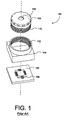
- Fig. 1 illustrates the basic components of a prior art digital camera module 100.
- Digital camera module 100 includes a lens unit 102 with a lens 103 contained therein, a housing 104, a substrate 106, and an image capture device 108.
- Substrate 106 is typically a printed circuit board (PCB) including electrical circuitry and contacts (not shown) of camera module 100.
- Image capture device 108 is mounted on and electrically coupled to PCB 106
- housing 104 is mounted on substrate 106 over image capture device 108.
- Lens unit 102 adjustably mounts to housing 104, by engaging a thread set 110 on lens unit 102 with a complementary thread set 112 in housing 104, so that an image can be focused onto image capture device 108 by lens unit 102.
- Focal adjustment oflens unit 102 is facilitated by thread sets 110 and 112.
- focusing equipment rotates lens unit 102 with respect to housing 104, which adjusts the distance between lens 103 and image capture devices 108.
- lens unit 102 is fixed in position with respect to housing 104 with an adhesive, a thermal weld, or the like.
- camera modules that are focused via thread sets provide for relatively accurate focal adjustments, they suffer from several disadvantages.
- threads are relatively difficult and expensive to manufacture on small optical components.
- small fine threads make screwing the lens unit into the housing a delicate operation.
- sliding friction between threads 110 of lens unit 102 and threads 112 of housing 104 creates particulate debris, which contaminate image capture device 108 or other imaging components of camera module 100 (e.g., infra-red filters, protective covers, other lenses, etc.).
- image capture device 108 or other imaging components of camera module 100 e.g., infra-red filters, protective covers, other lenses, etc.
- Such particulate debris noticeably degrades the quality of the captured images.
- digital camera modules are not easily disassembled and cleaned, particulate matter inside the module is particularly undesirable.
- threaded components are used here as an example, other types of focusing components located inside housing 104 can similarly produce particulate debris that reduces the quality of the captured images.
- U.S. Patent No. 6,426,839 issued to Dou et al. discloses a camera module including a plurality of ramps formed directly on a stationary lens located inside the camera module.
- a rotatable lens carrier (having a separate lens) includes a plurality of legs that engage the ramped surfaces of the stationary lens. Rotating the lens carrier causes the legs of the lens carrier to move up or down the ramped surfaces of the lens, thereby moving the second lens closer to or further from the stationary lens, depending on the direction of rotation.
- U.S. Patent 6,426,839 may help reduce manufacturing cost, the focusing means are still located inside the camera module.
- US 2002/005997 A1 shows an optical lens unit that comprises an optical lens for focusing a light beam, a hollow cylindrical lens holder having, on an inner circumferential surface, a support section contacting one surface of the optical lens and supporting a circumferential part thereof, an elastic member interposed between the support section and the optical lens, and a lens fastener movable along an optical axis of the optical lens, clamping the optical lens jointly with the lens holder, and contacting, at one end, the other surface of the optical lens.
- the lens fastener pushes the circumferential part of the optical lens, thereby to deform the elastic member to adjust the position of a focal point of the optical lens.
- the present invention overcomes the problems associated with the prior art by providing a digital camera module that includes a focus mechanism disposed on the outside of the camera module.
- the invention enables a digital camera module to be focused without creating particulate debris within the camera module. Further, the invention enables a digital camera module to be manufactured and assembled more efficiently in terms of time, cost, quality and yield.
- One digital camera module of the present invention includes an image capture device having a flat top surface, a lens unit, and a housing fixed with respect to the image capture device.
- the housing defines an opening to receive the lens unit and to position the lens unit with respect to the image capture device.
- a focus mechanism is disposed outside of the opening in the housing and is operative to move the lens unit along an axis substantially perpendicular to the flat top surface of the image capture device when the lens unit is rotated about the axis.
- the housing defines a base, surrounding the image capture device, and a cylindrical wall extending upwardly from the base. The opening is defined by the cylindrical wall.
- the focus mechanism includes at least one ramp disposed on one of the housing and the lens unit, and a ramp engaging structure (e.g., a complementary ramp, leg, post, etc.) disposed on the other of the housing and the lens unit.
- a ramp engaging structure e.g., a complementary ramp, leg, post, etc.
- the housing defines at least three ramps and the lens unit defines at least three complementary ramps.
- the ramps can be disposed on the top of the cylindrical wall or on the outer surface of the cylindrical wall.
- one of the cylindrical wall and the lens unit defines a channel and the other of the cylindrical wall and the lens unit defines a guide member engaging the channel.
- the channel and guide member may be formed in the ramped surfaces of the cylindrical wall and the lens unit. The guide member engages the channel to ensure that the lens unit remains centered with respect to the cylindrical wall, thereby preventing contact between the lens unit and the inner surface of the cylindrical wall.
- the lens unit defines a flange that at least partially surrounds the opening in the cylindrical wall when the lens unit is positioned with respect to the image capture device.
- the flange can extend downward to form a sleeve around the outer surface of the cylindrical wall so as to eliminate contact between the upper surface of the cylindrical wall and the lens unit.
- the sleeve includes a portion of the focus mechanism. Examples, of focus mechanisms that can be included on the sleeve include, but are not limited to, ramps, thread sets, grooves, guide pins, cam/followers, or any combination thereof. These mechanism provide a means for focusably mounting said lens unit to said housing at one or more points outside of the opening in the housing.
- the camera modules of the present invention can be used in combination with various camera-hosting devices including, but not limited to, mobile telephones, hand-held electronic organizers, computers, wired or wireless cams, and other types of portable electronic devices.
- the present invention overcomes the problems associated with the prior art by providing a system and method for focusing a digital camera module that is inexpensive to produce and where the focusing mechanism is located outside of the housing that houses imaging components of the camera module, such that particulate debris is less likely to contaminate the imaging components and degrade the quality of the captured images.
- numerous specific details are set forth (e.g., particular examples focus mechanisms, substrate type and attachment, etc.) in order to provide a thorough understanding of the invention. Those skilled in the art will recognize, however, that the invention may be practiced apart from these specific details.
- FIG. 2 is a perspective view of a camera module 200 according to one embodiment of the present invention.
- Camera module 200 is shown mounted on a portion of printed circuit board (PCB) 202 that represents a PCB of a camera hosting device, and communicates electronically with other components of the hosting device via a plurality of electronic traces 204.
- Devices 206 represent electronic components (e.g., passive devices, etc.) that may be mounted directly on substrate 202.
- PCB 202 printed circuit board
- traces 204, and devices 206 are representational in character only.
- Camera module 200 includes an image capture device 208 (not visible in the view of FIG. 2 ), a circuit substrate 210, a housing 212, and a lens unit 214.
- Substrate 210 is mounted on PCB 202 via electrical contacts (not visible in FIG. 2 ) on the bottom of substrate 210.
- Image capture device 208 is mounted on substrate 210 under housing 212.
- Housing 212 includes a base 216 and a cylindrical wall 218.
- Base 216 is substantially the same shape as substrate 210 and, together with substrate 210, encloses image capture device 208 within camera module 200.
- Cylindrical wall 218 extends upwardly from base 216 and defines an opening for receiving and supporting lens unit 214.
- Lens unit 214 is disposed within the top opening of cylindrical wall 218, and is adjustably mounted therein via an external focus mechanism 220.
- focus mechanism 220 includes a plurality of inclined surfaces (ramps) 222 formed on cylindrical wall 218 and a plurality of complementary ramps 224 formed on lens unit 214.
- FIG. 3 is a partially exploded view of camera module 200, showing some additional details not visible in the view of FIG. 2 .
- the components of camera module 200 are aligned along an optical axis 300.
- lens unit 214 and cylindrical wall 218 of housing 212 are coaxial with respect to optical axis 300.
- the imaging surface of image capture device 208 is substantially centered and substantially perpendicular with respect to optical axis 300. Proper optical alignment of lens unit 214 with image capture device 208 facilitates proper focus and lateral alignment of images captured by camera module 200.
- Image capture device 208 includes a flat top surface 301, whereon images are focused and converted into electrical data that is processed by the processing circuitry of image capture device 208 and/or the host device.
- Image capture device 208 further comprises a plurality of die bond pads 302, each of which is electrically coupled to a respective one of a plurality of contact pads 304 on circuit substrate 210 via wire bonding.
- Die bond pads 302 and wire bonded contact pads 304 facilitate the electronic communication of image data between the imaging circuitry of image capture device 208 and the host device via PCB 202.
- image capture device 208 is mounted directly onto circuit substrate 210 with a non-conductive adhesive (e.g., an epoxy). During mounting, image capture device 208 is positioned on circuit substrate 210 using high precision die attaching equipment, such that the optical center of imaging surface 301 is positioned on optical axis 300. Those skilled in the art will be familiar with such chip placement equipment. Further, using an adhesive to mount image capture device 208 to circuit substrate 210 maintains image capture device 208 in a planar relationship with respect to circuit substrate 210 to within +/one-half degree so that surfaces 301 is substantially perpendicular to optical axis 300. Any variation in the thickness of the adhesive can be corrected via focal adjustment of lens unit 214. Alternatively, image capture device 208 can be mounted to substrate 210 via some other means including, but not limited to, flip-chip die bonding.
- a non-conductive adhesive e.g., an epoxy
- Housing 212 is mounted to substrate 210 so as to maintain proper alignment with optical axis 300.
- Circuit substrate 210 includes a plurality (four in this example) of apertures 306, which are located to properly align housing 212 with image capture device 208.
- Housing 212 includes a complementary plurality (only 2 of 4 visible in FIG. 3 ) of posts 308 disposed to engage apertures 306 of substrate 210.
- posts 308 are fixed within apertures 306 of circuit substrate 210 and are secured by any suitable means, such as by an adhesive, a thermal weld, etc..
- posts 308 can extend beyond the bottom surface of circuit substrate 210, and a like plurality of apertures can be provided in PCB 202 for receiving posts 308 and aligning camera module 200 on PCB 202.
- housing base 216 could be mounted directly onto circuit substrate 210 using an adhesive, and posts 308 and apertures could be eliminated. Generally, the mounting of housing 212 onto circuit substrate 210 will be accomplished with automated attaching machines.
- FIG. 3 also shows external focus mechanism 220 that adjustably mounts lens unit 214 to housing 212 in greater detail.
- Cylindrical wall 218 defines a bore 310 for receiving lens unit 214 therein. Bore 310 extends from the open top of cylindrical wall through base 216 such that there is a clear optical path to image capture device 208.
- Ramps 222 are formed on an upper surface 311 of wall 218 outside the cylinder of bore 310.
- Complementary ramps 224 are formed on a lower surface 312 of a flange 314 extending radially from optical unit 214.
- ramps 222 and complementary ramps 224 form a focus mechanism facilitating adjustment of lens unit 214 along axis 300 by displacing lens unit 214 with respect to housing 212.
- rotating lens unit 214 in a counter-clockwise direction raises lens unit 214 with respect to housing 212, thereby increasing the distance between lens unit 214 and image capture device 208.
- Rotating lens unit 214 in a clockwise direction lowers lens unit 214 with respect to housing 212, thereby decreasing the distance between lens unit 214 and image capture device 208.
- an image focused by lens unit 214 can be properly adjusted to lie in the focal plane of image capture device 208.
- ramps 222 and complementary ramps 224 are located outside of the cylinder of bore 310, it is unlikely that any particulate debris caused by focusing lens unit 214 will fall into housing 212 and/or contaminate imaging surface 301 of image capture device 208.
- the present embodiment shows four ramps 222 and four complementary ramps 224, it should be understood that the number of ramps 222 and 224 can be altered without departing from the scope of the present invention.
- the inventors have found that using three ramps results in a good stable focus mechanism, and it is expected that using two ramps would result in an acceptable focus mechanism.
- the focus mechanism can include more than four ramps 224 and 226.
- Lens unit 214 further includes a lens barrel 316 that carries a lens assembly (not shown) therein.
- the particular components of the lens assembly are not shown, because they are not particularly relevant to the present invention.
- known lens assemblies can include one or more lenses, an infrared filter, antireflective coatings, and so on. The particular components will depend on the particular camera type, quality, etc..
- lens unit 214 minimizes contact with the inner surface of 318 of cylindrical wall 218.
- the outer diameter of lens barrel 316 is slightly smaller than the diameter of bore 310 so as to enable lens barrel 316 to rotate within bore 310 without excessive rubbing against the inner surface 318 of cylindrical wall 218. Preventing contact between lens barrel 316 and inner surface 318 further reduces the chance of producing contaminating particulates inside housing 212 during the focusing process.
- FIG. 4 shows a side view of an assembled camera module 200 including an enlarged view of a portion of the centering mechanism that helps prevent contact between lens barrel 316 and inner surface 318 of cylindrical wall 218.
- a centering mechanism prevents the undesirable contact.
- upper surface 311 of cylindrical wall 218 define a guide member 402 (a ridge in this example) that engages a complementary channel 404 formed in lower surface 312 of lens unit 210.
- Guide member 402 and channel 404 guide lens unit 214 as it is rotated and eliminate any horizontal movement between lens barrel 316 and inner surface 318 of cylindrical wall 218. Note that guide member 402 engages channel 404 outside the cylinder of bore 310, further reducing the probability that any generated particulate matter will fall into bore 310.
- lens unit 214 is rotated about optical axis 300 (as indicated by the double-headed arrow) until it is in proper focus. Then, it is fixed into position with an adhesive 406 that is applied between upper surface 311 of cylindrical wall 218 and lower surface 312 of lens unit 214. It should be understood that lens unit 214 can be fixed in position with respect to housing 212 by any suitable alternative means (e.g., a thermal weld, fastener, etc.).
- FIG. 4 also shows that bore 310 is formed all the way through both cylindrical wall 218 and base 216 of housing 212 to provide a clear optical path between lens unit 214 and image capture device 208.
- Base 216 is substantially hollow and extends out outwardly so as to be able to accommodate image capture devices of various sizes.
- image capture device 208 is substantially enclosed within camera module 200.
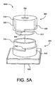
- FIG. 5A shows a partially exploded perspective view of a camera module 500A, which includes an alternate focus mechanism according to another aspect of the present invention.
- Camera module 500A includes an alternate lens unit 502, a housing 504, a circuit substrate 520, and an image capture device (not shown) mounted on substrate 520 and positioned within housing 504.
- the components of camera module 500A are substantially similar to the respective components of camera module 200.
- Lens unit 502 includes a flange 518 having a downwardly extending sleeve 506, which includes at least one ramp 508.
- Housing 504 includes a cylindrical wall with an inner portion 514 for receiving a lens barrel 510 of lens unit 502 therein, and an outer portion 512 having ramp(s) 516 that is/are complementary to ramp(s) 508 of lens unit 502.
- ramp(s) 508 of lens unit 502 slidably engage complementary ramp(s) 516 of outer portion 512.
- rotating lens unit 502 about optical axis 300 causes lens unit 502 to move along optical axis 300 to facilitate focusing.
- lens unit 502 and housing 504 further prevent particulate debris from falling into housing 504.
- ramps 508 and 516 are located outside of cylindrical wall 514 any particulate debris caused by friction between ramps 508 and 516 cannot fall into housing 504.
- cylindrical wall inner portion 514 does not extend high enough to contact flange 518, thereby preventing any frictional contact between the top of inner portion 514 and flange 518.
- the outside surface of inner portion 514 abuts the inside surface of sleeve 506, together functioning as a centering mechanism to prevent frictional contact between inner portion 514 and lens barrel 510.
- ramps 508 and 516 can include guide and channel structures, as discussed above with respect to FIG. 4 .
- sleeve 506 need not be a solid barrel in order to function properly.
- lens unit 502 can alternatively include a plurality of posts or other structures that extend downward from flange 518 so as to engage ramps 516.
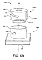
- FIG. 5B is a partially-exploded, perspective view of a camera module 500B, which includes another alternate focus mechanism according to another aspect of the present invention.
- Camera module 500B is similar to camera module 500A except that camera module 500B includes an alternate lens unit 502B and an alternate housing 504B, which are coupled via an alternate focus mechanism.
- lens unit 502B includes an inclined groove 530 formed through sleeve 506B.
- Housing 504B is similar to housing 504, except that housing 504B includes a single-thickness cylindrical wall 532 and a groove follower 534.
- groove follower 534 is a pin that passes through groove 530 and is fixed to cylindrical wall 532.
- lens unit 502B When lens unit 502B is rotated about optical axis 300, lens unit 502B moves along axis 300, thereby facilitating the focusing of lens unit 502B with respect to the image capture device. Note that although only one groove 530 and pin 534 are visible in FIG. 5B , multiple iterations of groove 530 and pin 534 can be included in camera module 500B.
- groove follower 534 can be inserted through groove 530 and into cylindrical wall 532 after lens unit 502B is inserted in housing 504B.
- groove follower 534 can be permanently fixed to housing 504B, and groove 530 can extend to the bottom of sleeve 506B such that groove follower 534 can be inserted into groove 530.
- groove 530 could be formed in the outer surface of (but not totally through) cylindrical wall 532 and groove follower 534 could be formed in sleeve 506B (e.g., a spring loaded pin, a bump on the inner surface 522 of sleeve 506B, etc.).
- groove 530 and groove follower 534 are external to housing 504B, such that any debris created by frictional contact between groove 530 and groove follower 534 will not enter into housing 504B.
- the groove 530 and the groove follower 534 are more robust and less expensive to produce than the threaded prior art camera module 100.
- FIG. 5C shows a partially exploded perspective view of yet another alternate camera module 500C, which includes yet another alternate focus mechanism.
- Camera module 500C is similar to camera module 500B, except that groove 530 and pin 534 are replaced with a thread set 540 and a complementary thread set 542, respectively.
- thread set 540 is formed on the inner surface 522 of sleeve 506.
- Complementary thread set 542 is formed on the outer surface of a cylindrical wall 544 of alternate housing 504C.
- threads as a focus mechanism is considered to be less desirable from a manufacturing and assembly perspective.
- threads may provide a desired advantage (e.g., more precise focus, etc.).
- the present invention still provides an advantage over the devices of the prior art.
- the image capture device will not be exposed to any debris created by frictional contact between thread sets 540 and 542 during the focus operation.
Landscapes
- Engineering & Computer Science (AREA)
- Multimedia (AREA)
- Signal Processing (AREA)
- Physics & Mathematics (AREA)
- General Physics & Mathematics (AREA)
- Studio Devices (AREA)
- Lens Barrels (AREA)
- Camera Bodies And Camera Details Or Accessories (AREA)
Claims (26)
- Kameramodul (200; 500) mit:einem Schaltungssubstrat (210);einer Bildaufnahmeeinrichtung (208) mit einer flachen oberen Oberfläche, wobei die Bildaufnahmeeinrichtung (208) auf dem Schaltungssubstrat (210) angeordnet ist;einer Linseneinheit (214, 502) mit einer Linsentrommel (316), die die Linse trägt;einem Gehäuse (212; 504), das in Bezug auf die Bildaufnahmeeinrichtung (208) fixiert ist und an dem Schaltungssubstrat angeordnet ist, wobei das Gehäuse eine Öffnung definiert, die hierin die Linsentrommel (316) aufnimmt, wobei das Gehäuse (212; 504) die Linseneinheit bezogen auf die Bildaufnahmeeinrichtung positioniert; undeiner Fokussiermechanik (220), die außerhalb der Öffnung angeordnet ist undfunktionsfähig ist, um die Linseneinheit (214; 502) entlang einer Achse (300) zu bewegen, die im Wesentlichen senkrecht zu der flachen oberen Oberfläche der Bildaufnahmeeinrichtung (208) ist, wenn sich die Linseneinheit um die Achse (300) dreht.
- Kameramodul nach Anspruch 1, wobei das Gehäuse eine Basis (216) aufweist, die die Bildaufnahmeeinrichtung umgibt.
- Kameramodul nach Anspruch 1, wobei die Fokussiermechanik (220) aufweist:eine Rampe (222; 516; 534; 542), die entweder auf dem Gehäuse (212; 504) oder auf der Linseneinheit angeordnet ist; undein mit der Rampe zusammenwirkender Aufbau (224; 508; 530; 540), der an dem anderen Element von Gehäuse und der Linseneinheit (214; 502) angeordnet ist.
- Kameramodul nach Anspruch 3, wobei der mit der Rampe zusammenwirkende Aufbau (224; 508; 530; 540) eine zweite Rampe aufweist, die komplementär zu der Rampe ist.
- Kameramodul nach Anspruch 1, wobei das Gehäuse (212; 504) eine zylindrische Wand (218; 512, 514; 532; 544) aufweist, die die Öffnung definiert.
- Kameramodul nach Anspruch 5, wobei die zylindrische Wand (218) eine obere Oberfläche (311) aufweist, die zumindest einen Teil der Fokussiermechanik (220) definiert.
- Kameramodul nach Anspruch 6, wobei:die Fokussiermechanik (220) zumindest eine Rampe (220) aufweist; unddie obere Oberfläche (311) der zylindrischen Wand die zumindest eine Rampe (222) definiert.
- Kameramodul nach Anspruch 7, wobei:die Fokussiermechanik (220) des Weiteren eine komplementäre Rampe (224) aufweist, die gleitend mit der zumindest einen Rampe (222) zusammenwirkt; unddie Linseneinheit (214) die zumindest eine komplementäre Rampe (224) aufweist.
- Kameramodul nach Anspruch 7, wobei die Fokussiermechanik (220) mindestens drei Rampen aufweist.
- Kameramodul nach Anspruch 5, wobei zumindest ein Abschnitt der Fokussiermechanik (220) auf einer äußeren Oberfläche der zylindrischen Wand (512, 514; 532; 544) angeordnet ist.
- Kameramodul nach Anspruch 10, wobei:die Fokussiermechanik zumindest eine Rampe (516) aufweist; unddie äußere Oberfläche der zylindrischen Wand die zumindest eine Rampe (516) definiert.
- Kameramodul nach Anspruch 11, wobei:die Fokussiermechanik (220) zumindest eine weitere komplementäre Rampe (508) aufweist, die gleitend mit der zumindest einen Rampe (516) zusammenwirkt; unddie Linseneinheit (502) die zumindest eine komplementäre Rampe (508) aufweist.
- Kameramodul nach Anspruch 11, wobei der Fokusmechanismus zumindest drei Rampen aufweist.
- Kameramodul nach Anspruch 5, wobei:entweder die zylindrische Wand oder die Linseneinheit einen Kanal (404) definiert; unddas andere Element von zylindrischer Wand und der Linseneinheit ein Führungselement (402) definiert, das mit den Kanälen (404) zusammenwirkt, wobei das Führungselement (402) funktionsfähig ist, um zu verhindern, dass die Linseneinheit eine innere Oberfläche der zylindrischen Wand kontaktiert.
- Kameramodul nach Anspruch 5, wobei die Linseneinheit des Weiteren eine Hülse (506) aufweist, die zumindest teilweise die zylindrische Wand umgibt, wenn die Linseneinheit (502) bezogen auf die Bildaufnahmeeinrichtung (208) positioniert wird.
- Kameramodul nach Anspruch 15, wobei die Hülse (506) zumindest einen Abschnitt der Fokussiermechanik (220) aufweist.
- Kameramodul nach Anspruch 16, wobei der Abschnitt der Fokussiermechanik (220) eine Rampe (508) ist, die funktionsfähig ist, um mit einer komplementären Rampe (516) zusammenzuwirken, die an der Außenseite der zylindrischen Wand (512, 514) angeordnet ist.
- Kameramodul nach Anspruch 16, wobei der Abschnitt der Fokussiermechanik (220) eine Gewindegruppe (540) ist, die funktionsfähig ist, um mit einer komplementären Gewindegruppe (542) zusammenzuwirken, die an der Außenseite der zylindrischen Wand (544) angeordnet ist.
- Kameramodul nach Anspruch 16, wobei der Abschnitt der Fokussiermechanik (220) eine Nut (530) oder einen Nutfolger aufweist, die/der funktionsfähig ist, um mit dem anderen Element von Nut und Nutfolger (534) zusammenzuwirken, das an der Außenseite der zylindrischen Wand (532) angeordnet ist.
- Kameramodul nach Anspruch 1, wobei die Fokussiermechanik aufweist:eine Nut (530), die entweder in dem Gehäuse oder der Linseneinheit ausgebildet ist; undeinen Nutfolger (534), der in dem anderen Element von Gehäuse und Linseneinheit ausgebildet ist,wobei die Nut (530) den Nutfolger (534) aufnimmt, wenn die Linseneinheit bezogen auf die Bildaufnahmeeinrichtung positioniert wird.
- Kameramodul nach Anspruch 1, wobei die Fokussiermechanik aufweist:eine Gewindegruppe (540), die an dem Gehäuse außerhalb der Öffnung ausgebildet ist; undeine komplementäre Gewindegruppe (542), die an der Linseneinheit ausgebildet ist, um mit der Gewindegruppe des Gehäuses zusammenzuwirken.
- Kameramodul nach Anspruch 1, wobei:das Gehäuse des Weiteren eine Basis (216) aufweist, die die Bildaufnahmeeinrichtung umgibt, und eine zylindrische Wand (218), die die Öffnung definiert;wobei die zylindrische Wand eine obere Oberfläche (311) aufweist, die zumindest eine Rampe (222) definiert, undwobei die Linseneinheit (214) zumindest eine komplementäre Rampe (224) aufweist, um gleitend mit der zumindest einen Rampe (222) zusammenzuwirken, die von der oberen Oberfläche (311) der zylindrischen Wand definiert ist.
- Kameramodul nach Anspruch 1, wobei:das Gehäuse eine zylindrische Bohrung (310) definiert, die funktionsfähig ist, um die Linseneinheit aufzunehmen; undder obere Umfang der Bohrung die Öffnung definiert.
- Kameraaufnehmende Einrichtung mit einem Kameramodul (200; 500) nach Anspruch 1.
- Kameramodul nach Anspruch 1, wobei:die Linsentrommel (316) zwischen der Linse und einer inneren Oberfläche (318) des Gehäuses (212; 504) angeordnet ist; unddie Linsentrommel (316) einen Durchmesser hat, der so dimensioniert ist, dass ein Kontakt zwischen einer äußeren Oberfläche der Linsentrommel (316) und einer inneren Oberfläche (318) des Gehäuses (212; 504) verhindert wird.
- Kameramodul nach Anspruch 1, wobei:das Gehäuse (212; 504) dauerhaft an dem Schaltungssubstrat (210) befestigt ist; unddie Linsentrommel (316) dauerhaft an dem Gehäuse (212; 504) befestigt ist.
Applications Claiming Priority (2)
| Application Number | Priority Date | Filing Date | Title |
|---|---|---|---|
| US11/228,010 US7684689B2 (en) | 2005-09-15 | 2005-09-15 | External adjustment mechanism for a camera lens and electronic imager |
| PCT/US2006/035852 WO2007035418A2 (en) | 2005-09-15 | 2006-09-14 | External adjustment mechanism for a camera lens and electronic imager |
Publications (3)
| Publication Number | Publication Date |
|---|---|
| EP1932045A2 EP1932045A2 (de) | 2008-06-18 |
| EP1932045A4 EP1932045A4 (de) | 2010-10-06 |
| EP1932045B1 true EP1932045B1 (de) | 2013-07-31 |
Family
ID=37855218
Family Applications (1)
| Application Number | Title | Priority Date | Filing Date |
|---|---|---|---|
| EP06803604.5A Not-in-force EP1932045B1 (de) | 2005-09-15 | 2006-09-14 | Externer justierungsmechanismus für eine kameralinse und elektronischer bildgeber |
Country Status (5)
| Country | Link |
|---|---|
| US (1) | US7684689B2 (de) |
| EP (1) | EP1932045B1 (de) |
| CN (1) | CN101300515B (de) |
| TW (1) | TWI361947B (de) |
| WO (1) | WO2007035418A2 (de) |
Families Citing this family (33)
| Publication number | Priority date | Publication date | Assignee | Title |
|---|---|---|---|---|
| DE102005022594A1 (de) * | 2004-05-18 | 2006-01-19 | Citizen Electronics Co., Ltd., Fujiyoshida | Bildgebende Vorrichtung |
| US7469100B2 (en) | 2005-10-03 | 2008-12-23 | Flextronics Ap Llc | Micro camera module with discrete manual focal positions |
| CN1964607A (zh) * | 2005-11-11 | 2007-05-16 | 鸿富锦精密工业(深圳)有限公司 | 便携式电子产品 |
| US7983556B2 (en) * | 2006-11-03 | 2011-07-19 | Flextronics Ap Llc | Camera module with contamination reduction feature |
| CN101231371B (zh) * | 2007-01-24 | 2010-06-02 | 鸿富锦精密工业(深圳)有限公司 | 相机模组 |
| CN101261347A (zh) * | 2007-03-09 | 2008-09-10 | 鸿富锦精密工业(深圳)有限公司 | 相机模组及其制造方法 |
| JP2010525412A (ja) * | 2007-04-24 | 2010-07-22 | フレックストロニクス エーピー エルエルシー | 底部にキャビティを備えるウエハーレベル光学部品とフリップチップ組立を用いた小型フォームファクタモジュール |
| JP2010525413A (ja) * | 2007-04-24 | 2010-07-22 | フレックストロニクス エーピー エルエルシー | ウエハーレベル光学部品を用いた自動焦点/ズームモジュール |
| US7825985B2 (en) * | 2007-07-19 | 2010-11-02 | Flextronics Ap, Llc | Camera module back-focal length adjustment method and ultra compact components packaging |
| TWI422947B (zh) * | 2007-09-14 | 2014-01-11 | Hon Hai Prec Ind Co Ltd | 具有相機模組之便攜式電子裝置 |
| US7830624B2 (en) * | 2007-10-18 | 2010-11-09 | Flextronics Ap, Llc | Laser bonding camera modules to lock focus |
| TWM341858U (en) * | 2007-12-19 | 2008-10-01 | Largan Precision Co Ltd | Auto-focus module |
| US9118825B2 (en) * | 2008-02-22 | 2015-08-25 | Nan Chang O-Film Optoelectronics Technology Ltd. | Attachment of wafer level optics |
| US9419032B2 (en) * | 2009-08-14 | 2016-08-16 | Nanchang O-Film Optoelectronics Technology Ltd | Wafer level camera module with molded housing and method of manufacturing |
| TWI453492B (zh) * | 2009-11-02 | 2014-09-21 | Hon Hai Prec Ind Co Ltd | 鏡頭模組 |
| DE102011011527A1 (de) * | 2011-02-17 | 2012-08-23 | Conti Temic Microelectronic Gmbh | Kameramodul |
| US8545114B2 (en) | 2011-03-11 | 2013-10-01 | Digitaloptics Corporation | Auto focus-zoom actuator or camera module contamination reduction feature with integrated protective membrane |
| US9178093B2 (en) | 2011-07-06 | 2015-11-03 | Flextronics Ap, Llc | Solar cell module on molded lead-frame and method of manufacture |
| KR20140054967A (ko) * | 2012-10-30 | 2014-05-09 | 엘지이노텍 주식회사 | 카메라 모듈 |
| TWI501620B (zh) * | 2013-07-29 | 2015-09-21 | Cipherlab Co Ltd | 光學組件及使用其之影像擷取器 |
| US9810574B2 (en) * | 2013-08-29 | 2017-11-07 | The United States Of America As Represented By The Secretary Of The Army | Protective device for an imager |
| CN104698564B (zh) * | 2013-12-06 | 2017-05-24 | 中国科学院西安光学精密机械研究所 | 一种空间相机基准镜位姿调节装置 |
| CN104808319B (zh) * | 2015-01-23 | 2017-07-25 | 玉晶光电(厦门)有限公司 | 光学成像镜头及应用此镜头之电子装置 |
| CN108333707B (zh) * | 2017-01-19 | 2020-12-08 | 信泰光学(深圳)有限公司 | 变倍装置 |
| TWI650606B (zh) * | 2017-10-31 | 2019-02-11 | 鴻海精密工業股份有限公司 | 相機模組 |
| CN109917605B (zh) * | 2017-12-13 | 2021-06-01 | 三赢科技(深圳)有限公司 | 镜头模组 |
| US10899275B2 (en) * | 2018-06-27 | 2021-01-26 | Magna Electronics Inc. | Vehicular camera with PCB focus tuning |
| CN110753170B (zh) * | 2019-09-09 | 2024-08-30 | 浙江舜宇智领技术有限公司 | 一种摄像模组及组装方法 |
| US11428896B2 (en) | 2019-10-07 | 2022-08-30 | Hand Held Products, Inc. | Housing of an image capturing device |
| CN110769141B (zh) * | 2019-11-20 | 2024-06-07 | 浙江舜宇智领技术有限公司 | 一种车载摄像模组 |
| US12174448B2 (en) | 2020-06-08 | 2024-12-24 | Magna Electronics Inc. | Vehicular camera assembly process using welding to secure lens relative to camera image plane |
| US11635672B2 (en) * | 2020-06-08 | 2023-04-25 | Magna Electronics Inc. | Vehicular camera assembly process using welding to secure lens relative to camera image plane |
| US12422691B2 (en) * | 2022-05-17 | 2025-09-23 | Magna Electronics Inc. | Vehicular camera assembly with lens barrel welded at imager housing |
Family Cites Families (20)
| Publication number | Priority date | Publication date | Assignee | Title |
|---|---|---|---|---|
| DE1911372B1 (de) * | 1969-03-06 | 1971-01-21 | Balda Werke Photographische | Justierbares Objektiv |
| JPS57179808A (en) * | 1981-04-30 | 1982-11-05 | Fuji Xerox Co Ltd | Back focus adjusting device for lens of optical system |
| JPH0622806Y2 (ja) * | 1989-09-27 | 1994-06-15 | パイオニア株式会社 | レンズフレーム |
| JPH0743689Y2 (ja) * | 1990-10-17 | 1995-10-09 | パイオニア株式会社 | レンズフレーム |
| JPH09113787A (ja) * | 1995-10-24 | 1997-05-02 | Olympus Optical Co Ltd | レンズの位置調節機構 |
| JPH10321827A (ja) * | 1997-05-16 | 1998-12-04 | Sony Corp | 撮像装置及びカメラ |
| US5825559A (en) * | 1997-06-27 | 1998-10-20 | Eastman Kodak Company | Optical assembly having a dual purpose focus |
| US6351288B1 (en) * | 1997-06-27 | 2002-02-26 | Eastman Kodak Company | Sensor tilt control for a digital camera |
| JP3651580B2 (ja) | 2000-04-07 | 2005-05-25 | 三菱電機株式会社 | 撮像装置及びその製造方法 |
| JP4405062B2 (ja) * | 2000-06-16 | 2010-01-27 | 株式会社ルネサステクノロジ | 固体撮像装置 |
| US6476985B2 (en) * | 2000-06-27 | 2002-11-05 | Milestone Co., Ltd. | Image pickup lens unit |
| US6426839B2 (en) * | 2000-06-27 | 2002-07-30 | Milestone Co., Ltd. | Image pickup lens unit |
| TWI221207B (en) | 2000-07-17 | 2004-09-21 | Toshiba Corp | Optical lens unit having a mechanism for adjusting the focal point of the optical lens |
| JP3954332B2 (ja) * | 2000-07-17 | 2007-08-08 | 株式会社東芝 | 光学レンズユニット及びカメラモジュール |
| US6359740B1 (en) * | 2000-09-20 | 2002-03-19 | San Hua Tien Precision Circuit Co., Ltd. | Image capturing device |
| US6654187B2 (en) * | 2001-07-16 | 2003-11-25 | Alex Ning | Camera lens carrier for circuit board mounting |
| TW524318U (en) * | 2002-01-18 | 2003-03-11 | Nucam Cororation | Zoom lens control mechanism |
| US20050190283A1 (en) * | 2004-02-24 | 2005-09-01 | Carmel Ish-Shalom | Method and apparatus for macro-focus |
| CN1892402A (zh) * | 2005-07-09 | 2007-01-10 | 鸿富锦精密工业(深圳)有限公司 | 数码相机模块 |
| US7469100B2 (en) * | 2005-10-03 | 2008-12-23 | Flextronics Ap Llc | Micro camera module with discrete manual focal positions |
-
2005
- 2005-09-15 US US11/228,010 patent/US7684689B2/en not_active Expired - Lifetime
-
2006
- 2006-08-22 TW TW095130828A patent/TWI361947B/zh active
- 2006-09-14 WO PCT/US2006/035852 patent/WO2007035418A2/en not_active Ceased
- 2006-09-14 EP EP06803604.5A patent/EP1932045B1/de not_active Not-in-force
- 2006-09-14 CN CN200680040738.4A patent/CN101300515B/zh not_active Expired - Fee Related
Also Published As
| Publication number | Publication date |
|---|---|
| EP1932045A2 (de) | 2008-06-18 |
| WO2007035418A3 (en) | 2007-12-06 |
| TW200710529A (en) | 2007-03-16 |
| US7684689B2 (en) | 2010-03-23 |
| CN101300515B (zh) | 2014-04-23 |
| US20070058964A1 (en) | 2007-03-15 |
| CN101300515A (zh) | 2008-11-05 |
| EP1932045A4 (de) | 2010-10-06 |
| TWI361947B (en) | 2012-04-11 |
| WO2007035418A2 (en) | 2007-03-29 |
Similar Documents
| Publication | Publication Date | Title |
|---|---|---|
| US7684689B2 (en) | External adjustment mechanism for a camera lens and electronic imager | |
| US7983556B2 (en) | Camera module with contamination reduction feature | |
| KR101983169B1 (ko) | 렌즈 모듈, 렌즈 모듈의 제조 방법 및 렌즈 모듈을 포함하는 카메라 모듈 | |
| US7729606B2 (en) | Lens module and digital camera module using same | |
| US7450834B2 (en) | Lens unit and imaging apparatus | |
| US5825559A (en) | Optical assembly having a dual purpose focus | |
| US7602439B2 (en) | Lens unit and imaging apparatus | |
| US7492538B2 (en) | Camera module | |
| US12181728B2 (en) | Lens assembly, camera module, and optical device | |
| CN108369365B (zh) | 透镜驱动装置以及包括其的摄像装置模块 | |
| US20120288272A1 (en) | Camera module with threadless lens barrel engagement design | |
| WO2020246465A1 (ja) | レンズ駆動装置、カメラモジュール、及びカメラ搭載装置 | |
| US7605864B2 (en) | Image pickup apparatus and electronics apparatus mounting the same | |
| US7359130B1 (en) | Lens mount and alignment method | |
| CN115201991B (zh) | 镜头调焦设备 | |
| JP2007041141A (ja) | レンズ保持構造体、レンズ位置調整方法およびカメラモジュール | |
| CN111679442B (zh) | 光学调校系统和调焦装置 | |
| CN110967799B (zh) | 光学镜头和摄像模组及其应用 |
Legal Events
| Date | Code | Title | Description |
|---|---|---|---|
| PUAI | Public reference made under article 153(3) epc to a published international application that has entered the european phase |
Free format text: ORIGINAL CODE: 0009012 |
|
| 17P | Request for examination filed |
Effective date: 20080327 |
|
| AK | Designated contracting states |
Kind code of ref document: A2 Designated state(s): AT BE BG CH CY CZ DE DK EE ES FI FR GB GR HU IE IS IT LI LT LU LV MC NL PL PT RO SE SI SK TR |
|
| AX | Request for extension of the european patent |
Extension state: AL BA HR MK RS |
|
| A4 | Supplementary search report drawn up and despatched |
Effective date: 20100906 |
|
| DAX | Request for extension of the european patent (deleted) | ||
| GRAP | Despatch of communication of intention to grant a patent |
Free format text: ORIGINAL CODE: EPIDOSNIGR1 |
|
| RIN1 | Information on inventor provided before grant (corrected) |
Inventor name: SHANGGUAN, DONGKAI Inventor name: BOGUE, ELAINE, B. Inventor name: MORTON, RAY, H. Inventor name: TAM, SAMUEL, WAISING Inventor name: KALE, VIDYADHAR, SITARAM |
|
| RAP1 | Party data changed (applicant data changed or rights of an application transferred) |
Owner name: DIGITALOPTICS CORPORATION |
|
| GRAS | Grant fee paid |
Free format text: ORIGINAL CODE: EPIDOSNIGR3 |
|
| GRAA | (expected) grant |
Free format text: ORIGINAL CODE: 0009210 |
|
| AK | Designated contracting states |
Kind code of ref document: B1 Designated state(s): AT BE BG CH CY CZ DE DK EE ES FI FR GB GR HU IE IS IT LI LT LU LV MC NL PL PT RO SE SI SK TR |
|
| REG | Reference to a national code |
Ref country code: GB Ref legal event code: FG4D Ref country code: CH Ref legal event code: EP |
|
| REG | Reference to a national code |
Ref country code: AT Ref legal event code: REF Ref document number: 624965 Country of ref document: AT Kind code of ref document: T Effective date: 20130815 |
|
| REG | Reference to a national code |
Ref country code: IE Ref legal event code: FG4D |
|
| REG | Reference to a national code |
Ref country code: DE Ref legal event code: R096 Ref document number: 602006037662 Country of ref document: DE Effective date: 20130919 |
|
| REG | Reference to a national code |
Ref country code: AT Ref legal event code: MK05 Ref document number: 624965 Country of ref document: AT Kind code of ref document: T Effective date: 20130731 |
|
| REG | Reference to a national code |
Ref country code: NL Ref legal event code: VDEP Effective date: 20130731 |
|
| REG | Reference to a national code |
Ref country code: LT Ref legal event code: MG4D |
|
| PG25 | Lapsed in a contracting state [announced via postgrant information from national office to epo] |
Ref country code: CY Free format text: LAPSE BECAUSE OF FAILURE TO SUBMIT A TRANSLATION OF THE DESCRIPTION OR TO PAY THE FEE WITHIN THE PRESCRIBED TIME-LIMIT Effective date: 20130724 Ref country code: AT Free format text: LAPSE BECAUSE OF FAILURE TO SUBMIT A TRANSLATION OF THE DESCRIPTION OR TO PAY THE FEE WITHIN THE PRESCRIBED TIME-LIMIT Effective date: 20130731 Ref country code: IS Free format text: LAPSE BECAUSE OF FAILURE TO SUBMIT A TRANSLATION OF THE DESCRIPTION OR TO PAY THE FEE WITHIN THE PRESCRIBED TIME-LIMIT Effective date: 20131130 Ref country code: SE Free format text: LAPSE BECAUSE OF FAILURE TO SUBMIT A TRANSLATION OF THE DESCRIPTION OR TO PAY THE FEE WITHIN THE PRESCRIBED TIME-LIMIT Effective date: 20130731 Ref country code: PT Free format text: LAPSE BECAUSE OF FAILURE TO SUBMIT A TRANSLATION OF THE DESCRIPTION OR TO PAY THE FEE WITHIN THE PRESCRIBED TIME-LIMIT Effective date: 20131202 Ref country code: BE Free format text: LAPSE BECAUSE OF FAILURE TO SUBMIT A TRANSLATION OF THE DESCRIPTION OR TO PAY THE FEE WITHIN THE PRESCRIBED TIME-LIMIT Effective date: 20130731 Ref country code: LT Free format text: LAPSE BECAUSE OF FAILURE TO SUBMIT A TRANSLATION OF THE DESCRIPTION OR TO PAY THE FEE WITHIN THE PRESCRIBED TIME-LIMIT Effective date: 20130731 |
|
| PG25 | Lapsed in a contracting state [announced via postgrant information from national office to epo] |
Ref country code: GR Free format text: LAPSE BECAUSE OF FAILURE TO SUBMIT A TRANSLATION OF THE DESCRIPTION OR TO PAY THE FEE WITHIN THE PRESCRIBED TIME-LIMIT Effective date: 20131101 Ref country code: NL Free format text: LAPSE BECAUSE OF FAILURE TO SUBMIT A TRANSLATION OF THE DESCRIPTION OR TO PAY THE FEE WITHIN THE PRESCRIBED TIME-LIMIT Effective date: 20130731 Ref country code: SI Free format text: LAPSE BECAUSE OF FAILURE TO SUBMIT A TRANSLATION OF THE DESCRIPTION OR TO PAY THE FEE WITHIN THE PRESCRIBED TIME-LIMIT Effective date: 20130731 Ref country code: LV Free format text: LAPSE BECAUSE OF FAILURE TO SUBMIT A TRANSLATION OF THE DESCRIPTION OR TO PAY THE FEE WITHIN THE PRESCRIBED TIME-LIMIT Effective date: 20130731 Ref country code: FI Free format text: LAPSE BECAUSE OF FAILURE TO SUBMIT A TRANSLATION OF THE DESCRIPTION OR TO PAY THE FEE WITHIN THE PRESCRIBED TIME-LIMIT Effective date: 20130731 Ref country code: PL Free format text: LAPSE BECAUSE OF FAILURE TO SUBMIT A TRANSLATION OF THE DESCRIPTION OR TO PAY THE FEE WITHIN THE PRESCRIBED TIME-LIMIT Effective date: 20130731 |
|
| PG25 | Lapsed in a contracting state [announced via postgrant information from national office to epo] |
Ref country code: CY Free format text: LAPSE BECAUSE OF FAILURE TO SUBMIT A TRANSLATION OF THE DESCRIPTION OR TO PAY THE FEE WITHIN THE PRESCRIBED TIME-LIMIT Effective date: 20130731 |
|
| PG25 | Lapsed in a contracting state [announced via postgrant information from national office to epo] |
Ref country code: MC Free format text: LAPSE BECAUSE OF FAILURE TO SUBMIT A TRANSLATION OF THE DESCRIPTION OR TO PAY THE FEE WITHIN THE PRESCRIBED TIME-LIMIT Effective date: 20130731 Ref country code: DK Free format text: LAPSE BECAUSE OF FAILURE TO SUBMIT A TRANSLATION OF THE DESCRIPTION OR TO PAY THE FEE WITHIN THE PRESCRIBED TIME-LIMIT Effective date: 20130731 Ref country code: CZ Free format text: LAPSE BECAUSE OF FAILURE TO SUBMIT A TRANSLATION OF THE DESCRIPTION OR TO PAY THE FEE WITHIN THE PRESCRIBED TIME-LIMIT Effective date: 20130731 Ref country code: SK Free format text: LAPSE BECAUSE OF FAILURE TO SUBMIT A TRANSLATION OF THE DESCRIPTION OR TO PAY THE FEE WITHIN THE PRESCRIBED TIME-LIMIT Effective date: 20130731 Ref country code: EE Free format text: LAPSE BECAUSE OF FAILURE TO SUBMIT A TRANSLATION OF THE DESCRIPTION OR TO PAY THE FEE WITHIN THE PRESCRIBED TIME-LIMIT Effective date: 20130731 Ref country code: RO Free format text: LAPSE BECAUSE OF FAILURE TO SUBMIT A TRANSLATION OF THE DESCRIPTION OR TO PAY THE FEE WITHIN THE PRESCRIBED TIME-LIMIT Effective date: 20130731 |
|
| REG | Reference to a national code |
Ref country code: CH Ref legal event code: PL |
|
| PG25 | Lapsed in a contracting state [announced via postgrant information from national office to epo] |
Ref country code: ES Free format text: LAPSE BECAUSE OF FAILURE TO SUBMIT A TRANSLATION OF THE DESCRIPTION OR TO PAY THE FEE WITHIN THE PRESCRIBED TIME-LIMIT Effective date: 20130731 Ref country code: IT Free format text: LAPSE BECAUSE OF FAILURE TO SUBMIT A TRANSLATION OF THE DESCRIPTION OR TO PAY THE FEE WITHIN THE PRESCRIBED TIME-LIMIT Effective date: 20130731 |
|
| PLBE | No opposition filed within time limit |
Free format text: ORIGINAL CODE: 0009261 |
|
| STAA | Information on the status of an ep patent application or granted ep patent |
Free format text: STATUS: NO OPPOSITION FILED WITHIN TIME LIMIT |
|
| REG | Reference to a national code |
Ref country code: IE Ref legal event code: MM4A |
|
| 26N | No opposition filed |
Effective date: 20140502 |
|
| PG25 | Lapsed in a contracting state [announced via postgrant information from national office to epo] |
Ref country code: IE Free format text: LAPSE BECAUSE OF NON-PAYMENT OF DUE FEES Effective date: 20130914 Ref country code: CH Free format text: LAPSE BECAUSE OF NON-PAYMENT OF DUE FEES Effective date: 20130930 Ref country code: LI Free format text: LAPSE BECAUSE OF NON-PAYMENT OF DUE FEES Effective date: 20130930 |
|
| REG | Reference to a national code |
Ref country code: DE Ref legal event code: R097 Ref document number: 602006037662 Country of ref document: DE Effective date: 20140502 |
|
| REG | Reference to a national code |
Ref country code: GB Ref legal event code: 732E Free format text: REGISTERED BETWEEN 20150220 AND 20150225 |
|
| REG | Reference to a national code |
Ref country code: FR Ref legal event code: TP Owner name: NANCHNAG O-FILM OPTOELECTRONICS TECHNOLOGY LTD, CN Effective date: 20150311 |
|
| REG | Reference to a national code |
Ref country code: DE Ref legal event code: R082 Ref document number: 602006037662 Country of ref document: DE Representative=s name: MICHALSKI HUETTERMANN & PARTNER PATENTANWAELTE, DE Ref country code: DE Ref legal event code: R081 Ref document number: 602006037662 Country of ref document: DE Owner name: NANCHANG O-FILM OPTOELECTRONICS TECHNOLOGY LTD, CN Free format text: FORMER OWNER: DIGITALOPTICS CORPORATION, SAN JOSE, CALIF., US |
|
| PG25 | Lapsed in a contracting state [announced via postgrant information from national office to epo] |
Ref country code: TR Free format text: LAPSE BECAUSE OF FAILURE TO SUBMIT A TRANSLATION OF THE DESCRIPTION OR TO PAY THE FEE WITHIN THE PRESCRIBED TIME-LIMIT Effective date: 20130731 |
|
| PG25 | Lapsed in a contracting state [announced via postgrant information from national office to epo] |
Ref country code: BG Free format text: LAPSE BECAUSE OF FAILURE TO SUBMIT A TRANSLATION OF THE DESCRIPTION OR TO PAY THE FEE WITHIN THE PRESCRIBED TIME-LIMIT Effective date: 20130731 Ref country code: HU Free format text: LAPSE BECAUSE OF FAILURE TO SUBMIT A TRANSLATION OF THE DESCRIPTION OR TO PAY THE FEE WITHIN THE PRESCRIBED TIME-LIMIT; INVALID AB INITIO Effective date: 20060914 Ref country code: LU Free format text: LAPSE BECAUSE OF NON-PAYMENT OF DUE FEES Effective date: 20130914 |
|
| REG | Reference to a national code |
Ref country code: FR Ref legal event code: PLFP Year of fee payment: 11 |
|
| REG | Reference to a national code |
Ref country code: FR Ref legal event code: PLFP Year of fee payment: 12 |
|
| REG | Reference to a national code |
Ref country code: FR Ref legal event code: PLFP Year of fee payment: 13 |
|
| PGFP | Annual fee paid to national office [announced via postgrant information from national office to epo] |
Ref country code: FR Payment date: 20210921 Year of fee payment: 16 |
|
| PGFP | Annual fee paid to national office [announced via postgrant information from national office to epo] |
Ref country code: DE Payment date: 20210920 Year of fee payment: 16 Ref country code: GB Payment date: 20210920 Year of fee payment: 16 |
|
| REG | Reference to a national code |
Ref country code: DE Ref legal event code: R119 Ref document number: 602006037662 Country of ref document: DE |
|
| GBPC | Gb: european patent ceased through non-payment of renewal fee |
Effective date: 20220914 |
|
| PG25 | Lapsed in a contracting state [announced via postgrant information from national office to epo] |
Ref country code: FR Free format text: LAPSE BECAUSE OF NON-PAYMENT OF DUE FEES Effective date: 20220930 Ref country code: DE Free format text: LAPSE BECAUSE OF NON-PAYMENT OF DUE FEES Effective date: 20230401 |
|
| PG25 | Lapsed in a contracting state [announced via postgrant information from national office to epo] |
Ref country code: GB Free format text: LAPSE BECAUSE OF NON-PAYMENT OF DUE FEES Effective date: 20220914 |