EP1931589B1 - Lifting sling system - Google Patents
Lifting sling system Download PDFInfo
- Publication number
- EP1931589B1 EP1931589B1 EP05791705.6A EP05791705A EP1931589B1 EP 1931589 B1 EP1931589 B1 EP 1931589B1 EP 05791705 A EP05791705 A EP 05791705A EP 1931589 B1 EP1931589 B1 EP 1931589B1
- Authority
- EP
- European Patent Office
- Prior art keywords
- lifting
- sling
- lifting sling
- units
- dual
- Prior art date
- Legal status (The legal status is an assumption and is not a legal conclusion. Google has not performed a legal analysis and makes no representation as to the accuracy of the status listed.)
- Active
Links
- 238000010168 coupling process Methods 0.000 claims description 37
- 238000005859 coupling reaction Methods 0.000 claims description 37
- 230000008878 coupling Effects 0.000 claims description 33
- 230000009977 dual effect Effects 0.000 claims description 26
- 239000000835 fiber Substances 0.000 claims description 5
- 238000004904 shortening Methods 0.000 claims description 3
- 239000000463 material Substances 0.000 claims description 2
- 101100456831 Caenorhabditis elegans sams-5 gene Proteins 0.000 description 5
- 239000000969 carrier Substances 0.000 description 3
- 230000000712 assembly Effects 0.000 description 1
- 238000000429 assembly Methods 0.000 description 1
- 230000006378 damage Effects 0.000 description 1
- 230000004069 differentiation Effects 0.000 description 1
- 239000000446 fuel Substances 0.000 description 1
- 238000007689 inspection Methods 0.000 description 1
- 230000007774 longterm Effects 0.000 description 1
- 239000002184 metal Substances 0.000 description 1
- 238000000034 method Methods 0.000 description 1
- 230000000007 visual effect Effects 0.000 description 1
Images


Classifications
-
- B—PERFORMING OPERATIONS; TRANSPORTING
- B66—HOISTING; LIFTING; HAULING
- B66C—CRANES; LOAD-ENGAGING ELEMENTS OR DEVICES FOR CRANES, CAPSTANS, WINCHES, OR TACKLES
- B66C1/00—Load-engaging elements or devices attached to lifting or lowering gear of cranes or adapted for connection therewith for transmitting lifting forces to articles or groups of articles
- B66C1/10—Load-engaging elements or devices attached to lifting or lowering gear of cranes or adapted for connection therewith for transmitting lifting forces to articles or groups of articles by mechanical means
- B66C1/12—Slings comprising chains, wires, ropes, or bands; Nets
- B66C1/125—Chain-type slings
-
- B—PERFORMING OPERATIONS; TRANSPORTING
- B66—HOISTING; LIFTING; HAULING
- B66C—CRANES; LOAD-ENGAGING ELEMENTS OR DEVICES FOR CRANES, CAPSTANS, WINCHES, OR TACKLES
- B66C15/00—Safety gear
Definitions
- the invention relates to a lifting sling system according to the preamble of claim 1.
- a lifting sling system is disclosed by GB 2138919 .
- Each lifting sling unit having pre-assembled inseparable parts, comprises a head link or master link, a coupling member for each sling leg portion, a number of interconnected chain links for each leg, these legs having normally the same length, and a sling hook or some other fitting as a lower terminal or connector for each sling leg portion.
- the assembly of each lifting sling unit is made by an authorized person with the required competence in an assembly workshop ("sling shop") where special assembly tools are used for making the sling as an integral unit with inseparable parts. These parts are not supposed to be taken apart in operation at a lifting site, except for possible inspection by an authorized person.
- each sling unit normally called the Working Load Limit (WLL)
- WLL Working Load Limit
- the lifting capacity of each sling unit is based on the chain dimension, the number of legs which are all assumed to carry an equal part of the load and the angle of each leg to the vertical, and is indicated on a metal sling tag, which is permanently attached to the master link or elsewhere at the top of each lifting sling unit.
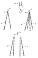
- every crane needs to be equipped with four different and separate lifting sling units containing one, two, three and four legs, respectively, as illustrated in figure 1a .
- a proper and secure lifting can be achieved for different kinds of loads.
- Table 2A illustrates the rating for a special use, where all legs carry an equal load, and the legs have an angle of 45° to the vertical: Table 2A - special use Chain size (mm) WLL (t) 1-leg WLL (t) 2-leg*) WLL (t) 3-leg*) WLL (t) 4-leg*)**) 6 1.5 2.1 3.1 4.2 8 2.5 3.5 5.2 7.0 10 4.0 5.6 8.4 11.2 13 6.5 9.1 13.6 18.2 16 10 14 21 28 20 16 22 33 44 *) WLL for 2-, 3- and 4-leg are given for leg angle of 45° to vertical. **) WLL for four legs apply based on that special measures are taken that each leg is carrying equal share of the load. Otherwise WLL for three legs will apply.
- leg angle to the vertical can be selected to any reasonable value, but in this particular example, the WLL is based on an angle of 45°.
- Table 2B below, there is shown the rating for general use, where all legs should carry an equal load for sling units with two and three legs, respectively: Table 2B - general use Chain size (mm) WLL (t) 1-leg WLL (t) 2-leg, 45° WLL (t) 2-leg 60° WLL (t) 3+4-leg 45° WLL (t) 3+4-leg 60° 6 1.5 2.1 1.5 3.1 2.2 8 2.5 3.5 2.5 5.2 3.7 10 4.0 5.6 4.0 8.4 6.0 13 6.5 9.1 6.5 13.6 9.7 16 10 14 10 21 15 20 16 22 16 33 24
- WLL is indicated for two angles to the vertical, viz. 45° and 60°, respectively.
- the WLL can be rated based on the leg angle to the horizontal (rather than the vertical).
- GB 2138919 describes a chain connecting means comprising a master link and an intermediate member having means to enable one or more link chains to be connected thereto.
- the intermediate member and the link chains are no pre-assembled parts.
- the lifting sling units for big size chains with units having three or four legs are very heavy to handle manually, especially when attaching such a sling unit to a lifting hook.
- Table III indicates the typical weight, for different chain sizes, of a lifting sling unit including a master link, joining members and the various chain legs, each having a length of about 1.5 m. These weights have to be lifted manually at the lifting site.
- Table 3 - weight of lifting sling units with four legs Chain size (mm) Weight (kg) 13 mm 40 kg 16 mm 60 kg 20 mm 93 kg
- a primary object of the present invention is to increase the operational safety of the lifting sling system.
- Another object is to reduce the number of parts included in the system, thereby reducing costs and increasing the overall efficiency.
- the above stated objects are met for a lifting sling system having the features stated in claim 1.
- the various lifting sling units are adapted for selective coupling a particular load to the lifting hook in accordance with information provided on an information carrier, such as a sling tag, being permanently attached to the head-link of the lifting sling system and having clear markings showing the various possible combinations of the lifting sling units, and the associated working load limits to be observed for each such combination.
- the lifting sling system also includes at least one further information carrier as a free component containing the same information as the one which is permanently attached to a member forming a part of the lifting sling system.
- each lifting sling unit will be relatively light in weight and easy to handle.
- the head link assembly includes one or two sublinks, e.g. having a flattened portion with reduced thickness so as to enable quick coupling thereof, at the lifting site, to a coupling member of an associated lifting sling unit.
- An important aspect of the present invention is to provide an information carrier, such as a lifting sling tag, providing information addressed to any user of the system at a lifting site, concerning permitted work load limits to be observed for a small number of combinable lifting sling units.
- an information carrier such as a lifting sling tag
- FIG 2 there is shown a first embodiment of the lifting sling system according to the invention.
- the system includes a relatively small number of combinable lifting sling units, namely two dual lifting sling units 20 and one single lifting sling unit 10.
- the single lifting sling unit 10 consists of three pre-assembled, inseparable members being permanently connected to each other, viz. a single coupling member in the form of a hook 11 which is quick-connectable to a lifting hook 1 via a closed head-link 30, a single sling leg portion 12 connected to the coupling hook 11, and a connector in the form of a hook 13 at the end of the single sling leg portion 12 for connection to a load at a lifting site.
- each dual lifting sling unit 20 consists of five pre-assembled, inseparable members being permanently connected to each other, viz. a dual coupling member in the form of a hook 21, which is quick-connectable to the lifting hook 1 via the closed head-link 30, a pair of sling leg portions 22 connected to the dual coupling hook 21, and two connectors in the form of hooks 23 at the end of each sling leg portion for connection to the load at the lifting site.
- the quick-connectable hooks 11, 21 and the head-link 30 are of the kind disclosed generally in EP 868386 B1 .
- the head-link 30 has a flattened portion 31 with reduced thickness
- the hook 11 and 21, respectively has a hook portion with a limited hook opening 11A and 21A, respectively, fitting snugly onto the flattened portion of the head-link.
- the hook opening 11a, 21a is smaller than the material thickness of the head-link 30 but larger than the reduced thickness at said flattened portion 31.
- one or two of these lifting sling units 10, 20 are coupled to the head-link 30, which in turn can be hung onto the lifting hook 1.
- this lifting sling system consisting of the head-link 30, the single lifting sling unit 10 and the two dual lifting sling units 20, it is possible to select a suitable combination of lifting sling units so as to obtain a required number of sling leg portions to be coupled to a load, namely one single sling leg portion, using the lifting sling unit 10, two sling leg portions, using one of the dual lifting sling units 20, three sling leg portions, using the single lifting sling unit 10 and one of the dual lifting sling units 20, or four sling leg portions, using the two dual lifting sling units 20.
- An information carrier in the form of a sling tag 32 is permanently attached to the head-link 30.
- the sling tag has clear markings showing the various possible combinations of the lifting sling units, and the associated working load limits to be observed for each such combination. As appears at the upper left part of figure 2 , these combinations are clearly visible to the user. In this case, it is assumed that the sling leg portion angle to the vertical is no more than 45°. Also, it is assumed that all sling leg portions are uniformly loaded even in the case of four sling leg portions being used.
- the working load limit values correspond to those shown in table 2A above for the chain size 10 mm.
- the lifting sling system includes only a small number of lifting sling units so as to keep down the amount of hardware.
- Another essential feature is that there should be no heavy lifting sling units. So the maximum number of sling leg portions in a lifting sling unit is two, and there is no lifting sling unit with more than two sling leg portions.
- At least one of the lifting sling units may be provided with a shortening device, e.g. in the form of a coupling hook 21S having such a function integrated in its structure or as a separate component (not shown).
- a shortening device e.g. in the form of a coupling hook 21S having such a function integrated in its structure or as a separate component (not shown).
- figure 3 there is illustrated an even simpler embodiment with only two lifting sling units (shown at the lower portion of figure 3 ), namely one single lifting sling unit 10 and one dual lifting sling unit 20 as well as a closed head-link or master-link 30 with a sling tag 32.
- the latter is shown in larger scale to the right in figure 3 .
- the lifting sling system consists of two dual lifting sling units 20, shown in the lower part of figure 4 .
- the sling unit or combination thereof can be hooked onto the lifting hook 1 with the closed head-link 30.
- the sling tag 32 is not shown in detail, but the information contains information for the two options, viz. with two legs and four legs, respectively.
- FIG 5 there is shown a lifting sling system having altogether five lifting sling units as shown at the lower part of figure 5 .
- There is one lifting sling unit 10 with a chain size n + 2 1, one dual lifting sling unit 20 with chain size n + 1, two dual lifting sling units 20' with chain size n and one single lifting sling unit 10', likewise with the chain size n.
- the safety is increased, since the user will have a clear indication of the permissible combinations on the sling tag being an integral part of the system, irrespective of the particular combination being used.
- each lifting sling unit 10, 20, 10' or 20' to be handled is much less than the prior art combinations involving three or four sling leg portions.
- each sub-link 35 may have a flattened portion 36 corresponding to the flattened portion 31 on the head-link 30 shown in figures 2 through 5 .
- each sub-link 35 should be quick-coupled to a coupling hook (or possibly two coupling hooks), e.g. of a kind shown in figure 2 .
- a dual coupling hook 21 is also shown in figure 7a , together with an associated head-link 30 or sub-link 35.
- An arrow A indicates the movement for coup-ling the hook 21 onto the head-link 30 or sub-link 35.
- FIG 7b there is shown a similar coupling hook 21' provided with a latch pin 25 which is held in a locking position, as shown, by means of a helical spring 26.
- the latch pin 25 can be opened by pulling the pin 25 manually at its head member 27 against the action of the spring 26.
- FIG. 7c Another hook 21'' with a slightly different latch member 28 is shown in figure 7c .
- the latch member 28 is pivotally journalled and is likewise held in a locking position by means of a spring member (not visible in figure 7c ).
- the quick coupling may thus be achieved by means of a flattened head-link or sub-link, or by way of coupling hook member having a gap accommodating the full cross-sectional diameter of a head-link or a sub-link but being provided with a locking member, e.g. of the kind shown in figures 7b and 7c .
- FIG 8 there is shown a sling tag containing more information, viz. the working load limits for leg angles up to 45° and angles in the interval 45-60°, respectively, for each permissible combination of lifting sling units. It is important that the user of a particular lifting sling system will always be able to obtain information from a sling tag or some corresponding information carrier concerning the work load limits of the permitted combinations of lifting sling units. Of course, different kinds of information carriers can be used, providing the necessary visual information or, alternatively, in some other way, e.g. audio.
- the lifting sling system may include one or more additional sling tags or information carriers which constitute freely movable components and containing substantially the same information as the information given on the information carriers being permanently attached to one or several members forming integral parts of the lifting sling system.
- the sling tag of figure 8 may constitute such an additional sling tag, e.g. a duplicate copy of a sling tag permanently attached to a head-link assembly or some other component.
- an operator of the lifting sling system may pick up the extra sling tag and compare it with the actual lifting sling combination being used at a lifting site.
- a special feature of the sling tag of fig. 8 is the upper part with two edge portions 32a and 32b standing at an angle to the longer side edges 32c, 32d, corresponding to the actual angle (45° and 60°) of one or more permissible combinations of lifting sling units. The operator can easily compare these angles with the respective actual sling leg portions at the lifting site.
- each sling leg portion of each sling unit may be used.
- the quick-coupling members may be constituted by other members than hooks.
- the terminal ends of each sling leg portion may be attached to other kinds of connectors or coupling members for secure attachment to a particular load.
- the connector at the lower end of the sling leg portion may be constituted by a quick-connectable coupling member 13', e.g. similar to the upper coupling member 11'.
- the lower connector 13 can be swiftly connected to a particular end component, selected by the operator at the lifting site, such as an end link 14a, a plate clamp 14b, a sling hook 14c, a self-locking safety hook 14d, a swivel hook 14e or some other component adapted to the particular load.
- the coupling portion of the end component may have a flattened portion (14a, 14d, 14e) or a uniform cross-section (14b, 14c).
- the total number of lifting sling units and associated components is kept to a minimum.
Description
- The invention relates to a lifting sling system according to the preamble of
claim 1. Such a lifting sling system is disclosed byGB 2138919 - A currently used lifting sling system of this kind is illustrated in
figure 1a . Each lifting sling unit, having pre-assembled inseparable parts, comprises a head link or master link, a coupling member for each sling leg portion, a number of interconnected chain links for each leg, these legs having normally the same length, and a sling hook or some other fitting as a lower terminal or connector for each sling leg portion. The assembly of each lifting sling unit is made by an authorized person with the required competence in an assembly workshop ("sling shop") where special assembly tools are used for making the sling as an integral unit with inseparable parts. These parts are not supposed to be taken apart in operation at a lifting site, except for possible inspection by an authorized person. - The lifting capacity of each sling unit, normally called the Working Load Limit (WLL), is based on the chain dimension, the number of legs which are all assumed to carry an equal part of the load and the angle of each leg to the vertical, and is indicated on a metal sling tag, which is permanently attached to the master link or elsewhere at the top of each lifting sling unit. In general, when there are different loads to be handled, e.g. with mobile cranes, every crane needs to be equipped with four different and separate lifting sling units containing one, two, three and four legs, respectively, as illustrated in
figure 1a . Hereby, a proper and secure lifting can be achieved for different kinds of loads. - For multi-leg lifting sling units, there are different methods of rating and presenting the working load limit (WLL). Table 2A (below) illustrates the rating for a special use, where all legs carry an equal load, and the legs have an angle of 45° to the vertical:
Table 2A - special use Chain size (mm) WLL (t) 1-leg WLL (t) 2-leg*) WLL (t) 3-leg*) WLL (t) 4-leg*)**) 6 1.5 2.1 3.1 4.2 8 2.5 3.5 5.2 7.0 10 4.0 5.6 8.4 11.2 13 6.5 9.1 13.6 18.2 16 10 14 21 28 20 16 22 33 44 *) WLL for 2-, 3- and 4-leg are given for leg angle of 45° to vertical.
**) WLL for four legs apply based on that special measures are taken that each leg is carrying equal share of the load. Otherwise WLL for three legs will apply. - Thus, all legs should carry an equal load, also for four-leg sling units. Special measures are required to make sure that the legs in a four-leg sling do in fact carry an equal load. The leg angle to the vertical can be selected to any reasonable value, but in this particular example, the WLL is based on an angle of 45°.
- In table 2B, below, there is shown the rating for general use, where all legs should carry an equal load for sling units with two and three legs, respectively:
Table 2B - general use Chain size (mm) WLL (t) 1-leg WLL (t) 2-leg, 45° WLL (t) 2-leg 60° WLL (t) 3+4-leg 45° WLL (t) 3+4-leg 60° 6 1.5 2.1 1.5 3.1 2.2 8 2.5 3.5 2.5 5.2 3.7 10 4.0 5.6 4.0 8.4 6.0 13 6.5 9.1 6.5 13.6 9.7 16 10 14 10 21 15 20 16 22 16 33 24 - On the other hand, for four-leg sling units, only three legs are considered to carry the load, because no special measures are taken for equal distribution of the load. Also, in this example, WLL is indicated for two angles to the vertical, viz. 45° and 60°, respectively.
- As an alternative (not shown), the WLL can be rated based on the leg angle to the horizontal (rather than the vertical).
GB 2138919 - Long term experience from lifting sling systems of the kind described above have shown some safety risks as well as inefficiencies in respect of practical operation and costs.
- The lifting sling units for big size chains with units having three or four legs are very heavy to handle manually, especially when attaching such a sling unit to a lifting hook.
- Table III, below, indicates the typical weight, for different chain sizes, of a lifting sling unit including a master link, joining members and the various chain legs, each having a length of about 1.5 m. These weights have to be lifted manually at the lifting site.
Table 3 - weight of lifting sling units with four legs Chain size (mm) Weight (kg) 13 mm 40 kg 16 mm 60 kg 20 mm 93 kg - Such heavy weights will of course involve a safety risk for those who manually handle the lifting sling units.
- Moreover, it frequently happens that a particular lifting sling unit, intended for use with all sling leg portions being active, is fitted to the load with only a few sling leg portions. Then, the partial load taken up by each active sling leg portion, will be substantially higher than the intended one, and also being indicated on the associated sling tag. In such a case, the actual load on each sling leg portion is higher. Consequently there will be a risk of overloading even if the operator observes the working load limits indicated on the sling tag. As an example, in table 2A above, the working load limit for a three leg chain sling unit of
chain size 10 mm is 8.4 tons. However, in case only two legs are used for lifting and one sling leg portion is idle, the actual maximum load should be 5.6 tons, a value which does not appear on the sling tag being used in the,prior art systems. Clearly, this involves a clear risk of overload. - Another risk involved in using multileg lifting sling units, where some of the sling leg portions are hanging idle during the lifting operation, the remaining sling leg portions will be allowed to swing around in the air without control, thereby possibly hitting people in their heads or being inadvertently caught by other objects or edges. Of course, this will bring about a serious risk for accidents and personal injuries during the lifting operation.
- As a matter of economy and efficiency, it is desirable to keep down the weight of the lifting sling equipment, especially for mobile cranes and cranes mounted on lorries and the like, thereby saving fuel and increasing the active transportation capacity. From this point of view, there is a need for higher flexibility and a minimum amount of equipment. In the prior art example illustrated in
figure 1 , there are four different lifting sling units having one, two, three and four sling leg portions, respectively, depending on the type of load to be lifted. All in all, this adds up to 1+2+3+4 = 10 sling leg portions and four master links, one for each lifting sling unit, as appears fromfigure 1a . - Moreover, it is of course possible to combine a number of lifting sling units each having only one or two sling leg portions. However, the sling tags will not indicate the correct working load limit, but a smaller one (5.6 tons instead of 8.4 tons) which is clearly inefficient and misleading.
- With this background, a primary object of the present invention is to increase the operational safety of the lifting sling system.
- Another object is to reduce the number of parts included in the system, thereby reducing costs and increasing the overall efficiency.
- According to the present invention, the above stated objects are met for a lifting sling system having the features stated in
claim 1. The various lifting sling units are adapted for selective coupling a particular load to the lifting hook in accordance with information provided on an information carrier, such as a sling tag, being permanently attached to the head-link of the lifting sling system and having clear markings showing the various possible combinations of the lifting sling units, and the associated working load limits to be observed for each such combination. Possibly, the lifting sling system also includes at least one further information carrier as a free component containing the same information as the one which is permanently attached to a member forming a part of the lifting sling system. - In this way, the number of different lifting sling units will be kept to a minimum, and each lifting sling unit will be relatively light in weight and easy to handle.
- Possibly, the head link assembly includes one or two sublinks, e.g. having a flattened portion with reduced thickness so as to enable quick coupling thereof, at the lifting site, to a coupling member of an associated lifting sling unit.
- An important aspect of the present invention is to provide an information carrier, such as a lifting sling tag, providing information addressed to any user of the system at a lifting site, concerning permitted work load limits to be observed for a small number of combinable lifting sling units. Hereby, it will be ensured that the indicated working load limits will not be exceeded in practice, and also that the capacity of the lifting sling units can be used in an optimal way.
- Further advantages and features of the invention will be apparent from the detailed description below, reference being made to the accompanying drawings.
-
-
Figure 1a illustrate schematically a prior art lifting sling system including lifting sling units with different numbers of sling leg portions in each unit; -
Figure 1b and 1c illustrate schematically a lifting sling system which is not according to the present invention; -
Figures 2 and 2a illustrate schematically a first embodiment of a lifting sling system according to the present invention; -
Figure 3 illustrates, even more schematically, a second embodiment of a lifting sling system according to the present invention; -
Figure 4 illustrates, likewise very schematically, a third embodiment of a lifting sling system according to the present invention; -
Figure 5 illustrates, likewise very schematically, a fourth embodiment of lifting sling system according to the present invention; -
Figures 6a, 6b and 6c illustrate various head-link assemblies included in a lifting sling system according to the present invention; -
Figures 7a, 7b and 7c illustrate schematically three embodiments of a coupling member which is quick-connectable to a head link assembly; -
Figure 8 shows a sling tag to be used for lifting sling system with 10 mm chain links for general use, i.e. without any special measures being taken for equal distribution of the load when a total of four sling leg portions are being used; and -
Figure 9 shows a lifting sling unit having a connector at its lower end which is adapted for quick coupling to a selected end component. - In
figure 2 , there is shown a first embodiment of the lifting sling system according to the invention. The system includes a relatively small number of combinable lifting sling units, namely two duallifting sling units 20 and one singlelifting sling unit 10. The singlelifting sling unit 10 consists of three pre-assembled, inseparable members being permanently connected to each other, viz. a single coupling member in the form of ahook 11 which is quick-connectable to alifting hook 1 via a closed head-link 30, a singlesling leg portion 12 connected to thecoupling hook 11, and a connector in the form of ahook 13 at the end of the singlesling leg portion 12 for connection to a load at a lifting site. - Similarly, each dual
lifting sling unit 20 consists of five pre-assembled, inseparable members being permanently connected to each other, viz. a dual coupling member in the form of ahook 21, which is quick-connectable to thelifting hook 1 via the closed head-link 30, a pair ofsling leg portions 22 connected to thedual coupling hook 21, and two connectors in the form ofhooks 23 at the end of each sling leg portion for connection to the load at the lifting site. - The quick-
connectable hooks link 30 are of the kind disclosed generally inEP 868386 B1 link 30 has a flattenedportion 31 with reduced thickness, and thehook hook opening link 30 but larger than the reduced thickness at said flattenedportion 31. - In use, at a lifting site, one or two of these lifting
sling units link 30, which in turn can be hung onto thelifting hook 1. Thus, with this lifting sling system consisting of the head-link 30, the singlelifting sling unit 10 and the two duallifting sling units 20, it is possible to select a suitable combination of lifting sling units so as to obtain a required number of sling leg portions to be coupled to a load, namely one single sling leg portion, using the liftingsling unit 10, two sling leg portions, using one of the duallifting sling units 20, three sling leg portions, using the singlelifting sling unit 10 and one of the duallifting sling units 20, or four sling leg portions, using the two duallifting sling units 20. - An information carrier in the form of a
sling tag 32 is permanently attached to the head-link 30. The sling tag has clear markings showing the various possible combinations of the lifting sling units, and the associated working load limits to be observed for each such combination. As appears at the upper left part offigure 2 , these combinations are clearly visible to the user. In this case, it is assumed that the sling leg portion angle to the vertical is no more than 45°. Also, it is assumed that all sling leg portions are uniformly loaded even in the case of four sling leg portions being used. The working load limit values correspond to those shown in table 2A above for thechain size 10 mm. - According to the invention, it is essential that the lifting sling system includes only a small number of lifting sling units so as to keep down the amount of hardware. Another essential feature is that there should be no heavy lifting sling units. So the maximum number of sling leg portions in a lifting sling unit is two, and there is no lifting sling unit with more than two sling leg portions.
- As illustrated in
figure 2a , at least one of the lifting sling units may be provided with a shortening device, e.g. in the form of a coupling hook 21S having such a function integrated in its structure or as a separate component (not shown). - In
figure 3 , there is illustrated an even simpler embodiment with only two lifting sling units (shown at the lower portion offigure 3 ), namely one singlelifting sling unit 10 and one duallifting sling unit 20 as well as a closed head-link or master-link 30 with asling tag 32. The latter is shown in larger scale to the right infigure 3 . - With this embodiment, it is possible to use only the single
lifting sling unit 10, only the duallifting sling unit 20 or a combination of these liftingsling units figure 3 . - Another embodiment with only two lifting sling units is shown in
figure 4 . Here, the lifting sling system consists of two duallifting sling units 20, shown in the lower part offigure 4 . Here, it is possible to use only one duallifting sling unit 20, as shown at the upper left infigure 4 , or a combination of the two liftingsling units 20, as shown at the upper right infigure 4 . In either case, the sling unit or combination thereof can be hooked onto thelifting hook 1 with the closed head-link 30. In this case, thesling tag 32 is not shown in detail, but the information contains information for the two options, viz. with two legs and four legs, respectively. - In
figure 5 , there is shown a lifting sling system having altogether five lifting sling units as shown at the lower part offigure 5 . In this case, the various lifting sling units have different chain sizes, including a largest size (n + 2), a next smaller size (n + 1) and a smallest size (n), e.g. with n + 2 = 13 mm, n + 1 = 10 mm and n = 8 mm. There is onelifting sling unit 10 with a chainsize n + 2, one duallifting sling unit 20 with chainsize n + 1, two duallifting sling units 20' with chain size n and one single lifting sling unit 10', likewise with the chain size n. - With such differentiation of the chain size among the lifting sling units, it is possible to carry approximately the same total load with one, two, three or four sling leg portions, as clearly indicated on the sling tag 32' to the right in
figure 5 . The four combinations indicated on the sling tag 32' are shown in the upper part offigure 5 . Of course, the selection of a particular combination depends on the size and shape of the load (not shown). - With a lifting sling system as illustrated in
figure 5 , it is thus possible to make more efficient use of the capacity of the crane even for a reduced number of legs, for combinations with one and two sling leg portions. Compare table 2A above. - It will be apparent that the total number of sling leg portions, and the total weight of the lifting sling system according to the invention, is substantially reduced in comparison to the prior art systems (compare
figure 1a ). For example, in the system shown infigure 2 , there are only five sling leg portions altogether, whereas in the prior art system shown infigure 1a , there are in total ten such sling leg portions. - Still, the safety is increased, since the user will have a clear indication of the permissible combinations on the sling tag being an integral part of the system, irrespective of the particular combination being used.
- Furthermore, of course, the weight of each lifting
sling unit - Alternatively, it may be advantageous to use a head-link assembly having one (
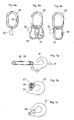
figure 6c ) or two (figure 6b ) sub-links 35 permanently coupled thereto, rather than the single head-link or master-link as shown infigure 6a . When usingsuch sub-links 35, the main head-link 30 is preferably uniform in thickness, whereas each sub-link 35 may have a flattenedportion 36 corresponding to the flattenedportion 31 on the head-link 30 shown infigures 2 through 5 . When using twosub-links 35, as shown infigure 6b , each sub-link 35 should be quick-coupled to a coupling hook (or possibly two coupling hooks), e.g. of a kind shown infigure 2 . Adual coupling hook 21 is also shown infigure 7a , together with an associated head-link 30 orsub-link 35. An arrow A indicates the movement for coup-ling thehook 21 onto the head-link 30 orsub-link 35. - In
figure 7b , there is shown a similar coupling hook 21' provided with alatch pin 25 which is held in a locking position, as shown, by means of ahelical spring 26. Thelatch pin 25 can be opened by pulling thepin 25 manually at itshead member 27 against the action of thespring 26. - Another hook 21'' with a slightly
different latch member 28 is shown infigure 7c . Thelatch member 28 is pivotally journalled and is likewise held in a locking position by means of a spring member (not visible infigure 7c ). - The quick coupling may thus be achieved by means of a flattened head-link or sub-link, or by way of coupling hook member having a gap accommodating the full cross-sectional diameter of a head-link or a sub-link but being provided with a locking member, e.g. of the kind shown in
figures 7b and 7c . - In
figure 8 there is shown a sling tag containing more information, viz. the working load limits for leg angles up to 45° and angles in the interval 45-60°, respectively, for each permissible combination of lifting sling units. It is important that the user of a particular lifting sling system will always be able to obtain information from a sling tag or some corresponding information carrier concerning the work load limits of the permitted combinations of lifting sling units. Of course, different kinds of information carriers can be used, providing the necessary visual information or, alternatively, in some other way, e.g. audio. - The lifting sling system may include one or more additional sling tags or information carriers which constitute freely movable components and containing substantially the same information as the information given on the information carriers being permanently attached to one or several members forming integral parts of the lifting sling system.
- The sling tag of
figure 8 may constitute such an additional sling tag, e.g. a duplicate copy of a sling tag permanently attached to a head-link assembly or some other component. When being used as a free component, an operator of the lifting sling system may pick up the extra sling tag and compare it with the actual lifting sling combination being used at a lifting site. A special feature of the sling tag offig. 8 is the upper part with twoedge portions - It is also important that the various parts of a particular lifting sling system are identified or marked so as to indicate that each unit belongs to a certain lifting sling system. Such marking can be made by colour coding with the same colour to be applied e.g. on top of each lifting sling unit and on the head-link assembly. Alternative, special tags or sleeves may be attached on or around each unit. Such tags or sleeves may alternatively be provided with numbers or letter codes indicating the particular lifting sling system.
- Instead of chains, it would be possible to use wire ropes or fibre slings, such as fibre round slings or fibre webbing belts, for the sling leg portions of each sling unit. Of course, the quick-coupling members may be constituted by other members than hooks. Also, the terminal ends of each sling leg portion may be attached to other kinds of connectors or coupling members for secure attachment to a particular load.
- Finally, as illustrated in
figure 9 , the connector at the lower end of the sling leg portion may be constituted by a quick-connectable coupling member 13', e.g. similar to the upper coupling member 11'. In this way thelower connector 13 can be swiftly connected to a particular end component, selected by the operator at the lifting site, such as anend link 14a, aplate clamp 14b, asling hook 14c, a self-lockingsafety hook 14d, aswivel hook 14e or some other component adapted to the particular load. The coupling portion of the end component may have a flattened portion (14a, 14d, 14e) or a uniform cross-section (14b, 14c). - Accordingly, as compared to prior art systems, the total number of lifting sling units and associated components is kept to a minimum.
Claims (15)
- A lifting sling system for connecting various loads to a lifting hook (1), comprising a set of lifting sling units (10, 20) each consisting of a number of pre-assembled parts including a coupling member (11, 21), one or more sling leg portions (12, 22) and a connector (13, 23) at the end of each sling leg portion, said lifting sling system permitting selective coupling of at least one of said lifting sling units, at a lifting site, to said lifting hook, whereinsaid set of lifting sling units comprises only a small number of combinable lifting sling units, namely at least two and no more than totally five combinable lifting sling units, including- no heavy lifting sling units,- at least one and no more than three dual lifting sling units (20) each consisting of five pre-assembled members being permanently connected to each other, namely:- a dual coupling member (21) which is quick-connectable to said lifting hook (1) at said lifting site,- a pair of sling leg portions (22) connected to said dual coupling member, and- two connectors (23), one at the end of each sling leg portion for connection to said load at said lifting site, and- possibly no more than two single lifting sling units (10) consisting of three pre-assembled members being permanently connected to each other, namely:- a single coupling member (11) which is quick-connectable to said lifting hook (1) at said lifting site,- a single sling leg portion (12) connected to said single coupling member, and- a connector (13) at the end of said single sling leg portion (12) for connection to said load at said lifting site, there being no lifting sling unit in the system having more than two sling leg portions, the lifting sling system also comprising- a head link assembly having a closed head link (30) dimensioned to be hung onto said lifting hook and adapted for quick-coupling to at least one and no more than two of said lifting sling units,characterised in that the lifting sling system comprises- an information carrier (32) being permanently attached to the head link and having clear markings showing the various possible combinations of the lifting sling units, and the associated working load limits to be observed for each such combination,there being at least one permissible combination of lifting sling units having a total,of two sling leg portions but no permissible combination of lifting sling units having more than a total of four sling leg portions, said combinable lifting sling units being adapted for selective coupling of a particular load to said lifting hook in accordance with the information provided on the information carrier (32).
- A lifting sling system as defined in claim 1, wherein said closed head link (30) has a flattened portion (31) with reduced thickness so as to enable quick-coupling thereof, at said lifting site, to at least one and no more than two of said coupling members (11, 21) of said single and dual lifting sling units (10, 20).
- A lifting sling system as defined in claim 1, wherein said head link assembly includes at least one and no more than two sub-links (35), so as to enable quick-coupling thereof, at said lifting site, to at least one of said coupling members (11, 21) of said single and dual lifting sling units.
- A lifting sling system as defined in claim 2 or 3, wherein each of said coupling members (11, 21) is provided with a hook portion having a limited hook opening (11a, 21a) which is smaller than the material thickness of said head link (30) or sub-link (35) but larger than a reduced thickness at a flattened portion (31, 36).
- A lifting sling system as defined in any one of claims 1-4, wherein all of said single and dual lifting sling units (10, 20) include leg portions consisting of chain links all having the same size.
- A lifting sling system as defined in claim 5, wherein said set of lifting sling units consists of one single lifting sling unit (10) and one dual lifting sling unit (20).
- A lifting sling system as defined in claim 5, wherein said set of lifting sling units consists of one single lifting sling unit (10) and two dual lifting sling units (20).
- A lifting sling system, as defined in claim 5, wherein said set of lifting sling units consists of two dual lifting sling units (20).
- A lifting sling system as defined in any one of claims 1-4, wherein said set of lifting sling units consists of lifting sling units (10, 20, 10', 20') each having chain links of the same size within the same lifting sling unit, the size of the chain links being different between at least two lifting sling units (10, 10'; 20, 20').
- A lifting sling system as defined in claim 9, wherein there are altogether three different sizes of chain links in the lifting sling system, including a first lifting sling unit (10) having chain links of a largest size, a second lifting sling unit (20) having chain links of a next smaller size, and at least two further lifting sling units (10', 20') having chain links of a smallest size, which lifting sling units are to be used in combinations having altogether at least three and no more than four sling leg portions.
- A lifting system as defined in claim 10, wherein said set of lifting sling units consists of five lifting sling units, namely:- a first, single lifting sling unit (10) with chain links of said largest size,- a second, dual lifting sling unit (20) with chain links of said next smaller size, and- three further lifting sling units with said smallest size, namely- one single lifting sling unit (10'), and- two dual lifting sling units (20').
- A lifting sling system as defined in any one claims 1-5, wherein said lifting sling units include sling leg portions each consisting of one of the following: a wire rope, a fibre round sling and a fibre webbing belt.
- A lifting sling system as defined in any one of the preceding claims, including at least one shortening device (21 S) for shortening at least one of said sling leg portions at said lifting site.
- A lifting sling system as defined in any one of the preceding claims, wherein said connector (13) at the lower end of at least one sling leg portion is constituted by a quick-connectable coupling member, adapted to be connected to a selectable end component.
- A lifting sling system as defined in claim 1, comprising at least one further information carrier (32) being separate from other components of the lifting sling system and containing the same information as said information carrier being permanently attached to said lifting sling system.
Applications Claiming Priority (1)
| Application Number | Priority Date | Filing Date | Title |
|---|---|---|---|
| PCT/SE2005/001480 WO2007040430A1 (en) | 2005-10-06 | 2005-10-06 | Lifting sling system |
Publications (3)
| Publication Number | Publication Date |
|---|---|
| EP1931589A1 EP1931589A1 (en) | 2008-06-18 |
| EP1931589A4 EP1931589A4 (en) | 2011-11-30 |
| EP1931589B1 true EP1931589B1 (en) | 2015-03-04 |
Family
ID=37906396
Family Applications (1)
| Application Number | Title | Priority Date | Filing Date |
|---|---|---|---|
| EP05791705.6A Active EP1931589B1 (en) | 2005-10-06 | 2005-10-06 | Lifting sling system |
Country Status (5)
| Country | Link |
|---|---|
| US (1) | US8157304B2 (en) |
| EP (1) | EP1931589B1 (en) |
| JP (1) | JP5107927B2 (en) |
| CN (1) | CN101277893B (en) |
| WO (1) | WO2007040430A1 (en) |
Cited By (1)
| Publication number | Priority date | Publication date | Assignee | Title |
|---|---|---|---|---|
| US10920619B2 (en) | 2018-06-20 | 2021-02-16 | Safran Aircraft Engines | Annular casting and shrink-fitted part of an aircraft turbine engine |
Families Citing this family (7)
| Publication number | Priority date | Publication date | Assignee | Title |
|---|---|---|---|---|
| WO2008123803A1 (en) * | 2007-04-04 | 2008-10-16 | Frenolink Förvaltnings AB | Lifting sling system |
| US9126757B2 (en) * | 2013-03-15 | 2015-09-08 | Howard Dunham | Lifting device for rolled objects |
| US10259688B1 (en) * | 2013-11-13 | 2019-04-16 | Mumser, Inc. | V-sling with hook positioning adapter |
| US10641305B2 (en) * | 2017-03-28 | 2020-05-05 | Forum Us, Inc. | Link extension connector |
| EP3392525B1 (en) | 2017-04-21 | 2022-03-09 | Pewag Austria GmbH | Hanging ring for multi-strand hangers |
| US20220073327A1 (en) * | 2020-09-08 | 2022-03-10 | Lift-All Company, Inc. | Hoist attachment for a forklift truck |
| EP4046953A1 (en) | 2021-02-17 | 2022-08-24 | Jörg Sembritzky | Modular system for suspension on a crane hook or a stop or a lashing point, as well as coupling hook for use in such a system |
Family Cites Families (20)
| Publication number | Priority date | Publication date | Assignee | Title |
|---|---|---|---|---|
| US4094141A (en) * | 1974-03-12 | 1978-06-13 | August Thiele | Terminal chain link with built-in indicator |
| DE2732246A1 (en) * | 1977-07-16 | 1979-02-01 | Thiele Fa August | HANGING HEAD FOR LOAD STRAND-ORIENTED SINGLE CHAIN SYSTEMS |
| US4139956A (en) * | 1977-08-11 | 1979-02-20 | C. C. Sharrow Company, Inc. | Sling identification means |
| JPS5927567Y2 (en) * | 1980-09-16 | 1984-08-09 | 東光資材株式会社 | bonded ring |
| NO149074C (en) * | 1980-11-10 | 1984-02-08 | Malmen Olle | PROCEDURE FOR ASSEMBLY OF PIPES FOR A PIPE PIPE, AND TOOL FOR THE PROCEDURE |
| IN160662B (en) * | 1982-04-15 | 1987-07-25 | Parsons Controls Ltd | |
| EP0105022B1 (en) * | 1982-09-21 | 1989-01-11 | RUD-Kettenfabrik Rieger & Dietz GmbH u. Co. | Connecting assembly for load-lifting devices |
| GB2138919B (en) * | 1983-04-30 | 1986-03-05 | Wheway Watson Holdings | Chain connecting means |
| JPH037178U (en) | 1989-06-10 | 1991-01-23 | ||
| FR2658803B1 (en) * | 1990-02-27 | 1992-04-24 | Sysma Sarl | HANDLING HOOK. |
| US5193480A (en) * | 1991-01-22 | 1993-03-16 | The Crosby Group, Inc. | Hoisting line fittings with working load limit indicia |
| US5103755A (en) | 1991-01-22 | 1992-04-14 | The Crosby Group, Inc. | Hoisting line fittings with working load limit indicia |
| CN1063456A (en) * | 1992-01-23 | 1992-08-12 | 刘新政 | Button type alarm for tyres |
| CN2177700Y (en) * | 1993-09-11 | 1994-09-21 | 洪川祥 | Metallic chain base |
| DE9407926U1 (en) * | 1994-05-11 | 1994-07-14 | Rud Ketten Rieger & Dietz | Load suspension or preparation device |
| SE506562C2 (en) * | 1995-12-22 | 1998-01-12 | Frenolink Foervaltnings Ab | Coupling device for coupling a lifting member with a flexible lifting strap |
| SE505973C2 (en) * | 1995-12-22 | 1997-10-27 | Frenolink Foervaltnings Ab | Coupling assembly |
| SE505974C2 (en) * | 1995-12-22 | 1997-10-27 | Frenolink Foervaltnings Ab | Multi-coupling for a chain |
| JPH1072182A (en) | 1996-08-30 | 1998-03-17 | Shinko Electric Co Ltd | Supporting device for hoist chain in hoist device |
| SE520807C2 (en) * | 2000-03-16 | 2003-08-26 | Frenolink Foervaltnings Ab | Method for safety measurement for lifting loops, lifting loop and safety label |
-
2005
- 2005-10-06 JP JP2008534478A patent/JP5107927B2/en active Active
- 2005-10-06 CN CN2005800517568A patent/CN101277893B/en active Active
- 2005-10-06 EP EP05791705.6A patent/EP1931589B1/en active Active
- 2005-10-06 WO PCT/SE2005/001480 patent/WO2007040430A1/en active Application Filing
- 2005-10-06 US US12/088,462 patent/US8157304B2/en active Active
Cited By (1)
| Publication number | Priority date | Publication date | Assignee | Title |
|---|---|---|---|---|
| US10920619B2 (en) | 2018-06-20 | 2021-02-16 | Safran Aircraft Engines | Annular casting and shrink-fitted part of an aircraft turbine engine |
Also Published As
| Publication number | Publication date |
|---|---|
| EP1931589A4 (en) | 2011-11-30 |
| CN101277893B (en) | 2011-04-20 |
| US8157304B2 (en) | 2012-04-17 |
| JP2009511381A (en) | 2009-03-19 |
| CN101277893A (en) | 2008-10-01 |
| US20080315604A1 (en) | 2008-12-25 |
| EP1931589A1 (en) | 2008-06-18 |
| JP5107927B2 (en) | 2012-12-26 |
| WO2007040430A1 (en) | 2007-04-12 |
Similar Documents
| Publication | Publication Date | Title |
|---|---|---|
| EP1931589B1 (en) | Lifting sling system | |
| EP0567471B1 (en) | Hoisting line fittings with working load limit indicia | |
| US6296288B1 (en) | Spreader bar apparatus | |
| CA2771526C (en) | Grommet shackle | |
| US8789248B2 (en) | Chain hook | |
| US5193480A (en) | Hoisting line fittings with working load limit indicia | |
| US7269937B2 (en) | Chain shortening device | |
| CN208648524U (en) | A kind of high intensity hoisting sling | |
| EP2137092B1 (en) | Lifting sling system | |
| US20210047149A1 (en) | Seesaw Hook Apparatus | |
| CN213085365U (en) | Forklift for transporting iron frame | |
| CN217201614U (en) | Balance beam combination lifting appliance | |
| CA2295420C (en) | Synthetic web fitting | |
| CN211419302U (en) | High-stability round eye sling | |
| CN210655815U (en) | Hoisting assembly and hoisting device | |
| CN109533615A (en) | The carrying conveying device of middle-size and small-size equipment installation | |
| CN220131684U (en) | Sling wire | |
| CN211393544U (en) | Novel round combined sling | |
| CN215974557U (en) | Steel bar hoisting device | |
| CN207468055U (en) | A kind of tool special for hoisting of diaphragm pump valve cone | |
| WO2022251926A1 (en) | A safety assembly securing a tipping tray in a raised position | |
| CN109160412A (en) | The open triangle boom hoisting of energy-saving prefabricated component single base and application method | |
| DE202009001168U1 (en) | Two-piece transport device for discs with center hole | |
| CN108100849A (en) | Vehicle frame hoisting mechanism with pulley | |
| DE102009006893A1 (en) | Transport device for transporting steel washers for vertical boring and turning lathe through e.g. fork-lift trucks, has load carrier provided with connecting element and locking slide, where two brackets are connected by connecting element |
Legal Events
| Date | Code | Title | Description |
|---|---|---|---|
| PUAI | Public reference made under article 153(3) epc to a published international application that has entered the european phase |
Free format text: ORIGINAL CODE: 0009012 |
|
| 17P | Request for examination filed |
Effective date: 20080328 |
|
| AK | Designated contracting states |
Kind code of ref document: A1 Designated state(s): AT BE BG CH CY CZ DE DK EE ES FI FR GB GR HU IE IS IT LI LT LU LV MC NL PL PT RO SE SI SK TR |
|
| A4 | Supplementary search report drawn up and despatched |
Effective date: 20111103 |
|
| RIC1 | Information provided on ipc code assigned before grant |
Ipc: B66C 1/12 20060101AFI20111027BHEP Ipc: B66C 15/00 20060101ALI20111027BHEP |
|
| DAX | Request for extension of the european patent (deleted) | ||
| 17Q | First examination report despatched |
Effective date: 20121109 |
|
| GRAP | Despatch of communication of intention to grant a patent |
Free format text: ORIGINAL CODE: EPIDOSNIGR1 |
|
| INTG | Intention to grant announced |
Effective date: 20141002 |
|
| GRAS | Grant fee paid |
Free format text: ORIGINAL CODE: EPIDOSNIGR3 |
|
| GRAA | (expected) grant |
Free format text: ORIGINAL CODE: 0009210 |
|
| AK | Designated contracting states |
Kind code of ref document: B1 Designated state(s): AT BE BG CH CY CZ DE DK EE ES FI FR GB GR HU IE IS IT LI LT LU LV MC NL PL PT RO SE SI SK TR |
|
| REG | Reference to a national code |
Ref country code: GB Ref legal event code: FG4D |
|
| REG | Reference to a national code |
Ref country code: CH Ref legal event code: EP |
|
| REG | Reference to a national code |
Ref country code: IE Ref legal event code: FG4D |
|
| REG | Reference to a national code |
Ref country code: AT Ref legal event code: REF Ref document number: 713679 Country of ref document: AT Kind code of ref document: T Effective date: 20150415 |
|
| REG | Reference to a national code |
Ref country code: DE Ref legal event code: R096 Ref document number: 602005045976 Country of ref document: DE Effective date: 20150416 |
|
| REG | Reference to a national code |
Ref country code: AT Ref legal event code: MK05 Ref document number: 713679 Country of ref document: AT Kind code of ref document: T Effective date: 20150304 Ref country code: NL Ref legal event code: VDEP Effective date: 20150304 |
|
| PG25 | Lapsed in a contracting state [announced via postgrant information from national office to epo] |
Ref country code: LT Free format text: LAPSE BECAUSE OF FAILURE TO SUBMIT A TRANSLATION OF THE DESCRIPTION OR TO PAY THE FEE WITHIN THE PRESCRIBED TIME-LIMIT Effective date: 20150304 Ref country code: SE Free format text: LAPSE BECAUSE OF FAILURE TO SUBMIT A TRANSLATION OF THE DESCRIPTION OR TO PAY THE FEE WITHIN THE PRESCRIBED TIME-LIMIT Effective date: 20150304 Ref country code: FI Free format text: LAPSE BECAUSE OF FAILURE TO SUBMIT A TRANSLATION OF THE DESCRIPTION OR TO PAY THE FEE WITHIN THE PRESCRIBED TIME-LIMIT Effective date: 20150304 Ref country code: ES Free format text: LAPSE BECAUSE OF FAILURE TO SUBMIT A TRANSLATION OF THE DESCRIPTION OR TO PAY THE FEE WITHIN THE PRESCRIBED TIME-LIMIT Effective date: 20150304 |
|
| REG | Reference to a national code |
Ref country code: LT Ref legal event code: MG4D |
|
| PG25 | Lapsed in a contracting state [announced via postgrant information from national office to epo] |
Ref country code: AT Free format text: LAPSE BECAUSE OF FAILURE TO SUBMIT A TRANSLATION OF THE DESCRIPTION OR TO PAY THE FEE WITHIN THE PRESCRIBED TIME-LIMIT Effective date: 20150304 Ref country code: GR Free format text: LAPSE BECAUSE OF FAILURE TO SUBMIT A TRANSLATION OF THE DESCRIPTION OR TO PAY THE FEE WITHIN THE PRESCRIBED TIME-LIMIT Effective date: 20150605 Ref country code: LV Free format text: LAPSE BECAUSE OF FAILURE TO SUBMIT A TRANSLATION OF THE DESCRIPTION OR TO PAY THE FEE WITHIN THE PRESCRIBED TIME-LIMIT Effective date: 20150304 |
|
| PG25 | Lapsed in a contracting state [announced via postgrant information from national office to epo] |
Ref country code: NL Free format text: LAPSE BECAUSE OF FAILURE TO SUBMIT A TRANSLATION OF THE DESCRIPTION OR TO PAY THE FEE WITHIN THE PRESCRIBED TIME-LIMIT Effective date: 20150304 |
|
| PG25 | Lapsed in a contracting state [announced via postgrant information from national office to epo] |
Ref country code: PT Free format text: LAPSE BECAUSE OF FAILURE TO SUBMIT A TRANSLATION OF THE DESCRIPTION OR TO PAY THE FEE WITHIN THE PRESCRIBED TIME-LIMIT Effective date: 20150706 Ref country code: CZ Free format text: LAPSE BECAUSE OF FAILURE TO SUBMIT A TRANSLATION OF THE DESCRIPTION OR TO PAY THE FEE WITHIN THE PRESCRIBED TIME-LIMIT Effective date: 20150304 Ref country code: SK Free format text: LAPSE BECAUSE OF FAILURE TO SUBMIT A TRANSLATION OF THE DESCRIPTION OR TO PAY THE FEE WITHIN THE PRESCRIBED TIME-LIMIT Effective date: 20150304 Ref country code: EE Free format text: LAPSE BECAUSE OF FAILURE TO SUBMIT A TRANSLATION OF THE DESCRIPTION OR TO PAY THE FEE WITHIN THE PRESCRIBED TIME-LIMIT Effective date: 20150304 Ref country code: RO Free format text: LAPSE BECAUSE OF FAILURE TO SUBMIT A TRANSLATION OF THE DESCRIPTION OR TO PAY THE FEE WITHIN THE PRESCRIBED TIME-LIMIT Effective date: 20150304 |
|
| REG | Reference to a national code |
Ref country code: FR Ref legal event code: PLFP Year of fee payment: 11 |
|
| PG25 | Lapsed in a contracting state [announced via postgrant information from national office to epo] |
Ref country code: IS Free format text: LAPSE BECAUSE OF FAILURE TO SUBMIT A TRANSLATION OF THE DESCRIPTION OR TO PAY THE FEE WITHIN THE PRESCRIBED TIME-LIMIT Effective date: 20150704 Ref country code: PL Free format text: LAPSE BECAUSE OF FAILURE TO SUBMIT A TRANSLATION OF THE DESCRIPTION OR TO PAY THE FEE WITHIN THE PRESCRIBED TIME-LIMIT Effective date: 20150304 |
|
| REG | Reference to a national code |
Ref country code: DE Ref legal event code: R097 Ref document number: 602005045976 Country of ref document: DE |
|
| PG25 | Lapsed in a contracting state [announced via postgrant information from national office to epo] |
Ref country code: IT Free format text: LAPSE BECAUSE OF FAILURE TO SUBMIT A TRANSLATION OF THE DESCRIPTION OR TO PAY THE FEE WITHIN THE PRESCRIBED TIME-LIMIT Effective date: 20150304 |
|
| PLBE | No opposition filed within time limit |
Free format text: ORIGINAL CODE: 0009261 |
|
| STAA | Information on the status of an ep patent application or granted ep patent |
Free format text: STATUS: NO OPPOSITION FILED WITHIN TIME LIMIT |
|
| PG25 | Lapsed in a contracting state [announced via postgrant information from national office to epo] |
Ref country code: DK Free format text: LAPSE BECAUSE OF FAILURE TO SUBMIT A TRANSLATION OF THE DESCRIPTION OR TO PAY THE FEE WITHIN THE PRESCRIBED TIME-LIMIT Effective date: 20150304 |
|
| 26N | No opposition filed |
Effective date: 20151207 |
|
| PG25 | Lapsed in a contracting state [announced via postgrant information from national office to epo] |
Ref country code: SI Free format text: LAPSE BECAUSE OF FAILURE TO SUBMIT A TRANSLATION OF THE DESCRIPTION OR TO PAY THE FEE WITHIN THE PRESCRIBED TIME-LIMIT Effective date: 20150304 |
|
| PG25 | Lapsed in a contracting state [announced via postgrant information from national office to epo] |
Ref country code: LU Free format text: LAPSE BECAUSE OF FAILURE TO SUBMIT A TRANSLATION OF THE DESCRIPTION OR TO PAY THE FEE WITHIN THE PRESCRIBED TIME-LIMIT Effective date: 20151006 |
|
| REG | Reference to a national code |
Ref country code: CH Ref legal event code: PL |
|
| PG25 | Lapsed in a contracting state [announced via postgrant information from national office to epo] |
Ref country code: MC Free format text: LAPSE BECAUSE OF FAILURE TO SUBMIT A TRANSLATION OF THE DESCRIPTION OR TO PAY THE FEE WITHIN THE PRESCRIBED TIME-LIMIT Effective date: 20150304 |
|
| REG | Reference to a national code |
Ref country code: IE Ref legal event code: MM4A |
|
| PG25 | Lapsed in a contracting state [announced via postgrant information from national office to epo] |
Ref country code: CH Free format text: LAPSE BECAUSE OF NON-PAYMENT OF DUE FEES Effective date: 20151031 Ref country code: LI Free format text: LAPSE BECAUSE OF NON-PAYMENT OF DUE FEES Effective date: 20151031 |
|
| PG25 | Lapsed in a contracting state [announced via postgrant information from national office to epo] |
Ref country code: BE Free format text: LAPSE BECAUSE OF FAILURE TO SUBMIT A TRANSLATION OF THE DESCRIPTION OR TO PAY THE FEE WITHIN THE PRESCRIBED TIME-LIMIT Effective date: 20150304 |
|
| REG | Reference to a national code |
Ref country code: FR Ref legal event code: PLFP Year of fee payment: 12 |
|
| PG25 | Lapsed in a contracting state [announced via postgrant information from national office to epo] |
Ref country code: IE Free format text: LAPSE BECAUSE OF NON-PAYMENT OF DUE FEES Effective date: 20151006 |
|
| PG25 | Lapsed in a contracting state [announced via postgrant information from national office to epo] |
Ref country code: BG Free format text: LAPSE BECAUSE OF FAILURE TO SUBMIT A TRANSLATION OF THE DESCRIPTION OR TO PAY THE FEE WITHIN THE PRESCRIBED TIME-LIMIT Effective date: 20150304 Ref country code: HU Free format text: LAPSE BECAUSE OF FAILURE TO SUBMIT A TRANSLATION OF THE DESCRIPTION OR TO PAY THE FEE WITHIN THE PRESCRIBED TIME-LIMIT; INVALID AB INITIO Effective date: 20051006 |
|
| PG25 | Lapsed in a contracting state [announced via postgrant information from national office to epo] |
Ref country code: CY Free format text: LAPSE BECAUSE OF FAILURE TO SUBMIT A TRANSLATION OF THE DESCRIPTION OR TO PAY THE FEE WITHIN THE PRESCRIBED TIME-LIMIT Effective date: 20150304 |
|
| PG25 | Lapsed in a contracting state [announced via postgrant information from national office to epo] |
Ref country code: TR Free format text: LAPSE BECAUSE OF FAILURE TO SUBMIT A TRANSLATION OF THE DESCRIPTION OR TO PAY THE FEE WITHIN THE PRESCRIBED TIME-LIMIT Effective date: 20150304 |
|
| REG | Reference to a national code |
Ref country code: FR Ref legal event code: PLFP Year of fee payment: 13 |
|
| REG | Reference to a national code |
Ref country code: FR Ref legal event code: PLFP Year of fee payment: 14 |
|
| P01 | Opt-out of the competence of the unified patent court (upc) registered |
Effective date: 20230403 |
|
| PGFP | Annual fee paid to national office [announced via postgrant information from national office to epo] |
Ref country code: GB Payment date: 20231004 Year of fee payment: 19 |
|
| PGFP | Annual fee paid to national office [announced via postgrant information from national office to epo] |
Ref country code: FR Payment date: 20231020 Year of fee payment: 19 Ref country code: DE Payment date: 20230929 Year of fee payment: 19 |