EP1931169A1 - Post filter for microphone array - Google Patents
Post filter for microphone array Download PDFInfo
- Publication number
- EP1931169A1 EP1931169A1 EP06797189A EP06797189A EP1931169A1 EP 1931169 A1 EP1931169 A1 EP 1931169A1 EP 06797189 A EP06797189 A EP 06797189A EP 06797189 A EP06797189 A EP 06797189A EP 1931169 A1 EP1931169 A1 EP 1931169A1
- Authority
- EP
- European Patent Office
- Prior art keywords
- filter
- noise
- post
- signal
- microphone array
- Prior art date
- Legal status (The legal status is an assumption and is not a legal conclusion. Google has not performed a legal analysis and makes no representation as to the accuracy of the status listed.)
- Withdrawn
Links
Images




Classifications
-
- G—PHYSICS
- G10—MUSICAL INSTRUMENTS; ACOUSTICS
- G10L—SPEECH ANALYSIS TECHNIQUES OR SPEECH SYNTHESIS; SPEECH RECOGNITION; SPEECH OR VOICE PROCESSING TECHNIQUES; SPEECH OR AUDIO CODING OR DECODING
- G10L21/00—Speech or voice signal processing techniques to produce another audible or non-audible signal, e.g. visual or tactile, in order to modify its quality or its intelligibility
- G10L21/02—Speech enhancement, e.g. noise reduction or echo cancellation
- G10L21/0208—Noise filtering
-
- G—PHYSICS
- G10—MUSICAL INSTRUMENTS; ACOUSTICS
- G10L—SPEECH ANALYSIS TECHNIQUES OR SPEECH SYNTHESIS; SPEECH RECOGNITION; SPEECH OR VOICE PROCESSING TECHNIQUES; SPEECH OR AUDIO CODING OR DECODING
- G10L21/00—Speech or voice signal processing techniques to produce another audible or non-audible signal, e.g. visual or tactile, in order to modify its quality or its intelligibility
- G10L21/02—Speech enhancement, e.g. noise reduction or echo cancellation
- G10L21/0208—Noise filtering
- G10L21/0216—Noise filtering characterised by the method used for estimating noise
- G10L2021/02161—Number of inputs available containing the signal or the noise to be suppressed
- G10L2021/02166—Microphone arrays; Beamforming
-
- H—ELECTRICITY
- H04—ELECTRIC COMMUNICATION TECHNIQUE
- H04R—LOUDSPEAKERS, MICROPHONES, GRAMOPHONE PICK-UPS OR LIKE ACOUSTIC ELECTROMECHANICAL TRANSDUCERS; ELECTRIC HEARING AIDS; PUBLIC ADDRESS SYSTEMS
- H04R3/00—Circuits for transducers
- H04R3/005—Circuits for transducers for combining the signals of two or more microphones
Definitions
- the present invention relates to a post-filter for a microphone array.
- the multi-channel Wiener filter generates an output with a signal-to-noise ratio higher than in the case where only the MVDR beam former is used.
- the addition of post-filtering is required to improve the performance of the microphone array.
- an mth observation signal x m (t) is formed of two components.
- a first signal is a desired one converted by an impulse response between a desired sound source and the mth sensor.
- X k ⁇ l S k ⁇ l ⁇ A k + N k ⁇ l
- k is a frequency index
- 1 is a frame index.
- X T k ⁇ l X 1 k ⁇ l , X 2 k ⁇ l , ... , X M k ⁇ l
- T k ⁇ l W H k ⁇ l ⁇ X k ⁇ l
- W(k,l) is a weight coefficient and the superscript H is a complex conjugate inversion.
- the multi-channel Wiener filter can be further decomposed into a MVDR beam former and a Wiener post-filter.
- Expression 1 W opt k ⁇ l ⁇ nn - 1 k ⁇ l ⁇ A k A H k ⁇ ⁇ nn - 1 k ⁇ l ⁇ A k ⁇ ⁇ ss - 1 k ⁇ l ⁇ ss - 1 k ⁇ l ⁇ nn - 1 k ⁇ l ⁇ nn - 1 k ⁇ l
- the first term represents the MVDR beam former
- the second term represents the Wiener post-filter.
- the MVDR beam former estimates the distortionless MMSE of the desired signal in a predetermined direction. By reducing the remaining noise further in the Wiener post-filter, the noise reduction capability can be improved to thereby generate a higher signal-to-noise ratio.
- MVDR beam former As the MVDR beam former, proposed are several adaptive algorithms such as a Frost beam former (Document 8: O. L. Frost, "An algorithm for linearly constrained adaptive array processing", in Proc. IEEE, vol. 60, pp. 926-935, 1972 ) and a generally-used side lobe canceler (GSC) and several non-adaptive algorithms such as a super-directive beam former on the assumption of a diffused noise field.
- a Frost beam former Document 8: O. L. Frost, "An algorithm for linearly constrained adaptive array processing", in Proc. IEEE, vol. 60, pp. 926-935, 1972
- GSC generally-used side lobe canceler
- non-adaptive algorithms such as a super-directive beam former on the assumption of a diffused noise field.
- a microphone array is arranged in advance in a desired signal direction within a range not departing from the general applicability and in order to process the same desired voice signal on each microphone, the multi-channel input is scaled.
- the Zelinski post-filter provides a solution of the Wiener filter in the noise field where noise instances are completely non-correlated, using the autocorrelation spectral density and cross-correlation spectral density estimated.
- the autocorrelation and cross-correlation spectral densities ⁇ x i x i (k,l) and ⁇ x i x j (k,l) can be simplified.
- the autocorrelation and cross-correlation spectral densities can be estimated by the microphone signal scaled.
- ⁇ x i x i (k, l), ⁇ x j x j (k, l) and ⁇ x i x j (k, l) can be simplified as follows.
- the McCowan post-filter presupposes the use of the multi-channel recording in an office, and is proposed to achieve an improved performance as compared with the Zelinski post-filter in this environment.
- the performance of the McCowan post-filter is expected to be reduced, however, in the presence of a difference between an estimated coherence function and the actual coherence function.
- An object of the present invention is to provide a novel post-filter having a hybrid structure in a diffused noise field.
- the diffused noise field like the environment in a reverberated room or vehicle compartments is proposed as a rational model of many practical noise environments.
- low-frequency noise instances are correlated high and high-frequency noise instances are correlated low.
- a multi-channel Wiener post-filter for high-frequency (correlated low) noise instances and a single-channel Wiener post-filter for low-frequency (correlated high) noise instances.
- a corrected Zelinski post-filter sufficiently considering and utilizing the correlation between the noise instances for different microphone pairs is employed.
- a single-channel Wiener post-filter for further reducing the "musical noise" due to a decision directivity signal-to-noise ratio estimation mechanism is employed.
- the post-filter according to this invention theoretically has a basic configuration of the multi-channel Wiener post-filter and can effectively reduce the high correlated noise instances and low correlated noise instances in the diffused noise field.
- the post-filter includes a microphone array having at least two microphones which are supplied with a voice signal, a beam former which forms the voice signal input from the microphone array, a divider which divides a target sound containing noise instances input from the microphone array into at least two frequency bands, a first filter which estimates a filter gain with the noise instances not correlated between the microphones, a second filter which estimates a filter gain of one microphone in the microphone array or a mean signal of the microphone array, an adder which adds the outputs of the first and second filters, and means for reducing the noise instances based on the outputs from the adder and the beam former.
- the diffused noise field which is one of the basic assumptions in this specification, is shown as a rational model for many actual noise environments.
- MSC k sin 2 ⁇ ⁇ kd / c 2 ⁇ ⁇ kd / c 2 where d is a distance between adjacent microphones and c is a sound velocity.
- An MSC function of a complete diffused noise field against frequency is shown in FIG. 1 . From FIG. 1 , several characteristics of the diffused noise field described below can be easily determined.
- the sound velocity c is regarded as a constant, and therefore, the transition frequency is determined simply by the distance d between the two microphones.
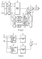
- FIG. 2 is a block diagram showing a post-filter according to the invention.
- FIG. 3 is a block diagram showing a general configuration of the corrected Zelinski post-filter.
- FIG. 4 is a block diagram showing a general configuration of the single-channel Wiener post-filter.
- the post-filter includes a microphone array 10 (hereinafter sometimes referred to simply as "microphone"), a fast Fourier transformer 11, a time matching unit 12, a beam former 13, a frequency band divider 14, a corrected Zelinski filter gain estimator 20 (corrected Zelinski post-filter), a single-channel filter gain estimator 30, an adder 40, a filter 41, a delay unit 42 and an inverse fast Fourier transformer 50.
- the corrected Zelinski filter gain estimator 20 includes a cross-correlation spectral density computing unit 21, an averaging unit 22, an autocorrelation spectral density computing unit 23, an averaging unit 24 and a divider 25.
- the single-channel filter gain estimator 30 includes an averaging unit 31, a noise variance updating unit 32, an a posteriori signal-to-noise ratio computing unit 33, a delay unit 34, an a priori signal-to-noise ratio computing unit 35, a SAM computing unit 36 and a single-channel Wiener filter gain estimator 37 (single-channel Wiener post-filter).
- the autocorrelation and cross-correlation spectral densities of the multi-channel input contain the correlation noise component. In the case where the noise correlation used for estimating the autocorrelation and cross-correlation spectral densities of the multi-channel input is small, therefore, it is considered possible to suppress the performance reduction.
- the noise components of different microphones which are not correlated in the diffused noise field, exist only in the frequencies not lower than the transition frequency f t .
- the transition frequency is determined in accordance with the distance between the microphones, and therefore, the microphones having different distances between elements are characterized by different transition frequencies.
- non-correlated noise instances exist in different frequency regions in different microphones having different intervals between elements.
- the noise instances are not correlated with each other only for specified microphones, but for all the microphones in general.
- the corrected Zelinski post-filter can be obtained by calculating the autocorrelation and cross-correlation spectral densities of the multi-channel input of the related microphone pair. This is specifically explained below.
- the M(M-1)/2 microphones have (M-1) different element intervals, and therefore, (M-1) different transition frequencies indicated by f t 1 , f t 2 , ... , f t M-1 can be determined.
- the relation between transition frequencies may be further assumed to be f t 1 ⁇ f t 2 ⁇ , ... , ⁇ f t M-1 .
- all the M(M-1)/2 microphone pairs can be arranged at different intervals, in which case M(M-1)/2 transition frequencies can be selected.
- the voice input from the microphone 10 is subjected to Fourier transform at the fast Fourier transformer 11.
- the time shift of the input signals for the same voice between the microphones 10 is corrected by the time matching unit 12.
- the processes in the fast Fourier transformer 11 and the time matching unit 12 may be executed in reverse order.
- the temporally matched voice signals are input to the frequency band divider 14, which divides the entire frequency band into M subbands B 0 , B 1 , ... , B M-1 at (M-1) different transition frequencies f t 1 , f t 2 , ... , f t M-1 .
- the (M-1) subbands B 1 , .... B M-1 are input to the corrected Zelinski filter gain estimator 20.
- the temporally matched voice signals are input also to the beam former 13 and after beam forming, input to the filter 41.
- the cross-correlation spectral density is calculated by the cross-correlation spectral density computing unit 21, and the average value thereof is determined by the averaging unit 22.
- the autocorrelation spectral density is calculated in the autocorrelation spectral density computing unit 23, and the average value thereof is determined in the averaging unit 24.
- the spectral density of the noise is determined in the manner described below.
- the spectral densities of the desired speech and the noise can be estimated.
- the auto and cross spectral densities averaged by the averaging units 22 and 24 are calculated by the divider 25 thereby to output a filter gain (gain function) in the high-frequency band.
- a filter gain gain function
- the Zelinski post-filter determines the filter gain by averaging the autocorrelation (cross-correlation) spectral densities for all the microphone pairs, data with a high noise correlation (not covered by the assumption) is undesirably included. As a result, the estimation of the filter gain fails to be robust.
- the corrected Zelinski post-filter on the other hand, only data low in noise correlation (covered by the assumption) is selected as a set Qm and averaged within that range, resulting in a high robustness.
- the determination of the transition frequency is dependent only on the arrangement of the micro array, but not on the input signal. Also, the selection of the microphone pair included in the procedure of estimating the autocorrelation and cross-correlation spectral densities contributes to the reduction in the cost of calculation of the corrected Zelinski post-filter.
- the subband B 0 from each microphone 10, on the other hand, is input to the single-channel filter gain estimator 30.
- the single-channel technique is employed to estimate the Wiener post-filter.
- a subband B 0 input to the single-channel filter gain estimator 30 is averaged between channels by the averaging unit 31.
- the subband B 0 thus averaged is input to the noise variance updating unit 32 and the a posteriori signal-to-noise ratio computing unit 33.
- the noise variance updating unit 32 executes the update process based on the signals from the averaging unit 31 and the SAP computing unit 36, and outputs an estimated noise spectrum to the a posteriori signal-to-noise ratio computing unit 33 and the delay unit 34.
- the a priori computing unit 35 executes various calculating operations described in detail later from the a posteriori signal-to-noise ratio computing unit 33.
- the single-channel Wiener filter gain estimator 37 based on the signal from the a priori signal-to-noise ratio computing unit 35, outputs a filter gain (gain function) in the low-frequency band.
- SNR priori (k,l) The estimation of the a priori signal-to-noise ratio (SNR priori (k,l)) calculated by the a priori signal-to-noise ratio computing unit 35 is updated by the decision directivity estimation mechanism described below.
- SNR priori k ⁇ l ⁇ ⁇ S k ⁇ l 2 N ⁇ k , l - 1 2 + 1 + ⁇ ⁇ max ⁇ SNR post k ⁇ l - 1 , 0
- E N k ⁇ l 2 ⁇ E N k ⁇ l 2 + 1 - ⁇ ⁇ E N k ⁇ l 2
- Equation (24) ⁇ (0 ⁇ ⁇ ⁇ 1) is a forgetting factor for controlling an update rate of noise estimation.
- Equation (24) the second term on the right side of Equation (24) is estimated as a spectral density of the signal observed using Equation (25).
- X k ⁇ l q k ⁇ l ⁇ X k ⁇ l 2 + 1 - q k ⁇ l ⁇ E ⁇ N ⁇ k , l - 1 2
- Equation (25) q(k,l) is a speech absence probability, and
- Equation (26) q'(k,l) is an a priori speech absence probability and selected at an appropriate value experimentally.
- the filter gains (gain functions) in the high-frequency band and the low-frequency band determined as described above are added in the adder 40 and the result of addition is output to the filter 41.
- the filter 41 outputs the signal reduced in noise in the high-frequency band and the low-frequency band from the outputs of the beam former 13 and the adder 40 to the delay unit 42 and the inverse fast Fourier transformer 50.
- the inverse fast Fourier transformer 50 subjects the input signal to the inverse Fourier transform, and outputs it to a voice recognition unit, for example, in the subsequent stage.
- the signal output to the delay unit 42 is used for calculating the gain function in the single-channel filter gain estimator 30.
- the post filter according to this invention theoretically follows the framework of the multi-channel Wiener post-filter and can be regarded as the Wiener post-filter in the true sense of the word.
- the post filter indicated by Equation 22 in the low-frequency range is apparently a Wiener filter.
- the noise instances used for estimation in the corrected Zelinski post-filter are not correlated, and therefore, the cross-correlation spectral density of the multi-channel input provides a more accurate autocorrelation spectral density estimation of the speech. Therefore, the corrected Zelinski post-filter employed in the high-frequency range can be regarded as a Wiener post-filter.
- the post-filter according to the invention configured as described above provides a more general expression as an optimum post-filter for the microphone array.
- the post-filter according to the invention becomes a Zelinski post-filter simply by setting the transition frequency to zero.
- the single-channel Wiener post-filter is realized simply by setting the transition frequency of the post-filter according to the invention to the highest frequency.
- the post-filter according to the invention was compared with the Zelinski post-filter, the McCowan post-filter and other conventional post-filters including the single-channel Wiener post-filter in various vehicle noise environments.
- the beam former is first used for the multi-channel noise.
- the output of the beam former is further upgraded in function by the post-filter according to the invention.
- the performance is evaluated by objective and subjective means.
- Multi-channel noise was recorded for all the channels at the same time while the vehicle was traveling along a freeway at 50 and 100 km/h.
- the noise mainly includes engine noise, air-conditioner noise and road noise.
- a clear speech signal including 50 Japanese utterances was retrieved from ATR database. First, both the speech signal and noise were extracted again at 12 kHz with an accuracy of 16 bits. The clear speech signal and the actual multi-channel in-vehicle noise were mixed artificially at different global signal-to-noise ratios of -5 and 20 dB. Thus, multi-channel noise was generated. This generation procedure has the following advantages:
- the beam forming filter is realized by a super-directivity beam former providing a solution for the MVDR beam former in the diffused noise field.
- DI k 10 ⁇ log 10 W MVDR H k ⁇ A k 2 W MVDR H k ⁇ ⁇ diffuse k ⁇ W MVDR H k
- FIG. 5 A relation between this directivity factor and the frequency is shown in FIG. 5 . It is apparent from FIG. 5 that the super-directivity beam former has no effect of suppressing the low-frequency noise component.
- SEGSNR segment signal-to-noise ratio
- L and K designate the number of frames of the signal and the number of samples per frame (equal to the length of STFT), respectively.
- NR noise reduction ratio
- NR is defined as a ratio between the power of an input containing noise and the power of a signal enhanced, and expressed as:
- ⁇ is a set of frames lacking a voice
- is a density
- X(k,1) and s_(k,l) are noise and an enhanced speech signal, respectively.
- LSD log spectrum distance
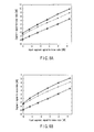
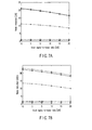
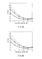
- FIGS. 6A to 7B The result of the average SEGSNR and NR calculated at various signal-to-noise ratios in two noise states (50 km/h and 100 km/h) are shown in FIGS. 6A to 7B . Also, the result of LSD is shown in FIG. 8 . The values of the experiment results are averaged over all the utterances in the respective noise states. The performance is estimated in the microphone recording, the beam former output and the output of the post-filter according to the invention.
- FIGS. 6A , 7A and 8A represent the cases in which the vehicle is travelling at 50 km/h; FIGS. 6B , 7B and 8B , the cases at 100 km/h.
- the rectangle designates the output of the beam former, the rhomb the output of the Zelinski post-filter, the (+) mark the output of the McCowan post-filter, the triangle the output of the single-channel Wiener post-filter, and the circle the output of the post-filter according to the invention.
- the symbol X designates the average logarithmic spectrum distance (LSD) of the signal as it is recorded without executing any process.
- the beam former alone and the Zelinski post-filter fail to exhibit a sufficient performance in suppressing the low-frequency noise component and produce no result of SEGSNR improvement or noise reduction.
- the McCowan post-filter using the appropriate coherence function of the noise field as a parameter improves SEGSNR considerably.
- the single-channel Wiener post-filter produces the improvement of SEGSNR and NR higher than the Zelinski and McCowan post-filters.
- the post-filter according to the invention produces SEGSNR and NR equivalent to the single-channel post-filter under all the test conditions and exhibits the highest performance.
- the beam former alone and the Zelinski post-filter reduce the LSD for all the signal-to-noise ratios more with the filter than without the filter.
- the single-channel Wiener post-filter reduces the voice distortion at a low signal-to-noise ratio but increases the distortion at a high signal-to-noise ratio.
- the proposed method and the McCowan post-filter indicate the lowest LSD for almost all signal-to-noise ratios.
- FIG. 9D shows an output of the beam former. As shown in FIG. 5 , the noise suppression has a weak point at low frequencies, and large low-frequency noise exists.
- FIG. 9E an output of the Zelinski post-filter shown in FIG. 9E is shown to provide a very limited performance at low frequencies because of the high correlation characteristic of the noise in the low-frequency region.
- FIG. 9F shows that the McCowan post-filter suppresses the noise also in the low-frequency region. Nevertheless, the residual noise exists due to the difference between the estimated coherence function and the actual coherence function.
- the single-channel Wiener post-filter as shown in FIG. 9G , provides a voice distortion.
- FIG. 9H shows a post-filter according to the invention and indicates that the diffusive noise can be suppressed without adding the voice distortion.
- the informal hearing test has substantiated the superiority of the post-filter according to the invention over the other post-filters.
- the basic assumption (diffused noise field) for the post-filter according to the invention in a practical environment is more rational than that for the Zelinski post-filter (non-correlated noise field). Therefore, the post-filter according to the invention is superior to the Zelinski post-filter. Further, the post-filter according to the invention succeeds in reducing the high correlation noise component of low frequencies.
- the McCowan post-filter is determined based on the coherence function of the noise field.
- the performance therefore, depends to a large measure on the accuracy of the assumed coherence function.
- the difference between the assumption and the actual coherence function brings about the performance deterioration.
- the hybrid post-filter according to the invention only the transition frequency is used to distinguish the correlated noise and the non-correlated noise. Regardless of the actual instantaneous value of the coherence function, the effect attributable to the error between the coherence functions is reduced.
- the hybrid post-filter according to the invention is superior to the single-channel Wiener post-filter used in all the frequency bands.
- the single-channel Wiener post-filter based on the measurement of the noise characteristic cannot substantially meet the requirement of the unsteady noise source even with a soft decision mechanism.
- the multi-channel technique based on the estimation of the autocorrelation and cross-correlation spectral densities, however, provides a theoretically desirable performance also against the unsteady noise.
- the corrected Zelinski post-filter according to the invention provides this performance in a complete form in each frequency division of the high-frequency region.
- the post-filter according to the invention is configured by coupling the corrected Zelinski post-filter for the high-frequency region and the single-channel Wiener filter for the low-frequency region to each other.
- the post-filter according to the invention as compared with other algorithms, has the following advantages.
- the high correlated noise and the low correlated noise in the diffused noise field can be effectively reduced.
- the problems described in the related column for problem solution can be solved even if several constituent elements are deleted from all the constituent elements described in each embodiment, for example, and in the case where the effects of the invention described above can be obtained, the configuration with the particular constituent elements deleted can be extracted as an invention.
- the high correlated noise and the low correlated noise in the diffused noise field can be effectively reduced.
Landscapes
- Engineering & Computer Science (AREA)
- Computational Linguistics (AREA)
- Quality & Reliability (AREA)
- Signal Processing (AREA)
- Health & Medical Sciences (AREA)
- Audiology, Speech & Language Pathology (AREA)
- Human Computer Interaction (AREA)
- Physics & Mathematics (AREA)
- Acoustics & Sound (AREA)
- Multimedia (AREA)
- Circuit For Audible Band Transducer (AREA)
- Obtaining Desirable Characteristics In Audible-Bandwidth Transducers (AREA)
Abstract
Description
- The present invention relates to a post-filter for a microphone array.
- Many applications including cell phones and automatic voice recognition systems are desirably based on a hands-free technique due to its utility and flexibility. One of the critical problems for this technique is that the reliability of a signal received by a microphone located at a far point is extremely reduced by various types of noise. As a solution to this problem, the use of a spatial filter having a microphone array for suppressing noise arriving from a direction other than a predetermined direction is considered. The microphone array produces a high-quality speech signal and has considerable superiority in noise reduction.
- A proposition made recently is described in Document 1: J. Bitzer, K. U. Simmer and K. D. Kammeyer, "Multi-microphone Noise Reduction Techniques as Front-end Devices for Speech Recognition", Speech Communication, vol. 34, pp. 3-12, 2001. This proposition indicates that assuming that a desired speech signal and noise are not correlated, a multi-channel Wiener filter provides an optimum solution minimizing a square error of an output with respect to a broadband input. Also,
Document 1 indicates that the multi-channel Wiener filter can be decomposed into a minimum variance distortionless response (MVDR) beam former and the following Wiener post-filter. Generally, the multi-channel Wiener filter generates an output with a signal-to-noise ratio higher than in the case where only the MVDR beam former is used. In the practical noise environment, therefore, the addition of post-filtering is required to improve the performance of the microphone array. - With regard to the aforementioned post-filtering, various post-filtering techniques have been proposed (Document 2: R. Zelinski, "A Microphone Array with Adaptive Post-filtering for Noise Reduction in Reverberant Rooms", in Proc. IEEE Int. Conf. on Acoustic, Speech, Signal Processing, vol. 5, pp. 25782581, 1988., Document 3: I. A. McCowan and H. Bourlard, "Microphone Array Post-filter Based on Noise Field Coherence", IEEE Trans. on Speech and Audio Processing, vol. 11, No. 6, pp. 709-716, 2003., Document 4: I. Cohen and B. Berdugo, "Microphone Array Post-filtering for Non-stationary Noise Suppression", in Proc. IEEE Int. Conf. Acoustic Speech Signal Processing, pp. 901-904, May 2002., and Document 5: I. Cohen, "Multi-channel Post-filtering in Non-stationary Noise Environments", IEEE Trans. Signal Processing, Vol. 52, No. 5, pp. 1149-1160, 2004). One multi-channel post-filter widely used was first proposed by Zelinski. This post-filter (hereinafter referred to as a "Zelinski post-filter") assumes a noise field in which noise instances for different microphones are totally uncorrelated. This assumption, however, is rarely satisfied in the actual environment, or especially, in the case where microphones are located close to each other or in a low-frequency range high in correlation between noise instances.
- In order to suppress the noise instances having a high correlation, a proposition has been made to couple a general sidelobe canceller (GSC) to a Zelinski post-filter (Document 6: S. Fischer, K. D. Kammeyer, and K. U. Simmer, "Adaptive Microphone Arrays for Speech Enhancement in Coherent and Incoherent Noise Fields", in Proc 3rd joint meeting of the Acoustical Society of America and the Acoustical Society of Japan, Honolulu, Hawaii, 1996). It is pointed out, however, that both the GSC and the Zelinski post-filter have no satisfactory behavior in the low-frequency area. For this reason, it has been proposed to use the Zelinski post-filter to reduce low correlated noise components at high frequency and to conduct a spectral subtraction to reduce high correlated noise components at low frequency (Document 7: J. Meyer and K. U. Simmer, "Multi-channel Speech Enhancement in a Car Environment Using Wiener Filtering and Spectral Subtraction", in Proc. IEEE Int. Conf. on Acoustic, Speech, Signal Processing, Munich, Germany, pp. 21-24, 1997). This proposition, however, contradicts with the basic configuration of the multi-channel Wiener post-filter on the one hand and requires a voice activity detector (VAD) for spectral subtraction on the other.
- Now, the multi-channel Wiener post-filter and the problems to be solved are explained. After that, the Zelinski post-filter and the McCowan post-filter used for comparison are explained.
- In a microphone array having M sensors in a noise environment, an mth observation signal xm(t) is formed of two components. A first signal is a desired one converted by an impulse response between a desired sound source and the mth sensor. A second signal is an additional noise nm(t). From this, the receive signal is given by Equation 1:

where m = 1, 2, ... ,M, and * is a convolution operator. By application of the short-time Fourier transform (STFT), a signal observed in time and frequency domains can be expressed as shown below:
where k is a frequency index and 1 is a frame index.


- The object here is to estimate the desired signal from the observed signals including the noise instances. By using this matrix expression, an estimated output signal T(k,l) is given by the equation below:

where W(k,l) is a weight coefficient and the superscript H is a complex conjugate inversion. - In response to a request to minimize a mean square error between the desired signal and the estimation thereof, the optimum weight coefficient is obtained and so is the multi-channel Wiener filter. Assuming that the desired signal and the noise are not correlated, the multi-channel Wiener filter can be further decomposed into a MVDR beam former and a Wiener post-filter.

- In Equation 7, above, the first term represents the MVDR beam former, and the second term represents the Wiener post-filter. The MVDR beam former estimates the distortionless MMSE of the desired signal in a predetermined direction. By reducing the remaining noise further in the Wiener post-filter, the noise reduction capability can be improved to thereby generate a higher signal-to-noise ratio.
- As the MVDR beam former, proposed are several adaptive algorithms such as a Frost beam former (Document 8: O. L. Frost, "An algorithm for linearly constrained adaptive array processing", in Proc. IEEE, vol. 60, pp. 926-935, 1972) and a generally-used side lobe canceler (GSC) and several non-adaptive algorithms such as a super-directive beam former on the assumption of a diffused noise field.
- The discussion below assumes that a microphone array is arranged in advance in a desired signal direction within a range not departing from the general applicability and in order to process the same desired voice signal on each microphone, the multi-channel input is scaled. In the process, a time delay compensation output is given as follows.

- Now, two post-filters called the Zelinski post-filter and the McCowan post-filter are briefly explained.
- The Zelinski post-filter provides a solution of the Wiener filter in the noise field where noise instances are completely non-correlated, using the autocorrelation spectral density and cross-correlation spectral density estimated. As long as the desired signal and the noise are not correlated, and the noise instances for different microphones, though identical in power density, are not correlated, then the autocorrelation and cross-correlation spectral densities φxixi(k,l) and φxixj(k,l) can be simplified.


- Based on the simplistic expression (
Equations 9 and 10) of the autocorrelation and cross-correlation spectral densities, the Zelinski post-filter can be formulated:
where the real number R{ } and the mean calculation (for all the sensor pairs) contribute to an improved tenacity of the post-filter against an estimation error. The autocorrelation and cross-correlation spectral densities can be estimated by the microphone signal scaled. - Actually, however, the basic assumption of the Zelinski post-filter that the noise instances for the respective microphones are not correlated is rarely satisfied in the practical environment. Taking this fact into consideration, McCowan has relaxed the assumption that the noise instances for the respective microphones are not correlated and has proposed an assumption that the noise instances for the respective microphones have the same power spectral density and are related to each other and that the magnitude of the correlation is given by a coherence function.
- Then, under the assumption that the desired speech signal and the noise are not correlated and the relaxed assumption of the correlation between the noise instances, the autocorrelation and cross-correlation spectral densities of the multiple channels are given by the equations described below. In these equations, Γninj(k,l) is a complex coherence function (described later in Equation 17).
- φxixi(k, l), φxjxj(k, l) and φxixj(k, l) can be simplified as follows.


- Based on these expressions, the spectral density φss_(k, l) of the speech power providing the numerator of the Wiener post-filter can be expressed as

- The McCowan post-filter can be expressed as

- The McCowan post-filter presupposes the use of the multi-channel recording in an office, and is proposed to achieve an improved performance as compared with the Zelinski post-filter in this environment. The performance of the McCowan post-filter is expected to be reduced, however, in the presence of a difference between an estimated coherence function and the actual coherence function.
- An object of the present invention is to provide a novel post-filter having a hybrid structure in a diffused noise field.
- The diffused noise field like the environment in a reverberated room or vehicle compartments is proposed as a rational model of many practical noise environments. In the diffused noise field, low-frequency noise instances are correlated high and high-frequency noise instances are correlated low. Taking these characteristics into consideration, according to this invention, there are employed a multi-channel Wiener post-filter for high-frequency (correlated low) noise instances and a single-channel Wiener post-filter for low-frequency (correlated high) noise instances. In high-frequency regions, a corrected Zelinski post-filter sufficiently considering and utilizing the correlation between the noise instances for different microphone pairs is employed. In the low-frequency regions, on the other hand, a single-channel Wiener post-filter for further reducing the "musical noise" due to a decision directivity signal-to-noise ratio estimation mechanism is employed. The post-filter according to this invention theoretically has a basic configuration of the multi-channel Wiener post-filter and can effectively reduce the high correlated noise instances and low correlated noise instances in the diffused noise field.
- The post-filter according to an aspect of the invention includes a microphone array having at least two microphones which are supplied with a voice signal, a beam former which forms the voice signal input from the microphone array, a divider which divides a target sound containing noise instances input from the microphone array into at least two frequency bands, a first filter which estimates a filter gain with the noise instances not correlated between the microphones, a second filter which estimates a filter gain of one microphone in the microphone array or a mean signal of the microphone array, an adder which adds the outputs of the first and second filters, and means for reducing the noise instances based on the outputs from the adder and the beam former.
-
-
FIG. 1 is a graph showing an MSC function of a complete diffused noise field against frequency. -
FIG. 2 is a block diagram showing a post-filter according to the present invention. -
FIG. 3 is a block diagram showing a general configuration of a corrected Zelinski post-filter. -
FIG. 4 is a block diagram showing a general configuration of a single-channel Wiener post-filter. -
FIG. 5 is a graph showing the relationship between the directivity factor and frequency. -
FIG. 6A is a graph showing a test result of the averaged SEGSNR calculated in two noise states at various signal-to-noise ratios. -
FIG. 6B is a graph showing the test result of the averaged SEGSNR calculated in two noise states at various signal-to-noise ratios. -
FIG. 7A is a graph showing a test result of the averaged NR calculated in two noise states at various signal-to-noise ratios. -
FIG. 7B is a graph showing the test result of the averaged NR calculated in two noise states at various signal-to-noise ratios. -
FIG. 8A is a graph showing a test result of the averaged LSD calculated in two noise states at various signal-to-noise ratios. -
FIG. 8B is a graph showing the test result of the averaged LSD calculated in two noise states at various signal-to-noise ratios. -
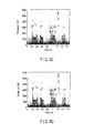
FIG. 9A is a graph showing an example of measurement corresponding to the typical Japanese utterance "Douzo Yoroshiku" ("How do you do?") of a voice spectrogram in an environment of an automobile travelling at 100 km/h. -
FIG. 9B is a graph showing the example of measurement corresponding to the typical Japanese utterance "Douzo yoroshiku" ("How do you do?") of the voice spectrogram in the environment of an automobile travelling at 100 km/h. -
FIG. 9C is a graph showing the example of measurement corresponding to the typical Japanese utterance "Douzo yoroshiku" ("How do you do?") of the voice spectrogram in the environment of an automobile travelling at 100 km/h. -
FIG. 9D is a graph showing the example of measurement corresponding to the typical Japanese utterance "Douzo yoroshiku" ("How do you do?") of the voice spectrogram in the environment of an automobile traveling at 100 km/h. -
FIG. 9E is a graph showing the example of measurement corresponding to the typical Japanese utterance "Douzo yoroshiku" ("How do you do?") of the voice spectrogram in the environment of an automobile traveling at 100 km/h. -
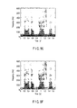
FIG. 9F is a graph showing the example of measurement corresponding to the typical Japanese utterance "Douzo yoroshiku" ("How do you do?") of the voice spectrogram in the environment of an automobile traveling at 100 km/h. -
FIG. 9G is a graph showing the example of measurement corresponding to the typical Japanese utterance "Douzo yoroshiku" ("How do you do?") of the voice spectrogram in the environment of an automobile traveling at 100 km/h. -
FIG. 9H is a graph showing the example of measurement corresponding to the typical Japanese utterance "Douzo yoroshiku" ("How do you do?") of the voice spectrogram in the environment of an automobile traveling at 100 km/h. - An embodiment of the invention will be explained with reference to the drawings. In the description that follows, first, an explanation is given about a coherence function and an application thereof in a model noise field. Then, a hybrid post-filter in a diffused noise field is explained, and finally, the advantages of a post-filter according to the invention are described.
- A complex coherence function defined by the equation below is widely used to characterize the noise field.

where φxixj(k,l) is a cross-correlation spectral density between two signals xi(t) and xj(t); and φxixi(k,l) and φxjxj(k,l) are autocorrelation spectral densities of the signals xi(t) and xj(t), respectively. A magnitude-squared coherence (MSC) function, which is another important means, is defined as a square of an amplitude of the complex coherence function given by MSC (k, 1) = |Γxixj(k, l)|2 used in this specification to analyze the noise field. - The diffused noise field, which is one of the basic assumptions in this specification, is shown as a rational model for many actual noise environments. The diffused noise field is characterized by the MSC function described below:

where d is a distance between adjacent microphones and c is a sound velocity. An MSC function of a complete diffused noise field against frequency is shown inFIG. 1 . FromFIG. 1 , several characteristics of the diffused noise field described below can be easily determined. - 1. The MSC function is dependent on frequency but not on time.
- 2. Noise instances for different microphones are correlated high at low frequency and correlated low at high frequency.
- In order to divide a spectrum into a low correlated portion and a high correlated portion, a transition frequency ft for dividing the two regions is selected as a first minimum value given as ft = c/(2d). Apparently, the sound velocity c is regarded as a constant, and therefore, the transition frequency is determined simply by the distance d between the two microphones.
- In order to formulate the post-filter according to this invention, the following assumptions are made:
- (1) A desired speech signal and noise are not correlated for each microphone.
- (2) The power spectral density of noise is the same for each microphone.
- (3) Noise instances for different microphones constitute diffused noise.
- Actually, it has been confirmed that the first assumption is used for a normal voice signal processing, and the second and third assumptions are realized in many actual noise environments.
- A hybrid post-filter for improving the noise reduction performance of the post-filter is explained below. As a post-filter, a corrected Zelinski post-filter for a high-frequency region and a single-channel Wiener post-filter for a low-frequency region are used.
FIG. 2 is a block diagram showing a post-filter according to the invention. Also,FIG. 3 is a block diagram showing a general configuration of the corrected Zelinski post-filter.FIG. 4 is a block diagram showing a general configuration of the single-channel Wiener post-filter. - As shown in
FIG. 2 , the post-filter according to the invention includes a microphone array 10 (hereinafter sometimes referred to simply as "microphone"), afast Fourier transformer 11, atime matching unit 12, a beam former 13, afrequency band divider 14, a corrected Zelinski filter gain estimator 20 (corrected Zelinski post-filter), a single-channelfilter gain estimator 30, anadder 40, afilter 41, adelay unit 42 and an inversefast Fourier transformer 50. - As shown in
FIG. 3 , the corrected Zelinskifilter gain estimator 20 includes a cross-correlation spectraldensity computing unit 21, an averagingunit 22, an autocorrelation spectraldensity computing unit 23, an averagingunit 24 and adivider 25. Also, as shown inFIG. 4 , the single-channelfilter gain estimator 30 includes an averagingunit 31, a noisevariance updating unit 32, an a posteriori signal-to-noiseratio computing unit 33, adelay unit 34, an a priori signal-to-noiseratio computing unit 35, aSAM computing unit 36 and a single-channel Wiener filter gain estimator 37 (single-channel Wiener post-filter). - In the aforementioned configuration, based on the assumption that the noise instances for the
microphones 10 are not correlated to each other, a mean square error between the voice in the non-correlated noise field and the estimation thereof is required to be minimized. As described above, the autocorrelation and cross-correlation spectral densities of the multi-channel input contain the correlation noise component. In the case where the noise correlation used for estimating the autocorrelation and cross-correlation spectral densities of the multi-channel input is small, therefore, it is considered possible to suppress the performance reduction. - As shown in
FIG. 1 , the noise components of different microphones, which are not correlated in the diffused noise field, exist only in the frequencies not lower than the transition frequency ft. The transition frequency is determined in accordance with the distance between the microphones, and therefore, the microphones having different distances between elements are characterized by different transition frequencies. Specifically, non-correlated noise instances exist in different frequency regions in different microphones having different intervals between elements. Further, with regard to a given frequency, the noise instances are not correlated with each other only for specified microphones, but for all the microphones in general. As a result, the corrected Zelinski post-filter can be obtained by calculating the autocorrelation and cross-correlation spectral densities of the multi-channel input of the related microphone pair. This is specifically explained below. - The transition frequency is determined in advance in accordance with the microphone arrangement of the microphone array. Specifically, consider an M sensor array with sensors i and j (i, j ≤ M) distant by dij from each other and having the intervals between elements. It has M(M-1)/2 microphone pairs for determining the transition frequency of M(M-1)/2. In the process, the transition frequency can be calculated as ft,ij = c/(2dij). In this case, the intervals between mutual elements are the same for several microphones, and therefore, the transition frequency is also the same. In the case where M microphones are arranged equidistantly on the straight line, for example, the M(M-1)/2 microphones have (M-1) different element intervals, and therefore, (M-1) different transition frequencies indicated by ft 1, ft 2, ... , ft M-1 can be determined. Incidentally, as long as no general applicability is lost, the relation between transition frequencies may be further assumed to be ft 1 < ft 2 <, ... , < ft M-1. Incidentally, unless M microphones are arranged equidistantly or linearly, all the M(M-1)/2 microphone pairs can be arranged at different intervals, in which case M(M-1)/2 transition frequencies can be selected.
- For example, the voice input from the
microphone 10 is subjected to Fourier transform at thefast Fourier transformer 11. With regard to the signal after Fourier transform, the time shift of the input signals for the same voice between themicrophones 10 is corrected by thetime matching unit 12. In this case, the processes in thefast Fourier transformer 11 and thetime matching unit 12 may be executed in reverse order. - Next, the temporally matched voice signals are input to the
frequency band divider 14, which divides the entire frequency band into M subbands B0, B1, ... , BM-1 at (M-1) different transition frequencies ft 1, ft 2, ... , ft M-1. Of the M subbands, the (M-1) subbands B1, .... BM-1 are input to the corrected Zelinskifilter gain estimator 20. The temporally matched voice signals are input also to the beam former 13 and after beam forming, input to thefilter 41. - With regard to the (M-1) subbands input to the corrected Zelinski
filter gain estimator 20, the cross-correlation spectral density is calculated by the cross-correlation spectraldensity computing unit 21, and the average value thereof is determined by the averagingunit 22. In the averaging operation in the averagingunit 22, not all the inputs but the autocorrelation (cross-correlation) spectral densities for the microphone pairs with the noise instances not correlated in the particular band are selected and averaged out. Also, the autocorrelation spectral density is calculated in the autocorrelation spectraldensity computing unit 23, and the average value thereof is determined in the averagingunit 24. Incidentally, in the cross-correlation spectraldensity computing unit 21 and the autocorrelation spectraldensity computing unit 23, the spectral density of the noise is determined in the manner described below. - Assume that the noise instances for the microphone pair Qm for the frequencies of the subband Bm (1 ≤ m ≤ M-1) are not correlated. In this case, the autocorrelation and cross-correlation spectral densities of the multi-channel input are given from


- From these spectral densities, the spectral densities of the desired speech and the noise can be estimated.
- Then, the auto and cross spectral densities averaged by the averaging
units divider 25 thereby to output a filter gain (gain function) in the high-frequency band. In this case, since the Zelinski post-filter determines the filter gain by averaging the autocorrelation (cross-correlation) spectral densities for all the microphone pairs, data with a high noise correlation (not covered by the assumption) is undesirably included. As a result, the estimation of the filter gain fails to be robust. In the corrected Zelinski post-filter, on the other hand, only data low in noise correlation (covered by the assumption) is selected as a set Qm and averaged within that range, resulting in a high robustness. In this case, the gain function of the corrected Zelinski post-filter can be given as
- In the foregoing description, the determination of the transition frequency is dependent only on the arrangement of the micro array, but not on the input signal. Also, the selection of the microphone pair included in the procedure of estimating the autocorrelation and cross-correlation spectral densities contributes to the reduction in the cost of calculation of the corrected Zelinski post-filter.
- The subband B0 from each
microphone 10, on the other hand, is input to the single-channelfilter gain estimator 30. In the case where the noise instances for all the microphones are correlated high, even the use of the corrected Zelinski post-filter would fail to estimate the autocorrelation spectral density of the desired voice signal from the autocorrelation and cross-correlation spectral densities of the multi-channel input. At low frequencies, therefore, the single-channel technique is employed to estimate the Wiener post-filter. - First, a subband B0 input to the single-channel
filter gain estimator 30 is averaged between channels by the averagingunit 31. The subband B0 thus averaged is input to the noisevariance updating unit 32 and the a posteriori signal-to-noiseratio computing unit 33. The noisevariance updating unit 32 executes the update process based on the signals from the averagingunit 31 and theSAP computing unit 36, and outputs an estimated noise spectrum to the a posteriori signal-to-noiseratio computing unit 33 and thedelay unit 34. The apriori computing unit 35 executes various calculating operations described in detail later from the a posteriori signal-to-noiseratio computing unit 33. The single-channel Wienerfilter gain estimator 37, based on the signal from the a priori signal-to-noiseratio computing unit 35, outputs a filter gain (gain function) in the low-frequency band. - In the configuration described above, the gain function of the Wiener post-filter can be rewritten as follows:

where E[] is an expectation operator and SNRpriori(k,l) is an a priori signal-to-noise ratio defined as SNRpriori(k,l) = E[|S(k,l)|2]/E[|N(k,l)2]. - The estimation of the a priori signal-to-noise ratio (SNRpriori(k,l)) calculated by the a priori signal-to-noise
ratio computing unit 35 is updated by the decision directivity estimation mechanism described below.
- In Equation (23), α (0 < α < 1) is a forgetting factor, and SNRpost(k,l) is an a posteriori signal-to-noise ratio calculated by the a posteriori signal-to-noise
ratio computing unit 33 and expressed as SNRpost(k,l) = |X(k,l)|2/E[|N(k,l)2|]. As a result, the decision directivity estimation mechanism described above considerably reduces the "musical noise". - To improve the performance of the single-channel Wiener post-filter, the very important point here is to estimate the noise power spectral density E[|N(k,l)|2] with high accuracy. This noise power spectral density is estimated with the soft decision base approach described below.

- In Equation (24), β (0 < β < 1) is a forgetting factor for controlling an update rate of noise estimation.
- As far as the presence of the voice is not determined, the second term on the right side of Equation (24) is estimated as a spectral density of the signal observed using Equation (25).

- In Equation (25), q(k,l) is a speech absence probability, and |X(k, l)|2 is an average spectral density of the individual noise instances at each sensor.

- The reason why the average spectral density of individual noise instances at each sensor is calculated is that the concentration on one sensor would be liable to cause an erroneous measurement due to an estimation error. Assuming the complex Gauss statistical value model, the application of Bayes theorem and the theorem of stochastic total sum gives the speech absence probability according to the following formula.

- In Equation (26), q'(k,l) is an a priori speech absence probability and selected at an appropriate value experimentally.
- The filter gains (gain functions) in the high-frequency band and the low-frequency band determined as described above are added in the
adder 40 and the result of addition is output to thefilter 41. Thefilter 41 outputs the signal reduced in noise in the high-frequency band and the low-frequency band from the outputs of the beam former 13 and theadder 40 to thedelay unit 42 and the inversefast Fourier transformer 50. The inversefast Fourier transformer 50 subjects the input signal to the inverse Fourier transform, and outputs it to a voice recognition unit, for example, in the subsequent stage. Also, the signal output to thedelay unit 42 is used for calculating the gain function in the single-channelfilter gain estimator 30. - The post filter according to this invention theoretically follows the framework of the multi-channel Wiener post-filter and can be regarded as the Wiener post-filter in the true sense of the word. The post filter indicated by
Equation 22 in the low-frequency range is apparently a Wiener filter. In the high-frequency range, on the other hand, the noise instances used for estimation in the corrected Zelinski post-filter are not correlated, and therefore, the cross-correlation spectral density of the multi-channel input provides a more accurate autocorrelation spectral density estimation of the speech. Therefore, the corrected Zelinski post-filter employed in the high-frequency range can be regarded as a Wiener post-filter. - It should be noted that the post-filter according to the invention configured as described above provides a more general expression as an optimum post-filter for the microphone array. In the completely non-correlated noise field, the post-filter according to the invention becomes a Zelinski post-filter simply by setting the transition frequency to zero. In the noise field with all the noise instances completely correlated, the single-channel Wiener post-filter is realized simply by setting the transition frequency of the post-filter according to the invention to the highest frequency.
- In order to confirm the effectiveness of the post-filter according to the invention in the diffused noise field, the post-filter according to the invention was compared with the Zelinski post-filter, the McCowan post-filter and other conventional post-filters including the single-channel Wiener post-filter in various vehicle noise environments. The beam former is first used for the multi-channel noise. The output of the beam former is further upgraded in function by the post-filter according to the invention. The performance is evaluated by objective and subjective means.
- The configuration for the experiment is as follows:
- In order to estimate the performance of the post-filter according to this invention in the actual vehicle environment, a linear array including three equidistantly arranged microphones having the element interval of 10 cm was mounted on a sun visor of a vehicle. The array is arranged about 50 cm away from the driver on the front of the driver.
- Multi-channel noise was recorded for all the channels at the same time while the vehicle was traveling along a freeway at 50 and 100 km/h. The noise mainly includes engine noise, air-conditioner noise and road noise. A clear speech signal including 50 Japanese utterances was retrieved from ATR database. First, both the speech signal and noise were extracted again at 12 kHz with an accuracy of 16 bits. The clear speech signal and the actual multi-channel in-vehicle noise were mixed artificially at different global signal-to-noise ratios of -5 and 20 dB. Thus, multi-channel noise was generated. This generation procedure has the following advantages:
- (1) The time delay is considered to have been ideally compensated for.
- (2) The mixing conditions are positively measured, and therefore, the performance estimation using objective means is facilitated.
- By comparing the theoretical sinc function shown in
FIG. 1 with the measurement MSC function calculated by recording the actual noise instances, the effectiveness of the diffused noise field was investigated. It can be understood fromFIG. 1 that in spite of an instantaneous change, the measurement MSC function follows the trend of the theoretical sinc function. This value satisfies the assumption of the diffused noise field used in the post-filter according to the invention. - The beam forming filter is realized by a super-directivity beam former providing a solution for the MVDR beam former in the diffused noise field. A gain function of the super-directivity beam former which is a function of the frequency k is given as

- A directivity factor (DI) indicating the noise reduction capability of the array against the diffused noise source is expressed as

- A relation between this directivity factor and the frequency is shown in
FIG. 5 . It is apparent fromFIG. 5 that the super-directivity beam former has no effect of suppressing the low-frequency noise component. - In order to estimate the post-filter according to the invention objectively, three objective voice quality measurements of a segment signal-to-noise ratio (SEGSNR), a noise reduction ratio (NR) and a log spectrum distance (LSD) were used as described below.
- The segment signal-to-noise ratio (SEGSNR) is objective estimation means widely used for the noise reduction and the voice enhancement algorithm. SEGSNR is defined as the ratio between the power of clear speech and noise included in speech containing noise or noise included in a signal with noise reduced by the proposed algorithm, and given as:

where s(), s_() are signals obtained by suppressing a reference speech signal and noise processed with the algorithm tested. Also, L and K designate the number of frames of the signal and the number of samples per frame (equal to the length of STFT), respectively. - The noise reduction ratio (NR) is used for estimating the noise reduction performance of the proposed algorithm. In the absence of a voice, NR is defined as a ratio between the power of an input containing noise and the power of a signal enhanced, and expressed as:

where φ is a set of frames lacking a voice; |φ| is a density; and X(k,1) and s_(k,l) are noise and an enhanced speech signal, respectively. - The log spectrum distance (LSD) is often used to estimate the distortion of a desired voice signal. LSD is defined as the distance between the logarithmic spectrum of clear speech and the logarithmic spectrum of noise or a signal enhanced by the proposed algorithm, and given as:

where ψ is a set of frames having a voice, and |ψ| is the base thereof. S(k, l) and S_(k, l) are spectra of a reference clear signal and an enhanced voice signal, respectively. - The result of the average SEGSNR and NR calculated at various signal-to-noise ratios in two noise states (50 km/h and 100 km/h) are shown in
FIGS. 6A to 7B . Also, the result of LSD is shown inFIG. 8 . The values of the experiment results are averaged over all the utterances in the respective noise states. The performance is estimated in the microphone recording, the beam former output and the output of the post-filter according to the invention. Incidentally,FIGS. 6A ,7A and8A represent the cases in which the vehicle is travelling at 50 km/h;FIGS. 6B ,7B and8B , the cases at 100 km/h. Also, in the symbols in the drawings, the rectangle designates the output of the beam former, the rhomb the output of the Zelinski post-filter, the (+) mark the output of the McCowan post-filter, the triangle the output of the single-channel Wiener post-filter, and the circle the output of the post-filter according to the invention. InFIG. 8 , the symbol X designates the average logarithmic spectrum distance (LSD) of the signal as it is recorded without executing any process. - As shown in
FIGS. 6A to 7B , the beam former alone and the Zelinski post-filter fail to exhibit a sufficient performance in suppressing the low-frequency noise component and produce no result of SEGSNR improvement or noise reduction. This indicates the result confirming the forgoing explanation. The McCowan post-filter using the appropriate coherence function of the noise field as a parameter improves SEGSNR considerably. In all the noise states, however, the single-channel Wiener post-filter produces the improvement of SEGSNR and NR higher than the Zelinski and McCowan post-filters. The post-filter according to the invention produces SEGSNR and NR equivalent to the single-channel post-filter under all the test conditions and exhibits the highest performance. - With regard to the LSD results shown in
FIGS. 8A and 8B , the beam former alone and the Zelinski post-filter reduce the LSD for all the signal-to-noise ratios more with the filter than without the filter. The single-channel Wiener post-filter reduces the voice distortion at a low signal-to-noise ratio but increases the distortion at a high signal-to-noise ratio. The proposed method and the McCowan post-filter, on the other hand, indicate the lowest LSD for almost all signal-to-noise ratios. - The subjective performance evaluation of the post-filter according to the invention was effectively conducted by using the voice spectrogram and by an informal hearing test. A typical example of measurement of the voice spectrogram corresponding to the Japanese "Douzo yoroshiku" meaning "How do you do?" in the environment inside the vehicle travelling at 100 km/h is shown in
FIGS. 9A to 9H .FIGS. 9A to 9C show an original clear speech signal for a first microphone, noise for the first microphone and the noise signal (signal-to-noise ratio = 10 dB) for the first microphone, respectively.FIG. 9D shows an output of the beam former. As shown inFIG. 5 , the noise suppression has a weak point at low frequencies, and large low-frequency noise exists. Also, an output of the Zelinski post-filter shown inFIG. 9E is shown to provide a very limited performance at low frequencies because of the high correlation characteristic of the noise in the low-frequency region.FIG. 9F shows that the McCowan post-filter suppresses the noise also in the low-frequency region. Nevertheless, the residual noise exists due to the difference between the estimated coherence function and the actual coherence function. The single-channel Wiener post-filter, as shown inFIG. 9G , provides a voice distortion.FIG. 9H shows a post-filter according to the invention and indicates that the diffusive noise can be suppressed without adding the voice distortion. The informal hearing test has substantiated the superiority of the post-filter according to the invention over the other post-filters. - As described above, the basic assumption (diffused noise field) for the post-filter according to the invention in a practical environment is more rational than that for the Zelinski post-filter (non-correlated noise field). Therefore, the post-filter according to the invention is superior to the Zelinski post-filter. Further, the post-filter according to the invention succeeds in reducing the high correlation noise component of low frequencies.
- The McCowan post-filter is determined based on the coherence function of the noise field. The performance, therefore, depends to a large measure on the accuracy of the assumed coherence function. The difference between the assumption and the actual coherence function brings about the performance deterioration. In the hybrid post-filter according to the invention, however, only the transition frequency is used to distinguish the correlated noise and the non-correlated noise. Regardless of the actual instantaneous value of the coherence function, the effect attributable to the error between the coherence functions is reduced.
- The hybrid post-filter according to the invention is superior to the single-channel Wiener post-filter used in all the frequency bands. The single-channel Wiener post-filter based on the measurement of the noise characteristic cannot substantially meet the requirement of the unsteady noise source even with a soft decision mechanism. The multi-channel technique based on the estimation of the autocorrelation and cross-correlation spectral densities, however, provides a theoretically desirable performance also against the unsteady noise. The corrected Zelinski post-filter according to the invention provides this performance in a complete form in each frequency division of the high-frequency region.
- As described above, according to the invention, a post-filter against the microphone array has been proposed assuming a diffused noise field. The post-filter according to the invention is configured by coupling the corrected Zelinski post-filter for the high-frequency region and the single-channel Wiener filter for the low-frequency region to each other.
- The post-filter according to the invention, as compared with other algorithms, has the following advantages.
- (1) Theoretically, the post-filter according to the invention is a Wiener post-filter, and therefore, follows the framework of the multi-channel Wiener post-filter.
- (2) Actually, in the post-filter according to the invention, the noise is reduced, and the desired speech is effectively estimated as compared with other algorithms in various vehicle noise environments.
- According to this invention, the high correlated noise and the low correlated noise in the diffused noise field can be effectively reduced.
- The invention is not limited to the embodiments described above, and can be embodied in various modifications without departing from the spirit and scope of the invention. Further, the embodiments described above include various stages of the invention, and various inventions can be extracted by appropriate combinations of a plurality of constituent elements disclosed.
- Also, according to the invention, the problems described in the related column for problem solution can be solved even if several constituent elements are deleted from all the constituent elements described in each embodiment, for example, and in the case where the effects of the invention described above can be obtained, the configuration with the particular constituent elements deleted can be extracted as an invention.
- According to the invention, the high correlated noise and the low correlated noise in the diffused noise field can be effectively reduced.
Claims (5)
- A post-filter comprising:a microphone array including at least two microphones to which a voice signal are input;a beam former which forms the voice signal input from the microphone array;a divider which divides a target sound containing noise input from the microphone array into at least two frequency bands at a predetermined frequency;a first filter which estimates a filter gain with the noise non-correlated between the microphones;a second filter which estimates a filter gain of one microphone of the microphone array or an average signal of the microphone array;an adder which adds the outputs from the first filter and the second filter to each other; andmeans for reducing the noise based on the outputs from the adder and the beam former.
- The post-filter according to claim 1, wherein the first filter is a corrected Zelinski post-filter and the second filter is a single-channel Wiener post-filter.
- The post-filter according to claim 1 or 2,
wherein the first filter estimates the filter gain by determining a ratio between a cross-correlation spectral density and an autocorrelation spectral density, and
the second filter calculates an a priori signal-to-noise ratio based on an output signal of the post-filter and an a posteriori signal-to-noise ratio and estimates the filter gain based on the a priori signal-to-noise ratio. - The post-filter according to any one of claims 1 to 3, wherein the frequency of the target sound divided by the divider is determined in accordance with the distance between the microphones.
- The post-filter according to claim 4, wherein the first filter estimates the filter gain by selecting a microphone pair with the noise non-correlated in each of a plurality of frequency bands after division.
Applications Claiming Priority (2)
| Application Number | Priority Date | Filing Date | Title |
|---|---|---|---|
| JP2005255103 | 2005-09-02 | ||
| PCT/JP2006/317229 WO2007026827A1 (en) | 2005-09-02 | 2006-08-31 | Post filter for microphone array |
Publications (2)
| Publication Number | Publication Date |
|---|---|
| EP1931169A1 true EP1931169A1 (en) | 2008-06-11 |
| EP1931169A4 EP1931169A4 (en) | 2009-12-16 |
Family
ID=37808910
Family Applications (1)
| Application Number | Title | Priority Date | Filing Date |
|---|---|---|---|
| EP06797189A Withdrawn EP1931169A4 (en) | 2005-09-02 | 2006-08-31 | POST-FILTER FOR A MICROPHONE MATRIX |
Country Status (5)
| Country | Link |
|---|---|
| US (1) | US20080159559A1 (en) |
| EP (1) | EP1931169A4 (en) |
| JP (1) | JP4671303B2 (en) |
| CN (1) | CN101263734B (en) |
| WO (1) | WO2007026827A1 (en) |
Cited By (7)
| Publication number | Priority date | Publication date | Assignee | Title |
|---|---|---|---|---|
| WO2010091339A1 (en) * | 2009-02-06 | 2010-08-12 | University Of Ottawa | Method and system for noise reduction for speech enhancement in hearing aid |
| EP2592845A1 (en) * | 2011-11-11 | 2013-05-15 | Thomson Licensing | Method and Apparatus for processing signals of a spherical microphone array on a rigid sphere used for generating an Ambisonics representation of the sound field |
| EP2603914A4 (en) * | 2010-08-11 | 2014-11-19 | Bone Tone Comm Ltd | Background sound removal for privacy and personalization use |
| CN106328160A (en) * | 2015-06-25 | 2017-01-11 | 深圳市潮流网络技术有限公司 | Double microphones-based denoising method |
| CN106717023A (en) * | 2015-02-16 | 2017-05-24 | 松下知识产权经营株式会社 | Vehicle-mounted sound processing device |
| US10021508B2 (en) | 2011-11-11 | 2018-07-10 | Dolby Laboratories Licensing Corporation | Method and apparatus for processing signals of a spherical microphone array on a rigid sphere used for generating an ambisonics representation of the sound field |
| TWI745845B (en) * | 2020-01-31 | 2021-11-11 | 美律實業股份有限公司 | Earphone and set of earphones |
Families Citing this family (73)
| Publication number | Priority date | Publication date | Assignee | Title |
|---|---|---|---|---|
| US7876906B2 (en) | 2006-05-30 | 2011-01-25 | Sonitus Medical, Inc. | Methods and apparatus for processing audio signals |
| US8352257B2 (en) * | 2007-01-04 | 2013-01-08 | Qnx Software Systems Limited | Spectro-temporal varying approach for speech enhancement |
| WO2008107027A1 (en) * | 2007-03-02 | 2008-09-12 | Telefonaktiebolaget Lm Ericsson (Publ) | Methods and arrangements in a telecommunications network |
| DE102007020878B4 (en) * | 2007-05-04 | 2020-06-18 | Dr. Ing. H.C. F. Porsche Aktiengesellschaft | Procedure for testing flow noise |
| KR100905586B1 (en) * | 2007-05-28 | 2009-07-02 | 삼성전자주식회사 | Performance Evaluation System and Method of Microphone for Remote Speech Recognition in Robots |
| DE602007003220D1 (en) * | 2007-08-13 | 2009-12-24 | Harman Becker Automotive Sys | Noise reduction by combining beamforming and postfiltering |
| US8150054B2 (en) * | 2007-12-11 | 2012-04-03 | Andrea Electronics Corporation | Adaptive filter in a sensor array system |
| US9392360B2 (en) | 2007-12-11 | 2016-07-12 | Andrea Electronics Corporation | Steerable sensor array system with video input |
| WO2009076523A1 (en) * | 2007-12-11 | 2009-06-18 | Andrea Electronics Corporation | Adaptive filtering in a sensor array system |
| US8295506B2 (en) * | 2008-07-17 | 2012-10-23 | Sonitus Medical, Inc. | Systems and methods for intra-oral based communications |
| US8979771B2 (en) * | 2009-04-13 | 2015-03-17 | Articulate Labs, Inc. | Acoustic myography system and methods |
| EP2249333B1 (en) * | 2009-05-06 | 2014-08-27 | Nuance Communications, Inc. | Method and apparatus for estimating a fundamental frequency of a speech signal |
| US8208656B2 (en) * | 2009-06-23 | 2012-06-26 | Fortemedia, Inc. | Array microphone system including omni-directional microphones to receive sound in cone-shaped beam |
| US8433082B2 (en) | 2009-10-02 | 2013-04-30 | Sonitus Medical, Inc. | Intraoral appliance for sound transmission via bone conduction |
| JP5299233B2 (en) | 2009-11-20 | 2013-09-25 | ソニー株式会社 | Signal processing apparatus, signal processing method, and program |
| KR101060183B1 (en) * | 2009-12-11 | 2011-08-30 | 한국과학기술연구원 | Embedded auditory system and voice signal processing method |
| CN101740036B (en) * | 2009-12-14 | 2012-07-04 | 华为终端有限公司 | Method and device for automatically adjusting call volume |
| FR2956743B1 (en) * | 2010-02-25 | 2012-10-05 | Inst Francais Du Petrole | NON-INTRUSTIVE METHOD FOR DETERMINING THE ELECTRICAL IMPEDANCE OF A BATTERY |
| EP2395506B1 (en) * | 2010-06-09 | 2012-08-22 | Siemens Medical Instruments Pte. Ltd. | Method and acoustic signal processing system for interference and noise suppression in binaural microphone configurations |
| KR101782050B1 (en) * | 2010-09-17 | 2017-09-28 | 삼성전자주식회사 | Apparatus and method for enhancing audio quality using non-uniform configuration of microphones |
| CN102411936B (en) * | 2010-11-25 | 2012-11-14 | 歌尔声学股份有限公司 | Speech enhancement method and device as well as head de-noising communication earphone |
| EP2673777B1 (en) * | 2011-02-10 | 2018-12-26 | Dolby Laboratories Licensing Corporation | Combined suppression of noise and out-of-location signals |
| US8929564B2 (en) | 2011-03-03 | 2015-01-06 | Microsoft Corporation | Noise adaptive beamforming for microphone arrays |
| JP5817366B2 (en) * | 2011-09-12 | 2015-11-18 | 沖電気工業株式会社 | Audio signal processing apparatus, method and program |
| EP2592846A1 (en) * | 2011-11-11 | 2013-05-15 | Thomson Licensing | Method and apparatus for processing signals of a spherical microphone array on a rigid sphere used for generating an Ambisonics representation of the sound field |
| US9173025B2 (en) | 2012-02-08 | 2015-10-27 | Dolby Laboratories Licensing Corporation | Combined suppression of noise, echo, and out-of-location signals |
| US8712076B2 (en) | 2012-02-08 | 2014-04-29 | Dolby Laboratories Licensing Corporation | Post-processing including median filtering of noise suppression gains |
| US9026451B1 (en) * | 2012-05-09 | 2015-05-05 | Google Inc. | Pitch post-filter |
| DK3190587T3 (en) * | 2012-08-24 | 2019-01-21 | Oticon As | Noise estimation for noise reduction and echo suppression in personal communication |
| WO2014064689A1 (en) * | 2012-10-22 | 2014-05-01 | Tomer Goshen | A system and methods thereof for capturing a predetermined sound beam |
| JP2014085609A (en) * | 2012-10-26 | 2014-05-12 | Sony Corp | Signal processor, signal processing method, and program |
| CN103856866B (en) * | 2012-12-04 | 2019-11-05 | 西北工业大学 | Low noise differential microphone array |
| WO2014085978A1 (en) * | 2012-12-04 | 2014-06-12 | Northwestern Polytechnical University | Low noise differential microphone arrays |
| US9516418B2 (en) | 2013-01-29 | 2016-12-06 | 2236008 Ontario Inc. | Sound field spatial stabilizer |
| US9106196B2 (en) * | 2013-06-20 | 2015-08-11 | 2236008 Ontario Inc. | Sound field spatial stabilizer with echo spectral coherence compensation |
| US9099973B2 (en) * | 2013-06-20 | 2015-08-04 | 2236008 Ontario Inc. | Sound field spatial stabilizer with structured noise compensation |
| US9271100B2 (en) | 2013-06-20 | 2016-02-23 | 2236008 Ontario Inc. | Sound field spatial stabilizer with spectral coherence compensation |
| JP5791685B2 (en) * | 2013-10-23 | 2015-10-07 | 日本電信電話株式会社 | Microphone arrangement determining apparatus, microphone arrangement determining method and program |
| CN104751853B (en) * | 2013-12-31 | 2019-01-04 | 辰芯科技有限公司 | Dual microphone noise suppressing method and system |
| JP6048596B2 (en) * | 2014-01-28 | 2016-12-21 | 三菱電機株式会社 | Sound collector, input signal correction method for sound collector, and mobile device information system |
| JP6361156B2 (en) * | 2014-02-10 | 2018-07-25 | 沖電気工業株式会社 | Noise estimation apparatus, method and program |
| US10475466B2 (en) * | 2014-07-17 | 2019-11-12 | Ford Global Technologies, Llc | Adaptive vehicle state-based hands-free phone noise reduction with learning capability |
| EP3007170A1 (en) * | 2014-10-08 | 2016-04-13 | GN Netcom A/S | Robust noise cancellation using uncalibrated microphones |
| US9601131B2 (en) | 2015-06-25 | 2017-03-21 | Htc Corporation | Sound processing device and method |
| CN105280195B (en) * | 2015-11-04 | 2018-12-28 | 腾讯科技(深圳)有限公司 | The processing method and processing device of voice signal |
| CN105869651B (en) * | 2016-03-23 | 2019-05-31 | 北京大学深圳研究生院 | Binary channels Wave beam forming sound enhancement method based on noise mixing coherence |
| PL4134953T3 (en) * | 2016-04-12 | 2025-04-14 | Fraunhofer-Gesellschaft zur Förderung der angewandten Forschung e.V. | Audio encoder for encoding an audio signal, method for encoding an audio signal and computer program under consideration of a detected peak spectral region in an upper frequency band |
| CN106024001A (en) * | 2016-05-03 | 2016-10-12 | 电子科技大学 | Method used for improving speech enhancement performance of microphone array |
| DK3249955T3 (en) * | 2016-05-23 | 2019-11-18 | Oticon As | CONFIGURABLE HEARING, INCLUDING A RADIATION FORM FILTER UNIT AND AMPLIFIER |
| WO2018068846A1 (en) * | 2016-10-12 | 2018-04-19 | Huawei Technologies Co., Ltd. | Apparatus and method for generating noise estimates |
| CN109983311B (en) * | 2016-11-22 | 2021-03-19 | 三菱电机株式会社 | Deterioration site estimation device, deterioration site estimation system, and deterioration site estimation method |
| KR102359913B1 (en) * | 2016-12-13 | 2022-02-07 | 현대자동차 주식회사 | Microphone |
| WO2018121972A1 (en) * | 2016-12-30 | 2018-07-05 | Harman Becker Automotive Systems Gmbh | Acoustic echo canceling |
| CN108694956B (en) * | 2017-03-29 | 2023-08-22 | 大北欧听力公司 | Hearing device with adaptive sub-band beamforming and related methods |
| JP6918602B2 (en) * | 2017-06-27 | 2021-08-11 | パナソニック インテレクチュアル プロパティ コーポレーション オブ アメリカPanasonic Intellectual Property Corporation of America | Sound collector |
| US10616682B2 (en) * | 2018-01-12 | 2020-04-07 | Sorama | Calibration of microphone arrays with an uncalibrated source |
| CN108257607B (en) * | 2018-01-24 | 2021-05-18 | 成都创信特电子技术有限公司 | A kind of multi-channel speech signal processing method |
| US10418048B1 (en) * | 2018-04-30 | 2019-09-17 | Cirrus Logic, Inc. | Noise reference estimation for noise reduction |
| CN110649912B (en) * | 2018-06-27 | 2024-05-28 | 深圳光启尖端技术有限责任公司 | Modeling method of spatial filter |
| GB2591066A (en) | 2018-08-24 | 2021-07-21 | Nokia Technologies Oy | Spatial audio processing |
| CN112216298B (en) * | 2019-07-12 | 2024-04-26 | 大众问问(北京)信息科技有限公司 | Dual microphone array sound source orientation method, device and equipment |
| TWI731391B (en) * | 2019-08-15 | 2021-06-21 | 緯創資通股份有限公司 | Microphone apparatus, electronic device and method of processing acoustic signal thereof |
| JP7270140B2 (en) * | 2019-09-30 | 2023-05-10 | パナソニックIpマネジメント株式会社 | Audio processing system and audio processing device |
| CN110739004B (en) * | 2019-10-25 | 2021-12-03 | 大连理工大学 | Distributed voice noise elimination system for WASN |
| CN113948098B (en) | 2020-07-17 | 2025-06-10 | 华为技术有限公司 | Stereo audio signal time delay estimation method and device |
| US11483647B2 (en) * | 2020-09-17 | 2022-10-25 | Bose Corporation | Systems and methods for adaptive beamforming |
| CN115942108B (en) * | 2021-08-12 | 2025-09-12 | 北京荣耀终端有限公司 | Video processing method and electronic equipment |
| CN114157951B (en) * | 2021-11-26 | 2024-06-04 | 歌尔科技有限公司 | Active noise reduction circuit and device |
| CN114694675B (en) * | 2022-03-15 | 2024-06-28 | 大连理工大学 | A generalized sidelobe canceller and post-filtering algorithm based on microphone array |
| CN115410588A (en) * | 2022-08-29 | 2022-11-29 | 西安讯飞超脑信息科技有限公司 | Voice enhancement method, device, equipment and readable storage medium |
| US12563359B2 (en) * | 2022-09-22 | 2026-02-24 | Apple Inc. | Spatial capture with noise mitigation |
| CN115589561B (en) * | 2022-09-23 | 2025-10-28 | 深圳市音络科技有限公司 | Directional enhanced local sound amplification method, system, device and storage medium |
| CN116013239B (en) * | 2022-12-07 | 2023-11-17 | 广州声博士声学技术有限公司 | Active noise reduction algorithm and device for air duct |
Family Cites Families (6)
| Publication number | Priority date | Publication date | Assignee | Title |
|---|---|---|---|---|
| US6717991B1 (en) * | 1998-05-27 | 2004-04-06 | Telefonaktiebolaget Lm Ericsson (Publ) | System and method for dual microphone signal noise reduction using spectral subtraction |
| CA2354858A1 (en) * | 2001-08-08 | 2003-02-08 | Dspfactory Ltd. | Subband directional audio signal processing using an oversampled filterbank |
| WO2003015458A2 (en) * | 2001-08-10 | 2003-02-20 | Rasmussen Digital Aps | Sound processing system including forward filter that exhibits arbitrary directivity and gradient response in multiple wave sound environment |
| JP4247037B2 (en) * | 2003-01-29 | 2009-04-02 | 株式会社東芝 | Audio signal processing method, apparatus and program |
| EP1538867B1 (en) * | 2003-06-30 | 2012-07-18 | Nuance Communications, Inc. | Handsfree system for use in a vehicle |
| JP4162604B2 (en) * | 2004-01-08 | 2008-10-08 | 株式会社東芝 | Noise suppression device and noise suppression method |
-
2006
- 2006-08-31 CN CN200680031886XA patent/CN101263734B/en not_active Expired - Fee Related
- 2006-08-31 JP JP2007533331A patent/JP4671303B2/en not_active Expired - Fee Related
- 2006-08-31 WO PCT/JP2006/317229 patent/WO2007026827A1/en not_active Ceased
- 2006-08-31 EP EP06797189A patent/EP1931169A4/en not_active Withdrawn
-
2008
- 2008-02-29 US US12/074,085 patent/US20080159559A1/en not_active Abandoned
Cited By (12)
| Publication number | Priority date | Publication date | Assignee | Title |
|---|---|---|---|---|
| WO2010091339A1 (en) * | 2009-02-06 | 2010-08-12 | University Of Ottawa | Method and system for noise reduction for speech enhancement in hearing aid |
| EP2603914A4 (en) * | 2010-08-11 | 2014-11-19 | Bone Tone Comm Ltd | Background sound removal for privacy and personalization use |
| EP2592845A1 (en) * | 2011-11-11 | 2013-05-15 | Thomson Licensing | Method and Apparatus for processing signals of a spherical microphone array on a rigid sphere used for generating an Ambisonics representation of the sound field |
| WO2013068283A1 (en) * | 2011-11-11 | 2013-05-16 | Thomson Licensing | Method and apparatus for processing signals of a spherical microphone array on a rigid sphere used for generating an ambisonics representation of the sound field |
| US9503818B2 (en) | 2011-11-11 | 2016-11-22 | Dolby Laboratories Licensing Corporation | Method and apparatus for processing signals of a spherical microphone array on a rigid sphere used for generating an ambisonics representation of the sound field |
| US10021508B2 (en) | 2011-11-11 | 2018-07-10 | Dolby Laboratories Licensing Corporation | Method and apparatus for processing signals of a spherical microphone array on a rigid sphere used for generating an ambisonics representation of the sound field |
| CN106717023A (en) * | 2015-02-16 | 2017-05-24 | 松下知识产权经营株式会社 | Vehicle-mounted sound processing device |
| US20170229136A1 (en) * | 2015-02-16 | 2017-08-10 | Panasonic Intellectual Property Management Co., Ltd. | Vehicle-mounted sound processing device |
| EP3264792A4 (en) * | 2015-02-16 | 2018-04-11 | Panasonic Intellectual Property Management Co., Ltd. | Vehicle-mounted sound processing device |
| CN106328160A (en) * | 2015-06-25 | 2017-01-11 | 深圳市潮流网络技术有限公司 | Double microphones-based denoising method |
| CN106328160B (en) * | 2015-06-25 | 2021-03-02 | 深圳市潮流网络技术有限公司 | Noise reduction method based on double microphones |
| TWI745845B (en) * | 2020-01-31 | 2021-11-11 | 美律實業股份有限公司 | Earphone and set of earphones |
Also Published As
| Publication number | Publication date |
|---|---|
| JPWO2007026827A1 (en) | 2009-03-12 |
| EP1931169A4 (en) | 2009-12-16 |
| JP4671303B2 (en) | 2011-04-13 |
| WO2007026827A1 (en) | 2007-03-08 |
| CN101263734A (en) | 2008-09-10 |
| CN101263734B (en) | 2012-01-25 |
| US20080159559A1 (en) | 2008-07-03 |
Similar Documents
| Publication | Publication Date | Title |
|---|---|---|
| EP1931169A1 (en) | Post filter for microphone array | |
| EP2026597A1 (en) | Noise reduction by combined beamforming and post-filtering | |
| CN110085248B (en) | Noise estimation for noise reduction and echo cancellation in personal communications | |
| US7295972B2 (en) | Method and apparatus for blind source separation using two sensors | |
| EP2196988B1 (en) | Determination of the coherence of audio signals | |
| US7313518B2 (en) | Noise reduction method and device using two pass filtering | |
| US9048942B2 (en) | Method and system for reducing interference and noise in speech signals | |
| Cohen | Analysis of two-channel generalized sidelobe canceller (GSC) with post-filtering | |
| Lefkimmiatis et al. | A generalized estimation approach for linear and nonlinear microphone array post-filters | |
| JP4096104B2 (en) | Noise reduction system and noise reduction method | |
| US11984132B2 (en) | Noise suppression device, noise suppression method, and storage medium storing noise suppression program | |
| KR101537653B1 (en) | Method and system for noise reduction based on spectral and temporal correlations | |
| US20030187637A1 (en) | Automatic feature compensation based on decomposition of speech and noise | |
| Li et al. | A hybrid microphone array post-filter in a diffuse noise field | |
| Hendriks et al. | Adaptive time segmentation for improved speech enhancement | |
| US20230267944A1 (en) | Method for neural beamforming, channel shortening and noise reduction | |
| Gonzalez-Rodriguez et al. | Speech dereverberation and noise reduction with a combined microphone array approach | |
| Pfeifenberger et al. | Blind source extraction based on a direction-dependent a-priori SNR. | |
| Fox et al. | A subband hybrid beamforming for in-car speech enhancement | |
| Ito et al. | A blind noise decorrelation approach with crystal arrays on designing post-filters for diffuse noise suppression | |
| Potamitis et al. | Speech activity detection and enhancement of a moving speaker based on the wideband generalized likelihood ratio and microphone arrays | |
| Martın-Donas et al. | A postfiltering approach for dual-microphone smartphones | |
| Bartolewska et al. | Frame-based Maximum a Posteriori Estimation of Second-Order Statistics for Multichannel Speech Enhancement in Presence of Noise | |
| Shi et al. | Subband dereverberation algorithm for noisy environments | |
| Oh et al. | Microphone array for hands-free voice communication in a car |
Legal Events
| Date | Code | Title | Description |
|---|---|---|---|
| PUAI | Public reference made under article 153(3) epc to a published international application that has entered the european phase |
Free format text: ORIGINAL CODE: 0009012 |
|
| 17P | Request for examination filed |
Effective date: 20080229 |
|
| AK | Designated contracting states |
Kind code of ref document: A1 Designated state(s): DE FR GB |
|
| RIN1 | Information on inventor provided before grant (corrected) |
Inventor name: SASAKI, KAZUYA,C/O TOYOTA JIDOSHA K.K. Inventor name: LI, JUNFENG,C/O JAPAN ADV. INST. OF SC. AND TECHN. Inventor name: AKAGI, MASATO,C/O JAPAN ADV. INST. OF SC. AND TECH Inventor name: UECHI, MASAAKI,C/O TOYOTA JIDOSHA K.K. |
|
| DAX | Request for extension of the european patent (deleted) | ||
| RBV | Designated contracting states (corrected) |
Designated state(s): DE FR GB |
|
| A4 | Supplementary search report drawn up and despatched |
Effective date: 20091112 |
|
| 17Q | First examination report despatched |
Effective date: 20100322 |
|
| RAP1 | Party data changed (applicant data changed or rights of an application transferred) |
Owner name: JAPAN ADVANCED INSTITUTE OF SCIENCE AND TECHNOLOGY Owner name: TOYOTA JIDOSHA KABUSHIKI KAISHA |
|
| STAA | Information on the status of an ep patent application or granted ep patent |
Free format text: STATUS: THE APPLICATION IS DEEMED TO BE WITHDRAWN |
|
| 18D | Application deemed to be withdrawn |
Effective date: 20130301 |