EP1930984A2 - Contact, and card adaptor and card connector having the same - Google Patents
Contact, and card adaptor and card connector having the same Download PDFInfo
- Publication number
- EP1930984A2 EP1930984A2 EP20070122547 EP07122547A EP1930984A2 EP 1930984 A2 EP1930984 A2 EP 1930984A2 EP 20070122547 EP20070122547 EP 20070122547 EP 07122547 A EP07122547 A EP 07122547A EP 1930984 A2 EP1930984 A2 EP 1930984A2
- Authority
- EP
- European Patent Office
- Prior art keywords
- card
- contact
- plate spring
- spring piece
- portions
- Prior art date
- Legal status (The legal status is an assumption and is not a legal conclusion. Google has not performed a legal analysis and makes no representation as to the accuracy of the status listed.)
- Granted
Links
- 238000003780 insertion Methods 0.000 claims abstract description 149
- 230000037431 insertion Effects 0.000 claims abstract description 149
- 238000005520 cutting process Methods 0.000 claims description 8
- 239000012212 insulator Substances 0.000 description 38
- 239000002184 metal Substances 0.000 description 34
- 239000000463 material Substances 0.000 description 20
- 238000000605 extraction Methods 0.000 description 17
- 229920005989 resin Polymers 0.000 description 16
- 239000011347 resin Substances 0.000 description 16
- 238000006073 displacement reaction Methods 0.000 description 15
- 230000007246 mechanism Effects 0.000 description 13
- 238000005452 bending Methods 0.000 description 11
- 238000003466 welding Methods 0.000 description 8
- 238000003825 pressing Methods 0.000 description 7
- 229920003002 synthetic resin Polymers 0.000 description 7
- 239000000057 synthetic resin Substances 0.000 description 7
- 239000006185 dispersion Substances 0.000 description 6
- 238000004080 punching Methods 0.000 description 6
- 238000000034 method Methods 0.000 description 5
- 230000008569 process Effects 0.000 description 5
- 230000006870 function Effects 0.000 description 4
- 230000000630 rising effect Effects 0.000 description 4
- 230000003247 decreasing effect Effects 0.000 description 3
- 230000015556 catabolic process Effects 0.000 description 2
- 238000004519 manufacturing process Methods 0.000 description 2
- 230000000149 penetrating effect Effects 0.000 description 2
- 238000005549 size reduction Methods 0.000 description 2
- 238000004891 communication Methods 0.000 description 1
- 230000008878 coupling Effects 0.000 description 1
- 238000010168 coupling process Methods 0.000 description 1
- 238000005859 coupling reaction Methods 0.000 description 1
- 230000000881 depressing effect Effects 0.000 description 1
- 238000000465 moulding Methods 0.000 description 1
- 238000009751 slip forming Methods 0.000 description 1
- 238000005476 soldering Methods 0.000 description 1
Images






Classifications
-
- H—ELECTRICITY
- H01—ELECTRIC ELEMENTS
- H01R—ELECTRICALLY-CONDUCTIVE CONNECTIONS; STRUCTURAL ASSOCIATIONS OF A PLURALITY OF MUTUALLY-INSULATED ELECTRICAL CONNECTING ELEMENTS; COUPLING DEVICES; CURRENT COLLECTORS
- H01R12/00—Structural associations of a plurality of mutually-insulated electrical connecting elements, specially adapted for printed circuits, e.g. printed circuit boards [PCB], flat or ribbon cables, or like generally planar structures, e.g. terminal strips, terminal blocks; Coupling devices specially adapted for printed circuits, flat or ribbon cables, or like generally planar structures; Terminals specially adapted for contact with, or insertion into, printed circuits, flat or ribbon cables, or like generally planar structures
- H01R12/70—Coupling devices
- H01R12/71—Coupling devices for rigid printing circuits or like structures
-
- H—ELECTRICITY
- H01—ELECTRIC ELEMENTS
- H01R—ELECTRICALLY-CONDUCTIVE CONNECTIONS; STRUCTURAL ASSOCIATIONS OF A PLURALITY OF MUTUALLY-INSULATED ELECTRICAL CONNECTING ELEMENTS; COUPLING DEVICES; CURRENT COLLECTORS
- H01R12/00—Structural associations of a plurality of mutually-insulated electrical connecting elements, specially adapted for printed circuits, e.g. printed circuit boards [PCB], flat or ribbon cables, or like generally planar structures, e.g. terminal strips, terminal blocks; Coupling devices specially adapted for printed circuits, flat or ribbon cables, or like generally planar structures; Terminals specially adapted for contact with, or insertion into, printed circuits, flat or ribbon cables, or like generally planar structures
- H01R12/50—Fixed connections
- H01R12/51—Fixed connections for rigid printed circuits or like structures
- H01R12/55—Fixed connections for rigid printed circuits or like structures characterised by the terminals
- H01R12/57—Fixed connections for rigid printed circuits or like structures characterised by the terminals surface mounting terminals
-
- H—ELECTRICITY
- H01—ELECTRIC ELEMENTS
- H01R—ELECTRICALLY-CONDUCTIVE CONNECTIONS; STRUCTURAL ASSOCIATIONS OF A PLURALITY OF MUTUALLY-INSULATED ELECTRICAL CONNECTING ELEMENTS; COUPLING DEVICES; CURRENT COLLECTORS
- H01R12/00—Structural associations of a plurality of mutually-insulated electrical connecting elements, specially adapted for printed circuits, e.g. printed circuit boards [PCB], flat or ribbon cables, or like generally planar structures, e.g. terminal strips, terminal blocks; Coupling devices specially adapted for printed circuits, flat or ribbon cables, or like generally planar structures; Terminals specially adapted for contact with, or insertion into, printed circuits, flat or ribbon cables, or like generally planar structures
- H01R12/70—Coupling devices
- H01R12/71—Coupling devices for rigid printing circuits or like structures
- H01R12/712—Coupling devices for rigid printing circuits or like structures co-operating with the surface of the printed circuit or with a coupling device exclusively provided on the surface of the printed circuit
- H01R12/714—Coupling devices for rigid printing circuits or like structures co-operating with the surface of the printed circuit or with a coupling device exclusively provided on the surface of the printed circuit with contacts abutting directly the printed circuit; Button contacts therefore provided on the printed circuit
-
- H—ELECTRICITY
- H01—ELECTRIC ELEMENTS
- H01R—ELECTRICALLY-CONDUCTIVE CONNECTIONS; STRUCTURAL ASSOCIATIONS OF A PLURALITY OF MUTUALLY-INSULATED ELECTRICAL CONNECTING ELEMENTS; COUPLING DEVICES; CURRENT COLLECTORS
- H01R12/00—Structural associations of a plurality of mutually-insulated electrical connecting elements, specially adapted for printed circuits, e.g. printed circuit boards [PCB], flat or ribbon cables, or like generally planar structures, e.g. terminal strips, terminal blocks; Coupling devices specially adapted for printed circuits, flat or ribbon cables, or like generally planar structures; Terminals specially adapted for contact with, or insertion into, printed circuits, flat or ribbon cables, or like generally planar structures
- H01R12/70—Coupling devices
- H01R12/82—Coupling devices connected with low or zero insertion force
- H01R12/85—Coupling devices connected with low or zero insertion force contact pressure producing means, contacts activated after insertion of printed circuits or like structures
- H01R12/87—Coupling devices connected with low or zero insertion force contact pressure producing means, contacts activated after insertion of printed circuits or like structures acting automatically by insertion of rigid printed or like structures
-
- H—ELECTRICITY
- H01—ELECTRIC ELEMENTS
- H01R—ELECTRICALLY-CONDUCTIVE CONNECTIONS; STRUCTURAL ASSOCIATIONS OF A PLURALITY OF MUTUALLY-INSULATED ELECTRICAL CONNECTING ELEMENTS; COUPLING DEVICES; CURRENT COLLECTORS
- H01R13/00—Details of coupling devices of the kinds covered by groups H01R12/70 or H01R24/00 - H01R33/00
- H01R13/02—Contact members
- H01R13/22—Contacts for co-operating by abutting
- H01R13/24—Contacts for co-operating by abutting resilient; resiliently-mounted
- H01R13/2442—Contacts for co-operating by abutting resilient; resiliently-mounted with a single cantilevered beam
-
- H—ELECTRICITY
- H01—ELECTRIC ELEMENTS
- H01R—ELECTRICALLY-CONDUCTIVE CONNECTIONS; STRUCTURAL ASSOCIATIONS OF A PLURALITY OF MUTUALLY-INSULATED ELECTRICAL CONNECTING ELEMENTS; COUPLING DEVICES; CURRENT COLLECTORS
- H01R13/00—Details of coupling devices of the kinds covered by groups H01R12/70 or H01R24/00 - H01R33/00
- H01R13/648—Protective earth or shield arrangements on coupling devices, e.g. anti-static shielding
- H01R13/658—High frequency shielding arrangements, e.g. against EMI [Electro-Magnetic Interference] or EMP [Electro-Magnetic Pulse]
- H01R13/6581—Shield structure
- H01R13/6582—Shield structure with resilient means for engaging mating connector
- H01R13/6583—Shield structure with resilient means for engaging mating connector with separate conductive resilient members between mating shield members
-
- H—ELECTRICITY
- H01—ELECTRIC ELEMENTS
- H01R—ELECTRICALLY-CONDUCTIVE CONNECTIONS; STRUCTURAL ASSOCIATIONS OF A PLURALITY OF MUTUALLY-INSULATED ELECTRICAL CONNECTING ELEMENTS; COUPLING DEVICES; CURRENT COLLECTORS
- H01R31/00—Coupling parts supported only by co-operation with counterpart
- H01R31/06—Intermediate parts for linking two coupling parts, e.g. adapter
-
- H—ELECTRICITY
- H01—ELECTRIC ELEMENTS
- H01R—ELECTRICALLY-CONDUCTIVE CONNECTIONS; STRUCTURAL ASSOCIATIONS OF A PLURALITY OF MUTUALLY-INSULATED ELECTRICAL CONNECTING ELEMENTS; COUPLING DEVICES; CURRENT COLLECTORS
- H01R13/00—Details of coupling devices of the kinds covered by groups H01R12/70 or H01R24/00 - H01R33/00
- H01R13/44—Means for preventing access to live contacts
- H01R13/447—Shutter or cover plate
-
- H—ELECTRICITY
- H01—ELECTRIC ELEMENTS
- H01R—ELECTRICALLY-CONDUCTIVE CONNECTIONS; STRUCTURAL ASSOCIATIONS OF A PLURALITY OF MUTUALLY-INSULATED ELECTRICAL CONNECTING ELEMENTS; COUPLING DEVICES; CURRENT COLLECTORS
- H01R43/00—Apparatus or processes specially adapted for manufacturing, assembling, maintaining, or repairing of line connectors or current collectors or for joining electric conductors
- H01R43/16—Apparatus or processes specially adapted for manufacturing, assembling, maintaining, or repairing of line connectors or current collectors or for joining electric conductors for manufacturing contact members, e.g. by punching and by bending
Definitions
- the present invention relates to a contact which is to be contacted with a contact pad disposed on one principal face of a card such as a memory card, and also to a card adaptor and card connector having such a contact.
- a card connector for connecting a memory card to an electronic apparatus
- a card adaptor for connecting a memory card according to another standard in which the size is more reduced than a certain standard in which the size reduction is not specified, to another card connector corresponding to another memory card according the certain standard.
- contacts each configured by a metal plate spring having superior electrical conductivity are disposed so as to be contacted respectively with plural contact pads which are juxtaposedly arranged on one principal face of a card.
- a conventional contact has a fulcrum portion which supports a load, in one side, and is formed into a simple cantilevered shape which extends from the fulcrum portion at a certain inclination angle, in a direction that is opposite to the card insertion direction. The other side of the contact is pressed against a contact pad of a card to attain a contact state.
- Such a conventional contact, and a conventional card adaptor and card connector having it are disclosed in, for example, Japanese Patent Application Laying-Open Nos. 2005-150000 and 2006-269102 .
- the situation of a card contacting contact is as follows. Because of miniaturization and thinning of an electronic apparatus typified by a portable telephone, and those of a card itself, also a contact is miniaturized, and the displacement amount of a contact is further suppressed. Accordingly, it is difficult to ensure a sufficient contact pressure (a contact pressure is proportional to a contact displacement amount in accordance with Hook's law).
- a conventional contact is of the opposed type which is formed into a simple cantilevered shape. There is the possibility that buckling is caused by card insertion. The contact displacement amount cannot be increased more than a certain level. In order to ensure a sufficient contact pressure, consequently, there is no choice but to increase the spring constant.
- the problem which is to be solved by the invention is that the conventional contact shape cannot ensure a stable contact pressure and a long life period.
- the contact of the invention is a contact which is to be placed in a card insertion space and contacted with a contact pad which is disposed on one principal face of a card, wherein a first plate spring piece portion having a first fulcrum portion in one side extends in a cantilevered manner from the first fulcrum portion in a direction opposite to a card insertion direction so as to be elastically deformable in a thickness direction of the card, a second plate spring piece portion having in one side a second fulcrum portion which is another side of the first plate spring piece portion is formed in a shape where the second plate spring piece portion extends at an inclination angle in a cantilevered manner from the second fulcrum portion in the card insertion direction so as to be elastically deformable in the card thickness direction, and another side of the second plate spring piece portion is to be contacted with the contact pad of the card.
- the plate spring piece portion (second plate spring piece portion) which is to be contacted with the contact pad of the card is configured as the unopposed type in which the portion extends at an inclination angle in a cantilevered manner from the fulcrum portion (second fulcrum portion) in the card insertion direction (forward direction). Therefore, the possibility that buckling is caused by card insertion can be eliminated, and the contact pressure can be increased or decreased in accordance with increase or decrease of a displacement amount of the contact. Consequently, a sufficient contact pressure can be ensured even when the spring constant of the contact is not increased, the range of a displacement amount where an adequate contact pressure can be obtained is not narrowed, and it is not required to strictly manage the position of a contacting portion to suppress dispersions.
- a stable contact pressure of the contact can be easily ensured.
- a stress can be dispersed to two portions (the first fulcrum portion of the first plate spring piece portion and the second fulcrum portion of the second plate spring piece portion), and in addition a generated stress can be suppressed to a low level by not increasing the spring constant.
- This stress relaxation can prolong the life period of the contact. Therefore, a long life period of the contact can be easily ensured.
- the second plate spring piece portion may be formed in a shape where it is folded back from the other side of the first plate spring piece portion, or preferably the second plate spring piece portion may be formed by partly cutting and raising the first plate spring piece portion.
- the second plate spring piece portion can directly extend at an inclination angle in a cantilevered manner from the other side of the first plate spring piece portion in the card insertion direction (forward direction), without passing through a folded back portion (radius of curvature). Therefore, a larger displacement amount of the contact can be obtained, and a stable contact pressure of the contact can be ensured more easily.
- an attaching portion to a case member for forming a card insertion space may be continuously integrated with the first fulcrum portion of the first plate spring piece portion.
- an external connection terminal may be continuously integrated with the attaching portion.
- the card adaptor of the invention comprises the above-described contact of the invention, and the case member for forming the card insertion space constitutes an adaptor body having an external shape for another card which is larger than the card that is to be inserted into the card insertion space. Therefore, a stable contact pressure and a long life period can be easily ensured in the contact for card contact disposed in the card adaptor.
- the card connector of the invention comprises the above-described contact of the invention, and the case member for forming the card insertion space constitutes a connector housing having a box-like shape configured by an insulative lower case to which the contact is attached, and a conductive upper case which is coveringly attached to the lower case. Therefore, a stable contact pressure and a long life period can be easily ensured in the contact for card contact disposed in the card connector.
- the embodiment is a card adaptor for connecting a memory card according to a certain standard in which size reduction is not specified, for example, Memory Stick PRO Duo (a trademark of Sony Corporation) (hereinafter, referred to as "large card”), to a card connector corresponding to another memory card according to another standard in which the size is more reduced than the certain standard, for example, Memory Stick Micro (a trademark of Sony Corporation) (hereinafter, referred to as "small card”).
- the small card 1 comprises: a front end portion 1c which, when the card is inserted into a card connector corresponding to the small card 1 or the card adaptor of the embodiment, is positioned in the front side, and which has tapered portions 1a, 1b in the upper and lower portions, respectively to be formed in a forward-narrowed section shape; and a rear end portion 1d which is positioned in the rear side, and which is configured by a flat face.
- Step portions 1e, 1f are formed in right and left side edge portions, respectively.
- the step portions cooperate with the rear end portion 1d to prevent erroneous insertion in an inverted front and rear or surface and rear face relationship into a card connector corresponding to the small card 1 or the card adaptor of the embodiment, from occurring.
- Recesses 1g, 1h for, when the card is inserted into a card connector corresponding to the small card 1, holding the small card 1 to an attachment position of the card connector are formed in the step portions 1e, 1f on the side of the rear end portion 1d.
- a recess 1i for, when the card is inserted into the card adaptor of the embodiment, holding the small card 1 to an attachment position of the card adaptor of the embodiment is formed in the right step portion 1f in Fig. 1A on the side of the front end portion 1c with respect to the recess 1h.
- Plural (eleven) contact pads 2 for external connection are juxtaposedly arranged on the rear face (one principal face) on the side of the front end portion 1c.
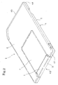
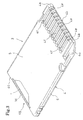
- an adaptor body 4 in which the small card 1 is detachably attached has an external shape for the large card, so that the card adaptor can be connected to a card connector corresponding to the large card.
- the adaptor body 4 comprises: a front end portion 4b which, when inserted into a card connector corresponding to the large card, is positioned in the front side, and which has a tapered portions 4a in the lower portion; and a rear end portion 4c which is positioned in the rear side, and which is configured by a flat face.
- the adaptor body has an edge removal portion on the side of the front end portion 4b and in a left end portion in Fig. 2 .
- a recess 4d which forward and downward opens is formed in the rear face (one principal face) immediately rear of the edge removal portion.
- plural (ten) recesses 4e which forward and downward open, and which are used for protecting external connection terminals are formed in juxtaposition to the recess 4d for preventing erroneous insertion.
- Plural (ten) external connection terminals 4f are disposed in bottom portions of the recesses 4e for protecting the external connection terminals, respectively, so that the external connection terminals 4f are juxtaposed on the rear face (one principal face) on the side of the front end portion 4b.
- a card insertion port 4g through which the small card 1 is to be inserted is formed in a side face on the side of the rear end portion 4c.
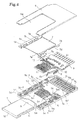
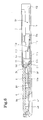
- the card adaptor 3 of the embodiment is configured by: a lower case 5 which has a one-piece structure, and which is made of an insulative synthetic resin; an upper case which has a two-piece structure, and which cooperates with the lower case 5 to constitute the adaptor body 4, i.e., a resin cover 6 made of an insulative synthetic resin, and a metal cover 7 configured by a conductive metal plate for applying countermeasures against electrostatic breakdown and noise; a lock spring 8 which is incorporated in the adaptor body 4, and which is used for holding the small card 1 to the attachment position of the adaptor body 4; plural (two) shield contacts 10 which are integrally held by an insulator 9 made of an insulative synthetic resin to be incorporated in the adaptor body 4, and which are contacted with the metal cover 7 to conductively connect the external connection terminals 4f at the both ends; and plural (nine) card contacting contacts 11 of the invention which are to be contacted with the contact pads 2 of the small card 1 to be conductively
- the lower case 5 is formed by integrating a bottom wall 5a, and a side wall 5b which upstands from front, right, and left side edge portions of the bottom wall 5a with one another.
- Plural upper-case positioning recesses 5c-1 are disposed in the side wall 5b, and plural upper-case welding protrusions 5c-2 are upward projected from an upper portion of the side wall 5b.
- an external-connection terminal attaching portion 5d for positioning and supporting the external connection terminals 4f is formed on the side of the front end portion.
- An insulator attaching portion 5e for positioning and supporting the insulator 9 is formed communicatingly and continuously in rear of the external-connection terminal attaching portion 5d.
- a card insertion space 5f is formed communicatingly and continuously in rear of the insulator attaching portion 5e.
- the rear end side of the card insertion space 5f is communicatingly connected to the card insertion port 4g.
- Plural (ten) external-connection terminal exposing holes 5g which penetrate respectively to the recesses 4e for protecting the external connection terminals are juxtaposed in the bottom face of the external-connection terminal attaching portion 5d.
- a stopper portion 5h which is partly projected from a left edge portion in Fig.
- a contact attaching portion 5j to which one of the shield contacts 10 is to be attached is continuously communicated with the insulator attaching portion 5e.
- a stopper portion 5k which upstans in an island-like manner in the vicinity of the right edge in Fig.
- a contact attaching portion 5m to which the other shield contact 10 is to be attached is continuously communicated with the insulator attaching portion 5e and the card insertion space 5f.
- plural (nine) thin contact housing grooves 5n which correspond respectively to the card contacting contacts 11, and which extend in the anteroposterior direction (in the card insertion and extraction direction) are juxtaposed on the side of the front end portion (inner side).
- a lock-spring attaching portion 5q to which the lock spring 8 is to be attached is formed, and a rear end portion side of the lock-spring attaching portion 5q is communicatingly connected to the card insertion space 5f.
- the resin cover 6 has a cutaway portion 6a the size of which corresponds to the card insertion space 5f, in the rear end side, and is formed into a substantially U-like shape which rearward opens so that an upper portion of the lower case 5 other than the card insertion space 5f is covered by the resin cover 6, and an upper portion of the card insertion space 5f is covered by the metal cover 7, and the metal cover 7 is formed into a rectangular shape in accordance with the shape of the cutaway portion 6a of the resin cover 6, so as to be fittable into the cutaway portion 6a.
- Fixing pieces 7a, 7b which are to overlap with an upper portion of the side wall 5b of the lower case 5 that are on the left and right sides of the card insertion space 5f are integrally continuous to left and right side edge portions of the metal cover 7 while being stepped down through step portions 7c, 7d, respectively.
- plural vertically penetrating engaging holes 7e which are used for positioning the metal cover, and which are to be fitted onto the upper-case welding protrusions 5c-2 of the lower case 5 in the right and left sides of the card insertion space 5f are formed.
- a front end portion of the metal cover 7 is downward bent to be formed as an engaging piece 7f for positioning the metal cover.
- the lock spring 8 is configured by a metal plate spring which is bent into a substantially U-like shape.
- An engaging portion 8a which is formed by bending the metal plate spring along the longitudinal direction into a mountain-like shape is disposed in one end portion of the lock spring 8.
- the card adaptor 3 of the embodiment is assembled in the following manner.
- the lock spring 8 is attached to the lock-spring attaching portion 5q of the lower case 5, and the engaging portion 8a is projected by the elastic force of the lock spring 8 from the communication portion between the rear end portion of the lock-spring attaching portion 5q and the card insertion space 5f, into the card insertion space 5f.
- the insulator 9 is attached to the insulator attaching portion 5e of the lower case 5, and the shield contacts 10 and the card contacting contacts 11 are collectively attached together with all the external connection terminals 4f to the lower case 5.
- the fixing pieces 7a, 7b of the metal cover 7 are superimposed on the upper portion of the side wall 5b of the lower case 5 which is on the right and left sides of the card insertion space 5f, and the upper portion of the card insertion space 5f is covered by the metal cover 7.
- the upper-case welding protrusions 5c-2 of the lower case 5 and the upper-case positioning protrusions of the resin cover 6 in the fitting state are ultrasonic welded to each other to fix the upper case of the two-piece structure configured by the resin cover 6 and the metal cover 7, to the upper portion of the lower case 5, and form the adaptor body 4, thereby completing the assembly.
- the adaptor body 4 has the external shape for the large card, and the card insertion port 4g is formed in the side face on the side of the rear end portion 4c.
- the lock spring 8 is incorporated in the adaptor body 4, and the shield contacts 10 and the card contacting contacts 11 are collectively incorporated together with all the external connection terminals 4f into the adaptor body 4 through the insulator 9.
- the card insertion space 5f which has the front end portion closed by the insulator 9 and the rear end portion that is exposed to the outside by the card insertion port 4g is formed in rear of the insulator 9 in the adaptor body 4.
- the small card 1 can be inserted and attached into the card insertion space 5f through the card insertion port 4g of the adaptor body 4.
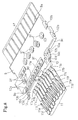
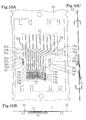
- the contact group disposed in the card adaptor 3 of the embodiment i.e., the two shield contacts 10 and the nine card contacting contacts 11 are molded in a state where, as shown in Fig. 10 , the contacts are integrally coupled to each other in a parallel manner by applying a punching process on a hoop material 12 made of a spring material having superior electrical conductivity.
- the two shield contacts 10 are formed in the right and left ends of the contact group, and the nine card contacting contacts 11 are formed in parallel between the two shield contacts 10.
- an attaching portion 10a for the adaptor body 4 is formed in an intermediate portion, and, also in each of the card contacting contacts 11, an attaching portion 11a for the adaptor body 4 is formed in an intermediate portion.
- the attaching portion 10a of the right shield contact 10 in Fig. 10 is formed integrally with the attaching portion 11a of the right-end card contacting contact 11 in Fig. 10 .
- Plural connecting portions 12a each of which integrally couples adjacent attaching portions together are formed between the attaching portion 10a of the left shield contact 10 in Fig. 10 and the attaching portion 11a of the left-end card contacting contact 11 in Fig. 10 , and between the attaching portions 11a of the card contacting contacts 11.
- Plural connecting portions 12b which integrally connect the two shield contacts 10 and nine card contacting contacts 11 (contact group) that are integrally coupled, to one another with the hoop material (carrier) 12 are formed between the attaching portions 10a of the shield contacts 10 and the hoop material 12.
- the external connection terminal 4f is integrally continuously formed, so that the plural (ten) external connection terminals 4f are arranged in parallel in the one-end side of the two shield contacts 10 and nine card contacting contacts 11 (contact group) that are integrally coupled.
- the right-end external connection terminal 4f in Fig. 10 is an external connection terminal which is common to the right shield contact 10 in Fig. 10 and the right-end card contacting contact 11 in Fig. 10 .
- a bending portion is formed on the other end side, a plate spring piece portion 10c which has a fulcrum portion 10b for supporting the load of the bending portion, in one (basal) side, which extends continuously from the fulcrum portion 10b at an inclination angle in a cantilevered manner so as to be elastically deformable in the thickness direction of the hoop material 12, and which is formed into an L-like section shape, and a contacting portion 10d which is to be in contact with the metal cover 7 is formed in the other side (free-end side) of the plate spring piece portion 10c.
- a first plate spring piece portion 11c In each of the attaching portions 11a of the card contacting contacts 11, a first plate spring piece portion 11c, a second plate spring piece portion 11e, and a contacting portion 11f are formed.
- the other end side extends to between the contacting portions 10d of the shield contacts 10, and a bending portion is formed on the tip end side.
- the first plate spring piece portion has a first fulcrum portion 11b which supports the load of the bending portion, in one (basal) side, and is formed into a shape which continuously extends in a cantilevered manner from the first fulcrum portion 11b to the attaching portion 11a while forming a step, so as to be elastically deformable in the thickness direction of the hoop material 12.
- the second plate spring piece portion 11e is formed by partly cutting and raising the first plate spring piece portion 11c, has in one (basal) side a second fulcrum portion 11d which supports the load of a bending portion formed in the other end side (free-end side) of the first plate spring piece portion 11c, and is formed into a substantially L-like section shape which continuously extends in a cantilevered manner from the second fulcrum portion 11d at an inclination angle in the direction opposite to that of the first plate spring piece portion 11c, so as to be elastically deformable in the thickness direction of the hoop material 12.
- the contacting portion 11f is formed in the other end side (free-end side) of the second plate spring piece portion 11e, and in contact with the corresponding contact pad 2 of the small card 1.
- the attaching portions 10a, 11a of the two shield contacts 10 and nine card contacting contacts 11 (contact group) which are formed by a punching process in the hoop material (carrier) 12 in the state where the contacts are integrally coupled with one another are integrally molded by an insulating synthetic resin by means of insert molding, so that the contacts are integrated with the insulator 9 molded by the mold resin.
- the insulator 9 is formed into a substantially rectangular plate-like shape so as to be fitted to the insulator attaching portion 5e of the lower case 5, and comprises: a front end portion 9a configured by a flat face which is positioned on the side of a rear end portion (the side of a front end portion of the insulator attaching portion 5e) of the external-connection terminal attaching portion 5d of the lower case 5; and a stepped rear end portion having both end portions 9b, 9c of the rear end portion, which are positioned respectively in front end sides of the contact attaching portions 5j, 5m of the lower case 5, and a middle portion 9d of the rear end portion, which is rearward projected from between the both end portions 9b, 9c of the rear end portion, and which is positioned between the stopper portions 5h, 5k of the lower case 5.
- the engaging groove 9e into which the engaging piece 7f of the front end portion of the metal cover 7 is to be fitted is formed in the upper face of the rear end portion on the side of the middle portion 9d.
- plural vertically penetrating holes 9f through which the connecting portions 12a of the shield contacts 10 and the card contacting contacts 11 are exposed from the upper and lower faces of the insulator 9, respectively are formed.
- an electrical connecting component having the contact group disposed in the card adaptor 3 of the embodiment, i.e., the two shield contacts 10 and nine card contacting contacts 11 which are held integrally by the insulator 9 made of the insulative synthetic resin is completed.
- the attaching portions 10a, 11a are embedded in the insulator 9, and the external connection terminals 4f are forward projected in parallel by the same length from the side face of the front end portion 9a of the insulator 9.
- the fulcrum portions 10b of the shield contacts 10, and the plate spring piece portions 10c and contacting portions 10d which precede the fulcrum portions are rearward projected in parallel from the side faces of the both end portions 9b, 9c of the rear end portion of the insulator 9.
- the first fulcrum portions 11b of the card contacting contacts 11, and the first plate spring piece portions 11c, second fulcrum portions 11d, second plate spring piece portions 11e, and contacting portions 11f which precede the fulcrum portions are rearward projected in parallel from the side face of the middle portion 9d of the rear end portion of the insulator 9.
- the insulator 9 is attached to the insulator attaching portion 5e of the lower case 5, thereby allowing the insulator 9 (the attaching portions 10a, 11a of the shield contacts 10 and the card contacting contacts 11) to be positioned and supported by the insulator attaching portion 5e. Furthermore, the external connection terminals 4f of the shield contacts 10 and card contacting contacts 11 which are forward projected in parallel from the side face of the front end portion 9a of the insulator 9 that functions as the side face on the side of the rear end portion of the external-connection terminal attaching portion 5d are positioned and supported above the respective external-connection terminal exposing holes 5g by the external-connection terminal attaching portion 5d.
- the fulcrum portions 10b of the shield contacts 10 which are rearward projected in parallel from the side faces of the both end portions 9b, 9c of the rear end portion of the insulator 9, and the plate spring piece portions 10c and contacting portions 10d which precede the fulcrum portions are housed and placed in the contact attaching portions 5j, 5m.
- the first fulcrum portions 11b of the card contacting contacts 11 which are rearward projected in parallel from the side face on the side of the middle portion 9d of the rear end portion of the insulator 9 that functions as the side face of the front end portion side (inner side) of the card insertion space 5f, and the first plate spring piece portions 11c, second fulcrum portions 11d, second plate spring piece portions 11e, and contacting portions 11f which precede the fulcrum portions are housed and placed in the front end portion side (inner side) of the card insertion space 5f.
- the upper case of the two-piece structure configured by the resin cover 6 and the metal cover 7 is fixed to the upper portion of the lower case 5 to form the adaptor body 4, whereby the upper portions of the insulator 9 and the external connection terminals 4f of the shield contacts 10 and the card contacting contacts 11 are pressed by the resin cover 6 to be fixed into the adaptor body 4.
- the contacting portion 10d of the left shield contact 10 in Fig. 5 is pressed by the fixing piece 7a of the metal cover 7 to be in contact therewith, and the contacting portion 10d of the right shield contact 10 in Fig. 5 is pressed by the metal cover 7 to be in contact therewith, so that the shield contacts 10 cause the metal cover 7 to be always conductively connected to the external connection terminals 4f at the both ends.
- a bottom face 5p in which the depth is inclined so as to be gradually deeper as more advancing from the front end portion side toward the rear end portion side is disposed.
- Each of the first plate spring piece portions 11c of the card contacting contacts 11 is lowered by the bending portion forming the first fulcrum portion 11b disposed in the one (basal) side, from the side face on the side of the middle portion 9d of the rear end portion of the insulator 9 to the corresponding contact housing groove 5n, and, in a state where the first fulcrum portion 11b butts against the front end portion of the bottom face 5p of the contact housing groove 5n, extends substantially horizontally in a cantilevered manner, continuously from the front end portion of the contact housing groove 5n toward the rear end portion side.
- the first plate spring piece portions 11c of the card contacting contacts 11 are placed in the plural contact housing grooves 5n which are juxtaposed on the side of the front end portion (inner side) of the bottom face of the card insertion space 5f, so as to be elastically deformable vertically (in the thickness direction of the small card 1) with using the first fulcrum portions 11b disposed in the one side as a fulcrum, and extend continuously and substantially horizontally in a cantilevered manner from the first fulcrum portions 11b in the direction opposite to the card insertion direction.
- first plate spring piece portions 11c of the card contacting contacts 11 are of the opposed type which is formed into a simple cantilevered shape where the first plate spring piece portions continuously extend from the first fulcrum portions 11b in the one side in the direction opposite to the card insertion direction, therefore, there is no possibility that buckling is caused by insertion of the small card 1 into the card insertion space 5f.
- a pressing portion 5n-2 which prevents the contact from rising, and under which a tapered portion 5n-1 opposed to the tapered portion 11g of the first plate spring piece portion 11c is disposed is formed projectingly toward the front end portion of the contact housing groove 5n, and the rear end portion of the contact housing groove 5n is formed into a pouch-like shape.
- the free-end portion of the first plate spring piece portion 11c of each of the card contacting contacts 11 is housed in the pouch-like portion of the rear end portion of the contact housing groove 5n, and the rising toward the card insertion space 5f is prevented from occurring by the pressing portion 5n-2, while dispersions in the production of the card contacting contacts 11 are absorbed. Therefore, a butt contact with the front end portion 1c of the small card 1 which is inserted into the card insertion space 5f does not occur. Namely, a structure is formed where, in the first plate spring piece portion 11c of each of the card contacting contacts 11, the possibility that buckling is caused by insertion of the small card 1 into the card insertion space 5f is eliminated more surely.
- the second plate spring piece portions 11e of the card contacting contacts 11 have the other end side of the first plate spring piece portion 11c which is positioned on the side of the rear end portion of the contact housing groove 5n, as the second fulcrum portion 11d on one side, extend continuously in a diagonally forward upward direction from the second fulcrum portion 11d in a cantilevered manner, and are projectingly placed in parallel on the side of the front end portion (inner side) of the card insertion space 5f in an inclined state where the front is higher and the rear is lower, so as to be elastically deformable vertically (in the thickness direction of the small card 1) with using the second fulcrum portions 11d as a fulcrum, thereby causing the contacting portion 11f disposed on the other side (free-end side) to be contacted with the corresponding contact pad 2 of the small card 1 inserted into the card insertion space 5f.
- each of the second plate spring piece portions 11e which are placed in the card insertion space 5f, and which are to be contacted with the contact pads 2 of the small card 1 inserted into the card insertion space 5f is configured as the unopposed type in which the portion continuously extends at an inclination angle in a cantilevered manner from the second fulcrum portion 11d disposed in one side, in the card insertion direction (forward direction). Therefore, there is no possibility that buckling is caused by insertion of the small card 1 into the card insertion space 5f.
- the small card 1 When the small card 1 is to be attached to the thus configured card adaptor 3 of the embodiment, the small card 1 is normally inserted from the front end portion 1c into the card insertion space 5f through the card insertion port 4g of the adaptor body 4 in a state where the rear face (one principal face) of the small card 1 where the contact pads 2 are juxtaposed is positioned on the side of the lower case 5 of the adaptor body 4.
- the engaging portion 8a of the lock spring 8 which is attached to the lock-spring attaching portion 5q is projected in one side edge portion of the card insertion space 5f.
- the small card 1 outward presses the engaging portion 8a of the lock spring 8 with the side edge portion on the side of the step portion 1f in which the recess 1i is formed, and, in a state where, while flexurally deforming the lock spring 8 toward the outside, the engaging portion 8a is retracted in the lock-spring attaching portion 5q, the small card is inserted toward the front end portion side (inner side) of the card insertion space 5f.
- the front end portion 1c of the small card 1 butts against the stopper portions 5h, 5k formed in the lower case 5 of the adaptor body 4.
- the insertion of the small card 1 is restricted, the engaging portion 8a of the lock spring 8 is opposed to the recess 1i of the small card 1, and the engaging portion 8a is returned by the elastic force of the lock spring 8 to be engaged with the recess 1i of the small card 1.
- the small card 1 is completely inserted into the card insertion space 5f of the adaptor body 4, and accidental drop-off of the small card 1 is prevented by the lock spring 8 from occurring.
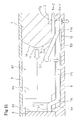
- the first plate spring piece portions 11c of the card contacting contacts 11 extend continuously and substantially horizontally in a cantilevered manner from the first fulcrum portions 11b in the direction opposite to the card insertion direction, in the plural contact housing grooves 5n which are juxtaposed on the side of the front end portion (inner side) of the bottom face of the card insertion space 5f, in the state where the first fulcrum portions 11b disposed in the one (basal) side butt against the front end portions of the bottom faces 5p of the contact housing grooves 5n, and the gaps 13 which are gradually increased as more advancing toward the other end sides (free-end sides) of the first plate spring piece portions 11c are formed between the first plate spring piece portions 11c preceding the first fulcrum portions 11b and the bottom faces 5p of the contact housing grooves 5n.
- the second plate spring piece portions 11e having the other end sides of the first plate spring piece portions 11c which are positioned on the side of the rear end portions of the contact housing grooves 5n, as the second fulcrum portions 11d on one side extend continuously in a diagonally forward upward direction from the second fulcrum portions 11d in a cantilevered manner, and are projectingly placed in parallel on the side of the front end portion (inner side) of the card insertion space 5f in an inclined state where the front is higher and the rear is lower. As shown in Fig.
- the lower side of the front end portion 1c of the small card 1 is contacted with the inclined surfaces of the second plate spring piece portions 11e of the card contacting contacts 11, and then the small card 1 slides to press down the second plate spring piece portions. Therefore, the first plate spring piece portions 11c of the card contacting contacts 11 are downward flexurally deformed with setting the first fulcrum portions 11b butting against the front end portions of the bottom faces 5p of the contact housing grooves 5n, as fulcrums, and butt against the bottom faces 5p of the contact housing grooves 5n.
- the lower side of the front end portion 1c of the small card 1 passes over the contacting portions 11f of the card contacting contacts 11, the small card 1 overrides the flexurally deformed first and second plate spring piece portions 11c, 11e of the card contacting contacts 11, and the contacting portions 11f of the card contacting contacts 11 are pressed and contacted from the lower side against the contact pads 2 juxtaposed on the rear face (one principal face) of the small card 1, by the elastic forces of the first and second plate spring piece portions 11c, 11e.
- the contact pads 2 of the small card 1 which is completely inserted into the card insertion space 5f of the adaptor body 4 are conductively connected to the corresponding external connection terminals 4f through the card contacting contacts 11.
- the second plate spring piece portions 11e are returned to their original shapes by their elastic forces with using the second fulcrum portions 11d as fulcrums, and then the first plate spring piece portions 11c are returned to their original shapes, so that the first and second plate spring piece portions 11c, 11e of the card contacting contacts 11 are returned to the free state shown in Fig. 11 .
- the external connection terminals 4f of the adaptor body 4 are contacted with plural contacts juxtaposed in a card insertion space of the card connector, respectively, so that the small card 1 is electrically connected to an electronic apparatus corresponding to the large card (an electronic apparatus in which the card connector corresponding to the large card is mounted on a printed circuit board) such as a portable telephone, to allow signals to be transmitted between the small card and the electronic apparatus.
- an electronic apparatus corresponding to the large card an electronic apparatus in which the card connector corresponding to the large card is mounted on a printed circuit board
- a portable telephone to allow signals to be transmitted between the small card and the electronic apparatus.
- the small card 1 can be used in the electronic apparatus corresponding to the large card.
- the card adaptor 3 of the embodiment comprises the card contacting contacts 11 each of which is to be placed in the card insertion space 5f and contacted with the contact pad 2 which is disposed on one principal face of the card 1, wherein the first plate spring piece portion 11c having the first fulcrum portion 11b in one side extends in a cantilevered manner from the first fulcrum portion 11b in the direction opposite to the card insertion direction so as to be elastically deformable in the thickness direction of the card, the second plate spring piece portion 11e having in one side the second fulcrum portion 11d which is the other side of the first plate spring piece portion 11c is formed in a shape where the second plate spring piece portion extends at an inclination angle in a cantilevered manner from the second fulcrum portion 11d in the card insertion direction so as to be elastically deformable in the card thickness direction, and the other side of the second plate spring piece portion 11e is to be contacted with the contact pad 2 of the card 1. Furthermore, the case members 5, 6,
- the plate spring piece portion (second plate spring piece portion 11e) which is to be contacted with the contact pad 2 of the card 1 is configured as the unopposed type in which the portion extends at an inclination angle in a cantilevered manner from the fulcrum portion (second fulcrum portion 11d) in the card insertion direction (forward direction). Therefore, the possibility that buckling is caused by insertion of the card 1 can be eliminated, and the contact pressure can be increased or decreased in accordance with increase or decrease of the displacement amount of the contact 11.
- a sufficient contact pressure can be ensured even when the spring constant of the contact 11 is not increased, the range of a displacement amount where an adequate contact pressure can be obtained is not narrowed (see Fig. 18 ), and it is not required to strictly manage the position of the contacting portion 11f to suppress dispersions.
- a stable contact pressure of the contact 11 can be easily ensured.
- a stress can be dispersed to two portions (the first fulcrum portion 11b of the first plate spring piece portion 11c and the second fulcrum portion 11d of the second plate spring piece portion 11e), and in addition a generated stress can be suppressed to a low level by not increasing the spring constant. This stress relaxation can prolong the life period of the contact 11. Therefore, a long life period of the contact 11 can be easily ensured.
- the second plate spring piece portion 11e may be formed in a shape where it is folded back from the other side of the first plate spring piece portion 11c.
- the second plate spring piece portion 11e may be formed by partly cutting and raising the first plate spring piece portion 11c, thereby allowing the second plate spring piece portion 11e to directly extend at an inclination angle in a cantilevered manner from the other side of the first plate spring piece portion 11c in the card insertion direction (forward direction), without passing through a folded back portion (radius of curvature). Therefore, a larger displacement amount of the contact 11 can be obtained, and a stable contact pressure of the contact 11 can be ensured more easily.
- the two external connection terminals 4f (the two shield contacts 10 and the right-end card contacting contact 11 in Fig. 5 ) in the right and left ends in Fig. 5 are used for grounding, and the two external connection terminals 4f are individually separated.
- the two external connection terminals 4f may be continuously integrally molded to be conductively connected (short-circuited) to each other, or conductively connected (short-circuited) to each other by using a conductive member which is configured as a separate component.
- the third card 21 comprises: a front end portion 21b which, when the third card 21 is inserted into a card adaptor for connecting with a card connector corresponding to a larger card or the card connector of the embodiment, is positioned in the front side, and which has a tapered portion 21a in the lower portion; and a rear end portion 21c which is positioned in the rear side, and which is configured by a flat face.
- a cutaway portion 21d for preventing erroneous insertion in an inverted front and rear or surface and rear face relationship into a card adaptor for connecting the third card 21 with a card connector corresponding to a larger card or the card connector of the embodiment, from occurring is disposed on the side of the front end portion 21b of a right side edge portion in Fig. 13A .
- a cutaway portion 21e for, when the third card 21 is inserted into a card adaptor for connecting with a card connector corresponding to a larger card or the card connector of the embodiment, holding the third card 21 to an attachment position of the card adaptor or the card connector is formed on the side of the rear end portion 21c with respect to the cutaway portion 21d for preventing erroneous insertion.
- Plural (eight) contact pads 22 for external connection are juxtaposedly arranged on the rear face (one principal face) on the side of the front end portion 21d.
- the card connector 23 of the embodiment is configured by: a connector housing 25 comprising a front end portion 25a positioned in a card insertion port disposed in a case of an electronic apparatus, and a rear end portion 25b opposite to the portion, and having a box-like shape where a card insertion port 24 through which the third card 21 is inserted from the front end portion 21b while downward directing the rear face on which the contact pads 22 are juxtaposed opens in a side face on the side of the front end portion 25a; plural (eight) card contacting contacts 26 of the invention which are incorporated in the connector housing 25, and which are contacted with the contact pads 22 of the third card 21, respectively, so that the card is electrically connected to a printed circuit board of the electronic apparatus; a card recognition switch (not shown) which is incorporated in the connector housing 25, and which is formed by a pair of metal pieces for electrically detecting attachment of the third card 21 on the side of the electronic apparatus; and a push/push type card extraction mechanism 27 which
- the internal space on the inner side (front side) of the card insertion port 24 functions as a card insertion space 28 where the card contacting contacts 26 and the card recognition switch are placed, and the internal space on the right side of the card insertion space 28 functions as a space for placing the card extraction mechanism 27.
- the connector housing 25 is configured by: a lower case 29 to which conductive members such as the card contacting contacts 26 and the pair of metal pieces for the card recognition switch are attached, and which is made of an insulative synthetic resin; and an upper case 30 which is attached from the upper side to the lower case 29 to apply countermeasures against electrostatic breakdown and noise, and which is formed by punching and bending a metal plate.
- the lower case 29 is formed by integrating a housing bottom wall 29a, a housing right side wall 29b, a housing rear side wall 29c, and a housing front wall 29d which is on the right side of the card insertion port 24.
- Positioning engaging portions 29e and plural fixation engaging portions 29f which are to coupled with the upper case 30 are projected in outer side directions from the left end face of the housing bottom wall 29a and the outer face of the housing right side wall 29b.
- plural (eight) thin contact housing grooves 29g which correspond respectively to the card contacting contacts 26, and which extend in the anteroposterior direction (in the card insertion and extraction direction) are juxtaposed on the side of the front end portion (inner side).
- Front and rear stopper portions 29h, 29i which receive a slide member of the card extraction mechanism 27 are disposed in front and rear end portions of the space for placing the card extraction mechanism 27, respectively.
- a bearing portion 29j for supporting a cam pin of the card extraction mechanism 27 is disposed in the thickness of the front stopper portion 29h.
- a return-side stopper portion 29k which is engaged with an engaging portion of a lock spring of the card extraction mechanism 27 which is used for the third card 21 is disposed in an end portion of the housing front wall 29d.
- the rear end portion side is passed through the housing rear side wall 29c, and opens in the outer face, and a bottom face in which the depth is inclined so as to be gradually deeper as more advancing from the rear end portion side toward the front end portion side is disposed.
- the upper case 30 is configured by integrally forming a housing top plate 30a, a housing left side wall 30b, and a housing right side wall cover 30c which covers the outer face of the housing right side wall 29b of the lower case 29.
- a housing left side wall 30b and the housing right side wall cover 30c On the housing left side wall 30b and the housing right side wall cover 30c, positioning engaging recesses 30d into which the positioning engaging portions 29e of the lower case 29 are to be fitted, and plural fixation engaging holes 30e into which the fixation engaging portions 29f of the lower case 29 are to be fitted are disposed.
- terminal portions 30f which are used for mounting the connector, and which are formed by bending front and rear end portions of the lower edge so as to be projected substantially horizontally toward the outer side are disposed.
- a plate spring piece 30g which is provided with elasticity for always downward pressing the cam pin of the card extraction mechanism 27 is formed in a cantilevered manner by cutting and raising.
- the card contacting contacts 26 are molded in a state where they are integrally coupled to each other in a parallel manner by applying a punching process on a hoop material made of a spring material having superior electrical conductivity.
- an attaching portion 26a for the lower case 29 is formed in the rear end portion side.
- an external connection terminal 26c which extends substantially horizontally in a rearward direction is formed in a rear end portion side so as to be continuous from a position which is stepped down through a bent portion 26b.
- a first plate spring piece portion 26e which has a first fulcrum portion 26d for supporting the load of the front end portion side of the attaching portion 26a, in one (basal) side, and which is formed into a shape which continuously forward extends in a cantilevered manner from the first fulcrum portion 26d, so as to be elastically deformable in the thickness direction of the hoop material.
- a second plate spring piece portion 26g is formed by partly cutting and raising the first plate spring piece portion 26e, has in one (basal) side a second fulcrum portion 26f which supports the load of a bending portion formed in the other end side (free-end side) of the first plate spring piece portion 26e, and is formed into a substantially L-like section shape which continuously extends at an inclination angle in a cantilevered manner from the second fulcrum portion 26f in the (rearward) direction opposite to that of the first plate spring piece portion 26e, so as to be elastically deformable in the thickness direction of the hoop material.
- a contacting portion 26h is formed in the other end side (free-end side) of the second plate spring piece portion 26g, and in contact with the corresponding contact pad 22 of the third card 21.
- the external connection terminals 26c of the card contacting contacts 26 are integrally coupled with one another by connecting portions, and the connecting portions are integrally coupled with the hoop material (carrier) by plural connecting pieces, so that the eight card contacting contacts 26 are integrally coupled with the hoop material in a parallel manner.
- the eight card contacting contacts 26 (contact group) which are molded by a punching process on the hoop material (carrier) in the state where they are integrally coupled to one another as described above are separated from the hoop material (carrier) by cutting off the connecting pieces.
- the other ends (free end sides) of the first plate spring piece portions 26e of the card contacting contacts 26 are inserted from the rear side of the lower case 29 into the respective contact housing grooves 29g, and the attaching portions 26a of the card contacting contacts 26 are pressingly inserted and fixed to the housing rear side wall 29c of the case 29. Thereafter, the connecting portions are cut off, whereby the eight card contacting contacts 26 in a state where they are individually separated are attached to the lower case 29.
- the external connection terminals 26c are lowered through the bent portions 26b to a lower portion of the lower case 29, and then rearward projected in parallel from the outer face of the housing rear side wall 29c.
- each of the first plate spring piece portions 26e of the card contacting contacts 26 extends substantially horizontally in a cantilevered manner, continuously from the rear end portion toward the front end portion side in the contact housing groove 29g.
- the first plate spring piece portions 26e of the card contacting contacts 26 are placed in the plural contact housing grooves 29g which are juxtaposed on the side of the rear end portion (inner side) of the bottom face of the card insertion space 28, so as to be elastically deformable vertically (in the thickness direction of the third card 21) with using the first fulcrum portions 26d disposed in the one side as a fulcrum, and extend substantially horizontally in a cantilevered manner from the first fulcrum portions 26d in the direction opposite to the card insertion direction.
- first plate spring piece portions 26e of the card contacting contacts 26 are of the opposed type which is formed into a simple cantilevered shape where the first plate spring piece portions continuously extend from the first fulcrum portions 26d disposed in the one side in the direction opposite to the card insertion direction, therefore, there is no possibility that buckling is caused by insertion of the third card 21 into the card insertion space 28.
- first plate spring piece portion 26e of each of the card contacting contacts 26 an edge portion of the upper side of the free end is chamfered to form a tapered portion.
- a pressing portion which prevents the contact from rising, and under which a tapered portion opposed to the tapered portion of the first plate spring piece portion 26e is disposed is formed projectingly toward the rear end portion of the contact housing groove 29g, and the front end portion of the contact housing groove 29g is formed into a pouch-like shape.
- the free-end portion of the first plate spring piece portion 26e of each of the card contacting contacts 26 is housed in the pouch-like portion of the front end portion of the contact housing groove 29g, and the rising toward the card insertion space 28 is prevented from occurring by the pressing portion, while dispersions in the production of the card contacting contacts 26 are absorbed. Therefore, a butt contact with the front end portion 21b of the third card 21 which is inserted into the card insertion space 28 does not occur. Namely, a structure is formed where, in the first plate spring piece portion 26e of each of the card contacting contacts 26, the possibility that buckling is caused by insertion of the third card 21 into the card insertion space 28 is eliminated more surely.
- the second plate spring piece portions 26g of the card contacting contacts 26 have the other end side of the first plate spring piece portion 26e which is positioned on the side of the front end portion of the contact housing groove 29g, as the second fulcrum portion 26f on one side, extend continuously in a diagonally rearward upward direction from the second fulcrum portion 26f in a cantilevered manner, and are projectingly placed in parallel on the side of the rear end portion (inner side) of the card insertion space 28 in an inclined state where the front is lower and the rear is higher, so as to be elastically deformable vertically (in the thickness direction of the third card 21) with using the second fulcrum portions 26f as a fulcrum, thereby causing the contacting portion 26h disposed on the other side (free-end side) to be contacted with the corresponding contact pad 22 of the third card 21 inserted into the card insertion space 28.
- each of the second plate spring piece portions 26g which are placed in the card insertion space 28, and which are to be contacted with the contact pads 22 of the third card 21 inserted into the card insertion space 28 is configured as the unopposed type in which the portion continuously extends at an inclination angle in a cantilevered manner from the second fulcrum portion 26f disposed in one side in the card insertion direction (forward direction). Therefore, there is no possibility that buckling is caused by insertion of the third card 21 into the card insertion space 28.
- the push/push type card extraction mechanism 27 is configured by: a slide member 31; a coil spring 32 which is an urging member for the slide member 31; a position holding mechanism which is used for the slide member 31, and which is formed by a heart-shaped cam groove 33 and a cam pin 34; and a lock spring 35 which causes the third card 21 to be engaged with the slide member 31.
- the slide member 31 is made of an insulative synthetic resin, and placed in the space for placing the card ejection mechanism 27 in the housing 25 so as to be reciprocable in the anteroposterior direction (in the card insertion and extraction direction) along the housing right side wall 29b between the front and rear stopper portions 29h, 29i.
- an overhang portion 31a which is projected to the left side of the card insertion space 28, and which, in the card insertion, is fitted into the erroneous insertion preventing cutaway portion 21d of the third card 21, an operating portion 31b which, in order that the slide member 31 is pushed toward the inner side by the third card 21, is projected from a rear portion of the overhang portion 31a into the card insertion space 28 so as to butt against the front end portion 21b of the third card 21, the heart-shaped cam groove 33 of the position holding mechanism, and a slit groove 31c for attaching the lock spring 35 are integrally formed.
- the coil spring 32 is placed between the slide member 31 and the rear stopper portion 29i, and always urges the slide member 31 toward the front side (card extraction direction).
- the cam pin 34 of the positioning mechanism is configured by a thin round metal bar which is bent in a U-like shape, and moved in the cam groove 33 in accordance with the movement of the slide member 31 while one end of the cam pin is substantially perpendicularly contacted with the bottom of the cam groove 33 formed in the slide member 31, and the other end is rotatably supported by the bearing portion 29j disposed in the lower case 29.
- the cam pin 34 is always downward pressed by the plate spring piece 30g disposed on the upper case 30, one end of the cam pin is substantially perpendicularly pressed against the cam groove 33, and the other end is pushed into the bearing portion 29j.
- the lock spring 35 is configured by a metal plate spring. In one end portion of the spring, an engaging portion 35a which is formed by bending the metal plate spring into a mountain-like shape along the length direction is disposed.
- an engaging portion 35a which is formed by bending the metal plate spring into a mountain-like shape along the length direction is disposed.
- the thus configured card connector 23 of the embodiment can be used with being surface-mounted on a printed circuit board incorporated in a case of an electronic apparatus such as a portable telephone, while the terminal portions 30f of the upper case 30, the external connection terminals 26c of the card contacting contacts 26, and the external connection terminals of the pair of metal pieces forming the card recognition switch are mechanically fixed and electrically connected by soldering the printed circuit board.
- the third card 21 When the third card 21 is to be attached to the thus configured card connector 23 of the embodiment, the third card 21 is normally inserted from the front end portion 21b into the card insertion space 28 through the card insertion port 24 of the connector housing 25 in a state where the rear face (one principal face) of the third card 21 where the contact pads 22 are juxtaposed is positioned on the side of the lower case 29. Then, the third card 21 is fitted between the housing left side wall 30b and the slide member 31 while the overhang portion 31a of the slide member 31 is fitted into the erroneous insertion preventing cutaway portion 21d of the third card 21, and the front end portion 21b of the third card 21 butts against the operating portion 31b of the slide member 31.
- the engaging portion 35a is fitted into the lock cutaway portion 21e of the third card 21 by the elastic force of the lock spring 35 with being opposed to the lock cutaway portion 21e of the third card 21.
- the third card 21 and the slide member 31 are engaged and coupled with each other in the card insertion and extraction direction.
- the front end portion 21b of the third card 21 pushes rearward the operating portion 31b of the slide member 31 to rearward press the slide member 31 against the elastic force of the coil spring 32, and the slide member 31 stops at the extreme pressed position where the slide member butts against the rear stopper portion 29i.
- the cam pin 34 passes through a forward path 33b from a starting portion 33a of the cam groove 33, and is introduced into and engaged with an engaging portion 33c which is opposite to the starting portion 33a.
- the forward movement of the slide member 31 is restricted. As shown in Fig. 17 , this causes the slide member 31 to be held to the card attaching position which is slightly in front of the extreme pressed position, and the third card 21 which is engaged and coupled with the slide member 31 in the card insertion and extraction direction is held to the card attaching position and attached to the connector housing 25.
- the first plate spring piece portions 26e of the card contacting contacts 26 extend continuously and substantially horizontally in a cantilevered manner from the first fulcrum portions 26d in the direction opposite to the card insertion direction, in the plural contact housing grooves 29g which are juxtaposed on the side of the rear end portion (inner side) of the bottom face of the card insertion space 28, in the state where the first fulcrum portions 26d disposed in the one (basal) side butt against the rear end portions of the bottom faces of the contact housing grooves 29g, and the gaps which are gradually increased as more advancing toward the other end sides (free-end sides) of the first plate spring piece portions 26e are formed between the first plate spring piece portions 26e preceding the first fulcrum portions 26d and the bottom faces of the contact housing grooves 29g.
- the first plate spring piece portions 26e of the card contacting contacts 26 are downward flexurally deformed with setting the first fulcrum portions 26d butting against the rear end portions of the bottom faces of the contact housing grooves 29g, as fulcrums, and butt against the bottom faces of the contact housing grooves 29g.
- the second plate spring piece portions 26g of the card contacting contacts 26 are downward flexurally deformed with setting the second fulcrum portions 26f butting against the front end portions of the bottom faces of the contact housing grooves 29g, as fulcrums.
- the third card 21 overrides the flexurally deformed first and second plate spring piece portions 26e, 26g of the card contacting contacts 26, and the contacting portions 26h of the card contacting contacts 26 are pressed and contacted from the lower side against the contact pads 22 juxtaposed on the rear face (one principal face) of the third card 21, by the elastic forces of the first and second plate spring piece portions 26e, 26g.
- the contact pads 22 of the third card 21 attached on the connector housing 25 are electrically connected by the card contacting contacts 26 to an electronic apparatus (an electronic apparatus in which the card connector 23 of the embodiment is mounted on a printed circuit board) such as a portable telephone, to allow signals to be transmitted between the card and the electronic apparatus.
- an electronic apparatus an electronic apparatus in which the card connector 23 of the embodiment is mounted on a printed circuit board
- the displacing operations of the first and second plate spring piece portions 26e, 26g of the above-described card contacting contacts 26 in the card connector 23 of the embodiment are identical with those of the first and second plate spring piece portions 11c, 11e of the card contacting contacts 11 in the card adaptor 3 shown in Figs. 11 and 12 . Therefore, their illustration is omitted.
- the slide member 31 When the pressing force on the slide member 31 by the third card 21 is thereafter eliminated to release the slide member 31, the slide member 31 is forward pushed back from the extreme pressed position to return to the initial position while the front end portion 21b of the third card 21 is forward pushed by the operating portion 31b by means of the elastic force of the coil spring 32, and the third card 21 is extracted.
- the cam pin 34 passes through the return path 33d and returns to the starting portion 33a of the cam groove 33.
- the rear end portion 21c of the card 21 projected from the card insertion port 24 to the outside of the housing 25 is nipped by fingers and pulled, the engaging portion 35a of the lock spring 35 slides over the side face of the lock cutaway portion 21e of the third card 21, and overrides the side edge portion between the lock cutaway portion 21e of the third card 21 and the erroneous insertion preventing cutaway portion 21d, while involving deflection toward the outside (right side) of the lock spring 35, and the engaging and coupling of the third card 21 and the slide member 31 in the card insertion and extraction direction is cancelled.
- the third card 21 can be pulled out from the connector housing 25 through the card insertion port 24. After the third card 21 is pulled out, the state shown in Fig. 15 is attained.
- the card connector 23 of the embodiment comprises the card contacting contacts 26 each of which is to be placed in the card insertion space 28 and contacted with the contact pad 22 which is disposed on one principal face of the card 21, wherein the first plate spring piece portion 26e having the first fulcrum portion 26d in one side extends in a cantilevered manner from the first fulcrum portion 26d in the direction opposite to the card insertion direction so as to be elastically deformable in the thickness direction of the card, the second plate spring piece portion 26g having in one side the second fulcrum portion 26f which is the other side of the first plate spring piece portion 26e is formed in a shape where the second plate spring piece portion extends at an inclination angle in a cantilevered manner from the second fulcrum portion 26f in the card insertion direction so as to be elastically deformable in the card thickness direction, and the other side of the second plate spring piece portion 26g is to be contacted with the contact pad 22 of the card 21.
- the case member for forming the card insertion space 28 constitutes the connector housing 25 having a box-like shape configured by the insulative lower case 29 to which the card contacting contacts 26 are attached, and the conductive upper case 30 which is coveringly attached to the lower case 29.
- the plate spring piece portion (second plate spring piece portion 26g) which is to be contacted with the contact pad 22 of the card 21 is configured as the unopposed type in which the portion extends at an inclination angle in a cantilevered manner from the fulcrum portion (second fulcrum portion 26f) in the card insertion direction (forward direction). Therefore, the possibility that buckling is caused by insertion of the card 21 can be eliminated, and the contact pressure can be increased or decreased in accordance with increase or decrease of the displacement amount of the contact 26.
- a sufficient contact pressure can be ensured even when the spring constant of the contact 26 is not increased, the range of a displacement amount where an adequate contact pressure can be obtained is not narrowed (see Fig. 18 ), and it is not required to strictly manage the position of the contacting portion 26h to suppress dispersions.
- a stable contact pressure of the contact 26 can be easily ensured.
- a stress can be dispersed to two portions (the first fulcrum portion 26d of the first plate spring piece portion 26e and the second fulcrum portion 26f of the second plate spring piece portion 26g), and in addition a generated stress can be suppressed to a low level by not increasing the spring constant. This stress relaxation can prolong the life period of the contact 26. Therefore, a long life period of the contact 26 can be easily ensured.
- the second plate spring piece portion 26g may be formed in a shape where it is folded back from the other side of the first plate spring piece portion 26e.
- the second plate spring piece portion 26g may be formed by partly cutting and raising the first plate spring piece portion 26e, thereby allowing the second plate spring piece portion 26g to directly extend at an inclination angle in a cantilevered manner from the other side of the first plate spring piece portion 26e in the card insertion direction (forward direction), without passing through a folded back portion (radius of curvature). Therefore, a larger displacement amount of the contact 26 can be obtained, and a stable contact pressure of the contact 26 can be ensured more easily.
Landscapes
- Coupling Device And Connection With Printed Circuit (AREA)
Abstract
Description
- The present invention relates to a contact which is to be contacted with a contact pad disposed on one principal face of a card such as a memory card, and also to a card adaptor and card connector having such a contact.
- There are a card connector for connecting a memory card to an electronic apparatus, and a card adaptor for connecting a memory card according to another standard in which the size is more reduced than a certain standard in which the size reduction is not specified, to another card connector corresponding to another memory card according the certain standard. In a card insertion space of the card connector or the card adaptor, contacts (contact members) each configured by a metal plate spring having superior electrical conductivity are disposed so as to be contacted respectively with plural contact pads which are juxtaposedly arranged on one principal face of a card.
- A conventional contact has a fulcrum portion which supports a load, in one side, and is formed into a simple cantilevered shape which extends from the fulcrum portion at a certain inclination angle, in a direction that is opposite to the card insertion direction. The other side of the contact is pressed against a contact pad of a card to attain a contact state.
- Such a conventional contact, and a conventional card adaptor and card connector having it are disclosed in, for example,
Japanese Patent Application Laying-Open Nos. 2005-150000 2006-269102 - The situation of a card contacting contact is as follows. Because of miniaturization and thinning of an electronic apparatus typified by a portable telephone, and those of a card itself, also a contact is miniaturized, and the displacement amount of a contact is further suppressed. Accordingly, it is difficult to ensure a sufficient contact pressure (a contact pressure is proportional to a contact displacement amount in accordance with Hook's law).
- A conventional contact is of the opposed type which is formed into a simple cantilevered shape. There is the possibility that buckling is caused by card insertion. The contact displacement amount cannot be increased more than a certain level. In order to ensure a sufficient contact pressure, consequently, there is no choice but to increase the spring constant.
- As apparent from the relationship of a contact pressure F (N) of a contact and a displacement amount x (mm) shown in
Fig. 18 , when the spring constant k of a contact is increased, however, the range of a displacement amount where an adequate contact pressure can be obtained is narrowed (B < A). Therefore, a stable contact pressure cannot be obtained unless the position of a contacting portion is strictly managed to suppress dispersions, and it is difficult to ensure a stable contact pressure. Structurally, a stress is concentrated to one portion (one fulcrum portion), and a generated stress is made larger in accordance with an increase of the spring constant k. Therefore, the life period is shortened. - The problem which is to be solved by the invention is that the conventional contact shape cannot ensure a stable contact pressure and a long life period.
- In order to solve the problem, the contact of the invention is a contact which is to be placed in a card insertion space and contacted with a contact pad which is disposed on one principal face of a card, wherein a first plate spring piece portion having a first fulcrum portion in one side extends in a cantilevered manner from the first fulcrum portion in a direction opposite to a card insertion direction so as to be elastically deformable in a thickness direction of the card, a second plate spring piece portion having in one side a second fulcrum portion which is another side of the first plate spring piece portion is formed in a shape where the second plate spring piece portion extends at an inclination angle in a cantilevered manner from the second fulcrum portion in the card insertion direction so as to be elastically deformable in the card thickness direction, and another side of the second plate spring piece portion is to be contacted with the contact pad of the card. The plate spring piece portion (second plate spring piece portion) which is to be contacted with the contact pad of the card is configured as the unopposed type in which the portion extends at an inclination angle in a cantilevered manner from the fulcrum portion (second fulcrum portion) in the card insertion direction (forward direction). Therefore, the possibility that buckling is caused by card insertion can be eliminated, and the contact pressure can be increased or decreased in accordance with increase or decrease of a displacement amount of the contact. Consequently, a sufficient contact pressure can be ensured even when the spring constant of the contact is not increased, the range of a displacement amount where an adequate contact pressure can be obtained is not narrowed, and it is not required to strictly manage the position of a contacting portion to suppress dispersions. As a result, a stable contact pressure of the contact can be easily ensured. Structurally, a stress can be dispersed to two portions (the first fulcrum portion of the first plate spring piece portion and the second fulcrum portion of the second plate spring piece portion), and in addition a generated stress can be suppressed to a low level by not increasing the spring constant. This stress relaxation can prolong the life period of the contact. Therefore, a long life period of the contact can be easily ensured.
- In the contact of the invention, the second plate spring piece portion may be formed in a shape where it is folded back from the other side of the first plate spring piece portion, or preferably the second plate spring piece portion may be formed by partly cutting and raising the first plate spring piece portion. In this configuration, the second plate spring piece portion can directly extend at an inclination angle in a cantilevered manner from the other side of the first plate spring piece portion in the card insertion direction (forward direction), without passing through a folded back portion (radius of curvature). Therefore, a larger displacement amount of the contact can be obtained, and a stable contact pressure of the contact can be ensured more easily. Preferably, an attaching portion to a case member for forming a card insertion space may be continuously integrated with the first fulcrum portion of the first plate spring piece portion. Preferably, an external connection terminal may be continuously integrated with the attaching portion.
- The card adaptor of the invention comprises the above-described contact of the invention, and the case member for forming the card insertion space constitutes an adaptor body having an external shape for another card which is larger than the card that is to be inserted into the card insertion space. Therefore, a stable contact pressure and a long life period can be easily ensured in the contact for card contact disposed in the card adaptor.
- The card connector of the invention comprises the above-described contact of the invention, and the case member for forming the card insertion space constitutes a connector housing having a box-like shape configured by an insulative lower case to which the contact is attached, and a conductive upper case which is coveringly attached to the lower case. Therefore, a stable contact pressure and a long life period can be easily ensured in the contact for card contact disposed in the card connector.
-
-
Fig. 1A is a front view showing a card to be used with a card adaptor of the embodiment of the invention,Fig. 1B is a side view, andFig. 1C is a rear view; -
Fig. 2 is a perspective view showing the appearance of the front side of the card adaptor; -
Fig. 3 is a perspective view showing the appearance of the rear side of the card adaptor; -
Fig. 4 is a perspective view showing a disassembled state of the card adaptor; -
Fig. 5 is a perspective view showing an internal structure of the card adaptor; -
Fig. 6 is a section view showing the internal structure of the card adaptor; -
Fig. 7 is a section view showing an internal structure of a card attachment state of the card adaptor; -
Fig. 8 is a perspective view showing the appearance of a contact group disposed in the card adaptor; -
Fig. 9A is a plan view showing the contact group disposed in the card adaptor,Fig. 9B is a front view, andFig. 9C is a side view; -
Fig. 10A is a plan view showing a hoop material in which the contact group disposed in the card adaptor is molded,Fig. 10B is a section view, andFig. 10C is a side view; -
Fig. 11 is a partial enlarged section view showing a state where a contact contacting portion disposed in the card adaptor has not yet been displaced. -
Fig. 12 is a partial enlarged section view showing a state where the contact contacting portion disposed in the card adaptor has been displaced. -
Fig. 13A is a front view showing a card to be used with a card connector of the embodiment of the invention,Fig. 13B is a side view, andFig. 13C is a rear view; -
Fig. 14 is a perspective view showing the appearance of the card connector; -
Fig. 15 is a section view showing the internal structure of the card connector; -
Fig. 16 is a perspective view showing the appearance of a contact disposed in the card connector; -
Fig. 17 is a plan view showing an internal structure of a card attachment state of the card connector; and -
Fig. 18 is a graph showing the relationship of a contact pressure F (N) of a contact and a displacement amount x (mm). - Hereinafter, an embodiment of the connector and card adaptor having it according to the invention will be described with reference to
Figs. 1 to 12 . The embodiment is a card adaptor for connecting a memory card according to a certain standard in which size reduction is not specified, for example, Memory Stick PRO Duo (a trademark of Sony Corporation) (hereinafter, referred to as "large card"), to a card connector corresponding to another memory card according to another standard in which the size is more reduced than the certain standard, for example, Memory Stick Micro (a trademark of Sony Corporation) (hereinafter, referred to as "small card"). - As shown in
Fig. 1 , thesmall card 1 comprises: afront end portion 1c which, when the card is inserted into a card connector corresponding to thesmall card 1 or the card adaptor of the embodiment, is positioned in the front side, and which has taperedportions rear end portion 1d which is positioned in the rear side, and which is configured by a flat face.Step portions 1e, 1f are formed in right and left side edge portions, respectively. The step portions cooperate with therear end portion 1d to prevent erroneous insertion in an inverted front and rear or surface and rear face relationship into a card connector corresponding to thesmall card 1 or the card adaptor of the embodiment, from occurring.Recesses 1g, 1h for, when the card is inserted into a card connector corresponding to thesmall card 1, holding thesmall card 1 to an attachment position of the card connector are formed in thestep portions 1e, 1f on the side of therear end portion 1d. A recess 1i for, when the card is inserted into the card adaptor of the embodiment, holding thesmall card 1 to an attachment position of the card adaptor of the embodiment is formed in the right step portion 1f inFig. 1A on the side of thefront end portion 1c with respect to therecess 1h. Plural (eleven)contact pads 2 for external connection are juxtaposedly arranged on the rear face (one principal face) on the side of thefront end portion 1c. - As shown in
Figs. 2 and3 , in thecard adaptor 3 of the embodiment, anadaptor body 4 in which thesmall card 1 is detachably attached has an external shape for the large card, so that the card adaptor can be connected to a card connector corresponding to the large card. In the same manner as the large card, namely, theadaptor body 4 comprises: a front end portion 4b which, when inserted into a card connector corresponding to the large card, is positioned in the front side, and which has a taperedportions 4a in the lower portion; and a rear end portion 4c which is positioned in the rear side, and which is configured by a flat face. In order to prevent erroneous insertion in an inverted front and rear or surface and rear face relationship into a card connector corresponding to the large card, the adaptor body has an edge removal portion on the side of the front end portion 4b and in a left end portion inFig. 2 . Arecess 4d which forward and downward opens is formed in the rear face (one principal face) immediately rear of the edge removal portion. On the rear face on the side of the front end portion 4b, plural (ten)recesses 4e which forward and downward open, and which are used for protecting external connection terminals are formed in juxtaposition to therecess 4d for preventing erroneous insertion. Plural (ten)external connection terminals 4f are disposed in bottom portions of therecesses 4e for protecting the external connection terminals, respectively, so that theexternal connection terminals 4f are juxtaposed on the rear face (one principal face) on the side of the front end portion 4b. In the thus configuredadaptor body 4, a card insertion port 4g through which thesmall card 1 is to be inserted is formed in a side face on the side of the rear end portion 4c. - As shown in
Fig. 4 , thecard adaptor 3 of the embodiment is configured by: alower case 5 which has a one-piece structure, and which is made of an insulative synthetic resin; an upper case which has a two-piece structure, and which cooperates with thelower case 5 to constitute theadaptor body 4, i.e., aresin cover 6 made of an insulative synthetic resin, and ametal cover 7 configured by a conductive metal plate for applying countermeasures against electrostatic breakdown and noise; alock spring 8 which is incorporated in theadaptor body 4, and which is used for holding thesmall card 1 to the attachment position of theadaptor body 4; plural (two)shield contacts 10 which are integrally held by aninsulator 9 made of an insulative synthetic resin to be incorporated in theadaptor body 4, and which are contacted with themetal cover 7 to conductively connect theexternal connection terminals 4f at the both ends; and plural (nine)card contacting contacts 11 of the invention which are to be contacted with thecontact pads 2 of thesmall card 1 to be conductively connected to the correspondingexternal connection terminals 4f. - As shown in
Figs. 4 and5 , thelower case 5 is formed by integrating abottom wall 5a, and aside wall 5b which upstands from front, right, and left side edge portions of thebottom wall 5a with one another. Plural upper-case positioning recesses 5c-1 are disposed in theside wall 5b, and plural upper-case welding protrusions 5c-2 are upward projected from an upper portion of theside wall 5b. Inside thelower case 5, an external-connectionterminal attaching portion 5d for positioning and supporting theexternal connection terminals 4f is formed on the side of the front end portion. An insulator attaching portion 5e for positioning and supporting theinsulator 9 is formed communicatingly and continuously in rear of the external-connectionterminal attaching portion 5d. Acard insertion space 5f is formed communicatingly and continuously in rear of the insulator attaching portion 5e. The rear end side of thecard insertion space 5f is communicatingly connected to the card insertion port 4g. Plural (ten) external-connectionterminal exposing holes 5g which penetrate respectively to therecesses 4e for protecting the external connection terminals are juxtaposed in the bottom face of the external-connectionterminal attaching portion 5d. In theside wall 5b, astopper portion 5h which is partly projected from a left edge portion inFig. 4 , and which is used for, when thesmall card 1 is to be inserted into thecard insertion space 5f, receiving thefront end portion 1c of thesmall card 1 to restrict the insertion of thesmall card 1 is formed on the side of a rear end portion of the insulator attaching portion 5e. In the thickness of thestopper portion 5h, acontact attaching portion 5j to which one of theshield contacts 10 is to be attached is continuously communicated with the insulator attaching portion 5e. In thebottom wall 5a, astopper portion 5k which upstans in an island-like manner in the vicinity of the right edge inFig. 4 , and which is used for, when thesmall card 1 is to be inserted into thecard insertion space 5f , receiving thefront end portion 1c of thesmall card 1 to restrict the insertion of thesmall card 1 is formed on the rear end side of the insulator attaching portion 5e. In a gap between theside wall 5b and thestopper portion 5k which is disposed on the rear end side of the insulator attaching portion 5e and in the right edge inFig. 4 , acontact attaching portion 5m to which theother shield contact 10 is to be attached is continuously communicated with the insulator attaching portion 5e and thecard insertion space 5f. In the bottom face of thecard insertion space 5f, plural (nine) thincontact housing grooves 5n which correspond respectively to thecard contacting contacts 11, and which extend in the anteroposterior direction (in the card insertion and extraction direction) are juxtaposed on the side of the front end portion (inner side). In the thickness of theside wall 5b which is on the right side inFig. 4 in thecard insertion space 5f, a lock-spring attaching portion 5q to which thelock spring 8 is to be attached is formed, and a rear end portion side of the lock-spring attaching portion 5q is communicatingly connected to thecard insertion space 5f. - In the upper case of the two-piece structure configured by the
resin cover 6 and themetal cover 7, as shown inFigs. 2 ,4 ,6 , and7 , theresin cover 6 has acutaway portion 6a the size of which corresponds to thecard insertion space 5f, in the rear end side, and is formed into a substantially U-like shape which rearward opens so that an upper portion of thelower case 5 other than thecard insertion space 5f is covered by theresin cover 6, and an upper portion of thecard insertion space 5f is covered by themetal cover 7, and themetal cover 7 is formed into a rectangular shape in accordance with the shape of thecutaway portion 6a of theresin cover 6, so as to be fittable into thecutaway portion 6a. On the inner surface of theresin cover 6, formed are plural upper-case positioning protrusions which are not shown, and which are to be fitted to the upper-case positioning recesses 5c-1 of thelower case 5, respectively, and plural upper-case welding recesses which are not shown, and which are to be fitted to the upper-case welding protrusions 5c-2 of thelower case 5, respectively. Fixingpieces side wall 5b of thelower case 5 that are on the left and right sides of thecard insertion space 5f are integrally continuous to left and right side edge portions of themetal cover 7 while being stepped down throughstep portions 7c, 7d, respectively. In the fixingpieces holes 7e which are used for positioning the metal cover, and which are to be fitted onto the upper-case welding protrusions 5c-2 of thelower case 5 in the right and left sides of thecard insertion space 5f are formed. A front end portion of themetal cover 7 is downward bent to be formed as an engagingpiece 7f for positioning the metal cover. - As shown in
Figs. 4 and5 , thelock spring 8 is configured by a metal plate spring which is bent into a substantially U-like shape. Anengaging portion 8a which is formed by bending the metal plate spring along the longitudinal direction into a mountain-like shape is disposed in one end portion of thelock spring 8. - The
card adaptor 3 of the embodiment is assembled in the following manner. As shown inFig. 5 , thelock spring 8 is attached to the lock-spring attaching portion 5q of thelower case 5, and the engagingportion 8a is projected by the elastic force of thelock spring 8 from the communication portion between the rear end portion of the lock-spring attaching portion 5q and thecard insertion space 5f, into thecard insertion space 5f. Theinsulator 9 is attached to the insulator attaching portion 5e of thelower case 5, and theshield contacts 10 and thecard contacting contacts 11 are collectively attached together with all theexternal connection terminals 4f to thelower case 5. Thereafter, while the engagingholes 7e of themetal cover 7 are fitted onto the upper-case welding protrusions 5c-2 of thelower case 5, and theengaging piece 7f of the front end portion of themetal cover 7 is fitted into an engaging groove which will be described later, and which is formed in theinsulator 9, the fixingpieces metal cover 7 are superimposed on the upper portion of theside wall 5b of thelower case 5 which is on the right and left sides of thecard insertion space 5f, and the upper portion of thecard insertion space 5f is covered by themetal cover 7. Then, while the upper-case positioning protrusions and upper-case welding recesses of theresin cover 6 are fitted to the upper-case positioning recesses 5c-1 and upper-case welding protrusions 5c-2 of thelower case 5, and themetal cover 7 is fitted to thecutaway portion 6a of theresin cover 6, the upper portion of thelower case 5 other than thecard insertion space 5f is covered by theresin cover 6 in a state where the fixingpieces metal cover 7 and theinsulator 9 are clamped with thelower case 5. As shown inFigs. 2 and6 , the whole of the upper portion of thelower case 5 is covered by the upper case of the two-piece structure configured by theresin cover 6 and themetal cover 7. After the upper portion of thelower case 5 other than thecard insertion space 5f is covered by theresin cover 6, then, the upper-case welding protrusions 5c-2 of thelower case 5 and the upper-case positioning protrusions of theresin cover 6 in the fitting state are ultrasonic welded to each other to fix the upper case of the two-piece structure configured by theresin cover 6 and themetal cover 7, to the upper portion of thelower case 5, and form theadaptor body 4, thereby completing the assembly. - In the thus assembled
card adaptor 3 of the embodiment, as shown inFigs. 2 and3 , theadaptor body 4 has the external shape for the large card, and the card insertion port 4g is formed in the side face on the side of the rear end portion 4c. As shown inFig. 5 , thelock spring 8 is incorporated in theadaptor body 4, and theshield contacts 10 and thecard contacting contacts 11 are collectively incorporated together with all theexternal connection terminals 4f into theadaptor body 4 through theinsulator 9. Furthermore, thecard insertion space 5f which has the front end portion closed by theinsulator 9 and the rear end portion that is exposed to the outside by the card insertion port 4g is formed in rear of theinsulator 9 in theadaptor body 4. As shownFigs. 2 ,3 , and6 , thesmall card 1 can be inserted and attached into thecard insertion space 5f through the card insertion port 4g of theadaptor body 4. - The contact group disposed in the
card adaptor 3 of the embodiment, i.e., the twoshield contacts 10 and the ninecard contacting contacts 11 are molded in a state where, as shown inFig. 10 , the contacts are integrally coupled to each other in a parallel manner by applying a punching process on ahoop material 12 made of a spring material having superior electrical conductivity. In this molded state, the twoshield contacts 10 are formed in the right and left ends of the contact group, and the ninecard contacting contacts 11 are formed in parallel between the twoshield contacts 10. In each of theshield contacts 10, an attachingportion 10a for theadaptor body 4 is formed in an intermediate portion, and, also in each of thecard contacting contacts 11, an attachingportion 11a for theadaptor body 4 is formed in an intermediate portion. The attachingportion 10a of theright shield contact 10 inFig. 10 is formed integrally with the attachingportion 11a of the right-endcard contacting contact 11 inFig. 10 . Plural connectingportions 12a each of which integrally couples adjacent attaching portions together are formed between the attachingportion 10a of theleft shield contact 10 inFig. 10 and the attachingportion 11a of the left-endcard contacting contact 11 inFig. 10 , and between the attachingportions 11a of thecard contacting contacts 11. Plural connectingportions 12b which integrally connect the twoshield contacts 10 and nine card contacting contacts 11 (contact group) that are integrally coupled, to one another with the hoop material (carrier) 12 are formed between the attachingportions 10a of theshield contacts 10 and thehoop material 12. - In one end side of each of the attaching
portion 10a of theleft shield contact 10 inFig. 10 and the attachingportions 11a of the ninecard contacting contacts 11, theexternal connection terminal 4f is integrally continuously formed, so that the plural (ten)external connection terminals 4f are arranged in parallel in the one-end side of the twoshield contacts 10 and nine card contacting contacts 11 (contact group) that are integrally coupled. The right-endexternal connection terminal 4f inFig. 10 is an external connection terminal which is common to theright shield contact 10 inFig. 10 and the right-endcard contacting contact 11 inFig. 10 . - In each of the attaching
portions 10a of theshield contacts 10, a bending portion is formed on the other end side, a platespring piece portion 10c which has afulcrum portion 10b for supporting the load of the bending portion, in one (basal) side, which extends continuously from thefulcrum portion 10b at an inclination angle in a cantilevered manner so as to be elastically deformable in the thickness direction of thehoop material 12, and which is formed into an L-like section shape, and a contactingportion 10d which is to be in contact with themetal cover 7 is formed in the other side (free-end side) of the platespring piece portion 10c. - In each of the attaching
portions 11a of thecard contacting contacts 11, a first platespring piece portion 11c, a second platespring piece portion 11e, and a contactingportion 11f are formed. In the first platespring piece portion 11c, the other end side extends to between the contactingportions 10d of theshield contacts 10, and a bending portion is formed on the tip end side. The first plate spring piece portion has afirst fulcrum portion 11b which supports the load of the bending portion, in one (basal) side, and is formed into a shape which continuously extends in a cantilevered manner from thefirst fulcrum portion 11b to the attachingportion 11a while forming a step, so as to be elastically deformable in the thickness direction of thehoop material 12. The second platespring piece portion 11e is formed by partly cutting and raising the first platespring piece portion 11c, has in one (basal) side asecond fulcrum portion 11d which supports the load of a bending portion formed in the other end side (free-end side) of the first platespring piece portion 11c, and is formed into a substantially L-like section shape which continuously extends in a cantilevered manner from thesecond fulcrum portion 11d at an inclination angle in the direction opposite to that of the first platespring piece portion 11c, so as to be elastically deformable in the thickness direction of thehoop material 12. The contactingportion 11f is formed in the other end side (free-end side) of the second platespring piece portion 11e, and in contact with thecorresponding contact pad 2 of thesmall card 1. - Next, the attaching
portions shield contacts 10 and nine card contacting contacts 11 (contact group) which are formed by a punching process in the hoop material (carrier) 12 in the state where the contacts are integrally coupled with one another are integrally molded by an insulating synthetic resin by means of insert molding, so that the contacts are integrated with theinsulator 9 molded by the mold resin. - The
insulator 9 is formed into a substantially rectangular plate-like shape so as to be fitted to the insulator attaching portion 5e of thelower case 5, and comprises: afront end portion 9a configured by a flat face which is positioned on the side of a rear end portion (the side of a front end portion of the insulator attaching portion 5e) of the external-connectionterminal attaching portion 5d of thelower case 5; and a stepped rear end portion having bothend portions contact attaching portions lower case 5, and amiddle portion 9d of the rear end portion, which is rearward projected from between the bothend portions stopper portions lower case 5. The engaginggroove 9e into which the engagingpiece 7f of the front end portion of themetal cover 7 is to be fitted is formed in the upper face of the rear end portion on the side of themiddle portion 9d. In a mold portion, plural vertically penetratingholes 9f through which the connectingportions 12a of theshield contacts 10 and thecard contacting contacts 11 are exposed from the upper and lower faces of theinsulator 9, respectively are formed. - In the two
shield contacts 10 and nine card contacting contacts 11 (contact group) which are insert-molded in the state where they are integrally coupled to the hoop material (carrier) 12, next, a tool is passed through each of theholes 9f of theinsulator 9 by a punching process to cut off the connectingportions 12a of theshield contacts 10 and thecard contacting contacts 11, so that the twoshield contacts 10 and ninecard contacting contacts 11 which are integrally coupled together are individually separated. At the same time, the connectingportions 12b which project from the right and left side edge portions of theinsulator 9, and which are coupled to the hoop material (carrier) 12 are cut off so as to be separated also from the hoop material (carrier) 12. As a result, as shown inFigs. 5 ,8 , and9 , an electrical connecting component having the contact group disposed in thecard adaptor 3 of the embodiment, i.e., the twoshield contacts 10 and ninecard contacting contacts 11 which are held integrally by theinsulator 9 made of the insulative synthetic resin is completed. - In the two
shield contacts 10 and ninecard contacting contacts 11 which are held integrally by theinsulator 9, the attachingportions insulator 9, and theexternal connection terminals 4f are forward projected in parallel by the same length from the side face of thefront end portion 9a of theinsulator 9. Thefulcrum portions 10b of theshield contacts 10, and the platespring piece portions 10c and contactingportions 10d which precede the fulcrum portions are rearward projected in parallel from the side faces of the bothend portions insulator 9. Thefirst fulcrum portions 11b of thecard contacting contacts 11, and the first platespring piece portions 11c,second fulcrum portions 11d, second platespring piece portions 11e, and contactingportions 11f which precede the fulcrum portions are rearward projected in parallel from the side face of themiddle portion 9d of the rear end portion of theinsulator 9. - During the assembly of the
card adaptor 3 of the embodiment, as shown inFig. 5 , theinsulator 9 is attached to the insulator attaching portion 5e of thelower case 5, thereby allowing the insulator 9 (the attachingportions shield contacts 10 and the card contacting contacts 11) to be positioned and supported by the insulator attaching portion 5e. Furthermore, theexternal connection terminals 4f of theshield contacts 10 andcard contacting contacts 11 which are forward projected in parallel from the side face of thefront end portion 9a of theinsulator 9 that functions as the side face on the side of the rear end portion of the external-connectionterminal attaching portion 5d are positioned and supported above the respective external-connectionterminal exposing holes 5g by the external-connectionterminal attaching portion 5d. Moreover, thefulcrum portions 10b of theshield contacts 10 which are rearward projected in parallel from the side faces of the bothend portions insulator 9, and the platespring piece portions 10c and contactingportions 10d which precede the fulcrum portions are housed and placed in thecontact attaching portions first fulcrum portions 11b of thecard contacting contacts 11 which are rearward projected in parallel from the side face on the side of themiddle portion 9d of the rear end portion of theinsulator 9 that functions as the side face of the front end portion side (inner side) of thecard insertion space 5f, and the first platespring piece portions 11c,second fulcrum portions 11d, second platespring piece portions 11e, and contactingportions 11f which precede the fulcrum portions are housed and placed in the front end portion side (inner side) of thecard insertion space 5f. - In the final stage of the assembly of the
card adaptor 3 of the embodiment, as shown inFigs. 8 and9 , the upper case of the two-piece structure configured by theresin cover 6 and themetal cover 7 is fixed to the upper portion of thelower case 5 to form theadaptor body 4, whereby the upper portions of theinsulator 9 and theexternal connection terminals 4f of theshield contacts 10 and thecard contacting contacts 11 are pressed by theresin cover 6 to be fixed into theadaptor body 4. The contactingportion 10d of theleft shield contact 10 inFig. 5 is pressed by the fixingpiece 7a of themetal cover 7 to be in contact therewith, and the contactingportion 10d of theright shield contact 10 inFig. 5 is pressed by themetal cover 7 to be in contact therewith, so that theshield contacts 10 cause themetal cover 7 to be always conductively connected to theexternal connection terminals 4f at the both ends. - In each of the plural
contact housing grooves 5n which are juxtaposed on the side of the front end portion (inner side) of the bottom face of thecard insertion space 5f, as shown inFigs. 11 and12 , abottom face 5p in which the depth is inclined so as to be gradually deeper as more advancing from the front end portion side toward the rear end portion side is disposed. Each of the first platespring piece portions 11c of thecard contacting contacts 11 is lowered by the bending portion forming thefirst fulcrum portion 11b disposed in the one (basal) side, from the side face on the side of themiddle portion 9d of the rear end portion of theinsulator 9 to the correspondingcontact housing groove 5n, and, in a state where thefirst fulcrum portion 11b butts against the front end portion of thebottom face 5p of thecontact housing groove 5n, extends substantially horizontally in a cantilevered manner, continuously from the front end portion of thecontact housing groove 5n toward the rear end portion side. This causes the first platespring piece portion 11c preceding thefirst fulcrum portion 11b to gradually separate from thebottom face 5p of thecontact housing groove 5n, whereby agap 13 which is gradually increased as more advancing toward the other end side (free-end side) of the first platespring piece portion 11c is formed between the first platespring piece portion 11c preceding thefirst fulcrum portion 11b and thebottom face 5p of thecontact housing groove 5n. Namely, the first platespring piece portions 11c of thecard contacting contacts 11 are placed in the pluralcontact housing grooves 5n which are juxtaposed on the side of the front end portion (inner side) of the bottom face of thecard insertion space 5f, so as to be elastically deformable vertically (in the thickness direction of the small card 1) with using thefirst fulcrum portions 11b disposed in the one side as a fulcrum, and extend continuously and substantially horizontally in a cantilevered manner from thefirst fulcrum portions 11b in the direction opposite to the card insertion direction. Although the first platespring piece portions 11c of thecard contacting contacts 11 are of the opposed type which is formed into a simple cantilevered shape where the first plate spring piece portions continuously extend from thefirst fulcrum portions 11b in the one side in the direction opposite to the card insertion direction, therefore, there is no possibility that buckling is caused by insertion of thesmall card 1 into thecard insertion space 5f. - In the first plate
spring piece portion 11c of each of thecard contacting contacts 11, an edge portion of the upper side of the free end is chamfered to form a taperedportion 11g. In an upper portion of the groove wall of the rear end portion of each of thecontact housing grooves 5n, apressing portion 5n-2 which prevents the contact from rising, and under which a taperedportion 5n-1 opposed to the taperedportion 11g of the first platespring piece portion 11c is disposed is formed projectingly toward the front end portion of thecontact housing groove 5n, and the rear end portion of thecontact housing groove 5n is formed into a pouch-like shape. According to the configuration, the free-end portion of the first platespring piece portion 11c of each of thecard contacting contacts 11 is housed in the pouch-like portion of the rear end portion of thecontact housing groove 5n, and the rising toward thecard insertion space 5f is prevented from occurring by thepressing portion 5n-2, while dispersions in the production of thecard contacting contacts 11 are absorbed. Therefore, a butt contact with thefront end portion 1c of thesmall card 1 which is inserted into thecard insertion space 5f does not occur. Namely, a structure is formed where, in the first platespring piece portion 11c of each of thecard contacting contacts 11, the possibility that buckling is caused by insertion of thesmall card 1 into thecard insertion space 5f is eliminated more surely. - The second plate
spring piece portions 11e of thecard contacting contacts 11 have the other end side of the first platespring piece portion 11c which is positioned on the side of the rear end portion of thecontact housing groove 5n, as thesecond fulcrum portion 11d on one side, extend continuously in a diagonally forward upward direction from thesecond fulcrum portion 11d in a cantilevered manner, and are projectingly placed in parallel on the side of the front end portion (inner side) of thecard insertion space 5f in an inclined state where the front is higher and the rear is lower, so as to be elastically deformable vertically (in the thickness direction of the small card 1) with using thesecond fulcrum portions 11d as a fulcrum, thereby causing the contactingportion 11f disposed on the other side (free-end side) to be contacted with thecorresponding contact pad 2 of thesmall card 1 inserted into thecard insertion space 5f. Therefore, each of the second platespring piece portions 11e which are placed in thecard insertion space 5f, and which are to be contacted with thecontact pads 2 of thesmall card 1 inserted into thecard insertion space 5f is configured as the unopposed type in which the portion continuously extends at an inclination angle in a cantilevered manner from thesecond fulcrum portion 11d disposed in one side, in the card insertion direction (forward direction). Therefore, there is no possibility that buckling is caused by insertion of thesmall card 1 into thecard insertion space 5f. - When the
small card 1 is to be attached to the thus configuredcard adaptor 3 of the embodiment, thesmall card 1 is normally inserted from thefront end portion 1c into thecard insertion space 5f through the card insertion port 4g of theadaptor body 4 in a state where the rear face (one principal face) of thesmall card 1 where thecontact pads 2 are juxtaposed is positioned on the side of thelower case 5 of theadaptor body 4. The engagingportion 8a of thelock spring 8 which is attached to the lock-spring attaching portion 5q is projected in one side edge portion of thecard insertion space 5f. Therefore, thesmall card 1 outward presses the engagingportion 8a of thelock spring 8 with the side edge portion on the side of the step portion 1f in which the recess 1i is formed, and, in a state where, while flexurally deforming thelock spring 8 toward the outside, the engagingportion 8a is retracted in the lock-spring attaching portion 5q, the small card is inserted toward the front end portion side (inner side) of thecard insertion space 5f. When thesmall card 1 is further inserted, thefront end portion 1c of thesmall card 1 butts against thestopper portions lower case 5 of theadaptor body 4. At this timing, the insertion of thesmall card 1 is restricted, the engagingportion 8a of thelock spring 8 is opposed to the recess 1i of thesmall card 1, and the engagingportion 8a is returned by the elastic force of thelock spring 8 to be engaged with the recess 1i of thesmall card 1. As a result, as shown inFigs. 2 ,3 , and7 , thesmall card 1 is completely inserted into thecard insertion space 5f of theadaptor body 4, and accidental drop-off of thesmall card 1 is prevented by thelock spring 8 from occurring. - When the
small card 1 is normally inserted into thecard insertion space 5f of theadaptor body 4, the first platespring piece portions 11c of thecard contacting contacts 11 extend continuously and substantially horizontally in a cantilevered manner from thefirst fulcrum portions 11b in the direction opposite to the card insertion direction, in the pluralcontact housing grooves 5n which are juxtaposed on the side of the front end portion (inner side) of the bottom face of thecard insertion space 5f, in the state where thefirst fulcrum portions 11b disposed in the one (basal) side butt against the front end portions of the bottom faces 5p of thecontact housing grooves 5n, and thegaps 13 which are gradually increased as more advancing toward the other end sides (free-end sides) of the first platespring piece portions 11c are formed between the first platespring piece portions 11c preceding thefirst fulcrum portions 11b and the bottom faces 5p of thecontact housing grooves 5n. Furthermore, the second platespring piece portions 11e having the other end sides of the first platespring piece portions 11c which are positioned on the side of the rear end portions of thecontact housing grooves 5n, as thesecond fulcrum portions 11d on one side extend continuously in a diagonally forward upward direction from thesecond fulcrum portions 11d in a cantilevered manner, and are projectingly placed in parallel on the side of the front end portion (inner side) of thecard insertion space 5f in an inclined state where the front is higher and the rear is lower. As shown inFig. 11 , therefore, the lower side of thefront end portion 1c of thesmall card 1 is contacted with the inclined surfaces of the second platespring piece portions 11e of thecard contacting contacts 11, and then thesmall card 1 slides to press down the second plate spring piece portions. Therefore, the first platespring piece portions 11c of thecard contacting contacts 11 are downward flexurally deformed with setting thefirst fulcrum portions 11b butting against the front end portions of the bottom faces 5p of thecontact housing grooves 5n, as fulcrums, and butt against the bottom faces 5p of thecontact housing grooves 5n. Then, the second platespring piece portions 11e of thecard contacting contacts 11 are downward flexurally deformed with setting thesecond fulcrum portions 11d butting against the rear end portions of the bottom faces 5p of thecontact housing grooves 5n, as fulcrums. When thesmall card 1 is further inserted, as shown inFig. 12 , the lower side of thefront end portion 1c of thesmall card 1 passes over the contactingportions 11f of thecard contacting contacts 11, thesmall card 1 overrides the flexurally deformed first and second platespring piece portions card contacting contacts 11, and the contactingportions 11f of thecard contacting contacts 11 are pressed and contacted from the lower side against thecontact pads 2 juxtaposed on the rear face (one principal face) of thesmall card 1, by the elastic forces of the first and second platespring piece portions contact pads 2 of thesmall card 1 which is completely inserted into thecard insertion space 5f of theadaptor body 4 are conductively connected to the correspondingexternal connection terminals 4f through thecard contacting contacts 11. When thesmall card 1 is pulled out from thecard insertion space 5f of theadaptor body 4 and the pressing-down by thesmall card 1 is canceled, the second platespring piece portions 11e are returned to their original shapes by their elastic forces with using thesecond fulcrum portions 11d as fulcrums, and then the first platespring piece portions 11c are returned to their original shapes, so that the first and second platespring piece portions card contacting contacts 11 are returned to the free state shown inFig. 11 . - When the
card adaptor 3 of the embodiment to which thesmall card 1 is attached as described above is normally inserted and attached into a card connector corresponding to the large card, theexternal connection terminals 4f of theadaptor body 4 are contacted with plural contacts juxtaposed in a card insertion space of the card connector, respectively, so that thesmall card 1 is electrically connected to an electronic apparatus corresponding to the large card (an electronic apparatus in which the card connector corresponding to the large card is mounted on a printed circuit board) such as a portable telephone, to allow signals to be transmitted between the small card and the electronic apparatus. As a result, thesmall card 1 can be used in the electronic apparatus corresponding to the large card. - As seen from the above, the
card adaptor 3 of the embodiment comprises thecard contacting contacts 11 each of which is to be placed in thecard insertion space 5f and contacted with thecontact pad 2 which is disposed on one principal face of thecard 1, wherein the first platespring piece portion 11c having thefirst fulcrum portion 11b in one side extends in a cantilevered manner from thefirst fulcrum portion 11b in the direction opposite to the card insertion direction so as to be elastically deformable in the thickness direction of the card, the second platespring piece portion 11e having in one side thesecond fulcrum portion 11d which is the other side of the first platespring piece portion 11c is formed in a shape where the second plate spring piece portion extends at an inclination angle in a cantilevered manner from thesecond fulcrum portion 11d in the card insertion direction so as to be elastically deformable in the card thickness direction, and the other side of the second platespring piece portion 11e is to be contacted with thecontact pad 2 of thecard 1. Furthermore, thecase members card insertion space 5f constitute theadaptor body 4 having the external shape for the other card which is larger than thecard 1 that is to be inserted into thecard insertion space 5f. - When each of the
card contacting contacts 11 is formed into the above-described shape, the plate spring piece portion (second platespring piece portion 11e) which is to be contacted with thecontact pad 2 of thecard 1 is configured as the unopposed type in which the portion extends at an inclination angle in a cantilevered manner from the fulcrum portion (second fulcrum portion 11d) in the card insertion direction (forward direction). Therefore, the possibility that buckling is caused by insertion of thecard 1 can be eliminated, and the contact pressure can be increased or decreased in accordance with increase or decrease of the displacement amount of thecontact 11. Consequently, a sufficient contact pressure can be ensured even when the spring constant of thecontact 11 is not increased, the range of a displacement amount where an adequate contact pressure can be obtained is not narrowed (seeFig. 18 ), and it is not required to strictly manage the position of the contactingportion 11f to suppress dispersions. As a result, a stable contact pressure of thecontact 11 can be easily ensured. Structurally, a stress can be dispersed to two portions (thefirst fulcrum portion 11b of the first platespring piece portion 11c and thesecond fulcrum portion 11d of the second platespring piece portion 11e), and in addition a generated stress can be suppressed to a low level by not increasing the spring constant. This stress relaxation can prolong the life period of thecontact 11. Therefore, a long life period of thecontact 11 can be easily ensured. - The second plate
spring piece portion 11e may be formed in a shape where it is folded back from the other side of the first platespring piece portion 11c. Alternatively, the second platespring piece portion 11e may be formed by partly cutting and raising the first platespring piece portion 11c, thereby allowing the second platespring piece portion 11e to directly extend at an inclination angle in a cantilevered manner from the other side of the first platespring piece portion 11c in the card insertion direction (forward direction), without passing through a folded back portion (radius of curvature). Therefore, a larger displacement amount of thecontact 11 can be obtained, and a stable contact pressure of thecontact 11 can be ensured more easily. - According to the
card adaptor 3 of the embodiment, therefore, a stable contact pressure and a long life period can be easily ensured in thecontact 11 for card contact disposed in the card adaptor. - In the
card adaptor 3 of the embodiment, the twoexternal connection terminals 4f (the twoshield contacts 10 and the right-endcard contacting contact 11 inFig. 5 ) in the right and left ends inFig. 5 are used for grounding, and the twoexternal connection terminals 4f are individually separated. Alternatively, the twoexternal connection terminals 4f may be continuously integrally molded to be conductively connected (short-circuited) to each other, or conductively connected (short-circuited) to each other by using a conductive member which is configured as a separate component. - Next, an embodiment of the contact of the invention and the card connector having it will be described with reference to
Figs. 13 to 17 . In the embodiment, the case where the invention is applied to a card connector corresponding to a memory card of a certain standard, such as a micro SD card (hereinafter, referred to as "third card") will be described. - As shown in
Fig. 13 , thethird card 21 comprises: afront end portion 21b which, when thethird card 21 is inserted into a card adaptor for connecting with a card connector corresponding to a larger card or the card connector of the embodiment, is positioned in the front side, and which has a taperedportion 21a in the lower portion; and arear end portion 21c which is positioned in the rear side, and which is configured by a flat face. Acutaway portion 21d for preventing erroneous insertion in an inverted front and rear or surface and rear face relationship into a card adaptor for connecting thethird card 21 with a card connector corresponding to a larger card or the card connector of the embodiment, from occurring is disposed on the side of thefront end portion 21b of a right side edge portion inFig. 13A . Acutaway portion 21e for, when thethird card 21 is inserted into a card adaptor for connecting with a card connector corresponding to a larger card or the card connector of the embodiment, holding thethird card 21 to an attachment position of the card adaptor or the card connector is formed on the side of therear end portion 21c with respect to thecutaway portion 21d for preventing erroneous insertion. Plural (eight)contact pads 22 for external connection are juxtaposedly arranged on the rear face (one principal face) on the side of thefront end portion 21d. - As shown in
Figs. 14 and15 , the card connector 23 of the embodiment is configured by: a connector housing 25 comprising a front end portion 25a positioned in a card insertion port disposed in a case of an electronic apparatus, and a rear end portion 25b opposite to the portion, and having a box-like shape where a card insertion port 24 through which the third card 21 is inserted from the front end portion 21b while downward directing the rear face on which the contact pads 22 are juxtaposed opens in a side face on the side of the front end portion 25a; plural (eight) card contacting contacts 26 of the invention which are incorporated in the connector housing 25, and which are contacted with the contact pads 22 of the third card 21, respectively, so that the card is electrically connected to a printed circuit board of the electronic apparatus; a card recognition switch (not shown) which is incorporated in the connector housing 25, and which is formed by a pair of metal pieces for electrically detecting attachment of the third card 21 on the side of the electronic apparatus; and a push/push type card extraction mechanism 27 which is incorporated in the connector housing 25, and in which the third card 21 is held and attached to a predetermined position in the connector housing 25 by a first pushing operation performed on the third card 21, and the third card 21 attached to the connector housing 25 is extracted by a second pushing operation performed on the third card 21. - In the
connector housing 25, the internal space on the inner side (front side) of thecard insertion port 24 functions as acard insertion space 28 where thecard contacting contacts 26 and the card recognition switch are placed, and the internal space on the right side of thecard insertion space 28 functions as a space for placing thecard extraction mechanism 27. Theconnector housing 25 is configured by: alower case 29 to which conductive members such as thecard contacting contacts 26 and the pair of metal pieces for the card recognition switch are attached, and which is made of an insulative synthetic resin; and anupper case 30 which is attached from the upper side to thelower case 29 to apply countermeasures against electrostatic breakdown and noise, and which is formed by punching and bending a metal plate. - The
lower case 29 is formed by integrating ahousing bottom wall 29a, a housingright side wall 29b, a housingrear side wall 29c, and ahousing front wall 29d which is on the right side of thecard insertion port 24. Positioning engagingportions 29e and pluralfixation engaging portions 29f which are to coupled with theupper case 30 are projected in outer side directions from the left end face of thehousing bottom wall 29a and the outer face of the housingright side wall 29b. In the bottom face of thecard insertion space 28 opposed to the rear face of thethird card 21 on which thecontact pads 22 are juxtaposed, plural (eight) thincontact housing grooves 29g which correspond respectively to thecard contacting contacts 26, and which extend in the anteroposterior direction (in the card insertion and extraction direction) are juxtaposed on the side of the front end portion (inner side). Front andrear stopper portions card extraction mechanism 27 are disposed in front and rear end portions of the space for placing thecard extraction mechanism 27, respectively. A bearingportion 29j for supporting a cam pin of thecard extraction mechanism 27 is disposed in the thickness of thefront stopper portion 29h. A return-side stopper portion 29k which is engaged with an engaging portion of a lock spring of thecard extraction mechanism 27 which is used for thethird card 21 is disposed in an end portion of thehousing front wall 29d. - In each of the
contact housing grooves 29g, the rear end portion side is passed through the housingrear side wall 29c, and opens in the outer face, and a bottom face in which the depth is inclined so as to be gradually deeper as more advancing from the rear end portion side toward the front end portion side is disposed. - The
upper case 30 is configured by integrally forming ahousing top plate 30a, a housingleft side wall 30b, and a housing rightside wall cover 30c which covers the outer face of the housingright side wall 29b of thelower case 29. On the housing leftside wall 30b and the housing rightside wall cover 30c, positioning engagingrecesses 30d into which thepositioning engaging portions 29e of thelower case 29 are to be fitted, and pluralfixation engaging holes 30e into which thefixation engaging portions 29f of thelower case 29 are to be fitted are disposed. On each of the housing leftside wall 30b and the housing rightside wall cover 30c,terminal portions 30f which are used for mounting the connector, and which are formed by bending front and rear end portions of the lower edge so as to be projected substantially horizontally toward the outer side are disposed. In thehousing top plate 30a, aplate spring piece 30g which is provided with elasticity for always downward pressing the cam pin of thecard extraction mechanism 27 is formed in a cantilevered manner by cutting and raising. - The
card contacting contacts 26 are molded in a state where they are integrally coupled to each other in a parallel manner by applying a punching process on a hoop material made of a spring material having superior electrical conductivity. In each of thecard contacting contacts 26, as shown inFig. 16 , an attachingportion 26a for thelower case 29 is formed in the rear end portion side. In the attachingportion 26a of thecard contacting contact 26, anexternal connection terminal 26c which extends substantially horizontally in a rearward direction is formed in a rear end portion side so as to be continuous from a position which is stepped down through abent portion 26b. In thecard contacting contact 26, furthermore, formed is a first platespring piece portion 26e which has afirst fulcrum portion 26d for supporting the load of the front end portion side of the attachingportion 26a, in one (basal) side, and which is formed into a shape which continuously forward extends in a cantilevered manner from thefirst fulcrum portion 26d, so as to be elastically deformable in the thickness direction of the hoop material. A second platespring piece portion 26g is formed by partly cutting and raising the first platespring piece portion 26e, has in one (basal) side asecond fulcrum portion 26f which supports the load of a bending portion formed in the other end side (free-end side) of the first platespring piece portion 26e, and is formed into a substantially L-like section shape which continuously extends at an inclination angle in a cantilevered manner from thesecond fulcrum portion 26f in the (rearward) direction opposite to that of the first platespring piece portion 26e, so as to be elastically deformable in the thickness direction of the hoop material. A contactingportion 26h is formed in the other end side (free-end side) of the second platespring piece portion 26g, and in contact with thecorresponding contact pad 22 of thethird card 21. In the molded state, theexternal connection terminals 26c of thecard contacting contacts 26 are integrally coupled with one another by connecting portions, and the connecting portions are integrally coupled with the hoop material (carrier) by plural connecting pieces, so that the eightcard contacting contacts 26 are integrally coupled with the hoop material in a parallel manner. - The eight card contacting contacts 26 (contact group) which are molded by a punching process on the hoop material (carrier) in the state where they are integrally coupled to one another as described above are separated from the hoop material (carrier) by cutting off the connecting pieces. The other ends (free end sides) of the first plate
spring piece portions 26e of thecard contacting contacts 26 are inserted from the rear side of thelower case 29 into the respectivecontact housing grooves 29g, and the attachingportions 26a of thecard contacting contacts 26 are pressingly inserted and fixed to the housingrear side wall 29c of thecase 29. Thereafter, the connecting portions are cut off, whereby the eightcard contacting contacts 26 in a state where they are individually separated are attached to thelower case 29. - In the
card contacting contacts 26 in the attachment state, as shown inFig. 15 , theexternal connection terminals 26c are lowered through thebent portions 26b to a lower portion of thelower case 29, and then rearward projected in parallel from the outer face of the housingrear side wall 29c. - In a state where the
first fulcrum portion 26d disposed in one (basal) side butts against the rear end portion of the bottom face of thecontact housing groove 29g, each of the first platespring piece portions 26e of thecard contacting contacts 26 extends substantially horizontally in a cantilevered manner, continuously from the rear end portion toward the front end portion side in thecontact housing groove 29g. This causes the first platespring piece portion 26e preceding thefirst fulcrum portion 26d to gradually separate from the bottom face of thecontact housing groove 29g, whereby a gap which is gradually increased as more advancing toward the other end side (free-end side) of the first platespring piece portion 26e is formed between the first platespring piece portion 26e preceding thefirst fulcrum portion 26d and the bottom face of thecontact housing groove 29g. Namely, the first platespring piece portions 26e of thecard contacting contacts 26 are placed in the pluralcontact housing grooves 29g which are juxtaposed on the side of the rear end portion (inner side) of the bottom face of thecard insertion space 28, so as to be elastically deformable vertically (in the thickness direction of the third card 21) with using thefirst fulcrum portions 26d disposed in the one side as a fulcrum, and extend substantially horizontally in a cantilevered manner from thefirst fulcrum portions 26d in the direction opposite to the card insertion direction. Although the first platespring piece portions 26e of thecard contacting contacts 26 are of the opposed type which is formed into a simple cantilevered shape where the first plate spring piece portions continuously extend from thefirst fulcrum portions 26d disposed in the one side in the direction opposite to the card insertion direction, therefore, there is no possibility that buckling is caused by insertion of thethird card 21 into thecard insertion space 28. - In the first plate
spring piece portion 26e of each of thecard contacting contacts 26, an edge portion of the upper side of the free end is chamfered to form a tapered portion. In an upper portion of the groove wall of the rear end portion of each of thecontact housing grooves 29g, a pressing portion which prevents the contact from rising, and under which a tapered portion opposed to the tapered portion of the first platespring piece portion 26e is disposed is formed projectingly toward the rear end portion of thecontact housing groove 29g, and the front end portion of thecontact housing groove 29g is formed into a pouch-like shape. According to the configuration, the free-end portion of the first platespring piece portion 26e of each of thecard contacting contacts 26 is housed in the pouch-like portion of the front end portion of thecontact housing groove 29g, and the rising toward thecard insertion space 28 is prevented from occurring by the pressing portion, while dispersions in the production of thecard contacting contacts 26 are absorbed. Therefore, a butt contact with thefront end portion 21b of thethird card 21 which is inserted into thecard insertion space 28 does not occur. Namely, a structure is formed where, in the first platespring piece portion 26e of each of thecard contacting contacts 26, the possibility that buckling is caused by insertion of thethird card 21 into thecard insertion space 28 is eliminated more surely. - The second plate
spring piece portions 26g of thecard contacting contacts 26 have the other end side of the first platespring piece portion 26e which is positioned on the side of the front end portion of thecontact housing groove 29g, as thesecond fulcrum portion 26f on one side, extend continuously in a diagonally rearward upward direction from thesecond fulcrum portion 26f in a cantilevered manner, and are projectingly placed in parallel on the side of the rear end portion (inner side) of thecard insertion space 28 in an inclined state where the front is lower and the rear is higher, so as to be elastically deformable vertically (in the thickness direction of the third card 21) with using thesecond fulcrum portions 26f as a fulcrum, thereby causing the contactingportion 26h disposed on the other side (free-end side) to be contacted with thecorresponding contact pad 22 of thethird card 21 inserted into thecard insertion space 28. Therefore, each of the second platespring piece portions 26g which are placed in thecard insertion space 28, and which are to be contacted with thecontact pads 22 of thethird card 21 inserted into thecard insertion space 28 is configured as the unopposed type in which the portion continuously extends at an inclination angle in a cantilevered manner from thesecond fulcrum portion 26f disposed in one side in the card insertion direction (forward direction). Therefore, there is no possibility that buckling is caused by insertion of thethird card 21 into thecard insertion space 28. - As shown in
Fig. 15 , the push/push typecard extraction mechanism 27 is configured by: aslide member 31; acoil spring 32 which is an urging member for theslide member 31; a position holding mechanism which is used for theslide member 31, and which is formed by a heart-shapedcam groove 33 and acam pin 34; and alock spring 35 which causes thethird card 21 to be engaged with theslide member 31. - The
slide member 31 is made of an insulative synthetic resin, and placed in the space for placing thecard ejection mechanism 27 in thehousing 25 so as to be reciprocable in the anteroposterior direction (in the card insertion and extraction direction) along the housingright side wall 29b between the front andrear stopper portions slide member 31, anoverhang portion 31a which is projected to the left side of thecard insertion space 28, and which, in the card insertion, is fitted into the erroneous insertion preventingcutaway portion 21d of thethird card 21, an operatingportion 31b which, in order that theslide member 31 is pushed toward the inner side by thethird card 21, is projected from a rear portion of theoverhang portion 31a into thecard insertion space 28 so as to butt against thefront end portion 21b of thethird card 21, the heart-shapedcam groove 33 of the position holding mechanism, and aslit groove 31c for attaching thelock spring 35 are integrally formed. - The
coil spring 32 is placed between theslide member 31 and therear stopper portion 29i, and always urges theslide member 31 toward the front side (card extraction direction). - The
cam pin 34 of the positioning mechanism is configured by a thin round metal bar which is bent in a U-like shape, and moved in thecam groove 33 in accordance with the movement of theslide member 31 while one end of the cam pin is substantially perpendicularly contacted with the bottom of thecam groove 33 formed in theslide member 31, and the other end is rotatably supported by the bearingportion 29j disposed in thelower case 29. Thecam pin 34 is always downward pressed by theplate spring piece 30g disposed on theupper case 30, one end of the cam pin is substantially perpendicularly pressed against thecam groove 33, and the other end is pushed into the bearingportion 29j. - The
lock spring 35 is configured by a metal plate spring. In one end portion of the spring, an engagingportion 35a which is formed by bending the metal plate spring into a mountain-like shape along the length direction is disposed. When thelock spring 35 is pressingly inserted from the upper side into theslit groove 31c of theslide member 31, one side of thelock spring 35 is fixed to theslide member 31 through theslit groove 31c, and the other side which forward extends from the fixed portion is projected to the front side of theslide member 31 so as to be elastically deformable in the lateral width direction of the card. The engagingportion 35a which is disposed in the other side of thelock spring 35 is projected on the front side of theoverhang portion 31a of theslide member 31 so as to be elastically deformable in the lateral width direction of the card. - The thus configured
card connector 23 of the embodiment can be used with being surface-mounted on a printed circuit board incorporated in a case of an electronic apparatus such as a portable telephone, while theterminal portions 30f of theupper case 30, theexternal connection terminals 26c of thecard contacting contacts 26, and the external connection terminals of the pair of metal pieces forming the card recognition switch are mechanically fixed and electrically connected by soldering the printed circuit board. - When the
third card 21 is to be attached to the thus configuredcard connector 23 of the embodiment, thethird card 21 is normally inserted from thefront end portion 21b into thecard insertion space 28 through thecard insertion port 24 of theconnector housing 25 in a state where the rear face (one principal face) of thethird card 21 where thecontact pads 22 are juxtaposed is positioned on the side of thelower case 29. Then, thethird card 21 is fitted between the housing leftside wall 30b and theslide member 31 while theoverhang portion 31a of theslide member 31 is fitted into the erroneous insertion preventingcutaway portion 21d of thethird card 21, and thefront end portion 21b of thethird card 21 butts against the operatingportion 31b of theslide member 31. When the erroneous insertion preventingcutaway portion 21d of thethird card 21 passes over the engagingportion 35a of thelock spring 35 attached to theslide member 31 in accordance with the normal insertion of thethird card 21, the engagingportion 35a slides over the side face of thecutaway portion 21d to override a side edge portion between the erroneous insertion preventingcutaway portion 21d of thethird card 21 and thelock cutaway portion 21e, while involving deflection toward the outside (right side) of thelock spring 35. Substantially simultaneously with the butting of thefront end portion 21b of thethird card 21 against the operatingportion 31b of theslide member 31, thereafter, the engagingportion 35a is fitted into thelock cutaway portion 21e of thethird card 21 by the elastic force of thelock spring 35 with being opposed to thelock cutaway portion 21e of thethird card 21. As a result, thethird card 21 and theslide member 31 are engaged and coupled with each other in the card insertion and extraction direction. - When the
third card 21 is further inserted, thefront end portion 21b of thethird card 21 pushes rearward the operatingportion 31b of theslide member 31 to rearward press theslide member 31 against the elastic force of thecoil spring 32, and theslide member 31 stops at the extreme pressed position where the slide member butts against therear stopper portion 29i. - In this state, the pressing force on the
slide member 31 by thethird card 21 is eliminated to release theslide member 31. Then, theslide member 31 is forward pushed back from the extreme pressed position by the elastic force of thecoil spring 32, and, in accordance with the push back, also theslide member 31 is forward pushed back. - In the above-mentioned series of operations of the
slide member 31 beginning at the initial position (the position shown inFig. 15 ), thecam pin 34 passes through aforward path 33b from a startingportion 33a of thecam groove 33, and is introduced into and engaged with an engagingportion 33c which is opposite to the startingportion 33a. At the timing when thecam pin 34 is engaged with the engagingportion 33c of thecam groove 33, the forward movement of theslide member 31 is restricted. As shown inFig. 17 , this causes theslide member 31 to be held to the card attaching position which is slightly in front of the extreme pressed position, and thethird card 21 which is engaged and coupled with theslide member 31 in the card insertion and extraction direction is held to the card attaching position and attached to theconnector housing 25. - When the
third card 21 is normally inserted into thecard insertion space 28 of theconnector housing 25, the first platespring piece portions 26e of thecard contacting contacts 26 extend continuously and substantially horizontally in a cantilevered manner from thefirst fulcrum portions 26d in the direction opposite to the card insertion direction, in the pluralcontact housing grooves 29g which are juxtaposed on the side of the rear end portion (inner side) of the bottom face of thecard insertion space 28, in the state where thefirst fulcrum portions 26d disposed in the one (basal) side butt against the rear end portions of the bottom faces of thecontact housing grooves 29g, and the gaps which are gradually increased as more advancing toward the other end sides (free-end sides) of the first platespring piece portions 26e are formed between the first platespring piece portions 26e preceding thefirst fulcrum portions 26d and the bottom faces of thecontact housing grooves 29g. Furthermore, the second platespring piece portions 26g having the other end sides of the first platespring piece portions 26e which are positioned on the side of the front end portions of thecontact housing grooves 29g, as thesecond fulcrum portions 26f on one side extend continuously in a diagonally rearward upward direction from thesecond fulcrum portions 26f in a cantilevered manner, and are projectingly placed in parallel on the side of the rear end portion (inner side) of thecard insertion space 28 in an inclined state where the front is lower and the rear is higher. Therefore, the lower side of thefront end portion 21b of thethird card 21 is contacted with the inclined surfaces of the second platespring piece portions 26g of thecard contacting contacts 26, and then thethird card 21 slides to press down the second plate spring piece portions. Therefore, the first platespring piece portions 26e of thecard contacting contacts 26 are downward flexurally deformed with setting thefirst fulcrum portions 26d butting against the rear end portions of the bottom faces of thecontact housing grooves 29g, as fulcrums, and butt against the bottom faces of thecontact housing grooves 29g. Then, the second platespring piece portions 26g of thecard contacting contacts 26 are downward flexurally deformed with setting thesecond fulcrum portions 26f butting against the front end portions of the bottom faces of thecontact housing grooves 29g, as fulcrums. Then, the lower side of thefront end portion 21b of thethird card 21 passes over the contactingportions 26h of thecard contacting contacts 26, thethird card 21 overrides the flexurally deformed first and second platespring piece portions card contacting contacts 26, and the contactingportions 26h of thecard contacting contacts 26 are pressed and contacted from the lower side against thecontact pads 22 juxtaposed on the rear face (one principal face) of thethird card 21, by the elastic forces of the first and second platespring piece portions contact pads 22 of thethird card 21 attached on theconnector housing 25 are electrically connected by thecard contacting contacts 26 to an electronic apparatus (an electronic apparatus in which thecard connector 23 of the embodiment is mounted on a printed circuit board) such as a portable telephone, to allow signals to be transmitted between the card and the electronic apparatus. The displacing operations of the first and second platespring piece portions card contacting contacts 26 in thecard connector 23 of the embodiment are identical with those of the first and second platespring piece portions card contacting contacts 11 in thecard adaptor 3 shown inFigs. 11 and12 . Therefore, their illustration is omitted. - By contrast, when, in the card attachment state shown in
Fig. 17 , a pushing operation is performed on thethird card 21, thefront end portion 21b of thethird card 21 pushes rearward (toward the inner side) theslide member 31 to rearward press theslide member 31 from the card attaching position, and theslide member 31 is again pushed to stop at the extreme pressed position where the slide member butts against therear stopper portion 29i. The operation of theslide member 31 from the card attaching position to the extreme pressed position causes thecam pin 34 to be disengaged from the engagingportion 33c of thecam groove 33 and introduced into areturn path 33d to cancel the position holding of theslide member 31. When the pressing force on theslide member 31 by thethird card 21 is thereafter eliminated to release theslide member 31, theslide member 31 is forward pushed back from the extreme pressed position to return to the initial position while thefront end portion 21b of thethird card 21 is forward pushed by the operatingportion 31b by means of the elastic force of thecoil spring 32, and thethird card 21 is extracted. Thecam pin 34 passes through thereturn path 33d and returns to the startingportion 33a of thecam groove 33. In accordance with the extraction of thecard 21, at the timing when the lower side of thefront end portion 21b of thethird card 21 separates from the inclined surfaces of the second platespring piece portions 26g of thecard contacting contacts 26, the depressing of thethird card 21 is cancelled, whereby the second platespring piece portions 26g are returned to the original shape by their elastic forces with using thesecond fulcrum portions 26f as fulcrums. Thereafter, the first platespring piece portions 26e are returned to the original shape, and returned to the free state. - When, in the
third card 21 extracted by thecard extraction mechanism 27, therear end portion 21c of thecard 21 projected from thecard insertion port 24 to the outside of thehousing 25 is nipped by fingers and pulled, the engagingportion 35a of thelock spring 35 slides over the side face of thelock cutaway portion 21e of thethird card 21, and overrides the side edge portion between thelock cutaway portion 21e of thethird card 21 and the erroneous insertion preventingcutaway portion 21d, while involving deflection toward the outside (right side) of thelock spring 35, and the engaging and coupling of thethird card 21 and theslide member 31 in the card insertion and extraction direction is cancelled. As a result, thethird card 21 can be pulled out from theconnector housing 25 through thecard insertion port 24. After thethird card 21 is pulled out, the state shown inFig. 15 is attained. - As seen from the above, the
card connector 23 of the embodiment comprises thecard contacting contacts 26 each of which is to be placed in thecard insertion space 28 and contacted with thecontact pad 22 which is disposed on one principal face of thecard 21, wherein the first platespring piece portion 26e having thefirst fulcrum portion 26d in one side extends in a cantilevered manner from thefirst fulcrum portion 26d in the direction opposite to the card insertion direction so as to be elastically deformable in the thickness direction of the card, the second platespring piece portion 26g having in one side thesecond fulcrum portion 26f which is the other side of the first platespring piece portion 26e is formed in a shape where the second plate spring piece portion extends at an inclination angle in a cantilevered manner from thesecond fulcrum portion 26f in the card insertion direction so as to be elastically deformable in the card thickness direction, and the other side of the second platespring piece portion 26g is to be contacted with thecontact pad 22 of thecard 21. Furthermore, the case member for forming thecard insertion space 28 constitutes theconnector housing 25 having a box-like shape configured by the insulativelower case 29 to which thecard contacting contacts 26 are attached, and the conductiveupper case 30 which is coveringly attached to thelower case 29. - When each of the
card contacting contacts 26 is formed into the above-described shape, the plate spring piece portion (second platespring piece portion 26g) which is to be contacted with thecontact pad 22 of thecard 21 is configured as the unopposed type in which the portion extends at an inclination angle in a cantilevered manner from the fulcrum portion (second fulcrum portion 26f) in the card insertion direction (forward direction). Therefore, the possibility that buckling is caused by insertion of thecard 21 can be eliminated, and the contact pressure can be increased or decreased in accordance with increase or decrease of the displacement amount of thecontact 26. Consequently, a sufficient contact pressure can be ensured even when the spring constant of thecontact 26 is not increased, the range of a displacement amount where an adequate contact pressure can be obtained is not narrowed (seeFig. 18 ), and it is not required to strictly manage the position of the contactingportion 26h to suppress dispersions. As a result, a stable contact pressure of thecontact 26 can be easily ensured. Structurally, a stress can be dispersed to two portions (thefirst fulcrum portion 26d of the first platespring piece portion 26e and thesecond fulcrum portion 26f of the second platespring piece portion 26g), and in addition a generated stress can be suppressed to a low level by not increasing the spring constant. This stress relaxation can prolong the life period of thecontact 26. Therefore, a long life period of thecontact 26 can be easily ensured. - The second plate
spring piece portion 26g may be formed in a shape where it is folded back from the other side of the first platespring piece portion 26e. Alternatively, the second platespring piece portion 26g may be formed by partly cutting and raising the first platespring piece portion 26e, thereby allowing the second platespring piece portion 26g to directly extend at an inclination angle in a cantilevered manner from the other side of the first platespring piece portion 26e in the card insertion direction (forward direction), without passing through a folded back portion (radius of curvature). Therefore, a larger displacement amount of thecontact 26 can be obtained, and a stable contact pressure of thecontact 26 can be ensured more easily. - According to the
card connector 23 of the embodiment, therefore, a stable contact pressure and a long life period can be easily ensured in thecontact 26 for card contact disposed in the card connector. - Although, in the above, an example of a preferred embodiment of the contact of the invention, and a card adaptor and card connector having it has been described, the invention is not restricted to this, and can be variously embodied without departing from the spirit of the invention.
Claims (6)
- A contact which is to be placed in a card insertion space (5f, 28) and contacted with a contact pad (2, 22) which is disposed on one principal face of a card (1, 21), wherein a first plate spring piece portion (11c, 26e) having a first fulcrum portion (11b, 26d) in one side extends in a cantilevered manner from said first fulcrum portion (11b, 26d) in a direction opposite to a card insertion direction so as to be elastically deformable in a thickness direction of said card, a second plate spring piece portion (11e, 26g) having in one side a second fulcrum portion (11d, 26f) which is another side of said first plate spring piece portion (11c, 26e) is formed in a shape where said second plate spring piece portion (11e, 26g) extends at an inclination angle in a cantilevered manner from said second fulcrum portion (11d, 26f) in the card insertion direction so as to be elastically deformable in the card thickness direction, and another side of said second plate spring piece portion (11e, 26g) is to be contacted with said contact pad (2, 22) of said card (1, 21).
- A contact according to claim 1, wherein said second plate spring piece portion (11e, 26g) is formed by partly cutting and raising said first plate spring piece portion (11c, 26e).
- A contact according to claim 1 or 2, wherein an attaching portion (11a, 26a) for a case member (5, 29) for forming a card insertion space (5f, 28) is continuously integrated with said first fulcrum portion (11b, 26d) of said first plate spring piece portion (11c, 26e).
- A contact according to claim 3, wherein an external connection terminal (4f, 26c) is continuously integrated with said attaching portion (11a, 26a).
- A card adaptor wherein said card adaptor comprises a contact according to any one of claims 1 to 4, and said case member for forming said card insertion space (5f) constitutes an adaptor body (4) having an external shape for another card which is larger than said card (1) that is to be inserted into said card insertion space.
- A card connector wherein said card connector comprises a contact according to any one of claims 1 to 4, and said case member for forming said card insertion space (28) constitutes a connector housing (25) having a box-like shape configured by an insulative lower case (29) to which said contact is attached, and a conductive upper case (30) which is coveringly attached to said lower case (29).
Applications Claiming Priority (1)
| Application Number | Priority Date | Filing Date | Title |
|---|---|---|---|
| JP2006329702A JP4385047B2 (en) | 2006-12-06 | 2006-12-06 | Contact and card adapter and card connector provided therewith |
Publications (3)
| Publication Number | Publication Date |
|---|---|
| EP1930984A2 true EP1930984A2 (en) | 2008-06-11 |
| EP1930984A3 EP1930984A3 (en) | 2009-05-06 |
| EP1930984B1 EP1930984B1 (en) | 2015-11-04 |
Family
ID=39126641
Family Applications (1)
| Application Number | Title | Priority Date | Filing Date |
|---|---|---|---|
| EP07122547.8A Not-in-force EP1930984B1 (en) | 2006-12-06 | 2007-12-06 | Contact, and card adaptor and card connector having the same |
Country Status (8)
| Country | Link |
|---|---|
| US (2) | US8109794B2 (en) |
| EP (1) | EP1930984B1 (en) |
| JP (1) | JP4385047B2 (en) |
| KR (1) | KR101415406B1 (en) |
| CN (1) | CN101227035B (en) |
| ES (1) | ES2560089T3 (en) |
| PT (1) | PT1930984E (en) |
| TW (1) | TWI404267B (en) |
Cited By (2)
| Publication number | Priority date | Publication date | Assignee | Title |
|---|---|---|---|---|
| CN103311713A (en) * | 2013-05-22 | 2013-09-18 | 苏州华之杰电讯有限公司 | Mobile phone card connector and manufacturing method thereof |
| US20140364011A1 (en) * | 2013-06-06 | 2014-12-11 | Hosiden Corporation | Connector |
Families Citing this family (20)
| Publication number | Priority date | Publication date | Assignee | Title |
|---|---|---|---|---|
| JP4931441B2 (en) * | 2006-03-03 | 2012-05-16 | モレックス インコーポレイテド | Connector for cable connection |
| CN101316014B (en) * | 2007-10-17 | 2012-02-01 | 番禺得意精密电子工业有限公司 | Electric connection device and assembly method thereof |
| JP3149967U (en) * | 2009-02-09 | 2009-04-23 | 振亞 劉 | USB plug card reader |
| JP4676006B2 (en) * | 2009-03-13 | 2011-04-27 | 株式会社東芝 | Recording medium attaching / detaching device |
| JP5446767B2 (en) * | 2009-11-19 | 2014-03-19 | パナソニック株式会社 | rice cooker |
| JP5642477B2 (en) * | 2010-09-28 | 2014-12-17 | モレックス インコーポレイテドMolex Incorporated | Card connector |
| CN102685276B (en) * | 2011-03-11 | 2015-03-18 | 索尼爱立信移动通讯有限公司 | SIM (Subscriber Identity Module) card slot with foolproof function and electronic equipment with SIM card slot |
| JP5602117B2 (en) * | 2011-10-13 | 2014-10-08 | 日本航空電子工業株式会社 | connector |
| JP5794254B2 (en) * | 2012-09-13 | 2015-10-14 | Smk株式会社 | Contact spring for connector and card connector using the same |
| JP6048045B2 (en) * | 2012-09-28 | 2016-12-21 | 富士通株式会社 | Electronic device and elastic slide lock member |
| CN103367951B (en) * | 2013-06-28 | 2016-03-02 | 华为终端有限公司 | Digital card holder |
| JP5718425B2 (en) * | 2013-10-01 | 2015-05-13 | 日本航空電子工業株式会社 | connector |
| JP2015076130A (en) | 2013-10-04 | 2015-04-20 | 日本航空電子工業株式会社 | Connector |
| US9236681B2 (en) * | 2014-03-21 | 2016-01-12 | Cheng Uei Precision Industry Co., Ltd. | Card connector |
| JP5733868B2 (en) * | 2014-07-11 | 2015-06-10 | 日本航空電子工業株式会社 | connector |
| TWI558021B (en) * | 2014-09-26 | 2016-11-11 | 宏碁股份有限公司 | Card slot structure |
| JP6309429B2 (en) * | 2014-10-31 | 2018-04-11 | 日本航空電子工業株式会社 | Contacts and connectors |
| CA169446S (en) * | 2016-01-22 | 2017-02-21 | Shenzhen Longsys Electronics Co Ltd | Ssd storage module |
| US11157197B2 (en) * | 2019-02-19 | 2021-10-26 | Western Digital Technologies, Inc. | Socket interconnector for high pad count memory cards |
| US10992073B1 (en) * | 2019-12-20 | 2021-04-27 | Lear Corporation | Electrical terminal assembly with increased contact area |
Citations (7)
| Publication number | Priority date | Publication date | Assignee | Title |
|---|---|---|---|---|
| JP2005150000A (en) | 2003-11-19 | 2005-06-09 | Molex Inc | Adapter for memory card, and its terminal |
| US20050181674A1 (en) | 2004-02-13 | 2005-08-18 | Sony Corporation | Card-receiving device |
| US6955548B1 (en) | 2004-11-30 | 2005-10-18 | Advanced Connection Technology Inc. | Electronic card connector |
| US6971918B1 (en) | 2005-01-07 | 2005-12-06 | Cheng Uei Precision Industry Co., Ltd. | Card connector |
| US20060116027A1 (en) | 2004-12-01 | 2006-06-01 | Hon Hai Precision Ind. Co., Ltd. | Electrical card connector with improved contact structure |
| US7104846B1 (en) | 2005-10-05 | 2006-09-12 | Chant Sincere Co., Ltd. | Multiple-in-one memory card insertion seat |
| JP2006269102A (en) | 2005-03-22 | 2006-10-05 | Smk Corp | Memory card connector |
Family Cites Families (13)
| Publication number | Priority date | Publication date | Assignee | Title |
|---|---|---|---|---|
| JP3530460B2 (en) * | 2000-04-27 | 2004-05-24 | 山一電機株式会社 | Card connector |
| JP4806499B2 (en) * | 2001-09-13 | 2011-11-02 | 日本圧着端子製造株式会社 | Electrical connector |
| JP2004152623A (en) | 2002-10-30 | 2004-05-27 | Matsushita Electric Works Ltd | Connector and contact structure of connector |
| JP3658689B2 (en) * | 2002-12-12 | 2005-06-08 | 日本航空電子工業株式会社 | connector |
| CN2660710Y (en) * | 2003-07-11 | 2004-12-01 | 钜航科技股份有限公司 | Card Connector Assemblies |
| JP4210224B2 (en) * | 2004-01-23 | 2009-01-14 | 山一電機株式会社 | Card connector for electronic equipment and contact used therefor |
| JP2006134687A (en) * | 2004-11-05 | 2006-05-25 | D D K Ltd | Card connector |
| JP4324566B2 (en) * | 2005-01-21 | 2009-09-02 | ホシデン株式会社 | Memory card adapter |
| CN2805120Y (en) * | 2005-06-08 | 2006-08-09 | 泰硕电子股份有限公司 | Card connector with terminal protection |
| US7320622B2 (en) * | 2005-11-14 | 2008-01-22 | Hon Hai Precision Ind. Co., Ltd. | Memory card adapter |
| JP2007249379A (en) * | 2006-03-14 | 2007-09-27 | Alps Electric Co Ltd | Card adapter device |
| TWM300892U (en) * | 2006-04-28 | 2006-11-11 | Molex Taiwan Ltd | Electric card connector |
| TWM302794U (en) | 2006-07-06 | 2006-12-11 | Tai Sol Electronics Co Ltd | Card connector with terminal protection function |
-
2006
- 2006-12-06 JP JP2006329702A patent/JP4385047B2/en active Active
-
2007
- 2007-08-20 TW TW096130726A patent/TWI404267B/en not_active IP Right Cessation
- 2007-11-27 US US11/987,040 patent/US8109794B2/en not_active Expired - Fee Related
- 2007-12-04 KR KR1020070124855A patent/KR101415406B1/en not_active Expired - Fee Related
- 2007-12-06 ES ES07122547.8T patent/ES2560089T3/en active Active
- 2007-12-06 EP EP07122547.8A patent/EP1930984B1/en not_active Not-in-force
- 2007-12-06 PT PT71225478T patent/PT1930984E/en unknown
- 2007-12-06 CN CN2007101969188A patent/CN101227035B/en not_active Expired - Fee Related
-
2012
- 2012-01-17 US US13/351,805 patent/US8235753B2/en not_active Expired - Fee Related
Patent Citations (7)
| Publication number | Priority date | Publication date | Assignee | Title |
|---|---|---|---|---|
| JP2005150000A (en) | 2003-11-19 | 2005-06-09 | Molex Inc | Adapter for memory card, and its terminal |
| US20050181674A1 (en) | 2004-02-13 | 2005-08-18 | Sony Corporation | Card-receiving device |
| US6955548B1 (en) | 2004-11-30 | 2005-10-18 | Advanced Connection Technology Inc. | Electronic card connector |
| US20060116027A1 (en) | 2004-12-01 | 2006-06-01 | Hon Hai Precision Ind. Co., Ltd. | Electrical card connector with improved contact structure |
| US6971918B1 (en) | 2005-01-07 | 2005-12-06 | Cheng Uei Precision Industry Co., Ltd. | Card connector |
| JP2006269102A (en) | 2005-03-22 | 2006-10-05 | Smk Corp | Memory card connector |
| US7104846B1 (en) | 2005-10-05 | 2006-09-12 | Chant Sincere Co., Ltd. | Multiple-in-one memory card insertion seat |
Cited By (3)
| Publication number | Priority date | Publication date | Assignee | Title |
|---|---|---|---|---|
| CN103311713A (en) * | 2013-05-22 | 2013-09-18 | 苏州华之杰电讯有限公司 | Mobile phone card connector and manufacturing method thereof |
| US20140364011A1 (en) * | 2013-06-06 | 2014-12-11 | Hosiden Corporation | Connector |
| US9548550B2 (en) * | 2013-06-06 | 2017-01-17 | Hosiden Corporation | Electrical connector having a plurality of contacts and capable of holding them in alignment |
Also Published As
| Publication number | Publication date |
|---|---|
| EP1930984A3 (en) | 2009-05-06 |
| TW200832827A (en) | 2008-08-01 |
| EP1930984B1 (en) | 2015-11-04 |
| TWI404267B (en) | 2013-08-01 |
| KR20080052413A (en) | 2008-06-11 |
| US8235753B2 (en) | 2012-08-07 |
| KR101415406B1 (en) | 2014-07-04 |
| US20080153364A1 (en) | 2008-06-26 |
| CN101227035B (en) | 2011-12-07 |
| US20120115368A1 (en) | 2012-05-10 |
| JP4385047B2 (en) | 2009-12-16 |
| JP2008146873A (en) | 2008-06-26 |
| CN101227035A (en) | 2008-07-23 |
| US8109794B2 (en) | 2012-02-07 |
| ES2560089T3 (en) | 2016-02-17 |
| PT1930984E (en) | 2016-03-01 |
Similar Documents
| Publication | Publication Date | Title |
|---|---|---|
| EP1930984B1 (en) | Contact, and card adaptor and card connector having the same | |
| US8197272B2 (en) | Connector | |
| US7993146B2 (en) | Electrical connector | |
| US8100722B2 (en) | Electrical card connector having spring arms and protrusions to increase retaining force for cards | |
| CN100362705C (en) | Plugs and Interface Parts | |
| CN111247701B (en) | Electrical connector | |
| CN101971431B (en) | Coaxial connector | |
| KR100321552B1 (en) | Card connector assembly | |
| JP3464461B2 (en) | Contact terminal and card connector including the same | |
| KR20200008840A (en) | receptacle connector | |
| CN110061375B (en) | Connector, butting connector and connector assembly | |
| US6322397B1 (en) | Miniaturized power jack with high normal force | |
| WO2001075988A2 (en) | Internal battery holding structure in mobile equipment | |
| US7473115B2 (en) | Memory card connector with improved switch structure | |
| US20100105229A1 (en) | Electrical connector and terminal for electrical connector | |
| US20180226736A1 (en) | Electrical connector | |
| CN101232132A (en) | Card connector for electronic equipment and contact for the card connector | |
| CN110071380B (en) | Stack type two-in-one card holder and electronic equipment | |
| US6361338B1 (en) | Electrical card connector | |
| CN101740959B (en) | Electric connector | |
| EP1775796A2 (en) | Board Connector | |
| JP2009048941A (en) | Connector device | |
| US6224388B1 (en) | In-board connector | |
| JP4431259B2 (en) | Connecting terminal | |
| KR20010002369U (en) | Card connector assembly |
Legal Events
| Date | Code | Title | Description |
|---|---|---|---|
| PUAI | Public reference made under article 153(3) epc to a published international application that has entered the european phase |
Free format text: ORIGINAL CODE: 0009012 |
|
| AK | Designated contracting states |
Kind code of ref document: A2 Designated state(s): AT BE BG CH CY CZ DE DK EE ES FI FR GB GR HU IE IS IT LI LT LU LV MC MT NL PL PT RO SE SI SK TR |
|
| AX | Request for extension of the european patent |
Extension state: AL BA HR MK RS |
|
| PUAL | Search report despatched |
Free format text: ORIGINAL CODE: 0009013 |
|
| AK | Designated contracting states |
Kind code of ref document: A3 Designated state(s): AT BE BG CH CY CZ DE DK EE ES FI FR GB GR HU IE IS IT LI LT LU LV MC MT NL PL PT RO SE SI SK TR |
|
| AX | Request for extension of the european patent |
Extension state: AL BA HR MK RS |
|
| 17P | Request for examination filed |
Effective date: 20091106 |
|
| AKX | Designation fees paid |
Designated state(s): AT BE BG CH CY CZ DE DK EE ES FI FR GB GR HU IE IS IT LI LT LU LV MC MT NL PL PT RO SE SI SK TR |
|
| 17Q | First examination report despatched |
Effective date: 20111109 |
|
| REG | Reference to a national code |
Ref country code: DE Ref legal event code: R079 Ref document number: 602007043741 Country of ref document: DE Free format text: PREVIOUS MAIN CLASS: H01R0012160000 Ipc: H01R0012570000 |
|
| GRAP | Despatch of communication of intention to grant a patent |
Free format text: ORIGINAL CODE: EPIDOSNIGR1 |
|
| RIC1 | Information provided on ipc code assigned before grant |
Ipc: H01R 13/658 20110101ALI20150513BHEP Ipc: H01R 13/447 20060101ALI20150513BHEP Ipc: H01R 12/71 20110101ALI20150513BHEP Ipc: H01R 12/57 20110101AFI20150513BHEP Ipc: H01R 13/24 20060101ALI20150513BHEP Ipc: H01R 31/06 20060101ALI20150513BHEP Ipc: H01R 43/16 20060101ALI20150513BHEP Ipc: H01R 12/87 20110101ALI20150513BHEP |
|
| INTG | Intention to grant announced |
Effective date: 20150609 |
|
| GRAS | Grant fee paid |
Free format text: ORIGINAL CODE: EPIDOSNIGR3 |
|
| GRAL | Information related to payment of fee for publishing/printing deleted |
Free format text: ORIGINAL CODE: EPIDOSDIGR3 |
|
| GRAS | Grant fee paid |
Free format text: ORIGINAL CODE: EPIDOSNIGR3 |
|
| GRAA | (expected) grant |
Free format text: ORIGINAL CODE: 0009210 |
|
| RAP1 | Party data changed (applicant data changed or rights of an application transferred) |
Owner name: HOSIDEN CORPORATION |
|
| AK | Designated contracting states |
Kind code of ref document: B1 Designated state(s): AT BE BG CH CY CZ DE DK EE ES FI FR GB GR HU IE IS IT LI LT LU LV MC MT NL PL PT RO SE SI SK TR |
|
| REG | Reference to a national code |
Ref country code: GB Ref legal event code: FG4D |
|
| REG | Reference to a national code |
Ref country code: CH Ref legal event code: EP |
|
| REG | Reference to a national code |
Ref country code: AT Ref legal event code: REF Ref document number: 759764 Country of ref document: AT Kind code of ref document: T Effective date: 20151115 |
|
| REG | Reference to a national code |
Ref country code: IE Ref legal event code: FG4D |
|
| REG | Reference to a national code |
Ref country code: DE Ref legal event code: R096 Ref document number: 602007043741 Country of ref document: DE |
|
| REG | Reference to a national code |
Ref country code: FR Ref legal event code: PLFP Year of fee payment: 9 |
|
| PGFP | Annual fee paid to national office [announced via postgrant information from national office to epo] |
Ref country code: FI Payment date: 20151223 Year of fee payment: 9 Ref country code: GB Payment date: 20151230 Year of fee payment: 9 |
|
| REG | Reference to a national code |
Ref country code: ES Ref legal event code: FG2A Ref document number: 2560089 Country of ref document: ES Kind code of ref document: T3 Effective date: 20160217 |
|
| PGFP | Annual fee paid to national office [announced via postgrant information from national office to epo] |
Ref country code: FR Payment date: 20151229 Year of fee payment: 9 |
|
| REG | Reference to a national code |
Ref country code: PT Ref legal event code: SC4A Free format text: AVAILABILITY OF NATIONAL TRANSLATION Effective date: 20160127 |
|
| REG | Reference to a national code |
Ref country code: NL Ref legal event code: MP Effective date: 20151104 |
|
| REG | Reference to a national code |
Ref country code: LT Ref legal event code: MG4D |
|
| REG | Reference to a national code |
Ref country code: AT Ref legal event code: MK05 Ref document number: 759764 Country of ref document: AT Kind code of ref document: T Effective date: 20151104 |
|
| PG25 | Lapsed in a contracting state [announced via postgrant information from national office to epo] |
Ref country code: IS Free format text: LAPSE BECAUSE OF FAILURE TO SUBMIT A TRANSLATION OF THE DESCRIPTION OR TO PAY THE FEE WITHIN THE PRESCRIBED TIME-LIMIT Effective date: 20160304 Ref country code: LT Free format text: LAPSE BECAUSE OF FAILURE TO SUBMIT A TRANSLATION OF THE DESCRIPTION OR TO PAY THE FEE WITHIN THE PRESCRIBED TIME-LIMIT Effective date: 20151104 Ref country code: NL Free format text: LAPSE BECAUSE OF FAILURE TO SUBMIT A TRANSLATION OF THE DESCRIPTION OR TO PAY THE FEE WITHIN THE PRESCRIBED TIME-LIMIT Effective date: 20151104 |
|
| PGFP | Annual fee paid to national office [announced via postgrant information from national office to epo] |
Ref country code: DE Payment date: 20151217 Year of fee payment: 9 Ref country code: IT Payment date: 20151230 Year of fee payment: 9 Ref country code: ES Payment date: 20160121 Year of fee payment: 9 |
|
| PG25 | Lapsed in a contracting state [announced via postgrant information from national office to epo] |
Ref country code: LV Free format text: LAPSE BECAUSE OF FAILURE TO SUBMIT A TRANSLATION OF THE DESCRIPTION OR TO PAY THE FEE WITHIN THE PRESCRIBED TIME-LIMIT Effective date: 20151104 Ref country code: SE Free format text: LAPSE BECAUSE OF FAILURE TO SUBMIT A TRANSLATION OF THE DESCRIPTION OR TO PAY THE FEE WITHIN THE PRESCRIBED TIME-LIMIT Effective date: 20151104 Ref country code: BE Free format text: LAPSE BECAUSE OF NON-PAYMENT OF DUE FEES Effective date: 20151231 Ref country code: GR Free format text: LAPSE BECAUSE OF FAILURE TO SUBMIT A TRANSLATION OF THE DESCRIPTION OR TO PAY THE FEE WITHIN THE PRESCRIBED TIME-LIMIT Effective date: 20160205 Ref country code: PL Free format text: LAPSE BECAUSE OF FAILURE TO SUBMIT A TRANSLATION OF THE DESCRIPTION OR TO PAY THE FEE WITHIN THE PRESCRIBED TIME-LIMIT Effective date: 20151104 Ref country code: AT Free format text: LAPSE BECAUSE OF FAILURE TO SUBMIT A TRANSLATION OF THE DESCRIPTION OR TO PAY THE FEE WITHIN THE PRESCRIBED TIME-LIMIT Effective date: 20151104 |
|
| PGFP | Annual fee paid to national office [announced via postgrant information from national office to epo] |
Ref country code: PT Payment date: 20160307 Year of fee payment: 9 |
|
| PG25 | Lapsed in a contracting state [announced via postgrant information from national office to epo] |
Ref country code: CZ Free format text: LAPSE BECAUSE OF FAILURE TO SUBMIT A TRANSLATION OF THE DESCRIPTION OR TO PAY THE FEE WITHIN THE PRESCRIBED TIME-LIMIT Effective date: 20151104 |
|
| REG | Reference to a national code |
Ref country code: CH Ref legal event code: PL |
|
| REG | Reference to a national code |
Ref country code: DE Ref legal event code: R097 Ref document number: 602007043741 Country of ref document: DE |
|
| PG25 | Lapsed in a contracting state [announced via postgrant information from national office to epo] |
Ref country code: DK Free format text: LAPSE BECAUSE OF FAILURE TO SUBMIT A TRANSLATION OF THE DESCRIPTION OR TO PAY THE FEE WITHIN THE PRESCRIBED TIME-LIMIT Effective date: 20151104 Ref country code: SK Free format text: LAPSE BECAUSE OF FAILURE TO SUBMIT A TRANSLATION OF THE DESCRIPTION OR TO PAY THE FEE WITHIN THE PRESCRIBED TIME-LIMIT Effective date: 20151104 Ref country code: RO Free format text: LAPSE BECAUSE OF FAILURE TO SUBMIT A TRANSLATION OF THE DESCRIPTION OR TO PAY THE FEE WITHIN THE PRESCRIBED TIME-LIMIT Effective date: 20151104 Ref country code: EE Free format text: LAPSE BECAUSE OF FAILURE TO SUBMIT A TRANSLATION OF THE DESCRIPTION OR TO PAY THE FEE WITHIN THE PRESCRIBED TIME-LIMIT Effective date: 20151104 |
|
| PLBE | No opposition filed within time limit |
Free format text: ORIGINAL CODE: 0009261 |
|
| STAA | Information on the status of an ep patent application or granted ep patent |
Free format text: STATUS: NO OPPOSITION FILED WITHIN TIME LIMIT |
|
| REG | Reference to a national code |
Ref country code: IE Ref legal event code: MM4A |
|
| PG25 | Lapsed in a contracting state [announced via postgrant information from national office to epo] |
Ref country code: MC Free format text: LAPSE BECAUSE OF FAILURE TO SUBMIT A TRANSLATION OF THE DESCRIPTION OR TO PAY THE FEE WITHIN THE PRESCRIBED TIME-LIMIT Effective date: 20151104 |
|
| 26N | No opposition filed |
Effective date: 20160805 |
|
| PG25 | Lapsed in a contracting state [announced via postgrant information from national office to epo] |
Ref country code: IE Free format text: LAPSE BECAUSE OF NON-PAYMENT OF DUE FEES Effective date: 20151206 Ref country code: LI Free format text: LAPSE BECAUSE OF NON-PAYMENT OF DUE FEES Effective date: 20151231 Ref country code: CH Free format text: LAPSE BECAUSE OF NON-PAYMENT OF DUE FEES Effective date: 20151231 |
|
| PG25 | Lapsed in a contracting state [announced via postgrant information from national office to epo] |
Ref country code: SI Free format text: LAPSE BECAUSE OF FAILURE TO SUBMIT A TRANSLATION OF THE DESCRIPTION OR TO PAY THE FEE WITHIN THE PRESCRIBED TIME-LIMIT Effective date: 20151104 |
|
| PG25 | Lapsed in a contracting state [announced via postgrant information from national office to epo] |
Ref country code: BE Free format text: LAPSE BECAUSE OF FAILURE TO SUBMIT A TRANSLATION OF THE DESCRIPTION OR TO PAY THE FEE WITHIN THE PRESCRIBED TIME-LIMIT Effective date: 20151104 |
|
| PG25 | Lapsed in a contracting state [announced via postgrant information from national office to epo] |
Ref country code: BG Free format text: LAPSE BECAUSE OF FAILURE TO SUBMIT A TRANSLATION OF THE DESCRIPTION OR TO PAY THE FEE WITHIN THE PRESCRIBED TIME-LIMIT Effective date: 20151104 Ref country code: HU Free format text: LAPSE BECAUSE OF FAILURE TO SUBMIT A TRANSLATION OF THE DESCRIPTION OR TO PAY THE FEE WITHIN THE PRESCRIBED TIME-LIMIT; INVALID AB INITIO Effective date: 20071206 |
|
| PG25 | Lapsed in a contracting state [announced via postgrant information from national office to epo] |
Ref country code: CY Free format text: LAPSE BECAUSE OF FAILURE TO SUBMIT A TRANSLATION OF THE DESCRIPTION OR TO PAY THE FEE WITHIN THE PRESCRIBED TIME-LIMIT Effective date: 20151104 |
|
| REG | Reference to a national code |
Ref country code: DE Ref legal event code: R119 Ref document number: 602007043741 Country of ref document: DE |
|
| PG25 | Lapsed in a contracting state [announced via postgrant information from national office to epo] |
Ref country code: FI Free format text: LAPSE BECAUSE OF NON-PAYMENT OF DUE FEES Effective date: 20161206 |
|
| GBPC | Gb: european patent ceased through non-payment of renewal fee |
Effective date: 20161206 |
|
| PG25 | Lapsed in a contracting state [announced via postgrant information from national office to epo] |
Ref country code: MT Free format text: LAPSE BECAUSE OF FAILURE TO SUBMIT A TRANSLATION OF THE DESCRIPTION OR TO PAY THE FEE WITHIN THE PRESCRIBED TIME-LIMIT Effective date: 20151104 Ref country code: TR Free format text: LAPSE BECAUSE OF FAILURE TO SUBMIT A TRANSLATION OF THE DESCRIPTION OR TO PAY THE FEE WITHIN THE PRESCRIBED TIME-LIMIT Effective date: 20151104 |
|
| REG | Reference to a national code |
Ref country code: FR Ref legal event code: ST Effective date: 20170831 |
|
| PG25 | Lapsed in a contracting state [announced via postgrant information from national office to epo] |
Ref country code: FR Free format text: LAPSE BECAUSE OF NON-PAYMENT OF DUE FEES Effective date: 20170102 Ref country code: IT Free format text: LAPSE BECAUSE OF NON-PAYMENT OF DUE FEES Effective date: 20161206 |
|
| PG25 | Lapsed in a contracting state [announced via postgrant information from national office to epo] |
Ref country code: PT Free format text: LAPSE BECAUSE OF NON-PAYMENT OF DUE FEES Effective date: 20170906 Ref country code: GB Free format text: LAPSE BECAUSE OF NON-PAYMENT OF DUE FEES Effective date: 20161206 Ref country code: DE Free format text: LAPSE BECAUSE OF NON-PAYMENT OF DUE FEES Effective date: 20170701 Ref country code: LU Free format text: LAPSE BECAUSE OF NON-PAYMENT OF DUE FEES Effective date: 20151206 |
|
| PG25 | Lapsed in a contracting state [announced via postgrant information from national office to epo] |
Ref country code: ES Free format text: LAPSE BECAUSE OF NON-PAYMENT OF DUE FEES Effective date: 20161207 |
|
| REG | Reference to a national code |
Ref country code: ES Ref legal event code: FD2A Effective date: 20181119 |