EP1930736A2 - Voltage measurement instrument and method having improved automatic mode operation - Google Patents
Voltage measurement instrument and method having improved automatic mode operation Download PDFInfo
- Publication number
- EP1930736A2 EP1930736A2 EP07023294A EP07023294A EP1930736A2 EP 1930736 A2 EP1930736 A2 EP 1930736A2 EP 07023294 A EP07023294 A EP 07023294A EP 07023294 A EP07023294 A EP 07023294A EP 1930736 A2 EP1930736 A2 EP 1930736A2
- Authority
- EP
- European Patent Office
- Prior art keywords
- rms
- amplitude
- input signal
- digital
- analog
- Prior art date
- Legal status (The legal status is an assumption and is not a legal conclusion. Google has not performed a legal analysis and makes no representation as to the accuracy of the status listed.)
- Granted
Links
Images

Classifications
-
- G—PHYSICS
- G01—MEASURING; TESTING
- G01R—MEASURING ELECTRIC VARIABLES; MEASURING MAGNETIC VARIABLES
- G01R19/00—Arrangements for measuring currents or voltages or for indicating presence or sign thereof
- G01R19/02—Measuring effective values, i.e. root-mean-square values
-
- G—PHYSICS
- G01—MEASURING; TESTING
- G01R—MEASURING ELECTRIC VARIABLES; MEASURING MAGNETIC VARIABLES
- G01R15/00—Details of measuring arrangements of the types provided for in groups G01R17/00 - G01R29/00, G01R33/00 - G01R33/26 or G01R35/00
- G01R15/12—Circuits for multi-testers, i.e. multimeters, e.g. for measuring voltage, current, or impedance at will
- G01R15/125—Circuits for multi-testers, i.e. multimeters, e.g. for measuring voltage, current, or impedance at will for digital multimeters
-
- G—PHYSICS
- G01—MEASURING; TESTING
- G01R—MEASURING ELECTRIC VARIABLES; MEASURING MAGNETIC VARIABLES
- G01R19/00—Arrangements for measuring currents or voltages or for indicating presence or sign thereof
- G01R19/0007—Frequency selective voltage or current level measuring
- G01R19/0015—Frequency selective voltage or current level measuring separating AC and DC
Definitions
- This invention relates to test and measurement equipment, and, more particularly, to a circuit and method for switching a signal to an alternating current (“AC”) and direct current (“DC”) voltage measurement instrument in a manner that allows accurate voltage measurements.
- AC alternating current
- DC direct current
- FIG. 1 A block diagram of a conventional AC/DC voltage measuring instrument 10 is shown in Figure 1 .
- the instrument 10 includes a pair of terminals 12, 14 between which the signal to be measured is applied, generally using a test probe.
- the terminal 14 is coupled to ground, and the terminal 12 is coupled to several devices. More specifically, the terminal 12 is coupled through a resistor 18 to a comparator and logic circuit 20, through a resistor 24 and switch 26 to test node 30, and through a capacitor 32, resistor 34 and a switch 36 to the test node 30.
- the test node 30 is connected to ground through a resistor 38 to form a voltage divider with one of the resistors 24, 34.
- the test node 30 is connected to an analog-to-digital (“A/D") converter 40 through a switch 42.
- a digital signal at the output of the A/D converter 40 is applied to a display 44, and/or it may be applied to other circuits or systems (not shown).
- the test node 30 is also connected to an input of an amplifier 46.
- An output of the amplifier 46 is coupled through a capacitor 48 to an RMS circuit 50, which provides an accurate measurement of RMS amplitude of a signal applied to its input.
- An output of the RMS circuit 50 is coupled through a switch 54 to the A/D converter 40.
- the voltage measuring instrument 10 has three operating modes, namely a DC measurement mode, an AC measurement mode, and an automatic measurement mode. These modes are selected by a control unit 60 selectively closing the switches 26, 36, 42, 54.
- the control unit 60 is, in turn, controlled by either a user selection device 62 or an output from the comparator and logic circuit 20, as explained in greater detail below.
- the control unit 60 is also connected to the display 44 so that it can show the mode that is currently in use. In the DC measurement mode or the AC measurement mode, the control unit 60 causes the display 44 to display whatever mode is selected through the user selection device 62.
- control unit 60 is controlled by the comparator and logic circuit 20 to cause the display 44 to indicate “Automatic” and to also display “AC” if the comparator and logic circuit 20 detects zero crossings and to otherwise display “Automatic” and "DC.”
- the DC measurement mode is selected through the user selection device 62.
- the selection device 62 then causes the control unit 60 to close the switches 26 and 42 while the switches 36 and 54 remain open. Closing of the switch 26 connects the input terminal 12 to the test node 30 so that the resistor 24 forms a voltage divider with the resistor 38.
- the amplitude of the voltage at the test node 30 is thus proportional to the amplitude of the signal applied between the input terminals 12, 14.
- the test node 30 is connected by the closed switch 42 directly to the A/D converter 40.
- the A/D then outputs a digital signal indicative of the amplitude of the signal applied between the terminals 12, 14, and the display 44 provides the user with an indication of the amplitude of the DC voltage applied between the terminals 12, 14.
- the AC measurement mode is selected, again through the user selection device 62.
- the selection device 62 then causes the control unit 60 to close the switches 36 and 54 while the switches 26 and 42 remain open. Closing of the switch 36 connects the input terminal 12 to the test node 30 through the capacitor 32 so that only an AC signal is coupled through the resistor 34, which forms a voltage divider with the resistor 38.
- the amplitude of the voltage at the test node 30 is thus proportional to the amplitude of the AC signal applied between the input terminals 12, 14.
- the amplitude of this AC signal at the test node 30 is boosted by the amplifier 46 and coupled through the capacitor 48 to the input of the RMS circuit 50.
- the capacitor 32 passes only AC signals, use of the capacitor 48 is desirable to eliminate offsets that are typically generated by the amplifier 46.
- the output of the RMS circuit 50 is coupled through the closed switch 54 to the A/D converter 40.
- the A/D converter 40 thus outputs a digital signal indicative of the RMS amplitude of the AC signal applied between the terminals 12, 14.
- the RMS amplitude of this signal is then displayed by the display 44.
- the voltage measuring instrument 10 switches between the DC measurement mode and the AC measurement mode based on the nature of the signal applied between the terminals 12, 14. This function is accomplished by the comparator and logic circuit 20 detecting zero crossings of the signal to be measured. If the circuit 20 detects zero crossings of the signal applied between the terminals 12, 14, it assumes the signal is an AC signal. It therefore sends a corresponding signal to the control unit 60, which closes the switches 36, 54 to place the instrument 10 in the AC measurement mode, as explained above. If the circuit 20 does not detect zero crossings, it assumes the signal applied between the terminals 12, 14 is a DC signal. The circuit 20 therefore sends a corresponding signal to the control unit 60, which closes the switches 26, 42 to place the instrument 10 in the DC measurement mode, as also explained above.
- the voltage measuring instrument 10 shown in Figure 1 works well in many applications, particularly where the signal to be measured is a pure DC signal or a pure AC signal. However, it does not provide accurate results where the signal to be measured is a DC signal with an AC component or an AC signal having a DC offset. If the AC component is sufficiently large in relation to the DC offset, the comparator and logic circuit 20 will detect zero crossings and therefore switch the instrument 10 to the AC measurement mode. However, the capacitors 32, 48 will block the DC component so that only the AC component will be measured. The RMS circuit 50 will therefore produce a digital output that is indicative of the RMS amplitude of only the AC component. Yet the true RMS amplitude is affected by the DC component as well as the AC component.
- a voltage measurement instrument and method measures the amplitude of an input signal in either a DC measurement mode, and AC measurement mode or an automatic measurement mode.
- the amplitude of the input signal is sampled by an analog-to-digital converter, which generates a digital value corresponding to the amplitude of the sample.
- the input signal is coupled through a capacitor to an RMS circuit, which determines the RMS amplitude of the input signal after being coupled through the capacitor. A digital value corresponding to the RMS amplitude is then generated.
- the input signal is coupled directly to the RMS circuit without first coupling the input signal through a capacitor.
- the input signal is preferably coupled to the RMS circuit through an amplifier.
- the voltage measurement instrument performs a calibration procedure to calculate a correction factor to compensate for any offset generated by the amplifier. This correction factor is used in the automatic mode to display a corrected RMS amplitude value.
- Figure 1 is a block diagram of one example of a conventional AC/DC voltage measuring instrument.
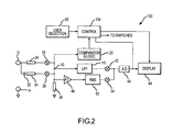
- Figure 2 is a block diagram of an AC/DC voltage measuring instrument according to one example of the invention.
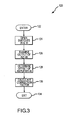
- Figure 3 is a flow chart showing one example of a calibration procedure that may be used to calibrate any offset in an amplifier used in the voltage measuring instrument of Figure 2 .
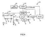
- Figure 4 is a block diagram of an AC/DC voltage measuring instrument according to another example of the invention.
- a voltage measurement instrument 100 is shown in Figure 2 .
- the instrument 100 has some similarities to the voltage measurement instrument 10 shown in Figure 1 , including the resistor 24 and switch 26 coupled between the terminal 12 and the test node 30 used to measure the amplitude of DC signals, and the capacitor 32, resistor 34 and switch 36 coupled between the terminal 12 and the test node 30 used to measure the amplitude of AC signals.
- the voltage measuring instrument 100 also includes the switch 42, which is closed to connect the test node 30 to the A/D converter 40 for measuring the amplitude of DC signals, and the amplifier 46, RMS circuit 50 and the switch 54, which is closed for measuring the amplitude of AC signals.
- the instrument 100 also includes a control unit 104 and the user selection device 62.
- the control unit 104 has been provided with a different reference number because it differs in structure and function from the structure and function of the control unit 60 used in the instrument 10.
- the voltage measurement instrument 100 of Figure 2 differs from the instrument 10 of Figure 1 in several important respects.
- the instrument 100 includes a low pass filter 110 in the path used to measure the amplitude of DC signals.
- the low pass filter 110 filters out any AC component in the signal to be measured so that the amplitude display does not fluctuate with different samples taken by the A/D converter 40.
- the instrument 100 thus provides a consistent and accurate measurement of the amplitude of DC signals.
- the output of the A/D converter 40 is connected to the control unit 104.
- the voltage measuring instrument 100 operates in essentially the same manner as the instrument 10 as explained below, except that it does not include the capacitor 48 used by the instrument 10 to eliminate any offset in the amplifier 46. Instead, as explained in greater detail below, the control unit 104 performs a calibration procedure to eliminate any offset in the amplifier 46.
- the most significant difference between the voltage measuring instrument 100 and the prior art instrument 10 is its operation in the automatic measurement mode.
- the control unit 104 closes the switches 26 , 54 and opens the switches 36, 42.
- the switches 26 , 54 remain closed and the switches 36, 42 remain open regardless of whether or not the comparator and logic circuit 20 detects zero crossings.
- the sole function of the comparator and logic circuit 20 is therefore to control the display 44 in the same manner it controls the display 44 in the automatic measurement mode in the prior art instrument 10, as explained above.
- the comparator and logic circuit 20 in the instrument 100 does not cause the control unit 104 to control any of the switches 26 , 54, 36, 42 in the automatic mode.
- the RMS circuit 50 By coupling the RMS circuit 50 to the terminal 12 without any intervening capacitor or other high pass filter, the RMS circuit is able to provide an accurate measurement of RMS amplitude regardless of the nature of the signal. If, for example, the signal is a DC signal with a large AC component, the RMS circuit will provide a true indication of the RMS value of the signal, which will take into account both the DC component and the AC component of the signal.
- the instrument 100 is able to dispense with the use of a capacitor to eliminate offsets of the amplifier 46 because the control unit 104 performs a calibration procedure. As shown in Figure 3 , this calibration procedure 120 is entered at 122 and the control unit 104 then opens switches 26 and 36. Resistor 38 then brings node 30 to zero volts. The control unit 104 then examines the output of the A/D converter 40. If the A/D converter 40 provides an RMS amplitude indication of other than zero, the control unit 104 determines at step 128 the offset of the amplifier 46 corresponding to this RMS amplitude. The control unit 104 then calculates a correction factor at step 130 that will be used for subsequent measurements in the AC measurement mode and the automatic measurement mode.
- the calibration procedure exits at step 134.
- a calibration procedure is shown in Figure 3 , it will be understood that other calibration procedures may be used to compensate for any offset of the amplifier 46 and RMS converted 50. Regardless of what calibration procedure is used, the use of a calibration procedure to compensate for offset of the amplifier 46 allows the RMS circuit 50 to be connected through a DC circuit path in the AC measurement mode and in the automatic measurement mode regardless of the nature of the signals applied between the terminals 12, 14. As a result, the voltage measuring instrument 100 is able to provide more accurate measurements when the amplitude of a signal has both AC and DC components.
- FIG. 4 Another example of a voltage measuring instrument 140 is shown in Figure 4 .
- the voltage measuring instrument 140 includes all of the same components that are used in the voltage measuring instrument 100 of Figure 2 operating in essentially the same manner.
- the instrument 140 differs from the instrument 100 by connecting the comparator and logic circuit 20 to the terminal 12 through a resistor 144 rather than connecting it directly to the test node 30 as in the instrument 100.
Landscapes
- Physics & Mathematics (AREA)
- General Physics & Mathematics (AREA)
- Engineering & Computer Science (AREA)
- Power Engineering (AREA)
- Measurement Of Current Or Voltage (AREA)
- Measuring Instrument Details And Bridges, And Automatic Balancing Devices (AREA)
Abstract
Description
- This invention relates to test and measurement equipment, and, more particularly, to a circuit and method for switching a signal to an alternating current ("AC") and direct current ("DC") voltage measurement instrument in a manner that allows accurate voltage measurements.
- Instruments for measuring the voltage of an AC or DC signal have been in existence for a long time, and they are in common use in a wide variety of fields. Early voltage measuring instruments, commonly known as "volt-ohm meters," used an analog meter having a pointer with an angular position indicative of the amplitude of a DC voltage. Such meters could also measure the amplitude of AC signals by rectifying the AC signal and scaling the amplitude to correspond to the root-mean-squared (RMS") value of the signal. Later volt-ohm meters used a digital display, and were substantially more accurate than analog meters.
- Although conventional volt-ohm meters could measure the RMS amplitude of an AC signal, the accuracy of such measurement was based on the assumption that the AC signal had a sinusoidal waveshape. Such volt-ohm meters could not accurately measure the RMS amplitude of a non-sinusoidal AC signal. For this reason, true RMS meters were developed using a variety of techniques.
- A block diagram of a conventional AC/DC
voltage measuring instrument 10 is shown inFigure 1 . Theinstrument 10 includes a pair ofterminals terminal 14 is coupled to ground, and theterminal 12 is coupled to several devices. More specifically, theterminal 12 is coupled through aresistor 18 to a comparator andlogic circuit 20, through aresistor 24 and switch 26 totest node 30, and through acapacitor 32,resistor 34 and aswitch 36 to thetest node 30. Thetest node 30 is connected to ground through aresistor 38 to form a voltage divider with one of theresistors - The
test node 30 is connected to an analog-to-digital ("A/D")converter 40 through aswitch 42. A digital signal at the output of the A/D converter 40 is applied to adisplay 44, and/or it may be applied to other circuits or systems (not shown). Thetest node 30 is also connected to an input of anamplifier 46. An output of theamplifier 46 is coupled through acapacitor 48 to anRMS circuit 50, which provides an accurate measurement of RMS amplitude of a signal applied to its input. An output of theRMS circuit 50 is coupled through aswitch 54 to the A/D converter 40. - The
voltage measuring instrument 10 has three operating modes, namely a DC measurement mode, an AC measurement mode, and an automatic measurement mode. These modes are selected by acontrol unit 60 selectively closing theswitches control unit 60 is, in turn, controlled by either auser selection device 62 or an output from the comparator andlogic circuit 20, as explained in greater detail below. Thecontrol unit 60 is also connected to thedisplay 44 so that it can show the mode that is currently in use. In the DC measurement mode or the AC measurement mode, thecontrol unit 60 causes thedisplay 44 to display whatever mode is selected through theuser selection device 62. However, in the automatic measurement mode, thecontrol unit 60 is controlled by the comparator andlogic circuit 20 to cause thedisplay 44 to indicate "Automatic" and to also display "AC" if the comparator andlogic circuit 20 detects zero crossings and to otherwise display "Automatic" and "DC." - When the amplitude of a DC voltage is to be measured, the DC measurement mode is selected through the
user selection device 62. Theselection device 62 then causes thecontrol unit 60 to close theswitches switches switch 26 connects theinput terminal 12 to thetest node 30 so that theresistor 24 forms a voltage divider with theresistor 38. The amplitude of the voltage at thetest node 30 is thus proportional to the amplitude of the signal applied between theinput terminals test node 30 is connected by the closedswitch 42 directly to the A/D converter 40. The A/D then outputs a digital signal indicative of the amplitude of the signal applied between theterminals display 44 provides the user with an indication of the amplitude of the DC voltage applied between theterminals - When the amplitude of an AC voltage is to be measured, the AC measurement mode is selected, again through the
user selection device 62. Theselection device 62 then causes thecontrol unit 60 to close theswitches switches switch 36 connects theinput terminal 12 to thetest node 30 through thecapacitor 32 so that only an AC signal is coupled through theresistor 34, which forms a voltage divider with theresistor 38. The amplitude of the voltage at thetest node 30 is thus proportional to the amplitude of the AC signal applied between theinput terminals test node 30 is boosted by theamplifier 46 and coupled through thecapacitor 48 to the input of theRMS circuit 50. Although thecapacitor 32 passes only AC signals, use of thecapacitor 48 is desirable to eliminate offsets that are typically generated by theamplifier 46. In the AC measurement mode, the output of theRMS circuit 50 is coupled through the closedswitch 54 to the A/D converter 40. The A/D converter 40 thus outputs a digital signal indicative of the RMS amplitude of the AC signal applied between theterminals display 44. - In the automatic measurement mode, the
voltage measuring instrument 10 switches between the DC measurement mode and the AC measurement mode based on the nature of the signal applied between theterminals logic circuit 20 detecting zero crossings of the signal to be measured. If thecircuit 20 detects zero crossings of the signal applied between theterminals control unit 60, which closes theswitches instrument 10 in the AC measurement mode, as explained above. If thecircuit 20 does not detect zero crossings, it assumes the signal applied between theterminals circuit 20 therefore sends a corresponding signal to thecontrol unit 60, which closes theswitches instrument 10 in the DC measurement mode, as also explained above. - The
voltage measuring instrument 10 shown inFigure 1 works well in many applications, particularly where the signal to be measured is a pure DC signal or a pure AC signal. However, it does not provide accurate results where the signal to be measured is a DC signal with an AC component or an AC signal having a DC offset. If the AC component is sufficiently large in relation to the DC offset, the comparator andlogic circuit 20 will detect zero crossings and therefore switch theinstrument 10 to the AC measurement mode. However, thecapacitors RMS circuit 50 will therefore produce a digital output that is indicative of the RMS amplitude of only the AC component. Yet the true RMS amplitude is affected by the DC component as well as the AC component. - Another problem develops if the AC component is relatively small in relation to the DC offset. In such case, the comparator and
logic circuit 20 will not detect zero crossings and therefore switch theinstrument 10 to the DC measurement mode. Theinstrument 10 will then provide spurious measurements of the DC amplitude of the signal, which will vary depending upon the sample point used by the A/D converter 40. These inconsistent measurements may indicate to the user that the DC voltage is continuously changing when, in fact, it is constant. - There is therefore a need for voltage measuring instrument and method that can provide accurate measurements of the voltage of signals in an Automatic measurement mode, including DC signals with an AC component or AC signals having a DC offset.
- A voltage measurement instrument and method measures the amplitude of an input signal in either a DC measurement mode, and AC measurement mode or an automatic measurement mode. In the DC measurement mode, the amplitude of the input signal is sampled by an analog-to-digital converter, which generates a digital value corresponding to the amplitude of the sample. In the AC measurement mode, the input signal is coupled through a capacitor to an RMS circuit, which determines the RMS amplitude of the input signal after being coupled through the capacitor. A digital value corresponding to the RMS amplitude is then generated. In the automatic measurement mode, the input signal is coupled directly to the RMS circuit without first coupling the input signal through a capacitor. In the automatic mode, the input signal is preferably coupled to the RMS circuit through an amplifier. The voltage measurement instrument performs a calibration procedure to calculate a correction factor to compensate for any offset generated by the amplifier. This correction factor is used in the automatic mode to display a corrected RMS amplitude value.
-
Figure 1 is a block diagram of one example of a conventional AC/DC voltage measuring instrument. -
Figure 2 is a block diagram of an AC/DC voltage measuring instrument according to one example of the invention. -
Figure 3 is a flow chart showing one example of a calibration procedure that may be used to calibrate any offset in an amplifier used in the voltage measuring instrument ofFigure 2 . -
Figure 4 is a block diagram of an AC/DC voltage measuring instrument according to another example of the invention. - A
voltage measurement instrument 100 according to one example of the invention is shown inFigure 2 . Theinstrument 100 has some similarities to thevoltage measurement instrument 10 shown inFigure 1 , including theresistor 24 and switch 26 coupled between the terminal 12 and thetest node 30 used to measure the amplitude of DC signals, and thecapacitor 32,resistor 34 and switch 36 coupled between the terminal 12 and thetest node 30 used to measure the amplitude of AC signals. Thevoltage measuring instrument 100 also includes theswitch 42, which is closed to connect thetest node 30 to the A/D converter 40 for measuring the amplitude of DC signals, and theamplifier 46,RMS circuit 50 and theswitch 54, which is closed for measuring the amplitude of AC signals. Finally, theinstrument 100 also includes acontrol unit 104 and theuser selection device 62. However, thecontrol unit 104 has been provided with a different reference number because it differs in structure and function from the structure and function of thecontrol unit 60 used in theinstrument 10. - The
voltage measurement instrument 100 ofFigure 2 differs from theinstrument 10 ofFigure 1 in several important respects. First, theinstrument 100 includes alow pass filter 110 in the path used to measure the amplitude of DC signals. Thelow pass filter 110 filters out any AC component in the signal to be measured so that the amplitude display does not fluctuate with different samples taken by the A/D converter 40. Theinstrument 100 thus provides a consistent and accurate measurement of the amplitude of DC signals. Additionally, for reasons that will also be explained below, the output of the A/D converter 40 is connected to thecontrol unit 104. - In the AC measurement mode, the
voltage measuring instrument 100 operates in essentially the same manner as theinstrument 10 as explained below, except that it does not include thecapacitor 48 used by theinstrument 10 to eliminate any offset in theamplifier 46. Instead, as explained in greater detail below, thecontrol unit 104 performs a calibration procedure to eliminate any offset in theamplifier 46. - The most significant difference between the
voltage measuring instrument 100 and theprior art instrument 10 is its operation in the automatic measurement mode. When the automatic measurement mode is selected using theuser selection device 62, thecontrol unit 104 closes theswitches switches switches switches logic circuit 20 detects zero crossings. The sole function of the comparator andlogic circuit 20 is therefore to control thedisplay 44 in the same manner it controls thedisplay 44 in the automatic measurement mode in theprior art instrument 10, as explained above. Unlike the comparator andlogic circuit 20 in theconventional instrument 10, the comparator andlogic circuit 20 in theinstrument 100 does not cause thecontrol unit 104 to control any of theswitches - By coupling the
RMS circuit 50 to the terminal 12 without any intervening capacitor or other high pass filter, the RMS circuit is able to provide an accurate measurement of RMS amplitude regardless of the nature of the signal. If, for example, the signal is a DC signal with a large AC component, the RMS circuit will provide a true indication of the RMS value of the signal, which will take into account both the DC component and the AC component of the signal. - As mentioned above, the
instrument 100 is able to dispense with the use of a capacitor to eliminate offsets of theamplifier 46 because thecontrol unit 104 performs a calibration procedure. As shown inFigure 3 , thiscalibration procedure 120 is entered at 122 and thecontrol unit 104 then opensswitches Resistor 38 then bringsnode 30 to zero volts. Thecontrol unit 104 then examines the output of the A/D converter 40. If the A/D converter 40 provides an RMS amplitude indication of other than zero, thecontrol unit 104 determines atstep 128 the offset of theamplifier 46 corresponding to this RMS amplitude. Thecontrol unit 104 then calculates a correction factor atstep 130 that will be used for subsequent measurements in the AC measurement mode and the automatic measurement mode. Finally, the calibration procedure exits atstep 134. Although one example of a calibration procedure is shown inFigure 3 , it will be understood that other calibration procedures may be used to compensate for any offset of theamplifier 46 and RMS converted 50. Regardless of what calibration procedure is used, the use of a calibration procedure to compensate for offset of theamplifier 46 allows theRMS circuit 50 to be connected through a DC circuit path in the AC measurement mode and in the automatic measurement mode regardless of the nature of the signals applied between theterminals voltage measuring instrument 100 is able to provide more accurate measurements when the amplitude of a signal has both AC and DC components. - Another example of a
voltage measuring instrument 140 is shown inFigure 4 . Thevoltage measuring instrument 140 includes all of the same components that are used in thevoltage measuring instrument 100 ofFigure 2 operating in essentially the same manner. Theinstrument 140 differs from theinstrument 100 by connecting the comparator andlogic circuit 20 to the terminal 12 through aresistor 144 rather than connecting it directly to thetest node 30 as in theinstrument 100. - Although the present invention has been described with reference to the disclosed embodiments, persons skilled in the art will recognize that changes may be made in form and detail without departing from the spirit and scope of the invention. Such modifications are well within the skill of those ordinarily skilled in the art. Accordingly, the invention is not limited except as by the appended claims.
Claims (21)
- An AC/DC voltage measuring instrument, comprising:an analog-to-digital converter operable to generate a digital output signal indicative of the amplitude of a signal received by the analog-to-digital converter;an RMS circuit structured to generate an RMS output signal indicative of the RMS amplitude of a signal received by the RMS circuit;a capacitor;a display coupled structured to display a value corresponding to a digital input signal, the digital input signal being based on the digital output signal received from the analog-to-digital converter; anda switching circuit operable in a DC mode, an AC mode, or an automatic mode, the switching circuit being operable in the DC mode to couple an input terminal to the analog-to-digital converter, being operable in the AC mode to couple the input terminal to the RMS circuit through the capacitor and to couple the RMS output signal from the RMS circuit to the analog-to-digital converter, and being operable in the automatic mode to couple the input terminal to the RMS circuit without coupling the input terminal through the capacitor and to couple the RMS output signal from the RMS circuit to the analog-to-digital converter.
- The AC/DC voltage measuring instrument of claim 1, further comprising a comparator and logic circuit coupled to the input terminal and to the display, the comparator and logic circuit being operable in the automatic mode to detect zero crossings of an input signal applied to the input terminal and to cause the display to annunciate operation in the AC mode responsive thereto.
- The AC/DC voltage measuring instrument of claim 2 wherein the switching circuit operates independently of the comparator and logic circuit.
- The AC/DC voltage measuring instrument of one of claims 1 to 3, further comprising an amplifier coupled between the input terminal and the RMS circuit in the automatic mode.
- The AC/DC voltage measuring instrument of claim 4 wherein the amplifier is further coupled between the input terminal and the RMS circuit in the AC mode.
- The AC/DC voltage measuring instrument of claim 4 or 5, further comprising a control unit coupled to receive the digital output signal from the analog-to-digital converter, the control unit further being operable in the automatic mode to perform a calibration procedure to compensate for any offset in the amplifier and to apply to the display a digital input signal corresponding to the digit output signal from the analog-to-digital converter compensated for any offset of the amplifier.
- The AC/DC voltage measuring instrument of claim 6, further comprising a switch coupled between the input terminal and a reference voltage, and wherein the control unit is operable to perform the calibration procedure by closing the switch, examining the output of the analog-to-digital converter to determine the amplitude of any signal output from the amplifier, calculating a correction factor based on the determined amplitude, and using the correction factor and the digit output signal from the analog-to-digital converter to generate the digital input signal applied to the display.
- The AC/DC voltage measuring instrument of claim 6 or 7, wherein the control unit is also operable in the AC mode to perform the calibration procedure.
- A voltage measuring instrument, comprising:an analog-to-digital converter operable to generate a digital output signal indicative of the amplitude of a signal received by the analog-to-digital converter;an RMS circuit structured to generate an RMS output signal indicative of the RMS amplitude of a signal received by the RMS circuit;a capacitor;an amplifier;a display coupled structured to display a value corresponding to a digital input signal, the digital input signal being based on the digital output signal received from the analog-to-digital converter;a switching circuit operable in an AC mode or an automatic mode, the switching circuit being operable in the AC mode to couple the input terminal to the RMS circuit through the capacitor and to couple the RMS output signal from the RMS circuit to the analog-to-digital converter, and being operable in the automatic mode to couple the input terminal to the RMS circuit through the amplifier without coupling the input terminal through the capacitor and to couple the RMS output signal from the RMS circuit to the analog-to-digital converter; anda control unit structured to control the operation of the switching circuit, the control unit further coupled to receive the digital output signal from the analog-to-digital converter, the control unit being operable in the automatic mode to perform a calibration procedure to compensate for any offset in the amplifier and to apply to the display a digital input signal corresponding to the digit output signal from the analog-to-digital converter compensated for any offset of the amplifier.
- The voltage measuring instrument of claim 9, further comprising a switch coupled between the input terminal and a reference voltage, and wherein the control unit is operable to perform the calibration procedure by closing the switch, examining the output of the analog-to-digital converter to determine the amplitude of any signal output from the amplifier, calculating a correction factor based on the determined amplitude, and using the correction factor and the digit output signal from the analog-to-digital converter to generate the digital input signal applied to the display.
- The voltage measuring instrument of claim 9 or 10 wherein the control unit is further operable in the AC mode to perform the calibration procedure.
- The voltage measuring instrument of one of claims 9-11, further comprising a comparator and logic circuit coupled to the input terminal and to the display, the comparator and logic circuit being operable in the automatic mode to detect zero crossings of an input signal applied to the input terminal and to cause the display to annunciate operation in the AC mode responsive thereto.
- The voltage measuring instrument of claim 12 wherein the switching circuit operates independently of the comparator and logic circuit.
- A method of measuring the amplitude of an input signal in either a DC measurement mode, and AC measurement mode or an automatic measurement mode, the method comprising:in the DC measurement mode, sampling the amplitude of the input signal and converting the sample to a digital value corresponding to the amplitude of the sample;in the AC measurement mode, coupling the input signal through a capacitor, determining the RMS amplitude of the input signal coupled through the capacitor, and providing a digital value corresponding to the RMS amplitude; andin the automatic measurement mode, determining the RMS amplitude of the input signal without first coupling the input signal through the capacitor, and providing a digital value corresponding to the RMS amplitude of the input signal.
- The method of claim 14, further comprising displaying the digital value corresponding to the amplitude of the sample in the DC measurement mode, and displaying the digital value corresponding to the RMS amplitude in the AC measurement mode and the automatic mode.
- The method of claim 14 or 15, further comprising low-pass filtering the input signal in the DC measurement mode before sampling the amplitude of the input signal.
- The method of one of claims 14-16, further comprising amplifying the input signal in the automatic measurement mode before determining the RMS amplitude of the input signal.
- The method of claim 17, further comprising performing a calibration procedure in the automatic measurement mode to compensate for any offset generated during the act of amplifying the input signal.
- The method of claim 18 wherein the calibration procedure comprises:making the input signal have a predetermined voltage;examining the amplified input signal to determine if the amplitude of the amplified input signal corresponds to the predetermined voltage;if the amplitude of the amplified input signal does not correspond to the predetermined voltage, calculating a correction factor; andusing the correction factor in determining the RMS amplitude of the input signal.
- In a voltage measuring instrument having an amplifier coupled to receive an input signal from an input terminal and being operable to generate an amplified input signal, an RMS circuit coupled to receive the amplified input signal from the amplifier and being operable to generate an RMS output signal indicative of the RMS amplitude of the amplified input signal, and an analog-to-digital converter coupled to receive the RMS output signal from the RMS circuit and being operable to generate a digital output signal indicative of the amplitude of the RMS output signal, a method of calibrating the voltage measuring system to compensate for any offset in the amplifier, the method comprising:connecting the input terminal to a predetermined voltage;examining the output of the analog-to-digital converter to determine the amplitude of any signal output from the amplifier;calculating a correction factor based on the determined amplitude; andusing the correction factor and the digit output signal from the analog-to-digital converter to generate a corrected digital output signal.
- The method of claim 20 wherein the predetermined voltage comprises ground potential.
Applications Claiming Priority (1)
| Application Number | Priority Date | Filing Date | Title |
|---|---|---|---|
| US11/633,979 US7642788B2 (en) | 2006-12-04 | 2006-12-04 | Voltage measurement instrument and method having improved automatic mode operation |
Publications (3)
| Publication Number | Publication Date |
|---|---|
| EP1930736A2 true EP1930736A2 (en) | 2008-06-11 |
| EP1930736A3 EP1930736A3 (en) | 2008-07-30 |
| EP1930736B1 EP1930736B1 (en) | 2017-01-04 |
Family
ID=39135236
Family Applications (1)
| Application Number | Title | Priority Date | Filing Date |
|---|---|---|---|
| EP07023294.7A Active EP1930736B1 (en) | 2006-12-04 | 2007-11-30 | Voltage measurement instrument and method having improved automatic mode operation |
Country Status (3)
| Country | Link |
|---|---|
| US (3) | US7642788B2 (en) |
| EP (1) | EP1930736B1 (en) |
| CN (1) | CN101231310B (en) |
Families Citing this family (22)
| Publication number | Priority date | Publication date | Assignee | Title |
|---|---|---|---|---|
| TWI366168B (en) * | 2007-05-02 | 2012-06-11 | Novatek Microelectronics Corp | Controlling device of liquid crystal display |
| US7855544B1 (en) * | 2008-05-01 | 2010-12-21 | Keithley Instruments, Inc. | AC low current probe card |
| CN101387696B (en) * | 2008-11-07 | 2012-05-30 | 河南电力试验研究院 | Calibration system and method for digital AC/DC tester |
| CN101806820B (en) * | 2010-03-16 | 2012-08-01 | 安徽皖仪科技股份有限公司 | Automatic zero-setting method for software |
| CN101937069B (en) * | 2010-09-08 | 2013-11-27 | 珠海中慧微电子有限公司 | Voltage characteristic detection system and method of SOC (System On Chip) intelligent electric meter |
| US8615382B2 (en) * | 2011-01-27 | 2013-12-24 | Tektronix, Inc. | Test and measurement instrument with common presentation of time domain data |
| CN102291138B (en) | 2011-07-08 | 2013-11-27 | 东南大学 | A random time-to-digital converter |
| US9151818B2 (en) * | 2011-11-08 | 2015-10-06 | Analog Devices Global | Voltage measurement |
| EP3736578B1 (en) | 2011-09-12 | 2025-03-05 | Analog Devices International Unlimited Company | Current measurement |
| US9804204B2 (en) * | 2011-09-21 | 2017-10-31 | Honeywell International Inc. | Method of implementation of peak hold in a phasing voltmeter |
| GB201120295D0 (en) | 2011-11-24 | 2012-01-04 | Metroic Ltd | Current measurement apparatus |
| US8952742B2 (en) * | 2012-10-31 | 2015-02-10 | Marvell World Trade Ltd. | Highly accurate true RMS power detector for cellular applications |
| CN103424589B (en) * | 2013-07-30 | 2016-07-06 | 国家电网公司 | A kind of voltage transformer calibration microvolt level low level signal amplification device |
| JP6716373B2 (en) * | 2016-07-12 | 2020-07-01 | 日置電機株式会社 | measuring device |
| US10254375B2 (en) | 2016-11-11 | 2019-04-09 | Fluke Corporation | Proving unit for voltage measurement systems |
| US10359494B2 (en) | 2016-11-11 | 2019-07-23 | Fluke Corporation | Proving unit for non-contact voltage measurement systems |
| CN108089575B (en) * | 2016-11-23 | 2021-08-10 | 苏州宝时得电动工具有限公司 | Self-moving equipment positioning device and method |
| US10539643B2 (en) | 2017-09-01 | 2020-01-21 | Fluke Corporation | Proving unit for use with electrical test tools |
| US11199425B2 (en) | 2018-09-27 | 2021-12-14 | Apple Inc. | Dynamic current control of a transmitter for magnetic proximity sensing |
| US11422207B2 (en) | 2018-09-27 | 2022-08-23 | Apple Inc. | Configurable AC/DC sensor readout architecture |
| CN110726951B (en) * | 2019-10-10 | 2022-04-15 | 深圳市航天新源科技有限公司 | Method for detecting connection state of power supply far-end voltage compensation end |
| CN117031100B (en) * | 2023-09-28 | 2026-01-06 | 深圳市鼎阳科技股份有限公司 | A front-end circuit of a multimeter and the multimeter itself. |
Citations (3)
| Publication number | Priority date | Publication date | Assignee | Title |
|---|---|---|---|---|
| US5117180A (en) | 1991-06-06 | 1992-05-26 | Hewlett-Packard Company | Method and apparatus for measuring RMS values |
| US5144226A (en) | 1991-05-17 | 1992-09-01 | Core Industries | Multi-mode measuring system |
| EP0696742A2 (en) | 1994-08-11 | 1996-02-14 | Fluke Corporation | Direct digital synthesis component test |
Family Cites Families (6)
| Publication number | Priority date | Publication date | Assignee | Title |
|---|---|---|---|---|
| US4933631A (en) * | 1987-01-29 | 1990-06-12 | John Fluke Mfg. Co., Inc. | Digital AC meter |
| US5250893A (en) * | 1992-01-31 | 1993-10-05 | Tegam, Inc. | Digital voltmeter |
| US6154503A (en) * | 1996-06-07 | 2000-11-28 | Sharp Kk Corporation | Automatic gain control system that responds to baseband signal distortion |
| JP3684802B2 (en) * | 1997-05-09 | 2005-08-17 | 株式会社村田製作所 | Electronic component resistance measuring device |
| US6380726B1 (en) | 1998-05-08 | 2002-04-30 | Tektronix, Inc. | Smart auto-ranging RMS measurement method and apparatus |
| JP4179205B2 (en) * | 2004-03-29 | 2008-11-12 | サンケン電気株式会社 | Voltage measuring device |
-
2006
- 2006-12-04 US US11/633,979 patent/US7642788B2/en active Active
-
2007
- 2007-11-30 EP EP07023294.7A patent/EP1930736B1/en active Active
- 2007-12-03 CN CN2007101933025A patent/CN101231310B/en active Active
-
2009
- 2009-11-30 US US12/627,811 patent/US8004286B2/en active Active
-
2011
- 2011-07-19 US US13/186,250 patent/US20110276300A1/en not_active Abandoned
Patent Citations (3)
| Publication number | Priority date | Publication date | Assignee | Title |
|---|---|---|---|---|
| US5144226A (en) | 1991-05-17 | 1992-09-01 | Core Industries | Multi-mode measuring system |
| US5117180A (en) | 1991-06-06 | 1992-05-26 | Hewlett-Packard Company | Method and apparatus for measuring RMS values |
| EP0696742A2 (en) | 1994-08-11 | 1996-02-14 | Fluke Corporation | Direct digital synthesis component test |
Also Published As
| Publication number | Publication date |
|---|---|
| EP1930736B1 (en) | 2017-01-04 |
| CN101231310B (en) | 2012-10-24 |
| US20110276300A1 (en) | 2011-11-10 |
| US20080129279A1 (en) | 2008-06-05 |
| US8004286B2 (en) | 2011-08-23 |
| US20100072981A1 (en) | 2010-03-25 |
| US7642788B2 (en) | 2010-01-05 |
| CN101231310A (en) | 2008-07-30 |
| EP1930736A3 (en) | 2008-07-30 |
Similar Documents
| Publication | Publication Date | Title |
|---|---|---|
| US8004286B2 (en) | Voltage measurement instrument and method having improved automatic mode operation | |
| US5294889A (en) | Battery operated capacitance measurement circuit | |
| US4825147A (en) | Capacitance measuring method and apparatus | |
| US4103225A (en) | System and method for determining capacitance and cable length in the presence of other circuit elements | |
| US4958294A (en) | Swept microwave power measurement system and method | |
| JPH1054851A (en) | Instrument for measuring output current of power source | |
| WO1993008477A1 (en) | SELF DIAGNOSTIC pH SENSOR | |
| RU2143120C1 (en) | Method and device for voltage measuring | |
| Atmanand et al. | A microcontroller-based quasi-balanced bridge for the measurement of L, C and R | |
| JP3580817B2 (en) | Measuring amplifier | |
| US5621329A (en) | Automatic self-calibration system for digital teraohmmeter | |
| US4321544A (en) | Method and improved apparatus for obtaining temperature-corrected readings of ion levels and readings of solution temperature | |
| CA2180611C (en) | Car space measurement apparatus | |
| US6239596B1 (en) | Total magnetic flux measuring device | |
| US3448378A (en) | Impedance measuring instrument having a voltage divider comprising a pair of amplifiers | |
| CA2414750C (en) | Method and apparatus employing a scaling factor for measuring and displaying an electrical parameter of an electrical system | |
| CN217786082U (en) | Automatic calibration inductance displacement sensor detection circuit | |
| JP2004093416A (en) | Voltage / current measuring device | |
| US20020180419A1 (en) | Precision rms measurement | |
| CN1309298A (en) | Tuning frequency measuring device for filter | |
| Cox et al. | An automatic rms/dc comparator | |
| JP2954449B2 (en) | Capacitance measuring circuit and LCR meter having the same | |
| KR900008302B1 (en) | Power factor measuring circuit and method of power meter | |
| US4156181A (en) | Ratio circuit | |
| CN223123118U (en) | Resistance detection circuit and resistance detector |
Legal Events
| Date | Code | Title | Description |
|---|---|---|---|
| PUAI | Public reference made under article 153(3) epc to a published international application that has entered the european phase |
Free format text: ORIGINAL CODE: 0009012 |
|
| AK | Designated contracting states |
Kind code of ref document: A2 Designated state(s): AT BE BG CH CY CZ DE DK EE ES FI FR GB GR HU IE IS IT LI LT LU LV MC MT NL PL PT RO SE SI SK TR |
|
| AX | Request for extension of the european patent |
Extension state: AL BA HR MK RS |
|
| PUAL | Search report despatched |
Free format text: ORIGINAL CODE: 0009013 |
|
| AK | Designated contracting states |
Kind code of ref document: A3 Designated state(s): AT BE BG CH CY CZ DE DK EE ES FI FR GB GR HU IE IS IT LI LT LU LV MC MT NL PL PT RO SE SI SK TR |
|
| AX | Request for extension of the european patent |
Extension state: AL BA HR MK RS |
|
| 17P | Request for examination filed |
Effective date: 20090105 |
|
| AKX | Designation fees paid |
Designated state(s): AT BE BG CH CY CZ DE DK EE ES FI FR GB GR HU IE IS IT LI LT LU LV MC MT NL PL PT RO SE SI SK TR |
|
| GRAP | Despatch of communication of intention to grant a patent |
Free format text: ORIGINAL CODE: EPIDOSNIGR1 |
|
| INTG | Intention to grant announced |
Effective date: 20160629 |
|
| GRAS | Grant fee paid |
Free format text: ORIGINAL CODE: EPIDOSNIGR3 |
|
| RAP1 | Party data changed (applicant data changed or rights of an application transferred) |
Owner name: FLUKE CORPORATION |
|
| GRAA | (expected) grant |
Free format text: ORIGINAL CODE: 0009210 |
|
| AK | Designated contracting states |
Kind code of ref document: B1 Designated state(s): AT BE BG CH CY CZ DE DK EE ES FI FR GB GR HU IE IS IT LI LT LU LV MC MT NL PL PT RO SE SI SK TR |
|
| REG | Reference to a national code |
Ref country code: GB Ref legal event code: FG4D |
|
| REG | Reference to a national code |
Ref country code: CH Ref legal event code: EP |
|
| REG | Reference to a national code |
Ref country code: AT Ref legal event code: REF Ref document number: 859760 Country of ref document: AT Kind code of ref document: T Effective date: 20170115 |
|
| REG | Reference to a national code |
Ref country code: IE Ref legal event code: FG4D |
|
| REG | Reference to a national code |
Ref country code: DE Ref legal event code: R096 Ref document number: 602007049381 Country of ref document: DE |
|
| REG | Reference to a national code |
Ref country code: LT Ref legal event code: MG4D Ref country code: NL Ref legal event code: MP Effective date: 20170104 |
|
| REG | Reference to a national code |
Ref country code: AT Ref legal event code: MK05 Ref document number: 859760 Country of ref document: AT Kind code of ref document: T Effective date: 20170104 |
|
| PG25 | Lapsed in a contracting state [announced via postgrant information from national office to epo] |
Ref country code: NL Free format text: LAPSE BECAUSE OF FAILURE TO SUBMIT A TRANSLATION OF THE DESCRIPTION OR TO PAY THE FEE WITHIN THE PRESCRIBED TIME-LIMIT Effective date: 20170104 |
|
| PG25 | Lapsed in a contracting state [announced via postgrant information from national office to epo] |
Ref country code: GR Free format text: LAPSE BECAUSE OF FAILURE TO SUBMIT A TRANSLATION OF THE DESCRIPTION OR TO PAY THE FEE WITHIN THE PRESCRIBED TIME-LIMIT Effective date: 20170405 Ref country code: FI Free format text: LAPSE BECAUSE OF FAILURE TO SUBMIT A TRANSLATION OF THE DESCRIPTION OR TO PAY THE FEE WITHIN THE PRESCRIBED TIME-LIMIT Effective date: 20170104 Ref country code: IS Free format text: LAPSE BECAUSE OF FAILURE TO SUBMIT A TRANSLATION OF THE DESCRIPTION OR TO PAY THE FEE WITHIN THE PRESCRIBED TIME-LIMIT Effective date: 20170504 Ref country code: LT Free format text: LAPSE BECAUSE OF FAILURE TO SUBMIT A TRANSLATION OF THE DESCRIPTION OR TO PAY THE FEE WITHIN THE PRESCRIBED TIME-LIMIT Effective date: 20170104 |
|
| PG25 | Lapsed in a contracting state [announced via postgrant information from national office to epo] |
Ref country code: PT Free format text: LAPSE BECAUSE OF FAILURE TO SUBMIT A TRANSLATION OF THE DESCRIPTION OR TO PAY THE FEE WITHIN THE PRESCRIBED TIME-LIMIT Effective date: 20170504 Ref country code: AT Free format text: LAPSE BECAUSE OF FAILURE TO SUBMIT A TRANSLATION OF THE DESCRIPTION OR TO PAY THE FEE WITHIN THE PRESCRIBED TIME-LIMIT Effective date: 20170104 Ref country code: BG Free format text: LAPSE BECAUSE OF FAILURE TO SUBMIT A TRANSLATION OF THE DESCRIPTION OR TO PAY THE FEE WITHIN THE PRESCRIBED TIME-LIMIT Effective date: 20170404 Ref country code: PL Free format text: LAPSE BECAUSE OF FAILURE TO SUBMIT A TRANSLATION OF THE DESCRIPTION OR TO PAY THE FEE WITHIN THE PRESCRIBED TIME-LIMIT Effective date: 20170104 Ref country code: SE Free format text: LAPSE BECAUSE OF FAILURE TO SUBMIT A TRANSLATION OF THE DESCRIPTION OR TO PAY THE FEE WITHIN THE PRESCRIBED TIME-LIMIT Effective date: 20170104 Ref country code: ES Free format text: LAPSE BECAUSE OF FAILURE TO SUBMIT A TRANSLATION OF THE DESCRIPTION OR TO PAY THE FEE WITHIN THE PRESCRIBED TIME-LIMIT Effective date: 20170104 Ref country code: LV Free format text: LAPSE BECAUSE OF FAILURE TO SUBMIT A TRANSLATION OF THE DESCRIPTION OR TO PAY THE FEE WITHIN THE PRESCRIBED TIME-LIMIT Effective date: 20170104 |
|
| REG | Reference to a national code |
Ref country code: DE Ref legal event code: R097 Ref document number: 602007049381 Country of ref document: DE |
|
| PG25 | Lapsed in a contracting state [announced via postgrant information from national office to epo] |
Ref country code: RO Free format text: LAPSE BECAUSE OF FAILURE TO SUBMIT A TRANSLATION OF THE DESCRIPTION OR TO PAY THE FEE WITHIN THE PRESCRIBED TIME-LIMIT Effective date: 20170104 Ref country code: EE Free format text: LAPSE BECAUSE OF FAILURE TO SUBMIT A TRANSLATION OF THE DESCRIPTION OR TO PAY THE FEE WITHIN THE PRESCRIBED TIME-LIMIT Effective date: 20170104 Ref country code: IT Free format text: LAPSE BECAUSE OF FAILURE TO SUBMIT A TRANSLATION OF THE DESCRIPTION OR TO PAY THE FEE WITHIN THE PRESCRIBED TIME-LIMIT Effective date: 20170104 Ref country code: SK Free format text: LAPSE BECAUSE OF FAILURE TO SUBMIT A TRANSLATION OF THE DESCRIPTION OR TO PAY THE FEE WITHIN THE PRESCRIBED TIME-LIMIT Effective date: 20170104 Ref country code: CZ Free format text: LAPSE BECAUSE OF FAILURE TO SUBMIT A TRANSLATION OF THE DESCRIPTION OR TO PAY THE FEE WITHIN THE PRESCRIBED TIME-LIMIT Effective date: 20170104 |
|
| PLBE | No opposition filed within time limit |
Free format text: ORIGINAL CODE: 0009261 |
|
| STAA | Information on the status of an ep patent application or granted ep patent |
Free format text: STATUS: NO OPPOSITION FILED WITHIN TIME LIMIT |
|
| REG | Reference to a national code |
Ref country code: FR Ref legal event code: PLFP Year of fee payment: 11 |
|
| PG25 | Lapsed in a contracting state [announced via postgrant information from national office to epo] |
Ref country code: DK Free format text: LAPSE BECAUSE OF FAILURE TO SUBMIT A TRANSLATION OF THE DESCRIPTION OR TO PAY THE FEE WITHIN THE PRESCRIBED TIME-LIMIT Effective date: 20170104 |
|
| 26N | No opposition filed |
Effective date: 20171005 |
|
| PG25 | Lapsed in a contracting state [announced via postgrant information from national office to epo] |
Ref country code: SI Free format text: LAPSE BECAUSE OF FAILURE TO SUBMIT A TRANSLATION OF THE DESCRIPTION OR TO PAY THE FEE WITHIN THE PRESCRIBED TIME-LIMIT Effective date: 20170104 |
|
| PG25 | Lapsed in a contracting state [announced via postgrant information from national office to epo] |
Ref country code: MC Free format text: LAPSE BECAUSE OF FAILURE TO SUBMIT A TRANSLATION OF THE DESCRIPTION OR TO PAY THE FEE WITHIN THE PRESCRIBED TIME-LIMIT Effective date: 20170104 |
|
| PG25 | Lapsed in a contracting state [announced via postgrant information from national office to epo] |
Ref country code: LI Free format text: LAPSE BECAUSE OF NON-PAYMENT OF DUE FEES Effective date: 20171130 Ref country code: CH Free format text: LAPSE BECAUSE OF NON-PAYMENT OF DUE FEES Effective date: 20171130 |
|
| PG25 | Lapsed in a contracting state [announced via postgrant information from national office to epo] |
Ref country code: LU Free format text: LAPSE BECAUSE OF NON-PAYMENT OF DUE FEES Effective date: 20171130 |
|
| REG | Reference to a national code |
Ref country code: BE Ref legal event code: MM Effective date: 20171130 |
|
| REG | Reference to a national code |
Ref country code: IE Ref legal event code: MM4A |
|
| PG25 | Lapsed in a contracting state [announced via postgrant information from national office to epo] |
Ref country code: MT Free format text: LAPSE BECAUSE OF NON-PAYMENT OF DUE FEES Effective date: 20171130 |
|
| PG25 | Lapsed in a contracting state [announced via postgrant information from national office to epo] |
Ref country code: IE Free format text: LAPSE BECAUSE OF NON-PAYMENT OF DUE FEES Effective date: 20171130 |
|
| PG25 | Lapsed in a contracting state [announced via postgrant information from national office to epo] |
Ref country code: BE Free format text: LAPSE BECAUSE OF NON-PAYMENT OF DUE FEES Effective date: 20171130 |
|
| PG25 | Lapsed in a contracting state [announced via postgrant information from national office to epo] |
Ref country code: HU Free format text: LAPSE BECAUSE OF FAILURE TO SUBMIT A TRANSLATION OF THE DESCRIPTION OR TO PAY THE FEE WITHIN THE PRESCRIBED TIME-LIMIT; INVALID AB INITIO Effective date: 20071130 |
|
| PG25 | Lapsed in a contracting state [announced via postgrant information from national office to epo] |
Ref country code: CY Free format text: LAPSE BECAUSE OF NON-PAYMENT OF DUE FEES Effective date: 20170104 |
|
| PG25 | Lapsed in a contracting state [announced via postgrant information from national office to epo] |
Ref country code: TR Free format text: LAPSE BECAUSE OF FAILURE TO SUBMIT A TRANSLATION OF THE DESCRIPTION OR TO PAY THE FEE WITHIN THE PRESCRIBED TIME-LIMIT Effective date: 20170104 |
|
| PGFP | Annual fee paid to national office [announced via postgrant information from national office to epo] |
Ref country code: DE Payment date: 20251128 Year of fee payment: 19 |
|
| PGFP | Annual fee paid to national office [announced via postgrant information from national office to epo] |
Ref country code: GB Payment date: 20251127 Year of fee payment: 19 |
|
| PGFP | Annual fee paid to national office [announced via postgrant information from national office to epo] |
Ref country code: FR Payment date: 20251125 Year of fee payment: 19 |