EP1930690A1 - Method and device for dynamically determining a slope of a road - Google Patents
Method and device for dynamically determining a slope of a road Download PDFInfo
- Publication number
- EP1930690A1 EP1930690A1 EP06025364A EP06025364A EP1930690A1 EP 1930690 A1 EP1930690 A1 EP 1930690A1 EP 06025364 A EP06025364 A EP 06025364A EP 06025364 A EP06025364 A EP 06025364A EP 1930690 A1 EP1930690 A1 EP 1930690A1
- Authority
- EP
- European Patent Office
- Prior art keywords
- acc
- tot
- vehicle
- slope
- road
- Prior art date
- Legal status (The legal status is an assumption and is not a legal conclusion. Google has not performed a legal analysis and makes no representation as to the accuracy of the status listed.)
- Granted
Links
Images

Classifications
-
- G—PHYSICS
- G01—MEASURING; TESTING
- G01C—MEASURING DISTANCES, LEVELS OR BEARINGS; SURVEYING; NAVIGATION; GYROSCOPIC INSTRUMENTS; PHOTOGRAMMETRY OR VIDEOGRAMMETRY
- G01C21/00—Navigation; Navigational instruments not provided for in groups G01C1/00 - G01C19/00
- G01C21/26—Navigation; Navigational instruments not provided for in groups G01C1/00 - G01C19/00 specially adapted for navigation in a road network
-
- B—PERFORMING OPERATIONS; TRANSPORTING
- B60—VEHICLES IN GENERAL
- B60W—CONJOINT CONTROL OF VEHICLE SUB-UNITS OF DIFFERENT TYPE OR DIFFERENT FUNCTION; CONTROL SYSTEMS SPECIALLY ADAPTED FOR HYBRID VEHICLES; ROAD VEHICLE DRIVE CONTROL SYSTEMS FOR PURPOSES NOT RELATED TO THE CONTROL OF A PARTICULAR SUB-UNIT
- B60W40/00—Estimation or calculation of non-directly measurable driving parameters for road vehicle drive control systems not related to the control of a particular sub unit, e.g. by using mathematical models
- B60W40/02—Estimation or calculation of non-directly measurable driving parameters for road vehicle drive control systems not related to the control of a particular sub unit, e.g. by using mathematical models related to ambient conditions
- B60W40/06—Road conditions
- B60W40/076—Slope angle of the road
-
- G—PHYSICS
- G01—MEASURING; TESTING
- G01C—MEASURING DISTANCES, LEVELS OR BEARINGS; SURVEYING; NAVIGATION; GYROSCOPIC INSTRUMENTS; PHOTOGRAMMETRY OR VIDEOGRAMMETRY
- G01C9/00—Measuring inclination, e.g. by clinometers, by levels
-
- B—PERFORMING OPERATIONS; TRANSPORTING
- B60—VEHICLES IN GENERAL
- B60G—VEHICLE SUSPENSION ARRANGEMENTS
- B60G2400/00—Indexing codes relating to detected, measured or calculated conditions or factors
- B60G2400/10—Acceleration; Deceleration
- B60G2400/102—Acceleration; Deceleration vertical
-
- B—PERFORMING OPERATIONS; TRANSPORTING
- B60—VEHICLES IN GENERAL
- B60G—VEHICLE SUSPENSION ARRANGEMENTS
- B60G2400/00—Indexing codes relating to detected, measured or calculated conditions or factors
- B60G2400/10—Acceleration; Deceleration
- B60G2400/106—Acceleration; Deceleration longitudinal with regard to vehicle, e.g. braking
-
- B—PERFORMING OPERATIONS; TRANSPORTING
- B60—VEHICLES IN GENERAL
- B60G—VEHICLE SUSPENSION ARRANGEMENTS
- B60G2400/00—Indexing codes relating to detected, measured or calculated conditions or factors
- B60G2400/20—Speed
- B60G2400/204—Vehicle speed
-
- B—PERFORMING OPERATIONS; TRANSPORTING
- B60—VEHICLES IN GENERAL
- B60G—VEHICLE SUSPENSION ARRANGEMENTS
- B60G2400/00—Indexing codes relating to detected, measured or calculated conditions or factors
- B60G2400/80—Exterior conditions
- B60G2400/82—Ground surface
- B60G2400/824—Travel path sensing; Track monitoring
-
- B—PERFORMING OPERATIONS; TRANSPORTING
- B60—VEHICLES IN GENERAL
- B60G—VEHICLE SUSPENSION ARRANGEMENTS
- B60G2600/00—Indexing codes relating to particular elements, systems or processes used on suspension systems or suspension control systems
- B60G2600/70—Computer memory; Data storage, e.g. maps for adaptive control
-
- B—PERFORMING OPERATIONS; TRANSPORTING
- B60—VEHICLES IN GENERAL
- B60G—VEHICLE SUSPENSION ARRANGEMENTS
- B60G2800/00—Indexing codes relating to the type of movement or to the condition of the vehicle and to the end result to be achieved by the control action
- B60G2800/01—Attitude or posture control
- B60G2800/019—Inclination due to load distribution or road gradient
- B60G2800/0192—Inclination due to load distribution or road gradient longitudinal with regard to vehicle
-
- B—PERFORMING OPERATIONS; TRANSPORTING
- B60—VEHICLES IN GENERAL
- B60G—VEHICLE SUSPENSION ARRANGEMENTS
- B60G2800/00—Indexing codes relating to the type of movement or to the condition of the vehicle and to the end result to be achieved by the control action
- B60G2800/70—Estimating or calculating vehicle parameters or state variables
- B60G2800/702—Improving accuracy of a sensor signal
-
- B—PERFORMING OPERATIONS; TRANSPORTING
- B60—VEHICLES IN GENERAL
- B60G—VEHICLE SUSPENSION ARRANGEMENTS
- B60G2800/00—Indexing codes relating to the type of movement or to the condition of the vehicle and to the end result to be achieved by the control action
- B60G2800/90—System Controller type
- B60G2800/92—ABS - Brake Control
-
- B—PERFORMING OPERATIONS; TRANSPORTING
- B60—VEHICLES IN GENERAL
- B60W—CONJOINT CONTROL OF VEHICLE SUB-UNITS OF DIFFERENT TYPE OR DIFFERENT FUNCTION; CONTROL SYSTEMS SPECIALLY ADAPTED FOR HYBRID VEHICLES; ROAD VEHICLE DRIVE CONTROL SYSTEMS FOR PURPOSES NOT RELATED TO THE CONTROL OF A PARTICULAR SUB-UNIT
- B60W2520/00—Input parameters relating to overall vehicle dynamics
- B60W2520/10—Longitudinal speed
- B60W2520/105—Longitudinal acceleration
-
- B—PERFORMING OPERATIONS; TRANSPORTING
- B60—VEHICLES IN GENERAL
- B60W—CONJOINT CONTROL OF VEHICLE SUB-UNITS OF DIFFERENT TYPE OR DIFFERENT FUNCTION; CONTROL SYSTEMS SPECIALLY ADAPTED FOR HYBRID VEHICLES; ROAD VEHICLE DRIVE CONTROL SYSTEMS FOR PURPOSES NOT RELATED TO THE CONTROL OF A PARTICULAR SUB-UNIT
- B60W2552/00—Input parameters relating to infrastructure
- B60W2552/15—Road slope, i.e. the inclination of a road segment in the longitudinal direction
-
- B—PERFORMING OPERATIONS; TRANSPORTING
- B60—VEHICLES IN GENERAL
- B60W—CONJOINT CONTROL OF VEHICLE SUB-UNITS OF DIFFERENT TYPE OR DIFFERENT FUNCTION; CONTROL SYSTEMS SPECIALLY ADAPTED FOR HYBRID VEHICLES; ROAD VEHICLE DRIVE CONTROL SYSTEMS FOR PURPOSES NOT RELATED TO THE CONTROL OF A PARTICULAR SUB-UNIT
- B60W2556/00—Input parameters relating to data
- B60W2556/45—External transmission of data to or from the vehicle
- B60W2556/50—External transmission of data to or from the vehicle of positioning data, e.g. GPS [Global Positioning System] data
-
- B—PERFORMING OPERATIONS; TRANSPORTING
- B60—VEHICLES IN GENERAL
- B60W—CONJOINT CONTROL OF VEHICLE SUB-UNITS OF DIFFERENT TYPE OR DIFFERENT FUNCTION; CONTROL SYSTEMS SPECIALLY ADAPTED FOR HYBRID VEHICLES; ROAD VEHICLE DRIVE CONTROL SYSTEMS FOR PURPOSES NOT RELATED TO THE CONTROL OF A PARTICULAR SUB-UNIT
- B60W2710/00—Output or target parameters relating to a particular sub-units
- B60W2710/18—Braking system
-
- B—PERFORMING OPERATIONS; TRANSPORTING
- B60—VEHICLES IN GENERAL
- B60W—CONJOINT CONTROL OF VEHICLE SUB-UNITS OF DIFFERENT TYPE OR DIFFERENT FUNCTION; CONTROL SYSTEMS SPECIALLY ADAPTED FOR HYBRID VEHICLES; ROAD VEHICLE DRIVE CONTROL SYSTEMS FOR PURPOSES NOT RELATED TO THE CONTROL OF A PARTICULAR SUB-UNIT
- B60W40/00—Estimation or calculation of non-directly measurable driving parameters for road vehicle drive control systems not related to the control of a particular sub unit, e.g. by using mathematical models
- B60W40/02—Estimation or calculation of non-directly measurable driving parameters for road vehicle drive control systems not related to the control of a particular sub unit, e.g. by using mathematical models related to ambient conditions
- B60W40/06—Road conditions
- B60W40/072—Curvature of the road
Definitions
- the invention relates to a method and a device for dynamically determining a slope of a road.
- the slope of the road is determined dependent on the gravity which affects a vehicle.
- a slope of a road where the motor vehicle is driving For various applications in a modern vehicle, in particular in a motor vehicle it is beneficial to know a slope of a road where the motor vehicle is driving. These applications comprise for example a navigation system and/or an advanced driver assistance system. Slopes of roads are usually rather small. For determining the slope properly, an accuracy of approximately 1% slope is required. This is equivalent to an angle of about 0.6 degrees to a horizontal.
- a digital road map and/or a data base may contain slope information.
- a gyroscope and/or a tilt sensor may contribute to determine the pitch of the motor vehicle which may contribute to determine the slope of the road.
- the slope of the road may be determined dependent on an absolute change of an altitude in which the motor vehicle drives on the road.
- altitude information may be gained by an ambient air pressure and/or by GPS, in particular, by a Doppler shift of the GPS-Signal.
- the object of the present invention is to create a method and a device for determining a slope of a road which enables a dynamic and precise determining of the slope in an easy way.
- the invention is distinguished by a method and a device for dynamically determining a slope of a road.
- a total acceleration which affects a vehicle on the road in longitudinal direction of the vehicle is measured.
- a first component of the total acceleration of the vehicle which is caused by a change of a speed of the vehicle is determined.
- a second component of the total acceleration of the vehicle which is caused by the gravity affecting the vehicle in longitudinal direction of the vehicle is determined.
- the second component is determined dependent on the total acceleration and dependent on the first component of the total acceleration.
- the slope of the road is determined dependent on the second component of the total acceleration.
- the slope is dynamically determined.
- the knowledge of the slope of the road may contribute to increase the safety for the vehicle, in particular for a motor vehicle on the road and/or may help the driver of the motor vehicle to navigate with the motor vehicle.
- the second component of the total acceleration is determined by subtracting the first component of the total acceleration from the total acceleration. This enables to determine the second component of the total acceleration in a very simple way.
- the slope is determined by dividing a norm of the second component through a gravitational constant and by determining the arcsine of that division. This enables to determine the slope of the road in a very simple way.
- a change of a speed of at least one wheel of the vehicle is determined and the first component of the total acceleration is determined dependent on the determined change of speed of the wheel. This contributes to determine the first component of the total acceleration of the vehicle in a very easy way.
- a sensor for determining the total acceleration of the vehicle is calibrated dependent on GPS information and/or dependent on a digitalized road map and/or a database which contains the slope of the road and/or dependent on an ambient air pressure. This contributes to determine the slope of the road very precisely over a long time.
- the device at least comprises an acceleration sensor for measuring the total acceleration, a sensor for measuring at least one parameter which enables to determine the first component of the total acceleration, and at least one processor for determining the second component of the total acceleration and for determining the slope of the road.
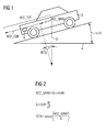
- a vehicle preferably a motor vehicle 2 ( figure 1 ) drives on a road which comprises a slope TETA.
- the motor vehicle 2 drives in direction down the road.
- a force which affects the motor vehicle in longitudinal direction of the motor vehicle may be given by a mass of the motor vehicle 2 times a total acceleration ACC_TOT.
- a first component ACC_VEH of the total acceleration ACC_TOT may be caused by a change of the speed of the motor vehicle 2.
- the speed of the motor vehicle 2 may be determined dependent on a speed of at least one wheel of the motor vehicle 2.
- the first component ACC_VEH of the total acceleration ACC_TOT is determined dependent on the change of the speed of the motor vehicle 2, for example by differentiating the speed of the motor vehicle 2.
- a second component ACC_GRAV of the total acceleration ACC_TOT may be caused by gravity.
- Gravity affects the motor vehicle 2 with the gravitational acceleration G perpendicular to a horizontal 4. Because the road comprises the slope TETA a component of the gravity affects the motor vehicle 2 in longitudinal direction of the motor vehicle 2. This component of gravity represents the second component ACC_GRAV of the total acceleration ACC_TOT.
- the slope TETA of the road may be dynamically determined according to the functions in Figure 2 .
- a device 6 for dynamically determining the slope TETA of the road is arranged in the motor vehicle 2 ( figur 4 ).
- the device 6 for dynamically determining the slope TETA of the road may be an independent device 6 or may be integrated into another device of the motor vehicle 2. If the device 6 for dynamically determining the slope TETA of the road is independent, the device 6 for dynamically determining the slope TETA of the road preferably comprises a central processing unit 8 and a memory 10. Further, the device 6 for dynamically determining the slope TETA may be electrically coupled to an acceleration sensor 12 which enables to measure the total acceleration ACC_TOT of the motor vehicle 2, for example an accelerometer.
- the device 6 for dynamically determining the slope TETA may be electrically coupled to a sensor which enables to determine the speed of the motor vehicle 2.
- the sensor for determining the speed of the motor vehicle is a wheel speed sensor 14. If the device 6 for dynamically determining the slope TETA is integrated into the other device, it may use a memory and/or a central processing unit of the other device.
- the speed of the motor vehicle 2 and, in particular, the speed of the wheels of the motor vehicle 2 may be provided by a further device of the motor vehicle 2, for example by an ABS-Device.
- the acceleration sensor 12 is arranged in such a way that a sensitive axis of the acceleration sensor 12 is parallel to the longitudinal axis of the motor vehicle 12.
- the acceleration sensor 12 may be arranged in such a way that the sensitive axis of the acceleration sensor 12 is between the longitudinal axis of the motor vehicle 2 and the vertical axis of the motor vehicle 2.
- the orientation of the sensitive axis of the acceleration sensor 12 has to be considered by dynamically determining the slope of the road.
- Another possibility may be to use an accelerometer with two or three sensitive axis. This would increase the accuracy of determining the slope and would enable to mount the device in any position.
- the position of the acceleration sensor 12 with two or more sensitive axis also has to be considered by determining the slope of the road.
- a program ( figure 3 ) for dynamically determining the slope TETA of the road is preferably stored on the memory 10 of the device 6 for dynamically determining the slope TETA.
- the program for dynamically determining the slope TETA is started in a step S1 in which, in case, variables are initialized.
- the total acceleration ACC_TOT is determined.
- the total acceleration ACC_TOT is determined by the accelerometer.
- a sensitive axis of the accelerometer is parallel to the longitudinal axis of the motor vehicle 2.
- the sensitive axis of the accelerometer may include a given angle with the longitudinal axis of the motor vehicle 2. However, that angle has to be considered by determining the slope TETA of the road.
- the first component ACC_VEH of the total acceleration ACC_TOT is determined.
- the first component ACC_VEH of the total acceleration ACC_TOT is determined by determining the speed of the motor vehicle 2 and by differentiating the speed of the motor vehicle 2.
- a step S4 the second component ACC_GRAV of the total acceleration ACC_TOT is determined dependent on the total acceleration ACC_TOT and dependent on the first component ACC_VEH of the total acceleration ACC_TOT.
- the second component ACC_GRAV of the total acceleration ACC_TOT is determined according to the function of the step S4.
- a step S5 the slope TETA of the road is determined dependent on the second component ACC_GRAV of the total acceleration ACC_TOT and dependent on the gravitational constant G.
- the slope TETA of the road is determined according to the functions of Figure 2 .
- a step S6 the program for dynamically determining the slope TETA of the road may be finished.
- the program for dynamically determining the slope TETA of the road is carried out regularly during the use of the motor vehicle 2.
- the program for dynamically determining the slope TETA of the road enables a dynamic determination of the slope TETA of the road in a very precise way.
- Dynamic means in this context that the slope TETA of the road may be determined while the motor vehicle 2 is driving and while the motor vehicle 2 changes its speed.
- the slope TETA may be determined differently by using a digital road map with slope information and/or a database, by using altitude information, in particular, information about the change of the altitude of the motor vehicle 2, by using a gyroscope and/or a tilt sensor.
- the altitude information may be gained by an ambient air pressure and/or by GPS.
- the motor vehicle 2 may be a different vehicle, for example a lorry or a bicycle.
- the program for determining the slope TETA of the road maybe implemented in a further program.
Landscapes
- Engineering & Computer Science (AREA)
- Radar, Positioning & Navigation (AREA)
- Remote Sensing (AREA)
- Physics & Mathematics (AREA)
- Automation & Control Theory (AREA)
- General Physics & Mathematics (AREA)
- Mathematical Physics (AREA)
- Transportation (AREA)
- Mechanical Engineering (AREA)
- Control Of Driving Devices And Active Controlling Of Vehicle (AREA)
- Electric Propulsion And Braking For Vehicles (AREA)
- Traffic Control Systems (AREA)
- Navigation (AREA)
- Investigating Or Analysing Materials By Optical Means (AREA)
Abstract
Description
- The invention relates to a method and a device for dynamically determining a slope of a road. The slope of the road is determined dependent on the gravity which affects a vehicle.
- For various applications in a modern vehicle, in particular in a motor vehicle it is beneficial to know a slope of a road where the motor vehicle is driving. These applications comprise for example a navigation system and/or an advanced driver assistance system. Slopes of roads are usually rather small. For determining the slope properly, an accuracy of approximately 1% slope is required. This is equivalent to an angle of about 0.6 degrees to a horizontal.
- There are various possibilities known to determine the slope of the road on which the motor vehicle is driving. For example a digital road map and/or a data base may contain slope information. Further, a gyroscope and/or a tilt sensor may contribute to determine the pitch of the motor vehicle which may contribute to determine the slope of the road. Further, the slope of the road may be determined dependent on an absolute change of an altitude in which the motor vehicle drives on the road. Such altitude information may be gained by an ambient air pressure and/or by GPS, in particular, by a Doppler shift of the GPS-Signal.
- The object of the present invention is to create a method and a device for determining a slope of a road which enables a dynamic and precise determining of the slope in an easy way.
- The object of the invention is achieved by the subject matter of
independent claims 1 and 6. Advantageous embodiments are given in the sub claims. - The invention is distinguished by a method and a device for dynamically determining a slope of a road. For dynamically determining the slope of the road a total acceleration which affects a vehicle on the road in longitudinal direction of the vehicle is measured. A first component of the total acceleration of the vehicle which is caused by a change of a speed of the vehicle is determined. A second component of the total acceleration of the vehicle which is caused by the gravity affecting the vehicle in longitudinal direction of the vehicle is determined. The second component is determined dependent on the total acceleration and dependent on the first component of the total acceleration. The slope of the road is determined dependent on the second component of the total acceleration.
- This enables to determine the slope of the road while the vehicle is driving on the road in a very easy and precise way. So, this enables a dynamic and precise determination of the slope of the road in an easy way. In other words: the slope is dynamically determined. The knowledge of the slope of the road may contribute to increase the safety for the vehicle, in particular for a motor vehicle on the road and/or may help the driver of the motor vehicle to navigate with the motor vehicle.
- In an advantageous embodiment of the invention the second component of the total acceleration is determined by subtracting the first component of the total acceleration from the total acceleration. This enables to determine the second component of the total acceleration in a very simple way.
- In a further advantageous embodiment of the invention the slope is determined by dividing a norm of the second component through a gravitational constant and by determining the arcsine of that division. This enables to determine the slope of the road in a very simple way.
- In a further advantageous embodiment of the invention a change of a speed of at least one wheel of the vehicle is determined and the first component of the total acceleration is determined dependent on the determined change of speed of the wheel. This contributes to determine the first component of the total acceleration of the vehicle in a very easy way.
- In a further advantageous embodiment of the invention a sensor for determining the total acceleration of the vehicle is calibrated dependent on GPS information and/or dependent on a digitalized road map and/or a database which contains the slope of the road and/or dependent on an ambient air pressure. This contributes to determine the slope of the road very precisely over a long time.
- The advantageous embodiments of the method may be transferred to advantageous embodiments of the device without any limitations. Further, the device at least comprises an acceleration sensor for measuring the total acceleration, a sensor for measuring at least one parameter which enables to determine the first component of the total acceleration, and at least one processor for determining the second component of the total acceleration and for determining the slope of the road.
- The invention is explained in the following with the aid of schematic drawings.
- These are as follows:
- figure 1
- a motor vehicle on a road with a slope,
- figure 2
- functions for determining the slope of the road,
- figure 3
- a float chart of a program for determining the slope of the road,
- figure 4
- a device for determining the slope of the road.
- Elements of the same design or function that appear in the different illustrations are identified by the same reference characters.
- A vehicle, preferably a motor vehicle 2 (
figure 1 ) drives on a road which comprises a slope TETA. For example, themotor vehicle 2 drives in direction down the road. A force which affects the motor vehicle in longitudinal direction of the motor vehicle may be given by a mass of themotor vehicle 2 times a total acceleration ACC_TOT. - A first component ACC_VEH of the total acceleration ACC_TOT may be caused by a change of the speed of the
motor vehicle 2. For example, the speed of themotor vehicle 2 may be determined dependent on a speed of at least one wheel of themotor vehicle 2. The first component ACC_VEH of the total acceleration ACC_TOT is determined dependent on the change of the speed of themotor vehicle 2, for example by differentiating the speed of themotor vehicle 2. - A second component ACC_GRAV of the total acceleration ACC_TOT may be caused by gravity. Gravity affects the
motor vehicle 2 with the gravitational acceleration G perpendicular to a horizontal 4. Because the road comprises the slope TETA a component of the gravity affects themotor vehicle 2 in longitudinal direction of themotor vehicle 2. This component of gravity represents the second component ACC_GRAV of the total acceleration ACC_TOT. - If the total acceleration ACC_TOT and the first component ACC_VEH of the total acceleration ACC_TOT are known, the slope TETA of the road may be dynamically determined according to the functions in
Figure 2 . - Preferably, a
device 6 for dynamically determining the slope TETA of the road is arranged in the motor vehicle 2 (figur 4 ). Thedevice 6 for dynamically determining the slope TETA of the road may be anindependent device 6 or may be integrated into another device of themotor vehicle 2. If thedevice 6 for dynamically determining the slope TETA of the road is independent, thedevice 6 for dynamically determining the slope TETA of the road preferably comprises acentral processing unit 8 and amemory 10. Further, thedevice 6 for dynamically determining the slope TETA may be electrically coupled to anacceleration sensor 12 which enables to measure the total acceleration ACC_TOT of themotor vehicle 2, for example an accelerometer. Further, thedevice 6 for dynamically determining the slope TETA may be electrically coupled to a sensor which enables to determine the speed of themotor vehicle 2. Preferably, the sensor for determining the speed of the motor vehicle is awheel speed sensor 14. If thedevice 6 for dynamically determining the slope TETA is integrated into the other device, it may use a memory and/or a central processing unit of the other device. Further, the speed of themotor vehicle 2 and, in particular, the speed of the wheels of themotor vehicle 2 may be provided by a further device of themotor vehicle 2, for example by an ABS-Device. - Preferably, the
acceleration sensor 12 is arranged in such a way that a sensitive axis of theacceleration sensor 12 is parallel to the longitudinal axis of themotor vehicle 12. Alternatively, theacceleration sensor 12 may be arranged in such a way that the sensitive axis of theacceleration sensor 12 is between the longitudinal axis of themotor vehicle 2 and the vertical axis of themotor vehicle 2. In any case, the orientation of the sensitive axis of theacceleration sensor 12 has to be considered by dynamically determining the slope of the road. Another possibility may be to use an accelerometer with two or three sensitive axis. This would increase the accuracy of determining the slope and would enable to mount the device in any position. However, the position of theacceleration sensor 12 with two or more sensitive axis also has to be considered by determining the slope of the road. - A program (
figure 3 ) for dynamically determining the slope TETA of the road is preferably stored on thememory 10 of thedevice 6 for dynamically determining the slope TETA. The program for dynamically determining the slope TETA is started in a step S1 in which, in case, variables are initialized. - In a step S2 the total acceleration ACC_TOT is determined. Preferably, the total acceleration ACC_TOT is determined by the accelerometer. Preferably, a sensitive axis of the accelerometer is parallel to the longitudinal axis of the
motor vehicle 2. Alternatively, the sensitive axis of the accelerometer may include a given angle with the longitudinal axis of themotor vehicle 2. However, that angle has to be considered by determining the slope TETA of the road. - In a step S3 the first component ACC_VEH of the total acceleration ACC_TOT is determined. Preferably, the first component ACC_VEH of the total acceleration ACC_TOT is determined by determining the speed of the
motor vehicle 2 and by differentiating the speed of themotor vehicle 2. - In a step S4 the second component ACC_GRAV of the total acceleration ACC_TOT is determined dependent on the total acceleration ACC_TOT and dependent on the first component ACC_VEH of the total acceleration ACC_TOT. Preferably, the second component ACC_GRAV of the total acceleration ACC_TOT is determined according to the function of the step S4.
- In a step S5 the slope TETA of the road is determined dependent on the second component ACC_GRAV of the total acceleration ACC_TOT and dependent on the gravitational constant G. Preferably, the slope TETA of the road is determined according to the functions of
Figure 2 . - In a step S6 the program for dynamically determining the slope TETA of the road may be finished. Preferably, the program for dynamically determining the slope TETA of the road is carried out regularly during the use of the
motor vehicle 2. - The program for dynamically determining the slope TETA of the road enables a dynamic determination of the slope TETA of the road in a very precise way. Dynamic means in this context that the slope TETA of the road may be determined while the
motor vehicle 2 is driving and while themotor vehicle 2 changes its speed. - In order to determine the slope TETA very precisely over a long time, it is advantageous to calibrate the
device 6 for determining the slope TETA regularly. For this reason, the slope TETA is determined differently, the results are compared, and thedevice 6 for determining the slope TETA is calibrated according to that comparison. The slope TETA may be determined differently by using a digital road map with slope information and/or a database, by using altitude information, in particular, information about the change of the altitude of themotor vehicle 2, by using a gyroscope and/or a tilt sensor. The altitude information may be gained by an ambient air pressure and/or by GPS. - The invention is not restricted on the explained embodiment. For example, the
motor vehicle 2 may be a different vehicle, for example a lorry or a bicycle. Further, the program for determining the slope TETA of the road maybe implemented in a further program. -
- 2
- vehicle
- 4
- horizontal
- 6
- device
- 8
- central processing unit
- 10
- memory
- 12
- acceleration sensor
- 14
- wheel speed sensor
- TETA
- slope
- G
- gravitational constant
- ACC_TOT
- total acceleration
- ACC_GRAV
- second component
- ACC_VEH
- first component
- START
- Start
- END
- End
- S1 - S6
- steps one to six
Claims (6)
- Method for dynamically determining a slope (TETA) of a road comprising the steps of:- measuring a total acceleration (ACC_TOT) which affects a vehicle on the road in longitudinal direction of the vehicle,- determining a first component (ACC_VEH) of the total acceleration (ACC_TOT) of the vehicle which is caused by a change of a speed of the vehicle,- determining a second component (ACC_GRAV) of the total acceleration (ACC_TOT) of the vehicle which is caused by the gravity affecting the vehicle in longitudinal direction of the vehicle dependent on the total acceleration (ACC_TOT) and dependent on the first component (ACC_VEH) of the total acceleration (ACC_TOT),- determining the slope (TETA) of the road dependent on the second component (ACC_GRAV) of the total acceleration (ACC_TOT).
- Method in accordance with claim 1 with the second component (ACC_GRAV) of the total acceleration (ACC_TOT) being determined by subtracting the first component (ACC_VEH) of the total acceleration (ACC_TOT) from the total acceleration (ACC_TOT).
- Method in accordance with one of the preceding claims with the slope (TETA) being determined by dividing a norm of the second component (ACC_GRAV) through a gravitational constant (G) and by determining the arc sine of that division.
- Method in accordance with one of the preceding claims comprising the steps of determining a change of a speed of at least one wheel of the vehicle and of determining the first component (ACC_VEH) of the total acceleration dependent (ACC_TOT) on the determined change of the speed of the wheel.
- Method in accordance with one of the preceding claims with a sensor for determining the total acceleration (ACC_TOT) of the vehicle being calibrated dependent on GPS-Information and/or dependent on a digitalized road map which contains the slope (TETA) of the road and/or dependent on an ambient air pressure.
- Device for dynamically determining a slope (TETA) of a road which is arranged for:- measuring a total acceleration (ACC_TOT) which affects a vehicle on the road in longitudinal direction of the vehicle,- determining a first component (ACC_VEH) of the total acceleration (ACC_TOT) of the vehicle which is caused by a change of a speed of the vehicle,- determining a second component (ACC_GRAV) of the total acceleration (ACC_TOT) of the vehicle which is caused by the gravity affecting the vehicle in longitudinal direction of the vehicle dependent on the total acceleration (ACC_TOT) and dependent on the first component (ACC_VEH) of the total acceleration (ACC_TOT),- determining the slope (TETA) of the road dependent on the second component (ACC_GRAV) of the total acceleration (ACC_TOT).
Priority Applications (3)
| Application Number | Priority Date | Filing Date | Title |
|---|---|---|---|
| AT06025364T ATE428905T1 (en) | 2006-12-07 | 2006-12-07 | METHOD AND DEVICE FOR DYNAMIC DETERMINATION OF THE ROAD INCLINATION |
| EP06025364A EP1930690B1 (en) | 2006-12-07 | 2006-12-07 | Method and device for dynamically determining a slope of a road |
| DE602006006322T DE602006006322D1 (en) | 2006-12-07 | 2006-12-07 | Method and device for the dynamic determination of road gradient |
Applications Claiming Priority (1)
| Application Number | Priority Date | Filing Date | Title |
|---|---|---|---|
| EP06025364A EP1930690B1 (en) | 2006-12-07 | 2006-12-07 | Method and device for dynamically determining a slope of a road |
Publications (2)
| Publication Number | Publication Date |
|---|---|
| EP1930690A1 true EP1930690A1 (en) | 2008-06-11 |
| EP1930690B1 EP1930690B1 (en) | 2009-04-15 |
Family
ID=37692422
Family Applications (1)
| Application Number | Title | Priority Date | Filing Date |
|---|---|---|---|
| EP06025364A Not-in-force EP1930690B1 (en) | 2006-12-07 | 2006-12-07 | Method and device for dynamically determining a slope of a road |
Country Status (3)
| Country | Link |
|---|---|
| EP (1) | EP1930690B1 (en) |
| AT (1) | ATE428905T1 (en) |
| DE (1) | DE602006006322D1 (en) |
Cited By (8)
| Publication number | Priority date | Publication date | Assignee | Title |
|---|---|---|---|---|
| WO2010139493A1 (en) * | 2009-06-03 | 2010-12-09 | Zf Friedrichshafen Ag | Method for calibrating a slope sensor |
| EP2529976A3 (en) * | 2011-06-03 | 2013-02-27 | Koito Manufacturing Co., Ltd. | Vehicle lamp control device and vehicle lamp system |
| EP2963385A1 (en) * | 2014-07-03 | 2016-01-06 | Memsic, Inc. | Method and apparatus for determining the inclination of a moving vehicle with respect to the road and for performing dynamic headlight leveling |
| CN104590272B (en) * | 2014-12-23 | 2017-04-12 | 安徽江淮汽车集团股份有限公司 | Method and system for detecting ramp state of vehicle |
| DE102017211376A1 (en) * | 2017-07-04 | 2019-01-10 | Zf Friedrichshafen Ag | Method and control device for determining an inclination of a vehicle in the direction of travel |
| US20220041167A1 (en) * | 2018-10-10 | 2022-02-10 | Sony Corporation | Information processing apparatus, mobile apparatus, method, and program |
| CN114222852A (en) * | 2021-02-02 | 2022-03-22 | 浙江吉利控股集团有限公司 | Engine control method, device and system and vehicle |
| IT202200012973A1 (en) * | 2022-06-20 | 2023-12-20 | Cnh Ind Italia Spa | IMPROVED WORK VEHICLE AND RELATED CONTROL METHOD |
Families Citing this family (2)
| Publication number | Priority date | Publication date | Assignee | Title |
|---|---|---|---|---|
| CN105116167A (en) * | 2015-09-10 | 2015-12-02 | 深圳威易森科技有限公司 | Acceleration determination method for motor vehicle running on slope plane |
| CN110409264B (en) * | 2019-07-29 | 2021-05-07 | 中煤第三建设(集团)有限责任公司 | Equipment for detecting road surface inclination angle by paving road bridge |
Citations (3)
| Publication number | Priority date | Publication date | Assignee | Title |
|---|---|---|---|---|
| DE3933652A1 (en) * | 1989-10-09 | 1991-04-11 | Bosch Gmbh Robert | ANTI-BLOCKING CONTROL SYSTEM AND DRIVE-SLIP CONTROL SYSTEM |
| EP0901929A1 (en) * | 1997-09-10 | 1999-03-17 | Fuji Jukogyo Kabushiki Kaisha | Vehicle maneuvering control device |
| FR2857925A1 (en) * | 2003-07-22 | 2005-01-28 | Delphi Tech Inc | Surface slope estimating method for motor vehicle, involves producing quantitative estimation signal of slope when frost condition for slope measurement is verified and congealing estimation signal when frost condition is verified |
Family Cites Families (1)
| Publication number | Priority date | Publication date | Assignee | Title |
|---|---|---|---|---|
| DE10154341A1 (en) * | 2001-11-06 | 2003-05-15 | Volkswagen Ag | Method and device for determining a geometric inclination of a motor vehicle |
-
2006
- 2006-12-07 EP EP06025364A patent/EP1930690B1/en not_active Not-in-force
- 2006-12-07 AT AT06025364T patent/ATE428905T1/en not_active IP Right Cessation
- 2006-12-07 DE DE602006006322T patent/DE602006006322D1/en active Active
Patent Citations (3)
| Publication number | Priority date | Publication date | Assignee | Title |
|---|---|---|---|---|
| DE3933652A1 (en) * | 1989-10-09 | 1991-04-11 | Bosch Gmbh Robert | ANTI-BLOCKING CONTROL SYSTEM AND DRIVE-SLIP CONTROL SYSTEM |
| EP0901929A1 (en) * | 1997-09-10 | 1999-03-17 | Fuji Jukogyo Kabushiki Kaisha | Vehicle maneuvering control device |
| FR2857925A1 (en) * | 2003-07-22 | 2005-01-28 | Delphi Tech Inc | Surface slope estimating method for motor vehicle, involves producing quantitative estimation signal of slope when frost condition for slope measurement is verified and congealing estimation signal when frost condition is verified |
Cited By (17)
| Publication number | Priority date | Publication date | Assignee | Title |
|---|---|---|---|---|
| CN102458955A (en) * | 2009-06-03 | 2012-05-16 | Zf腓德烈斯哈芬股份公司 | Method for calibrating an inclination sensor |
| US8386123B2 (en) | 2009-06-03 | 2013-02-26 | Zf Friedrichshafen Ag | Method for calibrating a slope sensor |
| CN102458955B (en) * | 2009-06-03 | 2014-09-10 | Zf腓德烈斯哈芬股份公司 | Method for calibrating a slope sensor |
| WO2010139493A1 (en) * | 2009-06-03 | 2010-12-09 | Zf Friedrichshafen Ag | Method for calibrating a slope sensor |
| EP2529976A3 (en) * | 2011-06-03 | 2013-02-27 | Koito Manufacturing Co., Ltd. | Vehicle lamp control device and vehicle lamp system |
| US9067533B2 (en) | 2011-06-03 | 2015-06-30 | Koito Manufacturing Co., Ltd. | Vehicle lamp control device and vehicle lamp system |
| CN105291958B (en) * | 2014-07-03 | 2017-08-25 | 美新半导体(无锡)有限公司 | The method and apparatus that Mechatronic Systems is controlled relative to the inclination angle of road based on vehicle |
| EP2963385A1 (en) * | 2014-07-03 | 2016-01-06 | Memsic, Inc. | Method and apparatus for determining the inclination of a moving vehicle with respect to the road and for performing dynamic headlight leveling |
| CN105291958A (en) * | 2014-07-03 | 2016-02-03 | 美新半导体(无锡)有限公司 | Method and apparatus for determining the inclination of a moving vehicle with respect to the road |
| CN104590272B (en) * | 2014-12-23 | 2017-04-12 | 安徽江淮汽车集团股份有限公司 | Method and system for detecting ramp state of vehicle |
| DE102017211376A1 (en) * | 2017-07-04 | 2019-01-10 | Zf Friedrichshafen Ag | Method and control device for determining an inclination of a vehicle in the direction of travel |
| US20220041167A1 (en) * | 2018-10-10 | 2022-02-10 | Sony Corporation | Information processing apparatus, mobile apparatus, method, and program |
| CN114222852A (en) * | 2021-02-02 | 2022-03-22 | 浙江吉利控股集团有限公司 | Engine control method, device and system and vehicle |
| EP4063211A4 (en) * | 2021-02-02 | 2022-11-02 | Zhejiang Geely Holding Group Co., Ltd. | ENGINE CONTROL METHOD, APPARATUS AND SYSTEM, AND VEHICLE |
| KR20230084574A (en) * | 2021-02-02 | 2023-06-13 | 쩌지앙 길리 홀딩 그룹 씨오., 엘티디. | Engine control method, device, system and vehicle |
| CN114222852B (en) * | 2021-02-02 | 2024-07-23 | 浙江吉利控股集团有限公司 | Engine control method, device, system and vehicle |
| IT202200012973A1 (en) * | 2022-06-20 | 2023-12-20 | Cnh Ind Italia Spa | IMPROVED WORK VEHICLE AND RELATED CONTROL METHOD |
Also Published As
| Publication number | Publication date |
|---|---|
| ATE428905T1 (en) | 2009-05-15 |
| EP1930690B1 (en) | 2009-04-15 |
| DE602006006322D1 (en) | 2009-05-28 |
Similar Documents
| Publication | Publication Date | Title |
|---|---|---|
| EP1722239B1 (en) | Apparatus and method for measuring speed of a moving object | |
| JP7036080B2 (en) | Inertial navigation system | |
| US7463953B1 (en) | Method for determining a tilt angle of a vehicle | |
| US8731769B2 (en) | Inertial sensor calibration method for vehicles and device therefor | |
| RU2591018C2 (en) | Method for calibration of inertial sensor installed in arbitrary position on board vehicle, and sensor system for dynamic parameters of vehicle adapted to be arranged in arbitrary position onboard | |
| CN107560612B (en) | Method and device for determining the angular position of a vehicle | |
| KR970011786A (en) | Apparatus and method for tracking vehicles | |
| US20180154902A1 (en) | Vehicle control using road angle data | |
| JP2009276109A (en) | Device and method for measuring gradient in road | |
| CN108051839B (en) | Vehicle-mounted three-dimensional positioning device and three-dimensional positioning method | |
| CN101576387B (en) | Navigation information correction method and navigation device thereof | |
| JP3804409B2 (en) | Processing device using acceleration | |
| EP1930690A1 (en) | Method and device for dynamically determining a slope of a road | |
| US20080269976A1 (en) | Control System for Vehicles | |
| US20110197414A1 (en) | Sensor arrangement and method for easy installation into a vehicle | |
| US7058486B2 (en) | Method and device for determining the float angle of a motor vehicle | |
| US20220073041A1 (en) | Method for the Traction Control of a Single-Track Motor Vehicle Taking the Slip Angle of the Rear Wheel Into Consideration | |
| US9605958B2 (en) | Method and device for determining the inclined position of a vehicle | |
| CN112429006A (en) | Vehicle-mounted road surface gradient measuring system and measuring method | |
| Weinberg | MEMS sensors are driving the automotive industry.(Putting sensors to work) | |
| JP2005274186A (en) | Acceleration calculation method of navigation device | |
| JP2006227019A (en) | Processing device using acceleration | |
| US9791277B2 (en) | Apparatus and method for measuring velocity of moving object in a navigation system | |
| CN110967023A (en) | Automobile positioning method and automobile positioning device | |
| KR102330172B1 (en) | Braking distance test apparatus and an operating method thereof |
Legal Events
| Date | Code | Title | Description |
|---|---|---|---|
| PUAI | Public reference made under article 153(3) epc to a published international application that has entered the european phase |
Free format text: ORIGINAL CODE: 0009012 |
|
| 17P | Request for examination filed |
Effective date: 20070709 |
|
| AK | Designated contracting states |
Kind code of ref document: A1 Designated state(s): AT BE BG CH CY CZ DE DK EE ES FI FR GB GR HU IE IS IT LI LT LU LV MC NL PL PT RO SE SI SK TR |
|
| AX | Request for extension of the european patent |
Extension state: AL BA HR MK RS |
|
| GRAP | Despatch of communication of intention to grant a patent |
Free format text: ORIGINAL CODE: EPIDOSNIGR1 |
|
| GRAP | Despatch of communication of intention to grant a patent |
Free format text: ORIGINAL CODE: EPIDOSNIGR1 |
|
| AKX | Designation fees paid |
Designated state(s): AT BE BG CH CY CZ DE DK EE ES FI FR GB GR HU IE IS IT LI LT LU LV MC NL PL PT RO SE SI SK TR |
|
| GRAS | Grant fee paid |
Free format text: ORIGINAL CODE: EPIDOSNIGR3 |
|
| GRAA | (expected) grant |
Free format text: ORIGINAL CODE: 0009210 |
|
| AK | Designated contracting states |
Kind code of ref document: B1 Designated state(s): AT BE BG CH CY CZ DE DK EE ES FI FR GB GR HU IE IS IT LI LT LU LV MC NL PL PT RO SE SI SK TR |
|
| REG | Reference to a national code |
Ref country code: GB Ref legal event code: FG4D Ref country code: CH Ref legal event code: EP |
|
| REG | Reference to a national code |
Ref country code: IE Ref legal event code: FG4D |
|
| REF | Corresponds to: |
Ref document number: 602006006322 Country of ref document: DE Date of ref document: 20090528 Kind code of ref document: P |
|
| NLV1 | Nl: lapsed or annulled due to failure to fulfill the requirements of art. 29p and 29m of the patents act | ||
| PG25 | Lapsed in a contracting state [announced via postgrant information from national office to epo] |
Ref country code: PT Free format text: LAPSE BECAUSE OF FAILURE TO SUBMIT A TRANSLATION OF THE DESCRIPTION OR TO PAY THE FEE WITHIN THE PRESCRIBED TIME-LIMIT Effective date: 20090915 Ref country code: LT Free format text: LAPSE BECAUSE OF FAILURE TO SUBMIT A TRANSLATION OF THE DESCRIPTION OR TO PAY THE FEE WITHIN THE PRESCRIBED TIME-LIMIT Effective date: 20090415 Ref country code: ES Free format text: LAPSE BECAUSE OF FAILURE TO SUBMIT A TRANSLATION OF THE DESCRIPTION OR TO PAY THE FEE WITHIN THE PRESCRIBED TIME-LIMIT Effective date: 20090726 Ref country code: FI Free format text: LAPSE BECAUSE OF FAILURE TO SUBMIT A TRANSLATION OF THE DESCRIPTION OR TO PAY THE FEE WITHIN THE PRESCRIBED TIME-LIMIT Effective date: 20090415 Ref country code: AT Free format text: LAPSE BECAUSE OF FAILURE TO SUBMIT A TRANSLATION OF THE DESCRIPTION OR TO PAY THE FEE WITHIN THE PRESCRIBED TIME-LIMIT Effective date: 20090415 |
|
| PG25 | Lapsed in a contracting state [announced via postgrant information from national office to epo] |
Ref country code: IS Free format text: LAPSE BECAUSE OF FAILURE TO SUBMIT A TRANSLATION OF THE DESCRIPTION OR TO PAY THE FEE WITHIN THE PRESCRIBED TIME-LIMIT Effective date: 20090815 Ref country code: LV Free format text: LAPSE BECAUSE OF FAILURE TO SUBMIT A TRANSLATION OF THE DESCRIPTION OR TO PAY THE FEE WITHIN THE PRESCRIBED TIME-LIMIT Effective date: 20090415 Ref country code: PL Free format text: LAPSE BECAUSE OF FAILURE TO SUBMIT A TRANSLATION OF THE DESCRIPTION OR TO PAY THE FEE WITHIN THE PRESCRIBED TIME-LIMIT Effective date: 20090415 Ref country code: NL Free format text: LAPSE BECAUSE OF FAILURE TO SUBMIT A TRANSLATION OF THE DESCRIPTION OR TO PAY THE FEE WITHIN THE PRESCRIBED TIME-LIMIT Effective date: 20090415 Ref country code: SE Free format text: LAPSE BECAUSE OF FAILURE TO SUBMIT A TRANSLATION OF THE DESCRIPTION OR TO PAY THE FEE WITHIN THE PRESCRIBED TIME-LIMIT Effective date: 20090715 Ref country code: SI Free format text: LAPSE BECAUSE OF FAILURE TO SUBMIT A TRANSLATION OF THE DESCRIPTION OR TO PAY THE FEE WITHIN THE PRESCRIBED TIME-LIMIT Effective date: 20090415 |
|
| PG25 | Lapsed in a contracting state [announced via postgrant information from national office to epo] |
Ref country code: RO Free format text: LAPSE BECAUSE OF FAILURE TO SUBMIT A TRANSLATION OF THE DESCRIPTION OR TO PAY THE FEE WITHIN THE PRESCRIBED TIME-LIMIT Effective date: 20090415 Ref country code: DK Free format text: LAPSE BECAUSE OF FAILURE TO SUBMIT A TRANSLATION OF THE DESCRIPTION OR TO PAY THE FEE WITHIN THE PRESCRIBED TIME-LIMIT Effective date: 20090415 Ref country code: CZ Free format text: LAPSE BECAUSE OF FAILURE TO SUBMIT A TRANSLATION OF THE DESCRIPTION OR TO PAY THE FEE WITHIN THE PRESCRIBED TIME-LIMIT Effective date: 20090415 Ref country code: EE Free format text: LAPSE BECAUSE OF FAILURE TO SUBMIT A TRANSLATION OF THE DESCRIPTION OR TO PAY THE FEE WITHIN THE PRESCRIBED TIME-LIMIT Effective date: 20090415 |
|
| PLBE | No opposition filed within time limit |
Free format text: ORIGINAL CODE: 0009261 |
|
| STAA | Information on the status of an ep patent application or granted ep patent |
Free format text: STATUS: NO OPPOSITION FILED WITHIN TIME LIMIT |
|
| PG25 | Lapsed in a contracting state [announced via postgrant information from national office to epo] |
Ref country code: BE Free format text: LAPSE BECAUSE OF FAILURE TO SUBMIT A TRANSLATION OF THE DESCRIPTION OR TO PAY THE FEE WITHIN THE PRESCRIBED TIME-LIMIT Effective date: 20090415 Ref country code: SK Free format text: LAPSE BECAUSE OF FAILURE TO SUBMIT A TRANSLATION OF THE DESCRIPTION OR TO PAY THE FEE WITHIN THE PRESCRIBED TIME-LIMIT Effective date: 20090415 |
|
| 26N | No opposition filed |
Effective date: 20100118 |
|
| PG25 | Lapsed in a contracting state [announced via postgrant information from national office to epo] |
Ref country code: BG Free format text: LAPSE BECAUSE OF FAILURE TO SUBMIT A TRANSLATION OF THE DESCRIPTION OR TO PAY THE FEE WITHIN THE PRESCRIBED TIME-LIMIT Effective date: 20090715 |
|
| PG25 | Lapsed in a contracting state [announced via postgrant information from national office to epo] |
Ref country code: MC Free format text: LAPSE BECAUSE OF NON-PAYMENT OF DUE FEES Effective date: 20100701 |
|
| REG | Reference to a national code |
Ref country code: FR Ref legal event code: ST Effective date: 20100831 |
|
| PG25 | Lapsed in a contracting state [announced via postgrant information from national office to epo] |
Ref country code: FR Free format text: LAPSE BECAUSE OF NON-PAYMENT OF DUE FEES Effective date: 20091231 Ref country code: GR Free format text: LAPSE BECAUSE OF FAILURE TO SUBMIT A TRANSLATION OF THE DESCRIPTION OR TO PAY THE FEE WITHIN THE PRESCRIBED TIME-LIMIT Effective date: 20090716 Ref country code: IE Free format text: LAPSE BECAUSE OF NON-PAYMENT OF DUE FEES Effective date: 20091207 |
|
| PG25 | Lapsed in a contracting state [announced via postgrant information from national office to epo] |
Ref country code: IT Free format text: LAPSE BECAUSE OF FAILURE TO SUBMIT A TRANSLATION OF THE DESCRIPTION OR TO PAY THE FEE WITHIN THE PRESCRIBED TIME-LIMIT Effective date: 20090415 |
|
| PG25 | Lapsed in a contracting state [announced via postgrant information from national office to epo] |
Ref country code: LU Free format text: LAPSE BECAUSE OF NON-PAYMENT OF DUE FEES Effective date: 20091207 |
|
| PG25 | Lapsed in a contracting state [announced via postgrant information from national office to epo] |
Ref country code: HU Free format text: LAPSE BECAUSE OF FAILURE TO SUBMIT A TRANSLATION OF THE DESCRIPTION OR TO PAY THE FEE WITHIN THE PRESCRIBED TIME-LIMIT Effective date: 20091016 |
|
| REG | Reference to a national code |
Ref country code: CH Ref legal event code: PL |
|
| PG25 | Lapsed in a contracting state [announced via postgrant information from national office to epo] |
Ref country code: TR Free format text: LAPSE BECAUSE OF FAILURE TO SUBMIT A TRANSLATION OF THE DESCRIPTION OR TO PAY THE FEE WITHIN THE PRESCRIBED TIME-LIMIT Effective date: 20090415 |
|
| PG25 | Lapsed in a contracting state [announced via postgrant information from national office to epo] |
Ref country code: CY Free format text: LAPSE BECAUSE OF FAILURE TO SUBMIT A TRANSLATION OF THE DESCRIPTION OR TO PAY THE FEE WITHIN THE PRESCRIBED TIME-LIMIT Effective date: 20090415 |
|
| PG25 | Lapsed in a contracting state [announced via postgrant information from national office to epo] |
Ref country code: LI Free format text: LAPSE BECAUSE OF NON-PAYMENT OF DUE FEES Effective date: 20101231 Ref country code: CH Free format text: LAPSE BECAUSE OF NON-PAYMENT OF DUE FEES Effective date: 20101231 |
|
| PGFP | Annual fee paid to national office [announced via postgrant information from national office to epo] |
Ref country code: GB Payment date: 20121220 Year of fee payment: 7 |
|
| GBPC | Gb: european patent ceased through non-payment of renewal fee |
Effective date: 20131207 |
|
| PG25 | Lapsed in a contracting state [announced via postgrant information from national office to epo] |
Ref country code: GB Free format text: LAPSE BECAUSE OF NON-PAYMENT OF DUE FEES Effective date: 20131207 |
|
| REG | Reference to a national code |
Ref country code: DE Ref legal event code: R084 Ref document number: 602006006322 Country of ref document: DE |
|
| REG | Reference to a national code |
Ref country code: DE Ref legal event code: R081 Ref document number: 602006006322 Country of ref document: DE Owner name: CONTINENTAL AUTOMOTIVE TECHNOLOGIES GMBH, DE Free format text: FORMER OWNER: CONTINENTAL AUTOMOTIVE GMBH, 30165 HANNOVER, DE |
|
| PGFP | Annual fee paid to national office [announced via postgrant information from national office to epo] |
Ref country code: DE Payment date: 20231231 Year of fee payment: 18 |
|
| REG | Reference to a national code |
Ref country code: DE Ref legal event code: R081 Ref document number: 602006006322 Country of ref document: DE Owner name: CONTINENTAL AUTOMOTIVE TECHNOLOGIES GMBH, DE Free format text: FORMER OWNER: CONTINENTAL AUTOMOTIVE TECHNOLOGIES GMBH, 30165 HANNOVER, DE |
|
| REG | Reference to a national code |
Ref country code: DE Ref legal event code: R119 Ref document number: 602006006322 Country of ref document: DE |
|
| PG25 | Lapsed in a contracting state [announced via postgrant information from national office to epo] |
Ref country code: DE Free format text: LAPSE BECAUSE OF NON-PAYMENT OF DUE FEES Effective date: 20250701 |