EP1930590A1 - Oscillation plate type compressor - Google Patents
Oscillation plate type compressor Download PDFInfo
- Publication number
- EP1930590A1 EP1930590A1 EP06781469A EP06781469A EP1930590A1 EP 1930590 A1 EP1930590 A1 EP 1930590A1 EP 06781469 A EP06781469 A EP 06781469A EP 06781469 A EP06781469 A EP 06781469A EP 1930590 A1 EP1930590 A1 EP 1930590A1
- Authority
- EP
- European Patent Office
- Prior art keywords
- piston
- connecting rod
- wobble plate
- precession
- circumferential surface
- Prior art date
- Legal status (The legal status is an assumption and is not a legal conclusion. Google has not performed a legal analysis and makes no representation as to the accuracy of the status listed.)
- Withdrawn
Links
Images


Classifications
-
- F—MECHANICAL ENGINEERING; LIGHTING; HEATING; WEAPONS; BLASTING
- F04—POSITIVE - DISPLACEMENT MACHINES FOR LIQUIDS; PUMPS FOR LIQUIDS OR ELASTIC FLUIDS
- F04B—POSITIVE-DISPLACEMENT MACHINES FOR LIQUIDS; PUMPS
- F04B27/00—Multi-cylinder pumps specially adapted for elastic fluids and characterised by number or arrangement of cylinders
- F04B27/08—Multi-cylinder pumps specially adapted for elastic fluids and characterised by number or arrangement of cylinders having cylinders coaxial with, or parallel or inclined to, main shaft axis
- F04B27/0873—Component parts, e.g. sealings; Manufacturing or assembly thereof
- F04B27/0878—Pistons
-
- F—MECHANICAL ENGINEERING; LIGHTING; HEATING; WEAPONS; BLASTING
- F04—POSITIVE - DISPLACEMENT MACHINES FOR LIQUIDS; PUMPS FOR LIQUIDS OR ELASTIC FLUIDS
- F04B—POSITIVE-DISPLACEMENT MACHINES FOR LIQUIDS; PUMPS
- F04B27/00—Multi-cylinder pumps specially adapted for elastic fluids and characterised by number or arrangement of cylinders
- F04B27/08—Multi-cylinder pumps specially adapted for elastic fluids and characterised by number or arrangement of cylinders having cylinders coaxial with, or parallel or inclined to, main shaft axis
- F04B27/0873—Component parts, e.g. sealings; Manufacturing or assembly thereof
- F04B27/0878—Pistons
- F04B27/0886—Piston shoes
-
- F—MECHANICAL ENGINEERING; LIGHTING; HEATING; WEAPONS; BLASTING
- F04—POSITIVE - DISPLACEMENT MACHINES FOR LIQUIDS; PUMPS FOR LIQUIDS OR ELASTIC FLUIDS
- F04B—POSITIVE-DISPLACEMENT MACHINES FOR LIQUIDS; PUMPS
- F04B27/00—Multi-cylinder pumps specially adapted for elastic fluids and characterised by number or arrangement of cylinders
- F04B27/08—Multi-cylinder pumps specially adapted for elastic fluids and characterised by number or arrangement of cylinders having cylinders coaxial with, or parallel or inclined to, main shaft axis
- F04B27/0873—Component parts, e.g. sealings; Manufacturing or assembly thereof
- F04B27/0895—Component parts, e.g. sealings; Manufacturing or assembly thereof driving means
Definitions
- the present invention relates to a wobble plate compressor.
- a wobble plate compressor comprising a main shaft driven by a power source, a wobble plate driven by the main shaft to swing, a piston connected to the wobble plate by a connecting rod, and a cylinder bore extending parallel to the main shaft to accept the piston is well known.
- the wobble plate compressor is equipped with a mechanism for preventing rotation of the wobble plate.
- Patent document 1 discloses a mechanism for preventing rotation of the wobble plate comprising a guide rod and a clamping member slidably engaging the guide rod.
- Patent document 2 discloses a mechanism for preventing rotation of the wobble plate comprising a pair of bevel gears engaging each other.
- Patent document 3 discloses a mechanism for preventing rotation of the wobble plate comprising a ball joint provided with a key and a key groove.
- Patent document 1 Japanese Patent Laid-Open Publication No. 5-10256
- Patent document 2 Japanese Patent Laid-Open Publication No. 5-33763
- Patent document 3 Japanese Patent Laid-Open Publication No.
- An object of the present invention is to provide a wobble plate compressor equipped with a mechanism for preventing the rotation of the wobble plate which is simply structured, producible at low cost, and does not cause heavy noise or vibration.
- a wobble plate compressor comprising a main shaft driven by a power source, a wobble plate driven by the main shaft to swing, a piston connected to the wobble plate by a connecting rod, and a cylinder bore extending parallel to the main shaft to accept the piston, wherein the connecting rod is connected to the wobble plate by a ball joint, precession of the connecting rod is allowed when the piston moves reciprocally, and the outer circumferential surface of the piston is forced against the inner circumferential surface of the cylinder bore when the wobble plate is driven by the main shaft to rotate and the connecting rod is driven by the rotating wobble plate to swing beyond the range of the precession, thereby preventing rotation of the wobble plate.
- the center of the ball joint connecting the connecting rod to the wobble plate reciprocally moves in the longitudinal direction of the main shaft and orbits with a small radius in the radial direction of the main shaft to cause precession of the connection rod. Therefore, allowance of the precession of the connecting rod enables smooth movement of the piston.
- the rotation of the wobble plate is transmitted to the connecting rod through the ball joint to cause swing of the connecting rod beyond the range of the precession.
- the connecting rod swings beyond the range of the precession, the outer circumferential surface of the piston is forced against the inner circumferential surface of the cylinder bore to prevent the swing of the connecting rod.
- the rotation of the wobble plate is prevented.
- the mechanism for allowing the precession of the connecting rod and forcing the outer circumferential surface of the piston against the inner circumferential surface of the cylinder bore when the connecting rod swings beyond the range of the precession can be structured simply and produced at low cost.
- Prevention of rotation of the wobble plate causes no heavy noise or vibration because the rotation of the wobble plate is prevented by forcing the outer circumferential surface of the piston against the inner circumferential surface of the cylinder bore. Therefore, the present invention can provide a wobble plate compressor equipped with a mechanism for preventing the rotation of the wobble plate which is simply structured, producible at low cost, and does not cause heavy noise or vibration.
- the connecting rod is connected to the piston by a ball joint, a radial space is formed between the piston and the connecting rod to allow the precession of the connecting rod when the piston moves reciprocally, and the connecting rod abuts the piston to force it when the connecting rod is driven by the rotating wobble plate to swing beyond the range of the precession, thereby forcing the outer circumferential surface of the piston against the inner circumferential surface of the cylinder bore.
- the connecting rod is connected to the piston by a pin, a radial space is formed between the piston and the connecting rod to allow the precession of the connecting rod when the piston moves reciprocally, and the connecting rod abuts the piston to force it when the connecting rod is driven by the rotating wobble plate to swing beyond the range of the precession, thereby forcing the outer circumferential surface of the piston against the inner circumferential surface of the cylinder bore.
- the connecting rod is connected to the piston by a ball joint or a pin, the connecting rod moves relative to the piston because the connection between the connecting rod and the piston becomes the support point of the precession.
- the connecting rod can precess if only a radial space for allowing the precession of the connecting rod during the reciprocal movement of the piston is formed between the piston and the connecting rod.
- the connecting rod is connected to the piston by a ball joint or a pin, a cylindrical member is fitted in and fixed to the piston to form a part of the piston, and the radial space for allowing the precession of the connecting rod during the reciprocal movement of the piston is formed between the cylindrical member and the connecting rod.
- the connecting rod is connected to the piston by a ball joint or a pin, the connecting rod is provided with a portion with large diameter, and the radial space for allowing the precession of the connecting rod during the reciprocal movement of the piston is formed between the piston and the portion of the connecting rod with large diameter.
- the radial space between the piston and the connecting rod for allowing the precession of the connecting rod during the reciprocal movement of the piston can be formed between a cylindrical member fitted in and fixed to the piston to form a part of the piston and the connecting rod or between a large diameter portion of the connecting rod and the piston.
- the connecting rod is fixed to the piston, a radial space is formed between the outer circumferential surface of the piston and the inner circumferential surface of the cylinder bore to allow the precession of the connecting rod during the reciprocal movement of the piston, and the outer circumferential surface of the piston is forced against the inner circumferential surface of the cylinder bore when the connecting rod is driven by the rotating wobble plate to swing beyond the range of the precession.
- the connecting rod and the piston do not move relatively but unitarily.
- the connecting rod can precess if only a radial space is formed between the outer circumferential surface of the piston and the inner circumferential surface of the cylinder bore to allow the precession of the connecting rod during the reciprocal movement of the piston.
- the connecting rod is fixed to the piston, a radial space is formed between the outer circumferential surface of the piston and the inner circumferential surface of the cylinder bore to allow the precession of the connecting rod during the reciprocal movement of the piston, and the piston is made of flexible material.
- the connecting rod is fixed to the piston and moves unitarily with the piston, the connecting rod can precess smoothly and the piston can reciprocally move smoothly if only the piston is made of flexible material to bend accompanying the precession of the connecting rod.
- the rotation of the wobble plate is transmitted to the connecting rod through the ball joint to cause swing of the connecting rod beyond the range of the precession.
- the connecting rod swings beyond the range of the precession
- the outer circumferential surface of the piston is forced against the inner circumferential surface of the cylinder bore to prevent the swing of the connecting rod.
- the rotation of the wobble plate is prevented.
- the present invention can provide a wobble plate compressor equipped with a mechanism for preventing the rotation of the wobble plate which is simply structured, producible at low cost, and does not cause heavy noise or vibration.
- a variable displacement wobble plate compressor 100 comprises a main shaft 3, a rotor 10 fixed to the main shaft 3, a cam plate 1 connected to the rotor 10 to be tiltable relative thereto and a wobble plate 2 supported by the cam plate 1 through bearings 21 and 22 to be rotatable relative to the cam plate 1.
- a connecting rod 5 is provided with a spherical portion 4 at one end.
- the wobble plate 2 is provided with a spherical concave.
- the connecting rod 5 is connected at one end to the wobble plate 2 by a ball joint 23 formed by the spherical concave of the wobble plate 2 and the spherical portion 4 of the connecting rod 5 slidably fitting in the spherical concave of the wobble plate 2.
- the connecting rod 5 is provided with a spherical portion 8 at the other end.
- the spherical portion 8 is inserted in a piston 6 formed as a cylinder closed at one end.
- a cylindrical member 13 is fitted in the piston 6.
- the cylindrical member 13 is fixed to the piston 6 as clamped between the caulked open end 14 of the piston 6 and the spherical portion 8 of the connecting rod 5.
- the cylindrical member 13 forms a part of the piston 6.
- the cylindrical member 13 is provided with a concave at one end.
- the concave forms a part of a spherical surface.
- the piston 6 is provided with a semispherical concave at the closed end.
- the concave provided on the cylindrical member 13 and the semispherical concave provided on the piston 6 cooperate to form a substantially spherical concave.
- the connecting rod 5 is connected at the other end to the piston 6 by a ball joint 24 formed by the substantially spherical concave and the spherical portion 8 slidably fitted in the substantially spherical concave.
- a small radial space 7 is formed between the cylindrical member 13 and the connecting rod 5.
- the variable displacement wobble plate compressor 100 further comprises a cylinder bore 9 extending parallel to the main shaft 3.
- the piston 6 is inserted in the cylinder bore 9.
- One end of the cylinder bore 9 communicates with a crank chamber 15 for accommodating the main shaft 3, the rotor 10, the cam plate 1, the wobble plate 2, the bearings 21 and 22, etc.
- the other end of the cylinder bore 9 communicates with a suction chamber 11 through a suction hole 25 formed in a valve plate and a discharge chamber 12 through a discharge hole 26 formed in the valve plate.
- a suction valve for closing the suction hole 25 and a discharge valve for closing the discharge hole 26 are installed.
- the suction valve and the discharge valve are not shown in Figure 1 .
- a retainer 27 for restricting excessive movement of the discharge valve is installed in the discharge chamber 12.
- One end of the main shaft 3 extends out of the crank chamber 15 to be connected to a power source through a power transmission mechanism, neither of which is shown in Figure 1 .
- variable displacement wobble plate compressor 100 the main shaft 3 is driven by the power source to rotate, the rotor 10 and the cam plate 1 are driven by the main shaft 3 to rotate, the wobble plate 2 is driven by the cam plate 1 to swing, and the piston 6 connected to the wobble plate 2 by the connecting rod 5 is driven by the wobble plate 2 to move reciprocally in the cylinder bore 9.
- fluid is sucked into the cylinder bore 9 from the suction chamber 11 through the suction hole 25 and compressed in the cylinder bore 9.
- the compressed fluid is discharged from the cylinder bore 9 to the discharge chamber 12 through the discharge hole 26.
- the center of the ball joint 23 for connecting the connecting rod 25 to the wobble plate 5 reciprocally moves in the longitudinal direction of the main shaft 3 and orbits with small radius in the radial direction of the main shaft 3.
- the orbital motion of the center of the spherical portion 4 causes precession of the connection rod 5 supported by the ball joint 24 connecting the connecting rod 5 to the piston 6 and motion of the connecting rod 5 relative to the piston 6.
- the small radial space 7 formed between the cylindrical member 13 and the connecting rod 5 prevents interference between the cylindrical member 13 and the connecting rod 5 to allow the precession of the connecting rod 5.
- the allowance of the precession of the connecting rod 5 leads to smooth movement of the piston 6.
- a mechanism for allowing the precession of the connecting rod 5 and preventing the rotation of the wobble plate 2 by forcing the outer circumferential surface of the piston 6 against the inner circumferential surface of the cylinder bore 9 when the connecting rod 5 swings beyond the range of the precession can be structured simply and produced at low cost by the cylindrical member 13 fitted in and fixed to the piston 6 and the small radial space 7 disposed between the cylindrical member 13 and the connecting rod 5.
- Prevention of rotation of the wobble plate 2 does not cause heavy noise or vibration because the outer circumferential surface of the piston 6 is forced against the inner circumferential surface of the cylinder bore 9 to prevent the rotation of the wobble plate 2.
- the variable displacement wobble plate compressor 100 is thus equipped with a mechanism for preventing rotation of the wobble plate which is simply structured, producible at low cost, and does not cause heavy noise or vibration.
- the cylindrical member 13 can be structured by a plurality of members or made of flexible material such as resin, etc.
- the piston 6 can be provided with a lubrication hole for supplying the ball joint 24 with lubrication oil.
- the cylindrical member 13 can be pressed into, or welded to, or adhered to the piston 6.
- the cylindrical member 13 can be formed integrally with the piston 6.
- the piston 6 can be coated with various kinds of lubricant.
- the piston 6 can be equipped with adequate number of piston rings.
- the present invention can be applied to not only a variable displacement compressor, but also a fixed displacement compressor as shown in Figure 2 or an electric compressor as shown in Figure 3 .
- a fixed displacement compressor 200 shown in Figure 2 no cam plate is provided and a wobble plate 2 is directly driven by a rotor 10a fixed to a main shaft 3a to swing.
- a connecting rod 5a is connected to the wobble plate 2 by a ball joint 23 provided with a spherical portion 4.
- the other end of the connecting rod 5a is fixed to a piston 6a.
- a small radial space 7a is formed between the outer circumferential surface of the piston 6a and the inner circumferential surface of a cylinder bore 9.
- the connecting rod 5a and the piston 6a do not move relatively but unitarily because the connecting rod 5a is fixed to the piston 6a at the other end. Therefore, the connecting rod 5a and the piston 6a can precess if only the radial space 7a is formed between the outer circumferential surface of the piston 6a and the inner circumferential surface of the cylinder bore 9 to allow the precession of the connecting rod 5a during the reciprocal movement of the piston 6a.
- the connecting rod 5a and the piston 6a is driven by the rotating wobble plate 2 to swing beyond the range of the precession, the piston 6a swings beyond the radial space 7a, and the outer circumferential surface of the piston 6a is forced against the inner circumferential surface of the cylinder bore 9.
- a main shaft 3b is driven by a built-in electric motor 31. No cam plate is equipped. Displacement of the compressor is fixed.
- the structures of a piston 6, a connecting rod 5 and ball joints 23 and 24 are the same as those of the variable displacement wobble plate compressor 100.
- a piston 6b is provided with a concave formed by a caulking 41.
- the concave forms a part of a spherical surface.
- the piston 6b has a cylindrical shape closed at one end and is provided with a semispherical concave at the closed end.
- the concave formed by the caulking 41 and the semispherical concave provided on the closed end cooperate to form a substantially spherical concave.
- the other end of the connecting rod 5b is connected to the piston 6b by a ball joint formed by the substantially spherical concave and a spherical portion 8 slidably fitted therein.
- the connecting rod 5b is provided with a large diameter portion 42.
- a small radial space 7b is formed between the circumferential sidewall of the piston 6b and the large diameter portion 42 of the connecting rod 5b.
- the space 7b allows precession of the connecting rod 5b during the reciprocal movement of the piston 6b.
- the large diameter portion 42 of the connecting rod 5b swings beyond the small radial space 7b to abut the circumferential sidewall of the piston 6b, thereby forcing the piston 6b and forcing the outer circumferential surface of the piston 6b against the inner circumferential surface of the cylinder bore 9.
- the swing of the connecting rod 5b is prevented and the rotation of the wobble plate 2 is prevented.
- a semispherical portion 8c is provided on the other end of a connecting rod 5c.
- a piston 6c has a cylindrical shape closed at one end and is provided with a semispherical concave at the closed end.
- the semispherical portion 8c slidably fits in the semispherical concave.
- a pin 51 passes through the piston 6c and the semispherical portion 8c to be fixed to the piston 6c, thereby connecting the other end of the connecting rod 5c to the piston 6c.
- a small amount of play is provided between the pin 51 and the part of the semispherical portion 8c through which the pin 51 passes.
- the connecting rod 5c is provided with a large diameter portion 52.
- a small radial space 7c is formed between the circumferential sidewall of the piston 6c and the large diameter portion 52 of the connecting rod 5c.
- the space 7c allows precession of the connecting rod 5c during the reciprocal movement of the piston 6c.
- the large diameter portion 52 of the connecting rod 5c swings beyond the small radial space 7c to abut the circumferential side wall of the piston 6c, thereby forcing the piston 6c and forcing the outer circumferential surface of the piston 6c against the inner circumferential surface of the cylinder bore 9.
- the swing of the connecting rod 5c is prevented and the rotation of the wobble plate 2 is prevented.
- the other end of the piston 5 is fixed to a piston 6d and the piston 6d is made of flexible material such as resin, etc.
- the connecting rod 5 can precess smoothly and the piston 6d can reciprocally move smoothly if only the piston 6d is made of flexible material to bend accompanying the precession of the connecting rod 5.
- the present invention can be widely used in both variable displacement compressors and fixed displacement compressors.
Landscapes
- Engineering & Computer Science (AREA)
- Manufacturing & Machinery (AREA)
- Mechanical Engineering (AREA)
- General Engineering & Computer Science (AREA)
- Compressors, Vaccum Pumps And Other Relevant Systems (AREA)
Abstract
[Object of the Invention] An object of the present invention is to provide a wobble plate compressor equipped with a mechanism for preventing the rotation of the wobble plate which is simply structured, producible at low cost, and does not cause heavy noise or vibration.
[Disclosure of Invention] A wobble plate compressor comprises a main shaft driven by a power source, a wobble plate driven by the main shaft to swing, a piston connected to the wobble plate by a connecting rod, and a cylinder bore extending parallel to the main shaft to accept the piston. The connecting rod is connected to the wobble plate by a ball joint, precession of the connecting rod is allowed when the piston moves reciprocally, and the outer circumferential surface of the piston is forced against the inner circumferential surface of the cylinder bore when the wobble plate is driven by the main shaft to rotate and the connecting rod is driven by the rotating wobble plate to swing beyond the range of the precession. Thus, rotation of the wobble plate is prevented.
Description
- The present invention relates to a wobble plate compressor.
- A wobble plate compressor comprising a main shaft driven by a power source, a wobble plate driven by the main shaft to swing, a piston connected to the wobble plate by a connecting rod, and a cylinder bore extending parallel to the main shaft to accept the piston is well known. The wobble plate compressor is equipped with a mechanism for preventing rotation of the wobble plate. Patent document 1 discloses a mechanism for preventing rotation of the wobble plate comprising a guide rod and a clamping member slidably engaging the guide rod.
Patent document 2 discloses a mechanism for preventing rotation of the wobble plate comprising a pair of bevel gears engaging each other.Patent document 3 discloses a mechanism for preventing rotation of the wobble plate comprising a ball joint provided with a key and a key groove.
Patent document 1: Japanese Patent Laid-Open Publication No.5-10256
Patent document 2: Japanese Patent Laid-Open Publication No.5-33763
Patent document 3: Japanese Patent Laid-Open Publication No.2000-345958 - The mechanisms for preventing wobble plate rotation disclosed in Patent documents 1 to 3 have problems in that vibration is caused by ununiform motion of the wobble plate, noise is caused by engagement of the pair of gears, structure is complicated, manufacturing cost is high, etc.
An object of the present invention is to provide a wobble plate compressor equipped with a mechanism for preventing the rotation of the wobble plate which is simply structured, producible at low cost, and does not cause heavy noise or vibration. - In accordance with the present invention, there is provided a wobble plate compressor comprising a main shaft driven by a power source, a wobble plate driven by the main shaft to swing, a piston connected to the wobble plate by a connecting rod, and a cylinder bore extending parallel to the main shaft to accept the piston, wherein the connecting rod is connected to the wobble plate by a ball joint, precession of the connecting rod is allowed when the piston moves reciprocally, and the outer circumferential surface of the piston is forced against the inner circumferential surface of the cylinder bore when the wobble plate is driven by the main shaft to rotate and the connecting rod is driven by the rotating wobble plate to swing beyond the range of the precession, thereby preventing rotation of the wobble plate.
The center of the ball joint connecting the connecting rod to the wobble plate reciprocally moves in the longitudinal direction of the main shaft and orbits with a small radius in the radial direction of the main shaft to cause precession of the connection rod. Therefore, allowance of the precession of the connecting rod enables smooth movement of the piston. When the wobble plate is driven by the main shaft to rotate, the rotation of the wobble plate is transmitted to the connecting rod through the ball joint to cause swing of the connecting rod beyond the range of the precession. When the connecting rod swings beyond the range of the precession, the outer circumferential surface of the piston is forced against the inner circumferential surface of the cylinder bore to prevent the swing of the connecting rod. When the swing of the connecting rod is prevented, the rotation of the wobble plate is prevented.
The mechanism for allowing the precession of the connecting rod and forcing the outer circumferential surface of the piston against the inner circumferential surface of the cylinder bore when the connecting rod swings beyond the range of the precession can be structured simply and produced at low cost. Prevention of rotation of the wobble plate causes no heavy noise or vibration because the rotation of the wobble plate is prevented by forcing the outer circumferential surface of the piston against the inner circumferential surface of the cylinder bore. Therefore, the present invention can provide a wobble plate compressor equipped with a mechanism for preventing the rotation of the wobble plate which is simply structured, producible at low cost, and does not cause heavy noise or vibration. - In accordance with a preferred embodiment of the present invention, the connecting rod is connected to the piston by a ball joint, a radial space is formed between the piston and the connecting rod to allow the precession of the connecting rod when the piston moves reciprocally, and the connecting rod abuts the piston to force it when the connecting rod is driven by the rotating wobble plate to swing beyond the range of the precession, thereby forcing the outer circumferential surface of the piston against the inner circumferential surface of the cylinder bore.
In accordance with a preferred embodiment of the present invention, the connecting rod is connected to the piston by a pin, a radial space is formed between the piston and the connecting rod to allow the precession of the connecting rod when the piston moves reciprocally, and the connecting rod abuts the piston to force it when the connecting rod is driven by the rotating wobble plate to swing beyond the range of the precession, thereby forcing the outer circumferential surface of the piston against the inner circumferential surface of the cylinder bore.
When the connecting rod is connected to the piston by a ball joint or a pin, the connecting rod moves relative to the piston because the connection between the connecting rod and the piston becomes the support point of the precession. Therefore, the connecting rod can precess if only a radial space for allowing the precession of the connecting rod during the reciprocal movement of the piston is formed between the piston and the connecting rod. When the wobble plate is driven by the main shaft to rotate, and the connecting rod is driven by the rotating wobble plate to swing beyond the range of the precession, the connecting rod swings beyond the radial space to abut the piston, thereby forcing the piston to force the outer circumferential surface of the piston against the inner circumferential surface of the cylinder bore. As a result, the swing of the connecting rod is prevented and the rotation of the wobble plate is prevented. - In accordance with a preferred embodiment of the present invention, the connecting rod is connected to the piston by a ball joint or a pin, a cylindrical member is fitted in and fixed to the piston to form a part of the piston, and the radial space for allowing the precession of the connecting rod during the reciprocal movement of the piston is formed between the cylindrical member and the connecting rod.
In accordance with a preferred embodiment of the present invention, the connecting rod is connected to the piston by a ball joint or a pin, the connecting rod is provided with a portion with large diameter, and the radial space for allowing the precession of the connecting rod during the reciprocal movement of the piston is formed between the piston and the portion of the connecting rod with large diameter.
The radial space between the piston and the connecting rod for allowing the precession of the connecting rod during the reciprocal movement of the piston can be formed between a cylindrical member fitted in and fixed to the piston to form a part of the piston and the connecting rod or between a large diameter portion of the connecting rod and the piston. - In accordance with a preferred embodiment of the present invention, the connecting rod is fixed to the piston, a radial space is formed between the outer circumferential surface of the piston and the inner circumferential surface of the cylinder bore to allow the precession of the connecting rod during the reciprocal movement of the piston, and the outer circumferential surface of the piston is forced against the inner circumferential surface of the cylinder bore when the connecting rod is driven by the rotating wobble plate to swing beyond the range of the precession.
When the connecting rod is fixed to the piston, the connecting rod and the piston do not move relatively but unitarily. Therefore, the connecting rod can precess if only a radial space is formed between the outer circumferential surface of the piston and the inner circumferential surface of the cylinder bore to allow the precession of the connecting rod during the reciprocal movement of the piston. When the connecting rod is driven by the rotating wobble plate to swing beyond the range of the precession, the piston moving unitarily with the connecting rod swings beyond the aforementioned radial space, and the outer circumferential surface of the piston is forced against the inner circumferential surface of the cylinder bore. As a result, the swing of the connecting rod is prevented and the rotation of the wobble plate is prevented. - In accordance with a preferred embodiment of the present invention, the connecting rod is fixed to the piston, a radial space is formed between the outer circumferential surface of the piston and the inner circumferential surface of the cylinder bore to allow the precession of the connecting rod during the reciprocal movement of the piston, and the piston is made of flexible material.
When the connecting rod is fixed to the piston and moves unitarily with the piston, the connecting rod can precess smoothly and the piston can reciprocally move smoothly if only the piston is made of flexible material to bend accompanying the precession of the connecting rod. - In the present invention, when the wobble plate is driven by the main shaft to rotate, the rotation of the wobble plate is transmitted to the connecting rod through the ball joint to cause swing of the connecting rod beyond the range of the precession. When the connecting rod swings beyond the range of the precession, the outer circumferential surface of the piston is forced against the inner circumferential surface of the cylinder bore to prevent the swing of the connecting rod. When the swing of the connecting rod is prevented, the rotation of the wobble plate is prevented.
The mechanism for allowing the precession of the connecting rod and forcing the outer circumferential surface of the piston against the inner circumferential surface of the cylinder bore when the connecting rod swings beyond the range of the precession can be structured simply and produced at low cost. Prevention of rotation of the wobble plate causes no heavy noise or vibration because the rotation of the wobble plate is prevented by forcing the outer circumferential surface of the piston against the inner circumferential surface of the cylinder bore. Therefore, the present invention can provide a wobble plate compressor equipped with a mechanism for preventing the rotation of the wobble plate which is simply structured, producible at low cost, and does not cause heavy noise or vibration. - Preferred embodiments of the present invention will be described.
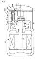
As shown inFigure 1 , a variable displacementwobble plate compressor 100 comprises amain shaft 3, arotor 10 fixed to themain shaft 3, a cam plate 1 connected to therotor 10 to be tiltable relative thereto and awobble plate 2 supported by the cam plate 1 throughbearings
A connectingrod 5 is provided with aspherical portion 4 at one end. Thewobble plate 2 is provided with a spherical concave. The connectingrod 5 is connected at one end to thewobble plate 2 by aball joint 23 formed by the spherical concave of thewobble plate 2 and thespherical portion 4 of the connectingrod 5 slidably fitting in the spherical concave of thewobble plate 2.
The connectingrod 5 is provided with aspherical portion 8 at the other end. Thespherical portion 8 is inserted in a piston 6 formed as a cylinder closed at one end. Acylindrical member 13 is fitted in the piston 6. Thecylindrical member 13 is fixed to the piston 6 as clamped between the caulkedopen end 14 of the piston 6 and thespherical portion 8 of the connectingrod 5. Thecylindrical member 13 forms a part of the piston 6. Thecylindrical member 13 is provided with a concave at one end. The concave forms a part of a spherical surface. The piston 6 is provided with a semispherical concave at the closed end. The concave provided on thecylindrical member 13 and the semispherical concave provided on the piston 6 cooperate to form a substantially spherical concave. The connectingrod 5 is connected at the other end to the piston 6 by aball joint 24 formed by the substantially spherical concave and thespherical portion 8 slidably fitted in the substantially spherical concave.
A small radial space 7 is formed between thecylindrical member 13 and the connectingrod 5. - The variable displacement
wobble plate compressor 100 further comprises acylinder bore 9 extending parallel to themain shaft 3. The piston 6 is inserted in thecylinder bore 9. One end of the cylinder bore 9 communicates with acrank chamber 15 for accommodating themain shaft 3, therotor 10, the cam plate 1, thewobble plate 2, thebearings suction hole 25 formed in a valve plate and adischarge chamber 12 through adischarge hole 26 formed in the valve plate. A suction valve for closing thesuction hole 25 and a discharge valve for closing thedischarge hole 26 are installed. The suction valve and the discharge valve are not shown inFigure 1 . Aretainer 27 for restricting excessive movement of the discharge valve is installed in thedischarge chamber 12.
One end of themain shaft 3 extends out of thecrank chamber 15 to be connected to a power source through a power transmission mechanism, neither of which is shown inFigure 1 . - In the variable displacement
wobble plate compressor 100, themain shaft 3 is driven by the power source to rotate, therotor 10 and the cam plate 1 are driven by themain shaft 3 to rotate, thewobble plate 2 is driven by the cam plate 1 to swing, and the piston 6 connected to thewobble plate 2 by the connectingrod 5 is driven by thewobble plate 2 to move reciprocally in thecylinder bore 9. Accompanying the reciprocal movement of the piston 6, fluid is sucked into the cylinder bore 9 from the suction chamber 11 through thesuction hole 25 and compressed in thecylinder bore 9. The compressed fluid is discharged from the cylinder bore 9 to thedischarge chamber 12 through thedischarge hole 26. - When the
wobble plate 2 swings and the piston 6 moves reciprocally, the center of the ball joint 23 for connecting the connectingrod 25 to thewobble plate 5, more specifically, the center of thespherical portion 4, reciprocally moves in the longitudinal direction of themain shaft 3 and orbits with small radius in the radial direction of themain shaft 3. The orbital motion of the center of thespherical portion 4 causes precession of theconnection rod 5 supported by the ball joint 24 connecting the connectingrod 5 to the piston 6 and motion of the connectingrod 5 relative to the piston 6. The small radial space 7 formed between thecylindrical member 13 and the connectingrod 5 prevents interference between thecylindrical member 13 and the connectingrod 5 to allow the precession of the connectingrod 5. The allowance of the precession of the connectingrod 5 leads to smooth movement of the piston 6.
When thewobble plate 2 is driven by the cam plate 1 to rotate, the rotation of thewobble plate 2 is transmitted to the connectingrod 5 through the ball joint 23 to cause swing of the connectingrod 5 beyond the range of the precession. As a result, the connectingrod 5 swings beyond the small radial space 7 to abut thecylindrical member 13 forming a part of the piston 6, thereby forcing the piston 6 to force the outer circumferential surface of the piston 6 against the inner circumferential surface of thecylinder bore 9. As a result, the swing of the connectingrod 5 is prevented and the rotation of thewobble plate 2 is prevented. - A mechanism for allowing the precession of the connecting
rod 5 and preventing the rotation of thewobble plate 2 by forcing the outer circumferential surface of the piston 6 against the inner circumferential surface of the cylinder bore 9 when the connectingrod 5 swings beyond the range of the precession can be structured simply and produced at low cost by thecylindrical member 13 fitted in and fixed to the piston 6 and the small radial space 7 disposed between thecylindrical member 13 and the connectingrod 5.
Prevention of rotation of thewobble plate 2 does not cause heavy noise or vibration because the outer circumferential surface of the piston 6 is forced against the inner circumferential surface of the cylinder bore 9 to prevent the rotation of thewobble plate 2. The variable displacementwobble plate compressor 100 is thus equipped with a mechanism for preventing rotation of the wobble plate which is simply structured, producible at low cost, and does not cause heavy noise or vibration. - The
cylindrical member 13 can be structured by a plurality of members or made of flexible material such as resin, etc. The piston 6 can be provided with a lubrication hole for supplying the ball joint 24 with lubrication oil. Thecylindrical member 13 can be pressed into, or welded to, or adhered to the piston 6. Thecylindrical member 13 can be formed integrally with the piston 6. The piston 6 can be coated with various kinds of lubricant. The piston 6 can be equipped with adequate number of piston rings. - The present invention can be applied to not only a variable displacement compressor, but also a fixed displacement compressor as shown in
Figure 2 or an electric compressor as shown inFigure 3 .
In a fixeddisplacement compressor 200 shown inFigure 2 , no cam plate is provided and awobble plate 2 is directly driven by a rotor 10a fixed to amain shaft 3a to swing. Similarly to the variable displacementwobble plate compressor 100, one end of a connectingrod 5a is connected to thewobble plate 2 by a ball joint 23 provided with aspherical portion 4. However, the other end of the connectingrod 5a is fixed to a piston 6a. A small radial space 7a is formed between the outer circumferential surface of the piston 6a and the inner circumferential surface of acylinder bore 9.
The connectingrod 5a and the piston 6a do not move relatively but unitarily because the connectingrod 5a is fixed to the piston 6a at the other end. Therefore, the connectingrod 5a and the piston 6a can precess if only the radial space 7a is formed between the outer circumferential surface of the piston 6a and the inner circumferential surface of the cylinder bore 9 to allow the precession of the connectingrod 5a during the reciprocal movement of the piston 6a. When the connectingrod 5a and the piston 6a is driven by therotating wobble plate 2 to swing beyond the range of the precession, the piston 6a swings beyond the radial space 7a, and the outer circumferential surface of the piston 6a is forced against the inner circumferential surface of thecylinder bore 9. As a result, the swing of the connectingrod 5a is prevented and the rotation of thewobble plate 2 is prevented.
In anelectric compressor 300 shown inFigure 3 , a main shaft 3b is driven by a built-inelectric motor 31. No cam plate is equipped. Displacement of the compressor is fixed. The structures of a piston 6, a connectingrod 5 andball joints wobble plate compressor 100. - Other preferred embodiments are shown in
Figures 4 to 6 .
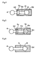
In a preferred embodiment shown inFigure 4 , apiston 6b is provided with a concave formed by acaulking 41. The concave forms a part of a spherical surface. Thepiston 6b has a cylindrical shape closed at one end and is provided with a semispherical concave at the closed end. The concave formed by thecaulking 41 and the semispherical concave provided on the closed end cooperate to form a substantially spherical concave. The other end of the connectingrod 5b is connected to thepiston 6b by a ball joint formed by the substantially spherical concave and aspherical portion 8 slidably fitted therein.
The connectingrod 5b is provided with alarge diameter portion 42. A smallradial space 7b is formed between the circumferential sidewall of thepiston 6b and thelarge diameter portion 42 of the connectingrod 5b. Thespace 7b allows precession of the connectingrod 5b during the reciprocal movement of thepiston 6b.
When thewobble plate 2 rotates, the rotation of thewobble plate 2 is transmitted to the connectingrod 5b through a ball joint for connecting the connectingrod 5b to thewobble plate 2 and the connectingrod 5b swings beyond the range of the precession. As a result, thelarge diameter portion 42 of the connectingrod 5b swings beyond the smallradial space 7b to abut the circumferential sidewall of thepiston 6b, thereby forcing thepiston 6b and forcing the outer circumferential surface of thepiston 6b against the inner circumferential surface of thecylinder bore 9. As a result, the swing of the connectingrod 5b is prevented and the rotation of thewobble plate 2 is prevented. - In a preferred embodiment shown in
Figure 5 , asemispherical portion 8c is provided on the other end of a connectingrod 5c. Apiston 6c has a cylindrical shape closed at one end and is provided with a semispherical concave at the closed end. Thesemispherical portion 8c slidably fits in the semispherical concave. Apin 51 passes through thepiston 6c and thesemispherical portion 8c to be fixed to thepiston 6c, thereby connecting the other end of the connectingrod 5c to thepiston 6c. A small amount of play is provided between thepin 51 and the part of thesemispherical portion 8c through which thepin 51 passes.
The connectingrod 5c is provided with alarge diameter portion 52. A smallradial space 7c is formed between the circumferential sidewall of thepiston 6c and thelarge diameter portion 52 of the connectingrod 5c. Thespace 7c allows precession of the connectingrod 5c during the reciprocal movement of thepiston 6c.
When thewobble plate 2 rotates, the rotation of thewobble plate 2 is transmitted to the connectingrod 5c through a ball joint for connecting the connectingrod 5c to thewobble plate 2 and the connectingrod 5c swings beyond the range of the precession. As a result, thelarge diameter portion 52 of the connectingrod 5c swings beyond the smallradial space 7c to abut the circumferential side wall of thepiston 6c, thereby forcing thepiston 6c and forcing the outer circumferential surface of thepiston 6c against the inner circumferential surface of thecylinder bore 9. As a result, the swing of the connectingrod 5c is prevented and the rotation of thewobble plate 2 is prevented. - In a preferred embodiment shown in
Figure 6 , the other end of thepiston 5 is fixed to apiston 6d and thepiston 6d is made of flexible material such as resin, etc.
When the connectingrod 5 is fixed to thepiston 6d and moves unitarily with thepiston 6d, the connectingrod 5 can precess smoothly and thepiston 6d can reciprocally move smoothly if only thepiston 6d is made of flexible material to bend accompanying the precession of the connectingrod 5. - The present invention can be widely used in both variable displacement compressors and fixed displacement compressors.
-
-
Figure 1 is a longitudinal sectional view of a variable displacement wobble plate compressor in accordance with a preferred embodiment of the present invention. -
Figure 2 is a longitudinal sectional view of a fixed displacement wobble plate compressor in accordance with another preferred embodiment of the present invention. -
Figure 3 is a longitudinal sectional view of an electric fixed displacement wobble plate compressor in accordance with another preferred embodiment of the present invention. -
Figure 4 is a longitudinal sectional view of a connecting rod and a piston of a wobble plate compressor in accordance with another preferred embodiment of the present invention. -
Figure 5 is a longitudinal sectional view of a connecting rod and a piston of a wobble plate compressor in accordance with another preferred embodiment of the present invention. -
Figure 6 is a longitudinal sectional view of a connecting rod and a piston of a wobble plate compressor in accordance with another preferred embodiment of the present invention.
Claims (7)
- A wobble plate compressor comprising a main shaft driven by a power source, a wobble plate driven by the main shaft to swing, a piston connected to the wobble plate by a connecting rod, and a cylinder bore extending parallel to the main shaft to accept the piston, wherein the connecting rod is connected to the wobble plate by a ball joint, precession of the connecting rod is allowed when the piston moves reciprocally, and the outer circumferential surface of the piston is forced against the inner circumferential surface of the cylinder bore when the wobble plate is driven by the main shaft to rotate and the connecting rod is driven by the rotating wobble plate to swing beyond the range of the precession, thereby preventing rotation of the wobble plate.
- A wobble plate compressor of claim 1, wherein the connecting rod is connected to the piston by a ball joint, a radial space is formed between the piston and the connecting rod to allow the precession of the connecting rod when the piston moves reciprocally, and the connecting rod abuts the piston to force it when the connecting rod is driven by the rotating wobble plate to swing beyond the range of the precession, thereby forcing the outer circumferential surface of the piston against the inner circumferential surface of the cylinder bore.
- A wobble plate compressor of claim 1, wherein the connecting rod is connected to the piston by a pin, a radial space is formed between the piston and the connecting rod to allow the precession of the connecting rod when the piston moves reciprocally, and the connecting rod abuts the piston to force it when the connecting rod is driven by the rotating wobble plate to swing beyond the range of the precession, thereby forcing the outer circumferential surface of the piston against the inner circumferential surface of the cylinder bore.
- A wobble plate compressor of claim 2 or 3, wherein a cylindrical member is fitted in and fixed to the piston to form a part of the piston, and the radial space for allowing the precession of the connecting rod when the piston moves reciprocally is formed between the cylindrical member and the connecting rod.
- A wobble plate compressor of claim 2 or 3, wherein the connecting rod is provided with a portion with large diameter, and the radial space for allowing the precession of the connecting rod when the piston moves reciprocally is formed between the piston and the portion of the connecting rod with large diameter.
- A wobble plate compressor of claim 1, wherein the connecting rod is fixed to the piston, a radial space is formed between the outer circumferential surface of the piston and the inner circumferential surface of the cylinder bore to allow the precession of the connecting rod when the piston moves reciprocally, and the outer circumferential surface of the piston is forced against the inner circumferential surface of the cylinder bore when the connecting rod is driven by the rotating wobble plate to swing beyond the range of the precession.
- A wobble plate compressor of claim 6, wherein the piston is made of flexible material.
Applications Claiming Priority (2)
| Application Number | Priority Date | Filing Date | Title |
|---|---|---|---|
| JP2005279453A JP4705445B2 (en) | 2005-09-27 | 2005-09-27 | Swing plate compressor |
| PCT/JP2006/314547 WO2007037061A1 (en) | 2005-09-27 | 2006-07-24 | Oscillation plate type compressor |
Publications (2)
| Publication Number | Publication Date |
|---|---|
| EP1930590A1 true EP1930590A1 (en) | 2008-06-11 |
| EP1930590A4 EP1930590A4 (en) | 2008-09-17 |
Family
ID=37899497
Family Applications (1)
| Application Number | Title | Priority Date | Filing Date |
|---|---|---|---|
| EP06781469A Withdrawn EP1930590A4 (en) | 2005-09-27 | 2006-07-24 | Oscillation plate type compressor |
Country Status (5)
| Country | Link |
|---|---|
| US (1) | US8028614B2 (en) |
| EP (1) | EP1930590A4 (en) |
| JP (1) | JP4705445B2 (en) |
| CN (1) | CN101273198A (en) |
| WO (1) | WO2007037061A1 (en) |
Families Citing this family (12)
| Publication number | Priority date | Publication date | Assignee | Title |
|---|---|---|---|---|
| JP4592557B2 (en) * | 2005-10-12 | 2010-12-01 | サンデン株式会社 | Swing plate compressor |
| MX2011003624A (en) | 2008-10-22 | 2012-01-27 | Graco Minnesota Inc | Portable airless sprayer. |
| US9545643B2 (en) | 2008-10-22 | 2017-01-17 | Graco Minnesota Inc. | Portable airless sprayer |
| EP2427273B1 (en) * | 2009-05-07 | 2017-07-12 | Graco Minnesota Inc. | Wobble assembly for fluid pumping mechanism |
| DE102009056903A1 (en) * | 2009-12-03 | 2011-06-09 | Danfoss A/S | Hydraulic piston machine, in particular water-hydraulic machine |
| US11007545B2 (en) | 2017-01-15 | 2021-05-18 | Graco Minnesota Inc. | Handheld airless paint sprayer repair |
| CN111032564A (en) * | 2017-09-13 | 2020-04-17 | 株式会社岛津制作所 | Control valve |
| CN112368082B (en) | 2018-04-10 | 2022-11-08 | 固瑞克明尼苏达有限公司 | Handheld airless sprayer for paints and other coatings |
| CN115739435A (en) | 2019-05-31 | 2023-03-07 | 固瑞克明尼苏达有限公司 | Hand-held fluid sprayer |
| US10968903B1 (en) | 2020-06-04 | 2021-04-06 | Graco Minnesota Inc. | Handheld sanitary fluid sprayer having resilient polymer pump cylinder |
| US10926275B1 (en) | 2020-06-25 | 2021-02-23 | Graco Minnesota Inc. | Electrostatic handheld sprayer |
| CN115005090B (en) * | 2022-04-21 | 2023-12-12 | 重庆市酉阳县桑竹农业开发有限责任公司 | Wisdom is slice planting thing pollination device for agricultural |
Family Cites Families (12)
| Publication number | Priority date | Publication date | Assignee | Title |
|---|---|---|---|---|
| DE1110479B (en) | 1960-07-21 | 1961-07-06 | Brueninghaus Gmbh Stahlwerke | Piston for an axial piston machine |
| DE1232025B (en) * | 1960-11-02 | 1967-01-05 | Linde Ag | Arrangement for transmitting torque transverse forces on an axial piston machine |
| DE3333812C2 (en) * | 1983-09-19 | 1986-08-07 | Hydromatik GmbH, 7915 Elchingen | Swivel drum axial piston machine |
| KR910004933A (en) * | 1989-08-09 | 1991-03-29 | 미다 가쓰시게 | Variable displacement swash plate compressor |
| JP3026518B2 (en) * | 1991-07-03 | 2000-03-27 | サンデン株式会社 | Variable capacity rocking plate compressor |
| JPH0599146A (en) * | 1991-10-07 | 1993-04-20 | Toyota Autom Loom Works Ltd | Piston for fluid machine and manufacture thereof |
| JP2000054954A (en) | 1998-08-07 | 2000-02-22 | Toyota Autom Loom Works Ltd | Manufacture of piston for variable displacement compressor |
| JP2000345958A (en) | 1999-06-02 | 2000-12-12 | Sanden Corp | Rotation checking mechanism and compressor having the mechanism |
| JP2001041155A (en) | 1999-07-28 | 2001-02-13 | Zexel Valeo Climate Control Corp | Variable-displacement swash plate compressor |
| DE19954863A1 (en) | 1999-11-15 | 2001-07-26 | Zexel Valeo Compressor Europe | Piston machine, especially compressor |
| DE10250591B4 (en) * | 2001-11-02 | 2018-01-18 | Denso Corporation | Compressor with guide grooves as connecting mechanism between drive pulley and shaft |
| JP2004132327A (en) * | 2002-10-15 | 2004-04-30 | Sanden Corp | Compressor |
-
2005
- 2005-09-27 JP JP2005279453A patent/JP4705445B2/en not_active Expired - Fee Related
-
2006
- 2006-07-24 CN CNA2006800354955A patent/CN101273198A/en active Pending
- 2006-07-24 EP EP06781469A patent/EP1930590A4/en not_active Withdrawn
- 2006-07-24 US US12/067,886 patent/US8028614B2/en not_active Expired - Fee Related
- 2006-07-24 WO PCT/JP2006/314547 patent/WO2007037061A1/en not_active Ceased
Also Published As
| Publication number | Publication date |
|---|---|
| EP1930590A4 (en) | 2008-09-17 |
| US20090139396A1 (en) | 2009-06-04 |
| JP2007092536A (en) | 2007-04-12 |
| JP4705445B2 (en) | 2011-06-22 |
| WO2007037061A1 (en) | 2007-04-05 |
| CN101273198A (en) | 2008-09-24 |
| US8028614B2 (en) | 2011-10-04 |
Similar Documents
| Publication | Publication Date | Title |
|---|---|---|
| CN116194669B (en) | Piston-cylinder assembly for radial piston compressor and radial piston compressor | |
| US5951261A (en) | Reversible drive compressor | |
| US8028614B2 (en) | Wobble plate compressor | |
| WO2018025765A1 (en) | Actuator of link mechanism for internal-combustion engine | |
| US6719537B2 (en) | Compressor and pulley for compressor | |
| JP2014202162A (en) | Scroll type fluid machine | |
| JP2010043608A (en) | Scroll fluid machine | |
| JP2012149632A (en) | Variable displacement type internal gear pump | |
| JP2002340097A (en) | Rotor and compressor | |
| JP2016017429A (en) | Hydraulic rotating machine | |
| KR20070016809A (en) | Structure to prevent rotating of scroll compressor | |
| KR20060085002A (en) | Piston anti-rotation structure, and variable displacement swash plate compressor including the same | |
| JP5500566B2 (en) | Scroll type fluid machinery | |
| EP1898090A2 (en) | Variable displacement compressor | |
| EP1918582A2 (en) | Bearing structure in rotating machine | |
| KR200293348Y1 (en) | Hermetic reciprocating compressor | |
| KR100621379B1 (en) | Connecting rod of hermetic compressor | |
| KR20130109499A (en) | Shaft support structure of a swash plate type compressor | |
| JPH0643507Y2 (en) | Variable capacity swash plate compressor | |
| KR200416400Y1 (en) | Joint of sleeve and connecting rod of hermetic compressor | |
| KR20040106728A (en) | Shaft for hermetic rotary compressor | |
| JP2010031794A (en) | Scroll type fluid machine | |
| JP2007198281A (en) | Swash plate type compressor | |
| JP2003120515A (en) | Variable displacement swash plate type hydraulic rotating machine | |
| JP2007205233A (en) | Swash plate compressor |
Legal Events
| Date | Code | Title | Description |
|---|---|---|---|
| PUAI | Public reference made under article 153(3) epc to a published international application that has entered the european phase |
Free format text: ORIGINAL CODE: 0009012 |
|
| 17P | Request for examination filed |
Effective date: 20080313 |
|
| AK | Designated contracting states |
Kind code of ref document: A1 Designated state(s): DE FR |
|
| A4 | Supplementary search report drawn up and despatched |
Effective date: 20080820 |
|
| RBV | Designated contracting states (corrected) |
Designated state(s): DE FR |
|
| 17Q | First examination report despatched |
Effective date: 20090312 |
|
| STAA | Information on the status of an ep patent application or granted ep patent |
Free format text: STATUS: THE APPLICATION IS DEEMED TO BE WITHDRAWN |
|
| 18D | Application deemed to be withdrawn |
Effective date: 20090722 |