EP1930555A2 - Mid-turbine frame - Google Patents
Mid-turbine frame Download PDFInfo
- Publication number
- EP1930555A2 EP1930555A2 EP07254594A EP07254594A EP1930555A2 EP 1930555 A2 EP1930555 A2 EP 1930555A2 EP 07254594 A EP07254594 A EP 07254594A EP 07254594 A EP07254594 A EP 07254594A EP 1930555 A2 EP1930555 A2 EP 1930555A2
- Authority
- EP
- European Patent Office
- Prior art keywords
- load
- mid
- turbine frame
- torque box
- struts
- Prior art date
- Legal status (The legal status is an assumption and is not a legal conclusion. Google has not performed a legal analysis and makes no representation as to the accuracy of the status listed.)
- Granted
Links
Images

Classifications
-
- F—MECHANICAL ENGINEERING; LIGHTING; HEATING; WEAPONS; BLASTING
- F01—MACHINES OR ENGINES IN GENERAL; ENGINE PLANTS IN GENERAL; STEAM ENGINES
- F01D—NON-POSITIVE DISPLACEMENT MACHINES OR ENGINES, e.g. STEAM TURBINES
- F01D25/00—Component parts, details, or accessories, not provided for in, or of interest apart from, other groups
- F01D25/16—Arrangement of bearings; Supporting or mounting bearings in casings
- F01D25/162—Bearing supports
Definitions
- the present invention generally relates to the field of gas turbine engines.
- the invention relates to a mid-turbine frame for a jet turbine engine.
- Turbofans are a type of gas turbine engine commonly used in aircraft, such as jets.
- the turbofan generally includes a high and a low pressure compressor, a high and a low pressure turbine, a high pressure rotatable shaft, a low pressure rotatable shaft, a fan, and a combuster.
- the high-pressure compressor (HPC) is connected to the high pressure turbine (HPT) by the high pressure rotatable shaft, together acting as a high pressure system.
- the low pressure compressor (LPC) is connected to the low pressure turbine (LPT) by the low pressure rotatable shaft, together acting as a low pressure system.
- the low pressure rotatable shaft is housed within the high pressure shaft and is connected to the fan such that the HPC, HPT, LPC, LPT, and high and low pressure shafts are coaxially aligned.
- bearings are located within the jet turbine engine to help distribute the load created by the high and low pressure systems.
- the bearings are connected to an engine casing that houses a mid-turbine frame located between the HPT and the LPT by bearing support structures.
- the bearing support structures can be, for example, bearing cones.
- the loads from the bearing support structures are transferred to the engine casing through the mid-turbine frame. Decreasing the weight of the engine casing can significantly increase the efficiency of the jet turbine engine and the jet itself.
- a mid-turbine frame is connected to at least one mount of a gas turbine engine for transferring a first load from a first bearing and a second load from a second bearing to the mount.
- the mid-turbine frame includes a first load structure, a second load structure, and a plurality of struts.
- the first load structure combines the first load and the second load into a combined load.
- the second load structure transfers the combined load to the mount.
- the struts are connected between the first load structure and the second load structure and transfers the combined load from the first load structure to the second load structure.
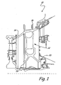
- FIG. 1 shows a partial sectional view of an intermediate portion of a gas turbine engine 10 about a gas turbine engine axis centerline.
- Gas turbine engine 10 generally includes mid-turbine frame 12, engine casing 14, mounts 16, first bearing 18, and second bearing 20.
- Mid-turbine frame 12 of gas turbine engine 10 has a lightweight design that efficiently transfers loads from first and second bearings 18 and 20 through mid-turbine frame 12 to engine casing 14.
- Mid-turbine frame 12 adds stiffness to engine casing 14 and creates a higher load carrying capacity.
- Mid-turbine frame 12 is housed within engine casing 14 of gas turbine engine 10 and is connected to engine casing 14 and first and second bearings 18 and 20.
- Engine casing 14 protects mid-turbine frame 12 from its surroundings and transfers the loads from mid-turbine frame 12 to mounts 16. Due to the design of mid-turbine frame 12, mid-turbine frame 12 has reduced weight compared to current mid-turbine frames available in the art. Mid-turbine frame 12 is applicable in both low thrust engines and high thrust engines having any thrust ratings or operating envelopes.
- First and second bearings 18 and 20 are located at forward and aft ends of gas turbine engine 10, respectively, below mid-turbine frame 12. First and second bearings 18 and 20 support thrust loads, vertical tension, side gyroscopic loads, as well as vibratory loads from high and low pressure rotors located in gas turbine engine 10. All of the loads supported by first and second bearings 18 and 20 are transferred to engine casing 14 and mounts 16 through mid-turbine frame 12. Second bearing 20 is typically designed to support a greater load than first bearing 18, so mid-turbine frame 12 is designed for stiffness and structural feasibility assuming that second bearing 20 is the extreme situation.
- FIG. 2 shows an enlarged perspective view of mid-turbine frame 12 within engine casing 14.
- Mid-turbine frame 12 generally includes first torque box 22, struts 24, and second torque box 26.
- First and second bearings 18 and 20 (shown in FIG. 1 ) are connected to mid-turbine frame 12 by first bearing cone 28 and second bearing cone 30 (shown in FIGS. 3 , 4A, and 4B ), respectively.
- First and second bearing cones 28 and 30 transfer the loads from first and second bearings 18 and 20 to mid-turbine frame 12 and are stationary relative to continuously rotating high and low pressure rotors.
- First torque box 22 has a shell structure and is positioned between first and second bearing cones 28 and 30 and struts 24. First torque box 22 takes the loads, or torque, from first and second bearing cones 28 and 30 and combines them prior to transferring the loads to struts 24, which extend from along the circumference of torque box 22.
- Struts 24 of mid-turbine frame 12 extend from first torque box 22 and transfer the loads from first and second bearing cones 28 and 30 entering through first torque box 22 to engine casing 14.
- Each of struts 24 has a first end 32 connected to first torque box 22 and a second end 34 connected to engine casing 14. The loads travel from torque box 22 through struts 24 to engine casing 14.
- nine struts are positioned approximately forty degrees apart from one another along the circumference of first torque box 22.
- twelve total struts are positioned approximately thirty degrees apart from one another along the circumference of first torque box 22.
- Second torque box 26 is U-shaped and is positioned between struts 24 and engine casing 14. Second torque box 26 takes the loads, or torque, from struts 24 and transfers the loads to engine casing 14.
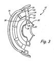
- FIG. 3 shows a cut-away view of mid-turbine frame 12.
- struts 24 connect mid-turbine frame 12 to engine casing 14.
- First end 32 of struts 24 is connected to first torque box 22 and second end 34 of struts 24 is connected to second torque box 26.
- This allows for the overall length of struts 24 to be decreased, eliminating the need for massive structural components between first and second torque boxes 22 and 24 to transfer the loads from first and second bearings 18 and 20.
- the shortened length of struts 24 increases the critical buckling load as well as the load carrying capacity of struts 24.
- struts 24 may also be hollow, further reducing the weight of mid-turbine frame 12.
- first and second bearings 18 and 20 are transferred through first and second bearing cones 28 and 30, respectively, and combine at first torque box 22.
- Struts 24 then carry the loads to second torque box 26, which transfers the combined load through to engine casing 14.
- the U-shape design of both first torque box 22 and second torque box 26 provides dual U-load transfer areas, allowing efficient load transfer through mid-turbine frame 12 and engine casing 14 to mounts 16.
- the U-structure is beneficial because of the membrane bending efficiency of shell structures, reducing the overall weight of mid-turbine frame 12.
- FIG. 3 depicts second torque box 26 as extending all the way around the inner circumference of engine casing 14, the second torque box 26 may optionally not complete a 360 degree rotation around engine casing 14.
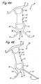
- FIG. 4A shows a cross-sectional view of mid-turbine frame 12.
- First torque box 22 is a U-shape shell structure and generally includes U-stem 36 and U-branch 38.
- the U-shape shell structure allows first torque box 22 to exhibit both membrane behavior and bending behavior.
- the membrane behavior of the U-shape shell structure allows first torque box 22 the ability to stretch in the plane.
- the bending behavior of the U-shape shell structure allows first torque box 22 the ability to deform in a plane orthogonal to the stretching plane. Due to this membrane bending behavior of U-shape shell structure, first torque box 22 can carry more load compared to a plate structure that is in the plane and only exhibits membrane behavior.
- U-stem 36 of mid-turbine frame 12 is positioned below first torque box 22 and is formed from first bearing cone 28, second bearing cone 30, and region 40 where first and second bearing cones 28 and 30 merge.
- the loads of first and second bearing cones 28 and 30 converge to a single point at region 40 where the loads are introduced into torque box 22 by U-stem 36, which carries the effective load.
- U-branch 38 is connected between first torque box 22 and U-stem 36. By connecting U-branch 38 to region 40 of U-stem 36, U-branch 38 can function as a bearing arm load transfer member.
- U-branch 38 acts as a load transfer member because the loads entering U-branch 38 are smaller than the total load entering first torque box 22. U-branch 38 then subsequently transfers the loads to struts 24. This ensures that the loads from first and second bearings 18 and 20 are transferred through the individual U-branches 38, which provide the effective minimum area needed for load transfer. Because the vertical loads from first and second bearings 18 and 20 are divided, first torque box 22 only needs a small cross-sectional wall area at U-branch 38, allowing thin U-branches 38 and reducing the overall weight of torque box 22. Mid-turbine frame 12 can thus handle large loads without deflecting.
- Second torque box 26 is also formed of a U-shape shell structure and functions in substantially the same manner as first torque box 22. Second torque box 26 is connected to engine casing 14 at the top of second torque box 26 and takes the combined load from struts 24 to engine casing 14. The majority of the load from mounts 16 is also taken by second torque box 26.
- the U-shape of second torque box 26 acts as a local stiffener in the circumferential direction for engine casing 14 and leads to increased local membrane-bending stiffness, enabling local stress redistribution and transfer from struts 24 to engine casing 14.
- FIG. 4B shows a cross-sectional view of a second embodiment of mid-turbine frame 12a.
- FIGS. 1 , 3 , and 4A depict struts 24 positioned orthogonal with respect to first torque box 22 and second torque box 26, struts 24 may also be tilted with respect to both first torque box 22 and second torque box 26, as shown in FIG. 4B .
- the loads from first and second bearings 18 and 20 meet at region 40, but do not meet at the center of region 40. After converging at U-stem 36, the loads propagate into struts 24 along U-stem 36 and U-branch 38, similarly to the first embodiment of mid-turbine frame 12.
- the mid-turbine frame design with double U-shaped transfer load structures offers a lightweight structure that efficiently distributes load from a first bearing and a second bearing to a pair of engine mounts.
- the loads from the first and second bearings first pass through a mid-turbine frame having a plurality of struts that attach the mid-turbine frame to the engine casing.
- the mid-turbine frame also includes a first U-shaped torque box that combines the loads from the first and second bearings to a first end of the struts.
- the second end of the struts of the mid-turbine frame is connected to a second torque box which also has a U-shape.
- the second torque box connects the struts to the engine casing.
- the dual U-shaped load transfer structures of the mid-turbine frame provide localized stiffening of the mid-turbine frame as well as multi-directional load transfer.
- the U-shape of the second torque box shortens the length of the struts, reducing the overall weight of the mid-turbine frame.
- the mid-turbine frame may be used in engines of any size and thrust capacity. Depending on the size of the engine, any appropriate number of struts may be used.
- all of the components parts of the mid-turbine frame, such as the bearing cones, torque boxes, and struts, may be manufactured separately or may be formed or cast integrally with one another.
Abstract
Description
- The present invention generally relates to the field of gas turbine engines. In particular, the invention relates to a mid-turbine frame for a jet turbine engine.
- Turbofans are a type of gas turbine engine commonly used in aircraft, such as jets. The turbofan generally includes a high and a low pressure compressor, a high and a low pressure turbine, a high pressure rotatable shaft, a low pressure rotatable shaft, a fan, and a combuster. The high-pressure compressor (HPC) is connected to the high pressure turbine (HPT) by the high pressure rotatable shaft, together acting as a high pressure system. Likewise, the low pressure compressor (LPC) is connected to the low pressure turbine (LPT) by the low pressure rotatable shaft, together acting as a low pressure system. The low pressure rotatable shaft is housed within the high pressure shaft and is connected to the fan such that the HPC, HPT, LPC, LPT, and high and low pressure shafts are coaxially aligned.
- Outside air is drawn into the jet turbine engine by the fan and the HPC, which increases the pressure of the air drawn into the system. The high-pressure air then enters the combuster, which burns fuel and emits the exhaust gases. The HPT directly drives the HPC using the fuel by rotating the high pressure shaft. The LPT uses the exhaust generated in the combuster to turn the low pressure shaft, which powers the fan to continually bring air into the system. The air brought in by the fan bypasses the HPT and LPT and acts to increase the engine's thrust, driving the jet forward.
- In order to support the high and low pressure systems, bearings are located within the jet turbine engine to help distribute the load created by the high and low pressure systems. The bearings are connected to an engine casing that houses a mid-turbine frame located between the HPT and the LPT by bearing support structures. The bearing support structures can be, for example, bearing cones. The loads from the bearing support structures are transferred to the engine casing through the mid-turbine frame. Decreasing the weight of the engine casing can significantly increase the efficiency of the jet turbine engine and the jet itself.
- According to one aspect of the invention, a mid-turbine frame is connected to at least one mount of a gas turbine engine for transferring a first load from a first bearing and a second load from a second bearing to the mount. The mid-turbine frame includes a first load structure, a second load structure, and a plurality of struts. The first load structure combines the first load and the second load into a combined load. The second load structure transfers the combined load to the mount. The struts are connected between the first load structure and the second load structure and transfers the combined load from the first load structure to the second load structure.
-
-
FIG. 1 is a partial sectional view of an intermediate portion of a gas turbine engine. -
FIG. 2 is an enlarged perspective view of a mid-turbine frame. -
FIG. 3 is a cut-away view of the mid-turbine frame. -
FIG. 4A is a cross-sectional view of a first embodiment of a segment of the mid-turbine frame. -
FIG. 4B is a cross-sectional view of a second embodiment of the segment of the mid-turbine frame. -
FIG. 1 shows a partial sectional view of an intermediate portion of agas turbine engine 10 about a gas turbine engine axis centerline.Gas turbine engine 10 generally includesmid-turbine frame 12,engine casing 14,mounts 16, first bearing 18, and second bearing 20.Mid-turbine frame 12 ofgas turbine engine 10 has a lightweight design that efficiently transfers loads from first andsecond bearings mid-turbine frame 12 toengine casing 14.Mid-turbine frame 12 adds stiffness toengine casing 14 and creates a higher load carrying capacity. - Mid-turbine
frame 12 is housed withinengine casing 14 ofgas turbine engine 10 and is connected toengine casing 14 and first andsecond bearings Engine casing 14 protectsmid-turbine frame 12 from its surroundings and transfers the loads frommid-turbine frame 12 tomounts 16. Due to the design ofmid-turbine frame 12,mid-turbine frame 12 has reduced weight compared to current mid-turbine frames available in the art.Mid-turbine frame 12 is applicable in both low thrust engines and high thrust engines having any thrust ratings or operating envelopes. - First and
second bearings gas turbine engine 10, respectively, belowmid-turbine frame 12. First andsecond bearings gas turbine engine 10. All of the loads supported by first andsecond bearings engine casing 14 and mounts 16 throughmid-turbine frame 12. Second bearing 20 is typically designed to support a greater load than first bearing 18, somid-turbine frame 12 is designed for stiffness and structural feasibility assuming that second bearing 20 is the extreme situation. -
FIG. 2 shows an enlarged perspective view ofmid-turbine frame 12 withinengine casing 14.Mid-turbine frame 12 generally includesfirst torque box 22,struts 24, andsecond torque box 26. First andsecond bearings 18 and 20 (shown inFIG. 1 ) are connected tomid-turbine frame 12 by first bearingcone 28 and second bearing cone 30 (shown inFIGS. 3 ,4A, and 4B ), respectively. First andsecond bearing cones second bearings mid-turbine frame 12 and are stationary relative to continuously rotating high and low pressure rotors. -
First torque box 22 has a shell structure and is positioned between first andsecond bearing cones struts 24.First torque box 22 takes the loads, or torque, from first andsecond bearing cones struts 24, which extend from along the circumference oftorque box 22. -
Struts 24 ofmid-turbine frame 12 extend fromfirst torque box 22 and transfer the loads from first andsecond bearing cones first torque box 22 toengine casing 14. Each ofstruts 24 has afirst end 32 connected tofirst torque box 22 and asecond end 34 connected toengine casing 14. The loads travel fromtorque box 22 throughstruts 24 toengine casing 14. In one embodiment, nine struts are positioned approximately forty degrees apart from one another along the circumference offirst torque box 22. In another embodiment, twelve total struts are positioned approximately thirty degrees apart from one another along the circumference offirst torque box 22. -
Second torque box 26 is U-shaped and is positioned betweenstruts 24 andengine casing 14.Second torque box 26 takes the loads, or torque, fromstruts 24 and transfers the loads toengine casing 14. -
FIG. 3 shows a cut-away view ofmid-turbine frame 12. As can be seen inFIG. 3 ,struts 24 connectmid-turbine frame 12 toengine casing 14.First end 32 ofstruts 24 is connected tofirst torque box 22 andsecond end 34 ofstruts 24 is connected tosecond torque box 26. Due to the U-shape structures of first andsecond torque boxes struts 24 connect with first andsecond torque boxes struts 24 to be decreased, eliminating the need for massive structural components between first andsecond torque boxes second bearings struts 24 increases the critical buckling load as well as the load carrying capacity ofstruts 24. In addition to the shortened length,struts 24 may also be hollow, further reducing the weight ofmid-turbine frame 12. - In operation, the loads from first and
second bearings second bearing cones first torque box 22.Struts 24 then carry the loads tosecond torque box 26, which transfers the combined load through toengine casing 14. The U-shape design of bothfirst torque box 22 andsecond torque box 26 provides dual U-load transfer areas, allowing efficient load transfer throughmid-turbine frame 12 andengine casing 14 to mounts 16. The U-structure is beneficial because of the membrane bending efficiency of shell structures, reducing the overall weight ofmid-turbine frame 12. - Although
FIG. 3 depictssecond torque box 26 as extending all the way around the inner circumference ofengine casing 14, thesecond torque box 26 may optionally not complete a 360 degree rotation aroundengine casing 14. -
FIG. 4A shows a cross-sectional view ofmid-turbine frame 12.First torque box 22 is a U-shape shell structure and generally includes U-stem 36 and U-branch 38. The U-shape shell structure allowsfirst torque box 22 to exhibit both membrane behavior and bending behavior. The membrane behavior of the U-shape shell structure allowsfirst torque box 22 the ability to stretch in the plane. The bending behavior of the U-shape shell structure allowsfirst torque box 22 the ability to deform in a plane orthogonal to the stretching plane. Due to this membrane bending behavior of U-shape shell structure,first torque box 22 can carry more load compared to a plate structure that is in the plane and only exhibits membrane behavior. -
U-stem 36 ofmid-turbine frame 12 is positioned belowfirst torque box 22 and is formed fromfirst bearing cone 28,second bearing cone 30, andregion 40 where first andsecond bearing cones second bearing cones region 40 where the loads are introduced intotorque box 22 by U-stem 36, which carries the effective load. As the loads decompose into components, they are equilibrated along U-branch 38 and are cancelled. U-branch 38 is connected betweenfirst torque box 22 andU-stem 36. By connecting U-branch 38 toregion 40 of U-stem 36, U-branch 38 can function as a bearing arm load transfer member. U-branch 38 acts as a load transfer member because the loads entering U-branch 38 are smaller than the total load enteringfirst torque box 22. U-branch 38 then subsequently transfers the loads to struts 24. This ensures that the loads from first andsecond bearings second bearings first torque box 22 only needs a small cross-sectional wall area at U-branch 38, allowing thin U-branches 38 and reducing the overall weight oftorque box 22.Mid-turbine frame 12 can thus handle large loads without deflecting. -
Second torque box 26 is also formed of a U-shape shell structure and functions in substantially the same manner asfirst torque box 22.Second torque box 26 is connected toengine casing 14 at the top ofsecond torque box 26 and takes the combined load fromstruts 24 toengine casing 14. The majority of the load frommounts 16 is also taken bysecond torque box 26. The U-shape ofsecond torque box 26 acts as a local stiffener in the circumferential direction forengine casing 14 and leads to increased local membrane-bending stiffness, enabling local stress redistribution and transfer fromstruts 24 toengine casing 14. -
FIG. 4B shows a cross-sectional view of a second embodiment ofmid-turbine frame 12a. AlthoughFIGS. 1 ,3 , and4A depict struts 24 positioned orthogonal with respect tofirst torque box 22 andsecond torque box 26, struts 24 may also be tilted with respect to bothfirst torque box 22 andsecond torque box 26, as shown inFIG. 4B . In the second embodiment ofmid-turbine frame 12a, the loads from first andsecond bearings region 40, but do not meet at the center ofregion 40. After converging at U-stem 36, the loads propagate intostruts 24 alongU-stem 36 and U-branch 38, similarly to the first embodiment ofmid-turbine frame 12. - The mid-turbine frame design with double U-shaped transfer load structures offers a lightweight structure that efficiently distributes load from a first bearing and a second bearing to a pair of engine mounts. The loads from the first and second bearings first pass through a mid-turbine frame having a plurality of struts that attach the mid-turbine frame to the engine casing. The mid-turbine frame also includes a first U-shaped torque box that combines the loads from the first and second bearings to a first end of the struts. The second end of the struts of the mid-turbine frame is connected to a second torque box which also has a U-shape. The second torque box connects the struts to the engine casing. The dual U-shaped load transfer structures of the mid-turbine frame provide localized stiffening of the mid-turbine frame as well as multi-directional load transfer. In addition, the U-shape of the second torque box shortens the length of the struts, reducing the overall weight of the mid-turbine frame.
- Although the present invention has been described with reference to preferred embodiments, workers skilled in the art will recognize that changes may be made in form and detail without departing from the scope of the invention. For example, the mid-turbine frame may be used in engines of any size and thrust capacity. Depending on the size of the engine, any appropriate number of struts may be used. In addition, all of the components parts of the mid-turbine frame, such as the bearing cones, torque boxes, and struts, may be manufactured separately or may be formed or cast integrally with one another.
Claims (20)
- A mid-turbine frame (12) connected to at least one mount (16) of a gas turbine engine for transferring a first load from a first bearing (18) and a second load from a second bearing (20) to the mount (16), the mid-turbine frame (12) comprising:a first load structure (22) for combining the first load and the second load into a combined load;a second load structure (26) for transferring the combined load to the mount (16);a plurality of struts (24) connected between the first load structure (22) and the second load structure (26) for transferring the combined load from the first load structure (22) to the second load structure (26).
- The mid-turbine frame of claim 1, wherein the first load structure (22) is U-shaped.
- The mid-turbine frame of claim 1 or 2, wherein the second load structure (26) is U-shaped.
- The mid-turbine frame of any preceding claim, wherein the first load is transferred to the mid-turbine frame (12) through a first bearing cone (28) and the second load is transferred to the mid-turbine frame (12) through a second bearing cone (30).
- The mid-turbine frame of any preceding claim, wherein the plurality of struts (24) are tilted with respect to the first load structure (22) and the second load structure (26).
- The mid-turbine frame of any of claims 1 to 5, wherein the plurality of struts (24) are perpindicular with respect to the first load structure (22) and the second load structure (26).
- The mid-turbine frame of any preceding claim, wherein the first load structure (22) comprises:a stem (36) for combining the first and second loads into the combined load;a branch (38) connected to the stem (36) for absorbing a portion of the combined load from the stem (36); anda torque box (22) having a first end and a second end, wherein the first end of the torque box (22) is connected to the stem (36) and the branch (38), and wherein the second end of the torque box (22) is connected to the plurality of struts (24).
- The mid-turbine frame of claim 7, wherein the torque box (22) transfers the combined load from the stem (36) and the branch (38) to the plurality of struts (24).
- The mid-turbine frame of any preceding claim, wherein the second load structure (26) comprises a torque box (26) for accepting the combined load from the plurality of struts (24), wherein the torque box (26) has a first end connected to the plurality of struts (24) and a second end connected to the mount (14).
- A mid-turbine frame (12) having multidirectional load transfer for transferring a first load and a second load to an engine casing (14), the mid-turbine frame comprising:a first stiffening structure (22) for combining the first load and the second load;at least one second stiffening structure (26) for transferring the combined load to the engine casing (14); anda plurality of struts (24) connecting the first stiffening structure (22) to the second stiffening structure (26).
- The mid-turbine frame of claim 10, wherein the first stiffening structure (22) is U-shaped.
- The mid-turbine frame of claim 10 or 11, wherein the second stiffening structure (26) is U-shaped.
- The mid-turbine frame of claim 10, 11 or 12 comprising a plurality of second stiffening structures (26).
- The mid-turbine frame of any of claims 10 to 13, wherein the first stiffening structure is a first torque box (22) having a ring structure.
- The mid-turbine frame of any of claims 10 to 14, wherein the second stiffening structure is a second torque box (26).
- A lightweight mid-turbine frame for combining and transferring a first load and a second load from a first bearing (18) and a second bearing (20), respectively, to an engine casing (14) housing the mid-turbine frame, the mid-turbine frame comprising:a first torque box (22) for combining and absorbing the first and second loads;at least one strut (24) having a first end (32) and a second end (34), wherein the first end of the strut (24) is connected to the first torque box (22), and wherein the strut (24) carries the load from the first end (32) of the strut (24) to the second end (34) of the strut (24); anda second torque box (26) connected to the second end (34) of the strut (24) for transferring the load to the engine casing (14).
- The mid-turbine frame of claim 16, wherein the strut (24) is positioned orthogonally with respect to the first torque box (22) and the second torque box (26).
- The mid-turbine frame of claim 16, wherein the strut (24) is tilted with respect to the first torque box (22) and the second torque box (26).
- The mid-turbine frame of any of claims 16 to 18, wherein the first torque box (22) is U-shaped.
- The mid-turbine frame of any of claims 16 to 19, wherein the second torque box (26) is U-shaped.
Applications Claiming Priority (1)
| Application Number | Priority Date | Filing Date | Title |
|---|---|---|---|
| US11/634,773 US7797946B2 (en) | 2006-12-06 | 2006-12-06 | Double U design for mid-turbine frame struts |
Publications (3)
| Publication Number | Publication Date |
|---|---|
| EP1930555A2 true EP1930555A2 (en) | 2008-06-11 |
| EP1930555A3 EP1930555A3 (en) | 2012-08-08 |
| EP1930555B1 EP1930555B1 (en) | 2018-09-26 |
Family
ID=39149283
Family Applications (1)
| Application Number | Title | Priority Date | Filing Date |
|---|---|---|---|
| EP07254594.0A Expired - Fee Related EP1930555B1 (en) | 2006-12-06 | 2007-11-27 | Mid-turbine frame |
Country Status (2)
| Country | Link |
|---|---|
| US (1) | US7797946B2 (en) |
| EP (1) | EP1930555B1 (en) |
Cited By (8)
| Publication number | Priority date | Publication date | Assignee | Title |
|---|---|---|---|---|
| EP2148046A2 (en) | 2008-07-23 | 2010-01-27 | United Technologies Corporation | Actuated variable geometry mid turbine frame design |
| EP2148047A2 (en) * | 2008-07-23 | 2010-01-27 | United Technologies Corporation | Mid-turbine frame |
| WO2013085435A1 (en) * | 2011-12-08 | 2013-06-13 | Volvo Aero Corporation | Gas turbine engine component |
| WO2013095209A1 (en) | 2011-12-22 | 2013-06-27 | Volvo Aero Corporation | Gas turbine engine component |
| WO2016146931A1 (en) * | 2015-03-19 | 2016-09-22 | Turbomeca | One-piece turbine nozzle for a gas turbine engine |
| US9803551B2 (en) | 2011-12-20 | 2017-10-31 | Gkn Aerospace Sweden Ab | Method for manufacturing of a gas turbine engine component |
| US9951692B2 (en) | 2011-12-23 | 2018-04-24 | Gkn Aerospace Sweden Ab | Support structure for a gas turbine engine |
| US10012108B2 (en) | 2011-12-23 | 2018-07-03 | Gkn Aerospace Sweden Ab | Gas turbine engine component |
Families Citing this family (40)
| Publication number | Priority date | Publication date | Assignee | Title |
|---|---|---|---|---|
| US20140174056A1 (en) | 2008-06-02 | 2014-06-26 | United Technologies Corporation | Gas turbine engine with low stage count low pressure turbine |
| US8128021B2 (en) | 2008-06-02 | 2012-03-06 | United Technologies Corporation | Engine mount system for a turbofan gas turbine engine |
| US8347500B2 (en) | 2008-11-28 | 2013-01-08 | Pratt & Whitney Canada Corp. | Method of assembly and disassembly of a gas turbine mid turbine frame |
| US8099962B2 (en) | 2008-11-28 | 2012-01-24 | Pratt & Whitney Canada Corp. | Mid turbine frame system and radial locator for radially centering a bearing for gas turbine engine |
| US8091371B2 (en) | 2008-11-28 | 2012-01-10 | Pratt & Whitney Canada Corp. | Mid turbine frame for gas turbine engine |
| US8061969B2 (en) * | 2008-11-28 | 2011-11-22 | Pratt & Whitney Canada Corp. | Mid turbine frame system for gas turbine engine |
| US8245518B2 (en) | 2008-11-28 | 2012-08-21 | Pratt & Whitney Canada Corp. | Mid turbine frame system for gas turbine engine |
| US8347635B2 (en) | 2008-11-28 | 2013-01-08 | Pratt & Whitey Canada Corp. | Locking apparatus for a radial locator for gas turbine engine mid turbine frame |
| US8568083B2 (en) * | 2009-09-04 | 2013-10-29 | United Technologies Corporation | Spool support structure for a multi-spool gas turbine engine |
| US9239012B2 (en) | 2011-06-08 | 2016-01-19 | United Technologies Corporation | Flexible support structure for a geared architecture gas turbine engine |
| US9631558B2 (en) | 2012-01-03 | 2017-04-25 | United Technologies Corporation | Geared architecture for high speed and small volume fan drive turbine |
| US9896966B2 (en) | 2011-08-29 | 2018-02-20 | United Technologies Corporation | Tie rod for a gas turbine engine |
| US8979483B2 (en) * | 2011-11-07 | 2015-03-17 | United Technologies Corporation | Mid-turbine bearing support |
| US8979484B2 (en) | 2012-01-05 | 2015-03-17 | Pratt & Whitney Canada Corp. | Casing for an aircraft turbofan bypass engine |
| US9447694B2 (en) | 2012-01-30 | 2016-09-20 | United Technologies Corporation | Internal manifold for turning mid-turbine frame flow distribution |
| US9316117B2 (en) | 2012-01-30 | 2016-04-19 | United Technologies Corporation | Internally cooled spoke |
| US8756908B2 (en) | 2012-05-31 | 2014-06-24 | United Technologies Corporation | Fundamental gear system architecture |
| US8572943B1 (en) | 2012-05-31 | 2013-11-05 | United Technologies Corporation | Fundamental gear system architecture |
| US20150308351A1 (en) | 2012-05-31 | 2015-10-29 | United Technologies Corporation | Fundamental gear system architecture |
| US9217371B2 (en) * | 2012-07-13 | 2015-12-22 | United Technologies Corporation | Mid-turbine frame with tensioned spokes |
| US9587514B2 (en) | 2012-07-13 | 2017-03-07 | United Technologies Corporation | Vane insertable tie rods with keyed connections |
| US9222413B2 (en) * | 2012-07-13 | 2015-12-29 | United Technologies Corporation | Mid-turbine frame with threaded spokes |
| US9617870B2 (en) | 2013-02-05 | 2017-04-11 | United Technologies Corporation | Bracket for mounting a stator guide vane arrangement to a strut in a turbine engine |
| US10309236B2 (en) | 2013-03-14 | 2019-06-04 | Rolls-Royce Corporation | Subsonic shock strut |
| US9976431B2 (en) * | 2014-07-22 | 2018-05-22 | United Technologies Corporation | Mid-turbine frame and gas turbine engine including same |
| US9920651B2 (en) | 2015-01-16 | 2018-03-20 | United Technologies Corporation | Cooling passages for a mid-turbine frame |
| US9995171B2 (en) | 2015-01-16 | 2018-06-12 | United Technologies Corporation | Cooling passages for a mid-turbine frame |
| US10371010B2 (en) | 2015-01-16 | 2019-08-06 | United Technologies Corporation | Tie rod for a mid-turbine frame |
| US9915171B2 (en) | 2015-01-16 | 2018-03-13 | United Technologies Corporation | Cooling passages for a mid-turbine frame |
| US9856750B2 (en) | 2015-01-16 | 2018-01-02 | United Technologies Corporation | Cooling passages for a mid-turbine frame |
| US9790860B2 (en) | 2015-01-16 | 2017-10-17 | United Technologies Corporation | Cooling passages for a mid-turbine frame |
| US10309308B2 (en) | 2015-01-16 | 2019-06-04 | United Technologies Corporation | Cooling passages for a mid-turbine frame |
| US10392974B2 (en) | 2015-02-03 | 2019-08-27 | United Technologies Corporation | Mid-turbine frame assembly |
| US9803502B2 (en) | 2015-02-09 | 2017-10-31 | United Technologies Corporation | Cooling passages for a mid-turbine frame |
| US9951624B2 (en) | 2015-02-09 | 2018-04-24 | United Technologies Corporation | Clinch nut bolt hole geometry |
| US10087785B2 (en) | 2015-02-09 | 2018-10-02 | United Technologies Corporation | Mid-turbine frame assembly for a gas turbine engine |
| US9879604B2 (en) | 2015-03-11 | 2018-01-30 | United Technologies Corporation | Cooling passages for a mid-turbine frame |
| US9915170B2 (en) | 2015-03-20 | 2018-03-13 | United Technologies Corporation | Cooling passages for a mid-turbine frame |
| US9732628B2 (en) | 2015-03-20 | 2017-08-15 | United Technologies Corporation | Cooling passages for a mid-turbine frame |
| US9885254B2 (en) * | 2015-04-24 | 2018-02-06 | United Technologies Corporation | Mid turbine frame including a sealed torque box |
Citations (7)
| Publication number | Priority date | Publication date | Assignee | Title |
|---|---|---|---|---|
| US3620641A (en) * | 1966-10-06 | 1971-11-16 | Rolls Royce | Bearing assembly |
| US4132069A (en) * | 1974-11-08 | 1979-01-02 | The United States Of America As Represented By The Administrator Of The National Aeronautics And Space Administration | Integrated gas turbine engine-nacelle |
| GB2065234A (en) * | 1979-12-06 | 1981-06-24 | Rolls Royce | Turbine stator vane tension control |
| US4900220A (en) * | 1988-04-13 | 1990-02-13 | Societe Nationale D'etude Et De Construction De Moteurs D'aviation "S.N.E.C.M.A." | Turbo-engine exhaust gas housing with temperature control device |
| GB2259551A (en) * | 1991-09-16 | 1993-03-17 | Gen Electric | Gas turbine engine polygonal structural frame with axially curved panels |
| EP1340902A2 (en) * | 2002-03-01 | 2003-09-03 | General Electric Company | Gas turbine with frame supporting counter rotating low pressure turbine rotors |
| US20040168443A1 (en) * | 2003-02-27 | 2004-09-02 | Moniz Thomas Ory | Methods and apparatus for assembling gas turbine engines |
Family Cites Families (3)
| Publication number | Priority date | Publication date | Assignee | Title |
|---|---|---|---|---|
| US6708482B2 (en) * | 2001-11-29 | 2004-03-23 | General Electric Company | Aircraft engine with inter-turbine engine frame |
| US7610763B2 (en) * | 2006-05-09 | 2009-11-03 | United Technologies Corporation | Tailorable design configuration topologies for aircraft engine mid-turbine frames |
| US7594404B2 (en) * | 2006-07-27 | 2009-09-29 | United Technologies Corporation | Embedded mount for mid-turbine frame |
-
2006
- 2006-12-06 US US11/634,773 patent/US7797946B2/en not_active Expired - Fee Related
-
2007
- 2007-11-27 EP EP07254594.0A patent/EP1930555B1/en not_active Expired - Fee Related
Patent Citations (7)
| Publication number | Priority date | Publication date | Assignee | Title |
|---|---|---|---|---|
| US3620641A (en) * | 1966-10-06 | 1971-11-16 | Rolls Royce | Bearing assembly |
| US4132069A (en) * | 1974-11-08 | 1979-01-02 | The United States Of America As Represented By The Administrator Of The National Aeronautics And Space Administration | Integrated gas turbine engine-nacelle |
| GB2065234A (en) * | 1979-12-06 | 1981-06-24 | Rolls Royce | Turbine stator vane tension control |
| US4900220A (en) * | 1988-04-13 | 1990-02-13 | Societe Nationale D'etude Et De Construction De Moteurs D'aviation "S.N.E.C.M.A." | Turbo-engine exhaust gas housing with temperature control device |
| GB2259551A (en) * | 1991-09-16 | 1993-03-17 | Gen Electric | Gas turbine engine polygonal structural frame with axially curved panels |
| EP1340902A2 (en) * | 2002-03-01 | 2003-09-03 | General Electric Company | Gas turbine with frame supporting counter rotating low pressure turbine rotors |
| US20040168443A1 (en) * | 2003-02-27 | 2004-09-02 | Moniz Thomas Ory | Methods and apparatus for assembling gas turbine engines |
Cited By (14)
| Publication number | Priority date | Publication date | Assignee | Title |
|---|---|---|---|---|
| EP2148047A2 (en) * | 2008-07-23 | 2010-01-27 | United Technologies Corporation | Mid-turbine frame |
| EP2148047A3 (en) * | 2008-07-23 | 2013-05-15 | United Technologies Corporation | Mid-turbine frame |
| EP2148046A3 (en) * | 2008-07-23 | 2013-06-26 | United Technologies Corporation | Actuated variable geometry mid turbine frame design |
| EP2148046A2 (en) | 2008-07-23 | 2010-01-27 | United Technologies Corporation | Actuated variable geometry mid turbine frame design |
| US9765648B2 (en) | 2011-12-08 | 2017-09-19 | Gkn Aerospace Sweden Ab | Gas turbine engine component |
| WO2013085435A1 (en) * | 2011-12-08 | 2013-06-13 | Volvo Aero Corporation | Gas turbine engine component |
| US9803551B2 (en) | 2011-12-20 | 2017-10-31 | Gkn Aerospace Sweden Ab | Method for manufacturing of a gas turbine engine component |
| EP2795072A4 (en) * | 2011-12-22 | 2015-12-02 | Gkn Aerospace Sweden Ab | Gas turbine engine component |
| US9689312B2 (en) | 2011-12-22 | 2017-06-27 | Gkn Aerospace Sweden Ab | Gas turbine engine component |
| WO2013095209A1 (en) | 2011-12-22 | 2013-06-27 | Volvo Aero Corporation | Gas turbine engine component |
| US9951692B2 (en) | 2011-12-23 | 2018-04-24 | Gkn Aerospace Sweden Ab | Support structure for a gas turbine engine |
| US10012108B2 (en) | 2011-12-23 | 2018-07-03 | Gkn Aerospace Sweden Ab | Gas turbine engine component |
| FR3033828A1 (en) * | 2015-03-19 | 2016-09-23 | Turbomeca | MONOBLOC TURBINE DISPENSER FOR GAS TURBINE ENGINE |
| WO2016146931A1 (en) * | 2015-03-19 | 2016-09-22 | Turbomeca | One-piece turbine nozzle for a gas turbine engine |
Also Published As
| Publication number | Publication date |
|---|---|
| EP1930555A3 (en) | 2012-08-08 |
| EP1930555B1 (en) | 2018-09-26 |
| US7797946B2 (en) | 2010-09-21 |
| US20080134687A1 (en) | 2008-06-12 |
Similar Documents
| Publication | Publication Date | Title |
|---|---|---|
| US7797946B2 (en) | Double U design for mid-turbine frame struts | |
| US7677047B2 (en) | Inverted stiffened shell panel torque transmission for loaded struts and mid-turbine frames | |
| US7594404B2 (en) | Embedded mount for mid-turbine frame | |
| US7775049B2 (en) | Integrated strut design for mid-turbine frames with U-base | |
| US7762087B2 (en) | Rotatable integrated segmented mid-turbine frames | |
| US7594405B2 (en) | Catenary mid-turbine frame design | |
| US7610763B2 (en) | Tailorable design configuration topologies for aircraft engine mid-turbine frames | |
| US8312726B2 (en) | Gas turbine engine systems involving I-beam struts | |
| US7815417B2 (en) | Guide vane for a gas turbine engine | |
| JP2015520829A (en) | Double spring bearing support housing | |
| JP2011513112A (en) | Aircraft engine assembly with engine coupler offset downward from fan frame | |
| US10132196B2 (en) | Gas turbine engine systems involving I-beam struts | |
| JPH09324699A (en) | Frame structure of gas turbine | |
| US10012108B2 (en) | Gas turbine engine component |
Legal Events
| Date | Code | Title | Description |
|---|---|---|---|
| PUAI | Public reference made under article 153(3) epc to a published international application that has entered the european phase |
Free format text: ORIGINAL CODE: 0009012 |
|
| AK | Designated contracting states |
Kind code of ref document: A2 Designated state(s): AT BE BG CH CY CZ DE DK EE ES FI FR GB GR HU IE IS IT LI LT LU LV MC MT NL PL PT RO SE SI SK TR |
|
| AX | Request for extension of the european patent |
Extension state: AL BA HR MK RS |
|
| PUAL | Search report despatched |
Free format text: ORIGINAL CODE: 0009013 |
|
| AK | Designated contracting states |
Kind code of ref document: A3 Designated state(s): AT BE BG CH CY CZ DE DK EE ES FI FR GB GR HU IE IS IT LI LT LU LV MC MT NL PL PT RO SE SI SK TR |
|
| AX | Request for extension of the european patent |
Extension state: AL BA HR MK RS |
|
| RIC1 | Information provided on ipc code assigned before grant |
Ipc: F01D 25/16 20060101AFI20120705BHEP |
|
| 17P | Request for examination filed |
Effective date: 20130205 |
|
| AKX | Designation fees paid |
Designated state(s): DE GB SE |
|
| 17Q | First examination report despatched |
Effective date: 20141217 |
|
| RAP1 | Party data changed (applicant data changed or rights of an application transferred) |
Owner name: UNITED TECHNOLOGIES CORPORATION |
|
| GRAP | Despatch of communication of intention to grant a patent |
Free format text: ORIGINAL CODE: EPIDOSNIGR1 |
|
| INTG | Intention to grant announced |
Effective date: 20180413 |
|
| GRAS | Grant fee paid |
Free format text: ORIGINAL CODE: EPIDOSNIGR3 |
|
| GRAA | (expected) grant |
Free format text: ORIGINAL CODE: 0009210 |
|
| AK | Designated contracting states |
Kind code of ref document: B1 Designated state(s): DE GB SE |
|
| REG | Reference to a national code |
Ref country code: GB Ref legal event code: FG4D |
|
| REG | Reference to a national code |
Ref country code: DE Ref legal event code: R096 Ref document number: 602007056264 Country of ref document: DE |
|
| PG25 | Lapsed in a contracting state [announced via postgrant information from national office to epo] |
Ref country code: SE Free format text: LAPSE BECAUSE OF FAILURE TO SUBMIT A TRANSLATION OF THE DESCRIPTION OR TO PAY THE FEE WITHIN THE PRESCRIBED TIME-LIMIT Effective date: 20180926 |
|
| REG | Reference to a national code |
Ref country code: DE Ref legal event code: R097 Ref document number: 602007056264 Country of ref document: DE |
|
| PLBE | No opposition filed within time limit |
Free format text: ORIGINAL CODE: 0009261 |
|
| STAA | Information on the status of an ep patent application or granted ep patent |
Free format text: STATUS: NO OPPOSITION FILED WITHIN TIME LIMIT |
|
| 26N | No opposition filed |
Effective date: 20190627 |
|
| PGFP | Annual fee paid to national office [announced via postgrant information from national office to epo] |
Ref country code: DE Payment date: 20201020 Year of fee payment: 14 Ref country code: GB Payment date: 20201021 Year of fee payment: 14 |
|
| REG | Reference to a national code |
Ref country code: DE Ref legal event code: R119 Ref document number: 602007056264 Country of ref document: DE |
|
| GBPC | Gb: european patent ceased through non-payment of renewal fee |
Effective date: 20211127 |
|
| PG25 | Lapsed in a contracting state [announced via postgrant information from national office to epo] |
Ref country code: GB Free format text: LAPSE BECAUSE OF NON-PAYMENT OF DUE FEES Effective date: 20211127 Ref country code: DE Free format text: LAPSE BECAUSE OF NON-PAYMENT OF DUE FEES Effective date: 20220601 |