EP1930547A2 - Compressor blade for a gas turbine engine - Google Patents
Compressor blade for a gas turbine engine Download PDFInfo
- Publication number
- EP1930547A2 EP1930547A2 EP07254540A EP07254540A EP1930547A2 EP 1930547 A2 EP1930547 A2 EP 1930547A2 EP 07254540 A EP07254540 A EP 07254540A EP 07254540 A EP07254540 A EP 07254540A EP 1930547 A2 EP1930547 A2 EP 1930547A2
- Authority
- EP
- European Patent Office
- Prior art keywords
- face
- blade
- rotor
- coating
- hard coating
- Prior art date
- Legal status (The legal status is an assumption and is not a legal conclusion. Google has not performed a legal analysis and makes no representation as to the accuracy of the status listed.)
- Granted
Links
Images


Classifications
-
- F—MECHANICAL ENGINEERING; LIGHTING; HEATING; WEAPONS; BLASTING
- F01—MACHINES OR ENGINES IN GENERAL; ENGINE PLANTS IN GENERAL; STEAM ENGINES
- F01D—NON-POSITIVE DISPLACEMENT MACHINES OR ENGINES, e.g. STEAM TURBINES
- F01D5/00—Blades; Blade-carrying members; Heating, heat-insulating, cooling or antivibration means on the blades or the members
- F01D5/12—Blades
- F01D5/14—Form or construction
- F01D5/20—Specially-shaped blade tips to seal space between tips and stator
-
- F—MECHANICAL ENGINEERING; LIGHTING; HEATING; WEAPONS; BLASTING
- F01—MACHINES OR ENGINES IN GENERAL; ENGINE PLANTS IN GENERAL; STEAM ENGINES
- F01D—NON-POSITIVE DISPLACEMENT MACHINES OR ENGINES, e.g. STEAM TURBINES
- F01D11/00—Preventing or minimising internal leakage of working-fluid, e.g. between stages
- F01D11/08—Preventing or minimising internal leakage of working-fluid, e.g. between stages for sealing space between rotor blade tips and stator
- F01D11/12—Preventing or minimising internal leakage of working-fluid, e.g. between stages for sealing space between rotor blade tips and stator using a rubstrip, e.g. erodible. deformable or resiliently-biased part
- F01D11/122—Preventing or minimising internal leakage of working-fluid, e.g. between stages for sealing space between rotor blade tips and stator using a rubstrip, e.g. erodible. deformable or resiliently-biased part with erodable or abradable material
Definitions
- the present invention relates to a rotor of a compressor applied to a gas turbine engine.
- Gas turbine engines are employed as power sources of jet airplanes and have compressors each having stators and rotors arranged axially alternately.
- a rotor has a plurality of rotor blades arranged at even intervals in a circumferential direction, each of which is directed obliquely to both the front direction and the rotating direction so as to compress air aftward by rotation thereof.
- a face directed forward is to suck air and therefore referred to as a suction side and another face directed aftward is to compress air and referred to as a pressure side.
- the suction side is made convex and the pressure side is made concave, more specifically each blade has a so-called aerofoil profile.
- a distal end of each blade is often coated with a hard coating having abrasiveness as it has frictional contact with an inner face of a case of the compressor.
- abrasiveness with respect to a member means a quality of abrading an opposite member (the case of the compressor in this case) which is in frictional contact with the member. Because of the abrasiveness of the hard coating, as the opposite member preferentially wears in comparison between the distal end and the opposite member, the distal end is protected from deterioration by frictional contact.
- Japanese Patent Application Laid-open No. 2000-345809 discloses a related art.
- the blades of the rotor are given a repeating vibration during operation of the compressor.
- the repeating load caused by the repeating vibration generates repeating stretching and compressive stresses on both the suction side and the pressure side of each blade. These repeating stresses may cause occurrence of fatigue cracks in the main body of the blade or the hard coating coated thereon.
- the cracks in the blade or the hard coating are likely to extend over the entire blade and therefore cause severe reduction of the fatigue lifetime of the blade.
- the present invention has an object to prevent cracks reduced by vibration and resultantly provide a rotor blade of a compressor having an improved lifetime.
- the inventors had carried out intent studies on repeating stretching and compressive stresses and points of origin of cracks to achieve the above object. As a result, the inventors made findings that hardness of the hard coating causes cracks and also the hard coating is likely to be points of origin of cracks because the coating is disposed at an utmost surface on the blade where repeating stretching and compression are the most severe. Finally, the inventors reached a conclusion that to form a face under substantially no stress at a distal end of the blade and to coat a hard coating on the face may lead to a prominently improved fatigue lifetime.
- a rotor applied to a compressor of a gas turbine engine is provided with a blade having a suction side and a pressure side; a squealer tip formed in a unitary body with a distal end of the blade, the squealer tip including a first face continuous to the suction side and a second face matching with a center plane of the blade; and a coating covering the second face.
- the squealer tip further has a leading face and a trailing face, both of which are continuous to the second face and do not match with the center plane of the blade, and the coating further covers the leading face and the trailing face.
- the center face comprises a mechanically neutral face.
- the second face includes points respectively correspondent to 1/4 and 3/4 of a chord length from a leading edge to a trailing edge of the blade.
- the coating includes any material selected from the group of tungsten carbide, titanium carbide and silicon carbide.
- the coating is formed by any method selected from the group of a spraying method, a physical vapor deposition method, a chemical vapor deposition method and an electric spark surface treatment method.
- a distal end and a proximal end of the rotor blade are respectively defined as radially outer and inner ends with respect to an axis of the compressor.
- the fore and the aft are respectively defined as directions corresponding to the upstream and the downstream in an air flow through the compressor.
- the fore is shown as the left and the aft as the right.
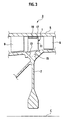
- a rotor blade 1 in accordance with the embodiment of the present invention is installed in a case 5 of a compressor 3 of a gas turbine engine so as to rotate unitarily with the disk 7 around an axial center C as shown in Fig. 3 .
- a plurality of rotor blades 1 are arranged at even intervals in a circumferential direction. In the axial direction, the rotor blades 1 and the stator vanes 9 are alternately arranged.
- Each rotor blade 1 has a blade 11 as a main body thereof.
- the rotor blade 1 has a platform 13 at a proximal end thereof unitarily and also a dovetail 15 at a further proximal end thereof unitarily.
- the blade 11 has a suction side 11a made to be convex and a pressure side 11b made to be concave at an opposite side thereto. More specifically, the blade 11 forms an aerofoil profile at a plane perpendicular to the radial direction.
- the platform 13 is in a rectangular plate-like shape and the platform 13 along with adjacent platforms forms a circumferential face around the axial center C.
- the dovetail 15 is so structured as to engage with the disk 7.
- the distal end of the blade 11 unitarily has a squealer tip 17.
- the squealer tip 17 is a portion which is made thinner than the main body. Its back face 17a is continuous to the suction side 11a and its front face 17b is a face stepped back from the pressure side 11b and curved in leading and trailing directions to be a concave face. Further, the front face 17b of the squealer tip 17 is made to match with a center plane (and an extrapolation thereof; the same will be applied hereinafter). In Fig. 2 , as being cut by the cross sectional face, the center plane is shown as a line L.
- the center plane is a mechanically neutral face which is free from strain even when the blade 11 is deformed to bend.
- matching does not mean perfect matching exclusive of any error, but means and is used as matching to a degree permitting unavoidable error in view of technical and economical views by one skilled in the art.
- the front face 17b and the center plane may be made matched with each other from the leading edge through the trailing edge as shown in Fig. 2B , or alternatively they may be made matched with each other at least at parts thereof except vicinities of the leading edge and the trailing edge as shown in Fig. 2A .
- a leading face 17c and a trailing face 17d of the squealer tip 17 may be made to be continuous to the pressure side 11b.
- the squealer tip 17 reduces possibility of occurrence of cracks in a hard coating thereon. If the squealer tip 17 is made to be too low in height, it is uneasy to carry out coating. If it is made to be too tall, performance as a blade is reduced and cracks in the hard coating may easily occur. Therefore, height of the squealer tip 17 in the radial direction may be from 0.5mm to 4.0mm. Further, a corner of the squealer tip toward the pressure side may be rounded. Radius of the rounded corner may be made greater so as to reduce stress concentration on the angle.
- the front face 17b is coated with the hard coating 19. If the squealer tip is formed in the shape shown in Fig. 2A , the coating 19 may cover not only the front face 17b but also the leading face 17c and the trailing face 17d. Further, the hard coating 19 may cover any faces other than the leading face 17c and the trailing face 17d.
- the hard coating 19 is formed by any coating method such as spraying, and consists essentially of one or more materials selected from the group consisting of WC (tungsten carbide), TiC (titanium carbide), SiC (silicon carbide) so as to have abrasiveness.
- WC tungsten carbide
- TiC titanium carbide
- SiC silicon carbide
- abrasiveness is a quality of abrading an opposite member (the case 5 in this case) which is in frictional contact and in return being protected from deterioration by the frictional contact as the opposite member preferentially wears.
- the hard coating 19 having abrasiveness covers the front face 17b, when the distal end of the rotor blade 1, namely the squealer tip 17, comes into frictional contact with the inner periphery of the case 5 during the compressor 3 is in operation, the inner periphery of the case 5 wears and in return the rotor blade 1 is protected from deterioration by frictional contact.
- hard ceramics such as carbides and nitrides and further ceramics containing abrasive particles such as cubic boron nitride can be exemplified. More particularly, tungsten carbide, titanium carbide and silicon carbide can be exemplified.
- the hard coating 19 may be formed by any method selected from proper coating techniques of spraying, physical vapor deposition (PVD), chemical vapor deposition (CVD), electric spark surface treatment (micro spark coating: MSC) and such. If thickness of the hard coating 19 is too small, the hard coating 19 may likely wear out in a relatively short term or may be hard to be formed without any defects. If the hard coating 19 is too thick, it gives rise to occurrence of cracks caused by a repeating thermal cycle or such. As proper thickness depends on quality of the coating and the quality depends on which coating technique is applied, resultantly the thickness should be determined on which coating technique is applied. In a case where the hard coating 19 is formed by spraying, the thickness is preferably from 0.025mm to 0.15mm.
- the thickness of the coating 19 is preferably from 0.002mm to 0.025mm. Further in a case where the coating is formed by PVD or CVD, the thickness is preferably from 0.002mm to 0.005mm.
- the center plane is nearly free from stretching and compression as the center plane is a mechanically neutral face.
- the front face 17b of the squealer tip 17 is so formed as to at least partly match with the center plane, the hard coating 19 formed on the front face 17b is also nearly free from stretching and compression. Thereby occurrence of cracks in the hard coating 19 caused by vibration-induced fatigue is prevented and accordingly the lifetime of the rotor blade 1 of the compressor is elongated.
- the mechanically neutral plane is made to be the center plane in the aforementioned description
- a geometrically central plane, or any plane or any curved surface having affinity with the neutral or center plane which may be mechanically or geometrically uniquely-definable, may be applied to the plane with which the front face 17b matches in a case where the center plane is uneasy to be defined or machining of the squealer tip 17 along the center plane is uneasy to be carried out.
- a plane or a surface does not accurately match with the mechanically neutral face, as the plane or the surface is sufficiently close thereto and hence stretching and compression are extremely suppressed, an effect that fatigue induced by vibration is suppressed can be enjoyed.
- the blade 11 When the blade 11 vibrates, standing waves having nodes positioned at the leading and trailing edges thereof are likely to be generated. As positions corresponding to antinodes of the standing waves suffer from the greatest stretching and compression, these positions on the hard coating 19 may be susceptible to fatigue. Therefore, when positions corresponding to the antinodes are calculated on the basis of vibration analysis of the blade 11, the positions corresponding to the antinodes may be included in a range where the front face 17b of the squealer tip 17 matches with the center plane of the blade 11.
- the fundamental wave having a longest wavelength which is corresponding to a length from the leading edge to the trailing edge should be primarily taken into consideration, however, the first harmonic, the second harmonic, or any higher mode harmonics may be taken into consideration.
- points respectively corresponding to 1/4 and 3/4 of a chord length from the leading edge to the trailing edge may be regarded as the antinodes and these points may be included in the range where the front face 17b of the squealer tip 17 matches with the center plane of the blade 11.
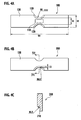
- a metal mass of INCONEL 718 was machined into cold bending fatigue test pieces as shown in Fig. 4(a) . These pieces were finished into a so-called three-triangle finishing of generally used finish marks. Subsequently, both faces of cites referred to the reference numeral 120 were treated with shot peening, and both faces of remaining cites 130 were treated with glass bead peening. Those without a hard coating (test pieces 1), and those coated with a hard coating of TiC on the cites 110 (although only on one of the faces) by MSC (test pieces 2) were prepared.
- test pieces of the identical material and having the identical shape each of which had one of paired narrowed portions machined and thereby reduced into half in thickness as simulating a squealer tip as shown in Fig. 4B , were produced. Those without a hard coating and those with a hard coating of TiC as shown in Fig. 4C were prepared. Cold bending fatigue tests were executed by loading repeating stress of 25Hz in frequency and 680MPa on the four kinds of these test pieces. Results are shown in Table 1.
- Table 1 Fatigue test results Test piece number Simulated squealer tip Hard coating Stress (MPa) Frequency (Hz) Cycle for fracture 1 None None 680 25 769000 2 Formed 217000 3 Formed None 64300 4 Formed 59000
- the fracture lifetime of the test piece with the hard coating is decreased down to about 30 percent of that without the hard coating.
- promotion of fracture of the test piece 2 may be understood as results of that: the hard coating is likely to generate points of origin of cracks because the hard coating is harder than INCONEL 718 as the base body and exists at the surface where stretching and compression are the most severe; and these cracks extend into the base body.
- whether existence or non-existence of the hard coating in the test pieces having simulated squealer tips causes small difference in the fracture lifetime.
Landscapes
- Engineering & Computer Science (AREA)
- Mechanical Engineering (AREA)
- General Engineering & Computer Science (AREA)
- Structures Of Non-Positive Displacement Pumps (AREA)
- Turbine Rotor Nozzle Sealing (AREA)
- Other Surface Treatments For Metallic Materials (AREA)
Abstract
Description
- The present invention relates to a rotor of a compressor applied to a gas turbine engine.
- Gas turbine engines are employed as power sources of jet airplanes and have compressors each having stators and rotors arranged axially alternately. A rotor has a plurality of rotor blades arranged at even intervals in a circumferential direction, each of which is directed obliquely to both the front direction and the rotating direction so as to compress air aftward by rotation thereof. In each blade, a face directed forward is to suck air and therefore referred to as a suction side and another face directed aftward is to compress air and referred to as a pressure side. To increase a compression effect, the suction side is made convex and the pressure side is made concave, more specifically each blade has a so-called aerofoil profile.
- A distal end of each blade is often coated with a hard coating having abrasiveness as it has frictional contact with an inner face of a case of the compressor. Here, the term "abrasiveness" with respect to a member means a quality of abrading an opposite member (the case of the compressor in this case) which is in frictional contact with the member. Because of the abrasiveness of the hard coating, as the opposite member preferentially wears in comparison between the distal end and the opposite member, the distal end is protected from deterioration by frictional contact.
Japanese Patent Application Laid-open No. 2000-345809 - The blades of the rotor are given a repeating vibration during operation of the compressor. The repeating load caused by the repeating vibration generates repeating stretching and compressive stresses on both the suction side and the pressure side of each blade. These repeating stresses may cause occurrence of fatigue cracks in the main body of the blade or the hard coating coated thereon. The cracks in the blade or the hard coating are likely to extend over the entire blade and therefore cause severe reduction of the fatigue lifetime of the blade. The present invention has an object to prevent cracks reduced by vibration and resultantly provide a rotor blade of a compressor having an improved lifetime.
- The inventors had carried out intent studies on repeating stretching and compressive stresses and points of origin of cracks to achieve the above object. As a result, the inventors made findings that hardness of the hard coating causes cracks and also the hard coating is likely to be points of origin of cracks because the coating is disposed at an utmost surface on the blade where repeating stretching and compression are the most severe. Finally, the inventors reached a conclusion that to form a face under substantially no stress at a distal end of the blade and to coat a hard coating on the face may lead to a prominently improved fatigue lifetime.
- According to an aspect of the present invention, a rotor applied to a compressor of a gas turbine engine is provided with a blade having a suction side and a pressure side; a squealer tip formed in a unitary body with a distal end of the blade, the squealer tip including a first face continuous to the suction side and a second face matching with a center plane of the blade; and a coating covering the second face.
- Preferably, the squealer tip further has a leading face and a trailing face, both of which are continuous to the second face and do not match with the center plane of the blade, and the coating further covers the leading face and the trailing face. More preferably, the center face comprises a mechanically neutral face. Further preferably, the second face includes points respectively correspondent to 1/4 and 3/4 of a chord length from a leading edge to a trailing edge of the blade. Still preferably, the coating includes any material selected from the group of tungsten carbide, titanium carbide and silicon carbide. Alternatively preferably, the coating is formed by any method selected from the group of a spraying method, a physical vapor deposition method, a chemical vapor deposition method and an electric spark surface treatment method.
-
-
Fig. 1 is a perspective view of a rotor blade of a compressor in accordance with an embodiment of the present invention; -
Figs. 2A and 2B are cross sectional views of a part ranging from a distal end to the middle of the rotor blade; -
Fig. 3 is a cross sectional view of a part of the compressor including the rotor blade; and -
Figs. 4A-4C are outlines of a fatigue test piece. - An embodiment of the present invention will be described hereinafter with reference to
Figs. 1 to 3 . Throughout the drawings, the specification and claims, a distal end and a proximal end of the rotor blade are respectively defined as radially outer and inner ends with respect to an axis of the compressor. Further, the fore and the aft are respectively defined as directions corresponding to the upstream and the downstream in an air flow through the compressor. InFig. 3 , the fore is shown as the left and the aft as the right. - A rotor blade 1 in accordance with the embodiment of the present invention is installed in a
case 5 of acompressor 3 of a gas turbine engine so as to rotate unitarily with the disk 7 around an axial center C as shown inFig. 3 . A plurality of rotor blades 1 are arranged at even intervals in a circumferential direction. In the axial direction, the rotor blades 1 and the stator vanes 9 are alternately arranged. - Each rotor blade 1 has a
blade 11 as a main body thereof. The rotor blade 1 has aplatform 13 at a proximal end thereof unitarily and also adovetail 15 at a further proximal end thereof unitarily. Theblade 11 has asuction side 11a made to be convex and apressure side 11b made to be concave at an opposite side thereto. More specifically, theblade 11 forms an aerofoil profile at a plane perpendicular to the radial direction. Theplatform 13 is in a rectangular plate-like shape and theplatform 13 along with adjacent platforms forms a circumferential face around the axial center C. Thedovetail 15 is so structured as to engage with the disk 7. - As shown in
Figs. 1 and2 , the distal end of theblade 11 unitarily has asquealer tip 17. Thesquealer tip 17 is a portion which is made thinner than the main body. Itsback face 17a is continuous to thesuction side 11a and itsfront face 17b is a face stepped back from thepressure side 11b and curved in leading and trailing directions to be a concave face. Further, thefront face 17b of thesquealer tip 17 is made to match with a center plane (and an extrapolation thereof; the same will be applied hereinafter). InFig. 2 , as being cut by the cross sectional face, the center plane is shown as a line L. The center plane is a mechanically neutral face which is free from strain even when theblade 11 is deformed to bend. Meanwhile, throughout the specification and claims, the term "matching" does not mean perfect matching exclusive of any error, but means and is used as matching to a degree permitting unavoidable error in view of technical and economical views by one skilled in the art. - The
front face 17b and the center plane may be made matched with each other from the leading edge through the trailing edge as shown inFig. 2B , or alternatively they may be made matched with each other at least at parts thereof except vicinities of the leading edge and the trailing edge as shown inFig. 2A . In a case ofFig. 2A , a leadingface 17c and a trailingface 17d of thesquealer tip 17 may be made to be continuous to thepressure side 11b. - The
squealer tip 17 reduces possibility of occurrence of cracks in a hard coating thereon. If thesquealer tip 17 is made to be too low in height, it is uneasy to carry out coating. If it is made to be too tall, performance as a blade is reduced and cracks in the hard coating may easily occur. Therefore, height of thesquealer tip 17 in the radial direction may be from 0.5mm to 4.0mm. Further, a corner of the squealer tip toward the pressure side may be rounded. Radius of the rounded corner may be made greater so as to reduce stress concentration on the angle. - The
front face 17b is coated with thehard coating 19. If the squealer tip is formed in the shape shown inFig. 2A , thecoating 19 may cover not only thefront face 17b but also the leadingface 17c and the trailingface 17d. Further, thehard coating 19 may cover any faces other than the leadingface 17c and the trailingface 17d. - The
hard coating 19 is formed by any coating method such as spraying, and consists essentially of one or more materials selected from the group consisting of WC (tungsten carbide), TiC (titanium carbide), SiC (silicon carbide) so as to have abrasiveness. - Meanwhile, "abrasiveness" is a quality of abrading an opposite member (the
case 5 in this case) which is in frictional contact and in return being protected from deterioration by the frictional contact as the opposite member preferentially wears. As thehard coating 19 having abrasiveness covers thefront face 17b, when the distal end of the rotor blade 1, namely thesquealer tip 17, comes into frictional contact with the inner periphery of thecase 5 during thecompressor 3 is in operation, the inner periphery of thecase 5 wears and in return the rotor blade 1 is protected from deterioration by frictional contact. As materials having abrasiveness, hard ceramics such as carbides and nitrides and further ceramics containing abrasive particles such as cubic boron nitride can be exemplified. More particularly, tungsten carbide, titanium carbide and silicon carbide can be exemplified. - The
hard coating 19 may be formed by any method selected from proper coating techniques of spraying, physical vapor deposition (PVD), chemical vapor deposition (CVD), electric spark surface treatment (micro spark coating: MSC) and such. If thickness of thehard coating 19 is too small, thehard coating 19 may likely wear out in a relatively short term or may be hard to be formed without any defects. If thehard coating 19 is too thick, it gives rise to occurrence of cracks caused by a repeating thermal cycle or such. As proper thickness depends on quality of the coating and the quality depends on which coating technique is applied, resultantly the thickness should be determined on which coating technique is applied. In a case where thehard coating 19 is formed by spraying, the thickness is preferably from 0.025mm to 0.15mm. Alternatively in a case where MSC is used for forming thehard coating 19, the thickness of thecoating 19 is preferably from 0.002mm to 0.025mm. Further in a case where the coating is formed by PVD or CVD, the thickness is preferably from 0.002mm to 0.005mm. - As described above, even when repeating stretching and compressive stresses generated by vibration of the rotor blade 1 acts on the
blade 11, the center plane is nearly free from stretching and compression as the center plane is a mechanically neutral face. As thefront face 17b of thesquealer tip 17 is so formed as to at least partly match with the center plane, thehard coating 19 formed on thefront face 17b is also nearly free from stretching and compression. Thereby occurrence of cracks in thehard coating 19 caused by vibration-induced fatigue is prevented and accordingly the lifetime of the rotor blade 1 of the compressor is elongated. - The aforementioned embodiment can be modified as the needs arise. For example, whereas the mechanically neutral plane is made to be the center plane in the aforementioned description, a geometrically central plane, or any plane or any curved surface having affinity with the neutral or center plane, which may be mechanically or geometrically uniquely-definable, may be applied to the plane with which the
front face 17b matches in a case where the center plane is uneasy to be defined or machining of thesquealer tip 17 along the center plane is uneasy to be carried out. Even though such a plane or a surface does not accurately match with the mechanically neutral face, as the plane or the surface is sufficiently close thereto and hence stretching and compression are extremely suppressed, an effect that fatigue induced by vibration is suppressed can be enjoyed. - When the
blade 11 vibrates, standing waves having nodes positioned at the leading and trailing edges thereof are likely to be generated. As positions corresponding to antinodes of the standing waves suffer from the greatest stretching and compression, these positions on thehard coating 19 may be susceptible to fatigue. Therefore, when positions corresponding to the antinodes are calculated on the basis of vibration analysis of theblade 11, the positions corresponding to the antinodes may be included in a range where thefront face 17b of thesquealer tip 17 matches with the center plane of theblade 11. Among the standing waves, the fundamental wave having a longest wavelength which is corresponding to a length from the leading edge to the trailing edge should be primarily taken into consideration, however, the first harmonic, the second harmonic, or any higher mode harmonics may be taken into consideration. Further in a case where the vibration analysis is uneasy to be carried out because of difficulty caused by a shape, points respectively corresponding to 1/4 and 3/4 of a chord length from the leading edge to the trailing edge may be regarded as the antinodes and these points may be included in the range where thefront face 17b of thesquealer tip 17 matches with the center plane of theblade 11. - To demonstrate the effects, the following tests had been carried out.
- A metal mass of INCONEL 718 was machined into cold bending fatigue test pieces as shown in
Fig. 4(a) . These pieces were finished into a so-called three-triangle finishing of generally used finish marks. Subsequently, both faces of cites referred to thereference numeral 120 were treated with shot peening, and both faces of remaining cites 130 were treated with glass bead peening. Those without a hard coating (test pieces 1), and those coated with a hard coating of TiC on the cites 110 (although only on one of the faces) by MSC (test pieces 2) were prepared. Further, test pieces of the identical material and having the identical shape, each of which had one of paired narrowed portions machined and thereby reduced into half in thickness as simulating a squealer tip as shown inFig. 4B , were produced. Those without a hard coating and those with a hard coating of TiC as shown inFig. 4C were prepared. Cold bending fatigue tests were executed by loading repeating stress of 25Hz in frequency and 680MPa on the four kinds of these test pieces. Results are shown in Table 1.Table 1 Fatigue test results Test piece number Simulated squealer tip Hard coating Stress (MPa) Frequency (Hz) Cycle for fracture 1 None None 680 25 769000 2 Formed 217000 3 Formed None 64300 4 Formed 59000 - As being understood from comparison between the test pieces 1 and 2, the fracture lifetime of the test piece with the hard coating is decreased down to about 30 percent of that without the hard coating. On the basis of these results, promotion of fracture of the test piece 2 may be understood as results of that: the hard coating is likely to generate points of origin of cracks because the hard coating is harder than INCONEL 718 as the base body and exists at the surface where stretching and compression are the most severe; and these cracks extend into the base body. On the other hand, as being understood from comparison between the
test pieces 3 and 4, whether existence or non-existence of the hard coating in the test pieces having simulated squealer tips causes small difference in the fracture lifetime. These results can be understood as meaning that, if the hard coating is coated on the squealer tips, cracks are unlikely generated in the hard coating because the squealer tips are nearly free from stretching and compression, and therefore the crack lifetimes of the test pieces as a whole are not affected. Meanwhile, the fact that the crack lifetimes of thetest pieces 3 and 4 are shorter than those of the test pieces 1 and 2 is caused by that the shape of the test pieces is too severe in view of fatigue, and has no relation with the nature of the present invention. - Although the invention has been described above by reference to certain embodiments of the invention, the invention is not limited to the embodiments described above. Modifications and variations of the embodiments described above will occur to those skilled in the art, in light of the above teachings.
Claims (6)
- A rotor (1) applied to a compressor (3) of a gas turbine engine, comprising:a blade (11) having a suction side (11a) and a pressure side (11b) ;a squealer tip (17) formed in a unitary body with a distal end of the blade (11), the squealer tip (17) including a first face (17a) continuous to the suction side (11a) and a second face (17b) matching with a center plane of the blade (11); anda coating (19) covering the second face (17b).
- The rotor (1) of claim 1, wherein the squealer tip (17) further includes a leading face (17c) and a trailing face (17d), both the leading face (17c) and the leading face (17d) being continuous to the second face (17b) and not matching with the center plane of the blade (11), and the coating (19) further covers the leading face (17c) and the trailing face (17d) .
- The rotor (1) of claim 1 or 2, wherein the center face comprises a mechanically neutral face.
- The rotor (1) of any of claims 1 to 3, wherein the second face (17b) includes points respectively correspondent to 1/4 and 3/4 of a chord length from a leading edge to a trailing edge of the blade (11).
- The rotor (1) of any of claims 1 to 4, wherein the coating (19) includes any material selected from the group of tungsten carbide, titanium carbide and silicon carbide.
- The rotor (1) of any of claims 1 to 5, wherein the coating (19) is formed by any method selected from the group of a spraying method, a physical vapor deposition method, a chemical vapor deposition method and an electric spark surface treatment method.
Applications Claiming Priority (1)
| Application Number | Priority Date | Filing Date | Title |
|---|---|---|---|
| JP2006317489A JP4830812B2 (en) | 2006-11-24 | 2006-11-24 | Compressor blade |
Publications (3)
| Publication Number | Publication Date |
|---|---|
| EP1930547A2 true EP1930547A2 (en) | 2008-06-11 |
| EP1930547A3 EP1930547A3 (en) | 2010-03-10 |
| EP1930547B1 EP1930547B1 (en) | 2016-03-30 |
Family
ID=39155207
Family Applications (1)
| Application Number | Title | Priority Date | Filing Date |
|---|---|---|---|
| EP07254540.3A Active EP1930547B1 (en) | 2006-11-24 | 2007-11-22 | Compressor blade for a gas turbine engine |
Country Status (3)
| Country | Link |
|---|---|
| US (1) | US8366400B2 (en) |
| EP (1) | EP1930547B1 (en) |
| JP (1) | JP4830812B2 (en) |
Cited By (8)
| Publication number | Priority date | Publication date | Assignee | Title |
|---|---|---|---|---|
| WO2011002570A1 (en) * | 2009-06-30 | 2011-01-06 | General Electric Company | Rotor blade and method for reducing tip rub loading |
| WO2011038966A1 (en) | 2009-09-30 | 2011-04-07 | Siemens Aktiengesellschaft | Airfoil and corresponding guide vane, blade, gas turbine and turbomaschine |
| WO2011038971A1 (en) | 2009-09-30 | 2011-04-07 | Siemens Aktiengesellschaft | Airfoil and corresponding guide vane, blade, gas turbine and turbomaschine |
| US8167572B2 (en) | 2008-07-14 | 2012-05-01 | Pratt & Whitney Canada Corp. | Dynamically tuned turbine blade growth pocket |
| EP2696031A1 (en) * | 2012-08-09 | 2014-02-12 | MTU Aero Engines GmbH | Blade for a flow machine engine and corresponding flow machine engine. |
| US8657570B2 (en) | 2009-06-30 | 2014-02-25 | General Electric Company | Rotor blade with reduced rub loading |
| US8662834B2 (en) | 2009-06-30 | 2014-03-04 | General Electric Company | Method for reducing tip rub loading |
| EP2937514A1 (en) * | 2014-04-22 | 2015-10-28 | United Technologies Corporation | Gas turbine engine turbine blade tip with coated recess |
Families Citing this family (13)
| Publication number | Priority date | Publication date | Assignee | Title |
|---|---|---|---|---|
| US8092178B2 (en) * | 2008-11-28 | 2012-01-10 | Pratt & Whitney Canada Corp. | Turbine blade for a gas turbine engine |
| JP4654305B2 (en) * | 2009-05-15 | 2011-03-16 | 三井造船株式会社 | Blast furnace blower |
| JP4654304B2 (en) * | 2009-05-15 | 2011-03-16 | 三井造船株式会社 | Blast furnace blower |
| EP2530330B1 (en) * | 2011-06-01 | 2016-05-25 | MTU Aero Engines AG | Rotor blade for the compressor of a turbo engine, compressor and turbo machine |
| US20130236325A1 (en) * | 2012-03-08 | 2013-09-12 | Hamilton Sundstrand Corporation | Blade tip profile |
| DE112013001507T5 (en) * | 2012-04-23 | 2015-03-19 | Borgwarner Inc. | Turbocharger blade with outline edge stage and turbocharger containing it |
| US10472934B2 (en) | 2015-05-21 | 2019-11-12 | Novatek Ip, Llc | Downhole transducer assembly |
| US10113399B2 (en) | 2015-05-21 | 2018-10-30 | Novatek Ip, Llc | Downhole turbine assembly |
| US10190595B2 (en) | 2015-09-15 | 2019-01-29 | General Electric Company | Gas turbine engine blade platform modification |
| US10927647B2 (en) | 2016-11-15 | 2021-02-23 | Schlumberger Technology Corporation | Systems and methods for directing fluid flow |
| US10439474B2 (en) * | 2016-11-16 | 2019-10-08 | Schlumberger Technology Corporation | Turbines and methods of generating electricity |
| US11168702B2 (en) * | 2017-08-10 | 2021-11-09 | Raytheon Technologies Corporation | Rotating airfoil with tip pocket |
| CN119021904B (en) * | 2024-10-12 | 2025-10-21 | 西北工业大学 | Axial flow compressor rotor blade with blade tip guide structure and guide method thereof |
Family Cites Families (29)
| Publication number | Priority date | Publication date | Assignee | Title |
|---|---|---|---|---|
| US899319A (en) * | 1906-10-08 | 1908-09-22 | Charles Algernon Parsons | Turbine. |
| JPS5143305Y2 (en) * | 1972-12-15 | 1976-10-21 | ||
| JPS4998602A (en) | 1973-01-24 | 1974-09-18 | ||
| US4390320A (en) * | 1980-05-01 | 1983-06-28 | General Electric Company | Tip cap for a rotor blade and method of replacement |
| US4744725A (en) * | 1984-06-25 | 1988-05-17 | United Technologies Corporation | Abrasive surfaced article for high temperature service |
| FR2615254A1 (en) * | 1987-05-13 | 1988-11-18 | Snecma | MOBILE BLOWER BLADE COMPRISING AN END END |
| FR2623569A1 (en) * | 1987-11-19 | 1989-05-26 | Snecma | VANE OF COMPRESSOR WITH DISSYMMETRIC LETTLE LETCHES |
| US4878810A (en) * | 1988-05-20 | 1989-11-07 | Westinghouse Electric Corp. | Turbine blades having alternating resonant frequencies |
| US5286168A (en) * | 1992-01-31 | 1994-02-15 | Westinghouse Electric Corp. | Freestanding mixed tuned blade |
| GB2310897B (en) * | 1993-10-15 | 1998-05-13 | United Technologies Corp | Method and apparatus for reducing stress on the tips of turbine or compressor blades |
| US5476363A (en) * | 1993-10-15 | 1995-12-19 | Charles E. Sohl | Method and apparatus for reducing stress on the tips of turbine or compressor blades |
| US5456576A (en) * | 1994-08-31 | 1995-10-10 | United Technologies Corporation | Dynamic control of tip clearance |
| JPH08284884A (en) * | 1995-04-17 | 1996-10-29 | Mitsubishi Heavy Ind Ltd | Fluid machinery |
| US6190124B1 (en) * | 1997-11-26 | 2001-02-20 | United Technologies Corporation | Columnar zirconium oxide abrasive coating for a gas turbine engine seal system |
| US6206642B1 (en) * | 1998-12-17 | 2001-03-27 | United Technologies Corporation | Compressor blade for a gas turbine engine |
| US6059530A (en) * | 1998-12-21 | 2000-05-09 | General Electric Company | Twin rib turbine blade |
| JP2000345809A (en) | 1999-06-02 | 2000-12-12 | Ishikawajima Harima Heavy Ind Co Ltd | Gas turbine engine |
| US6422821B1 (en) * | 2001-01-09 | 2002-07-23 | General Electric Company | Method and apparatus for reducing turbine blade tip temperatures |
| JP2002256808A (en) * | 2001-02-28 | 2002-09-11 | Mitsubishi Heavy Ind Ltd | Combustion engine, gas turbine and grinding layer |
| US7063250B2 (en) * | 2001-05-31 | 2006-06-20 | Mitsubishi Heavy Industries, Ltd. | Coating forming method and coating forming material, and abrasive coating forming sheet |
| JP2003148103A (en) * | 2001-11-09 | 2003-05-21 | Mitsubishi Heavy Ind Ltd | Turbine and its manufacturing method |
| US6761539B2 (en) * | 2002-07-24 | 2004-07-13 | Ventilatoren Sirocco Howden B.V. | Rotor blade with a reduced tip |
| JP4096301B2 (en) * | 2002-10-09 | 2008-06-04 | 株式会社Ihi | Rotor blade and coating method thereof |
| CA2483528C (en) | 2002-10-09 | 2015-07-21 | Ishikawajima-Harima Heavy Industries Co., Ltd. | Rotating member and method for coating the same |
| US6976826B2 (en) * | 2003-05-29 | 2005-12-20 | Pratt & Whitney Canada Corp. | Turbine blade dimple |
| EP1624192A1 (en) * | 2004-08-06 | 2006-02-08 | Siemens Aktiengesellschaft | Impeller blade for axial compressor |
| DE102005006414A1 (en) * | 2005-02-12 | 2006-08-24 | Mtu Aero Engines Gmbh | A method of machining an integrally bladed rotor |
| FR2893268B1 (en) * | 2005-11-15 | 2008-02-08 | Snecma Sa | METHOD OF MAKING A REBORD LOCATED AT THE FREE END OF A DAWN, DAWN OBTAINED BY THIS PROCESS AND TURBOMACHINE EQUIPPED WITH SAID DARK |
| JP4998602B2 (en) | 2010-06-21 | 2012-08-15 | コニカミノルタビジネステクノロジーズ株式会社 | Developing device and image forming apparatus |
-
2006
- 2006-11-24 JP JP2006317489A patent/JP4830812B2/en not_active Expired - Fee Related
-
2007
- 2007-11-22 EP EP07254540.3A patent/EP1930547B1/en active Active
- 2007-11-23 US US11/944,560 patent/US8366400B2/en not_active Expired - Fee Related
Cited By (12)
| Publication number | Priority date | Publication date | Assignee | Title |
|---|---|---|---|---|
| US8167572B2 (en) | 2008-07-14 | 2012-05-01 | Pratt & Whitney Canada Corp. | Dynamically tuned turbine blade growth pocket |
| US8499449B2 (en) | 2008-07-14 | 2013-08-06 | Pratt & Whitney Canada Corp. | Method for manufacturing a turbine blade |
| WO2011002570A1 (en) * | 2009-06-30 | 2011-01-06 | General Electric Company | Rotor blade and method for reducing tip rub loading |
| US8657570B2 (en) | 2009-06-30 | 2014-02-25 | General Electric Company | Rotor blade with reduced rub loading |
| US8662834B2 (en) | 2009-06-30 | 2014-03-04 | General Electric Company | Method for reducing tip rub loading |
| WO2011038966A1 (en) | 2009-09-30 | 2011-04-07 | Siemens Aktiengesellschaft | Airfoil and corresponding guide vane, blade, gas turbine and turbomaschine |
| WO2011038971A1 (en) | 2009-09-30 | 2011-04-07 | Siemens Aktiengesellschaft | Airfoil and corresponding guide vane, blade, gas turbine and turbomaschine |
| EP2309098A1 (en) | 2009-09-30 | 2011-04-13 | Siemens Aktiengesellschaft | Airfoil and corresponding guide vane, blade, gas turbine and turbomachine |
| EP2309097A1 (en) | 2009-09-30 | 2011-04-13 | Siemens Aktiengesellschaft | Airfoil and corresponding guide vane, blade, gas turbine and turbomachine |
| EP2696031A1 (en) * | 2012-08-09 | 2014-02-12 | MTU Aero Engines GmbH | Blade for a flow machine engine and corresponding flow machine engine. |
| US9399918B2 (en) | 2012-08-09 | 2016-07-26 | Mtu Aero Engines Gmbh | Blade for a continuous-flow machine and a continuous-flow machine |
| EP2937514A1 (en) * | 2014-04-22 | 2015-10-28 | United Technologies Corporation | Gas turbine engine turbine blade tip with coated recess |
Also Published As
| Publication number | Publication date |
|---|---|
| US8366400B2 (en) | 2013-02-05 |
| US20080226460A1 (en) | 2008-09-18 |
| EP1930547A3 (en) | 2010-03-10 |
| JP2008128198A (en) | 2008-06-05 |
| EP1930547B1 (en) | 2016-03-30 |
| JP4830812B2 (en) | 2011-12-07 |
Similar Documents
| Publication | Publication Date | Title |
|---|---|---|
| EP1930547B1 (en) | Compressor blade for a gas turbine engine | |
| US5476363A (en) | Method and apparatus for reducing stress on the tips of turbine or compressor blades | |
| JP5579965B2 (en) | Apparatus for manufacturing a rotor assembly | |
| US8657570B2 (en) | Rotor blade with reduced rub loading | |
| US8662834B2 (en) | Method for reducing tip rub loading | |
| EP2423436A2 (en) | Airfoil shape for compressor | |
| US10472729B2 (en) | Abrasive tip blade manufacture methods | |
| EP3184746A1 (en) | Mistuned fan | |
| US20160069195A1 (en) | Rotary blade tip | |
| JP2002213205A (en) | Gas turbine blade with platform relief | |
| US7524165B2 (en) | Control lever for the angular setting of a stator blade in a turboshaft engine | |
| US9297259B2 (en) | Compressor blade | |
| JP2008163951A (en) | Method and apparatus for enhancing airfoil fatigue notch performance | |
| EP1175956B1 (en) | Metallic article with integral end band under compression and method for making | |
| CN105275500B (en) | Fan blade tip as cutting element | |
| US20070077149A1 (en) | Compressor blade with a chamfered tip | |
| JP5628307B2 (en) | Rotor blade and method for reducing tip friction load | |
| KR20170027832A (en) | Steam turbine rotor blade, method for manufacturing steam turbine rotor blade, and steam turbine | |
| JP2000345809A (en) | Gas turbine engine | |
| GB2310897A (en) | Reducing stress on the tips of turbine or compressor blades | |
| KR102734168B1 (en) | Airfoil profile | |
| CN104039507A (en) | Method of surface treatment for dovetail in gas turbine engine fan blade | |
| US20220380926A1 (en) | Method for coating a component | |
| US20060280612A1 (en) | Metallic article with integral end band under compression | |
| CN102536889A (en) | Compressor blade with flexible tip elements and process therefor |
Legal Events
| Date | Code | Title | Description |
|---|---|---|---|
| PUAI | Public reference made under article 153(3) epc to a published international application that has entered the european phase |
Free format text: ORIGINAL CODE: 0009012 |
|
| 17P | Request for examination filed |
Effective date: 20071203 |
|
| AK | Designated contracting states |
Kind code of ref document: A2 Designated state(s): AT BE BG CH CY CZ DE DK EE ES FI FR GB GR HU IE IS IT LI LT LU LV MC MT NL PL PT RO SE SI SK TR |
|
| AX | Request for extension of the european patent |
Extension state: AL BA HR MK RS |
|
| PUAL | Search report despatched |
Free format text: ORIGINAL CODE: 0009013 |
|
| AK | Designated contracting states |
Kind code of ref document: A3 Designated state(s): AT BE BG CH CY CZ DE DK EE ES FI FR GB GR HU IE IS IT LI LT LU LV MC MT NL PL PT RO SE SI SK TR |
|
| AX | Request for extension of the european patent |
Extension state: AL BA HR MK RS |
|
| 17Q | First examination report despatched |
Effective date: 20100813 |
|
| AKX | Designation fees paid |
Designated state(s): DE FR GB |
|
| GRAP | Despatch of communication of intention to grant a patent |
Free format text: ORIGINAL CODE: EPIDOSNIGR1 |
|
| INTG | Intention to grant announced |
Effective date: 20151013 |
|
| RIN1 | Information on inventor provided before grant (corrected) |
Inventor name: FUJIMURA, TETSUJI Inventor name: WATANABE, MITSUTOSHI Inventor name: OCHIAI, HIROYUKI Inventor name: FURUKAWA, TAKASHI |
|
| GRAS | Grant fee paid |
Free format text: ORIGINAL CODE: EPIDOSNIGR3 |
|
| GRAA | (expected) grant |
Free format text: ORIGINAL CODE: 0009210 |
|
| AK | Designated contracting states |
Kind code of ref document: B1 Designated state(s): DE FR GB |
|
| REG | Reference to a national code |
Ref country code: GB Ref legal event code: FG4D |
|
| REG | Reference to a national code |
Ref country code: DE Ref legal event code: R096 Ref document number: 602007045524 Country of ref document: DE |
|
| REG | Reference to a national code |
Ref country code: DE Ref legal event code: R097 Ref document number: 602007045524 Country of ref document: DE |
|
| PLBE | No opposition filed within time limit |
Free format text: ORIGINAL CODE: 0009261 |
|
| STAA | Information on the status of an ep patent application or granted ep patent |
Free format text: STATUS: NO OPPOSITION FILED WITHIN TIME LIMIT |
|
| 26N | No opposition filed |
Effective date: 20170103 |
|
| REG | Reference to a national code |
Ref country code: DE Ref legal event code: R119 Ref document number: 602007045524 Country of ref document: DE |
|
| REG | Reference to a national code |
Ref country code: FR Ref legal event code: ST Effective date: 20170731 |
|
| PG25 | Lapsed in a contracting state [announced via postgrant information from national office to epo] |
Ref country code: FR Free format text: LAPSE BECAUSE OF NON-PAYMENT OF DUE FEES Effective date: 20161130 |
|
| PG25 | Lapsed in a contracting state [announced via postgrant information from national office to epo] |
Ref country code: DE Free format text: LAPSE BECAUSE OF NON-PAYMENT OF DUE FEES Effective date: 20170601 |
|
| PGFP | Annual fee paid to national office [announced via postgrant information from national office to epo] |
Ref country code: GB Payment date: 20251001 Year of fee payment: 19 |