EP1930040A1 - Prefilled syringe - Google Patents
Prefilled syringe Download PDFInfo
- Publication number
- EP1930040A1 EP1930040A1 EP06796542A EP06796542A EP1930040A1 EP 1930040 A1 EP1930040 A1 EP 1930040A1 EP 06796542 A EP06796542 A EP 06796542A EP 06796542 A EP06796542 A EP 06796542A EP 1930040 A1 EP1930040 A1 EP 1930040A1
- Authority
- EP
- European Patent Office
- Prior art keywords
- syringe
- disc
- prefilled syringe
- shaped
- drug
- Prior art date
- Legal status (The legal status is an assumption and is not a legal conclusion. Google has not performed a legal analysis and makes no representation as to the accuracy of the status listed.)
- Granted
Links
Images




Classifications
-
- A—HUMAN NECESSITIES
- A61—MEDICAL OR VETERINARY SCIENCE; HYGIENE
- A61M—DEVICES FOR INTRODUCING MEDIA INTO, OR ONTO, THE BODY; DEVICES FOR TRANSDUCING BODY MEDIA OR FOR TAKING MEDIA FROM THE BODY; DEVICES FOR PRODUCING OR ENDING SLEEP OR STUPOR
- A61M5/00—Devices for bringing media into the body in a subcutaneous, intra-vascular or intramuscular way; Accessories therefor, e.g. filling or cleaning devices, arm-rests
- A61M5/178—Syringes
- A61M5/28—Syringe ampoules or carpules, i.e. ampoules or carpules provided with a needle
-
- A—HUMAN NECESSITIES
- A61—MEDICAL OR VETERINARY SCIENCE; HYGIENE
- A61M—DEVICES FOR INTRODUCING MEDIA INTO, OR ONTO, THE BODY; DEVICES FOR TRANSDUCING BODY MEDIA OR FOR TAKING MEDIA FROM THE BODY; DEVICES FOR PRODUCING OR ENDING SLEEP OR STUPOR
- A61M5/00—Devices for bringing media into the body in a subcutaneous, intra-vascular or intramuscular way; Accessories therefor, e.g. filling or cleaning devices, arm-rests
- A61M5/178—Syringes
- A61M5/31—Details
- A61M2005/3103—Leak prevention means for distal end of syringes, i.e. syringe end for mounting a needle
- A61M2005/3104—Caps for syringes without needle
-
- A—HUMAN NECESSITIES
- A61—MEDICAL OR VETERINARY SCIENCE; HYGIENE
- A61M—DEVICES FOR INTRODUCING MEDIA INTO, OR ONTO, THE BODY; DEVICES FOR TRANSDUCING BODY MEDIA OR FOR TAKING MEDIA FROM THE BODY; DEVICES FOR PRODUCING OR ENDING SLEEP OR STUPOR
- A61M5/00—Devices for bringing media into the body in a subcutaneous, intra-vascular or intramuscular way; Accessories therefor, e.g. filling or cleaning devices, arm-rests
- A61M5/178—Syringes
- A61M5/31—Details
- A61M2005/3117—Means preventing contamination of the medicament compartment of a syringe
-
- A—HUMAN NECESSITIES
- A61—MEDICAL OR VETERINARY SCIENCE; HYGIENE
- A61M—DEVICES FOR INTRODUCING MEDIA INTO, OR ONTO, THE BODY; DEVICES FOR TRANSDUCING BODY MEDIA OR FOR TAKING MEDIA FROM THE BODY; DEVICES FOR PRODUCING OR ENDING SLEEP OR STUPOR
- A61M5/00—Devices for bringing media into the body in a subcutaneous, intra-vascular or intramuscular way; Accessories therefor, e.g. filling or cleaning devices, arm-rests
- A61M5/001—Apparatus specially adapted for cleaning or sterilising syringes or needles
-
- A—HUMAN NECESSITIES
- A61—MEDICAL OR VETERINARY SCIENCE; HYGIENE
- A61M—DEVICES FOR INTRODUCING MEDIA INTO, OR ONTO, THE BODY; DEVICES FOR TRANSDUCING BODY MEDIA OR FOR TAKING MEDIA FROM THE BODY; DEVICES FOR PRODUCING OR ENDING SLEEP OR STUPOR
- A61M5/00—Devices for bringing media into the body in a subcutaneous, intra-vascular or intramuscular way; Accessories therefor, e.g. filling or cleaning devices, arm-rests
- A61M5/002—Packages specially adapted therefor, e.g. for syringes or needles, kits for diabetics
-
- A—HUMAN NECESSITIES
- A61—MEDICAL OR VETERINARY SCIENCE; HYGIENE
- A61M—DEVICES FOR INTRODUCING MEDIA INTO, OR ONTO, THE BODY; DEVICES FOR TRANSDUCING BODY MEDIA OR FOR TAKING MEDIA FROM THE BODY; DEVICES FOR PRODUCING OR ENDING SLEEP OR STUPOR
- A61M5/00—Devices for bringing media into the body in a subcutaneous, intra-vascular or intramuscular way; Accessories therefor, e.g. filling or cleaning devices, arm-rests
- A61M5/178—Syringes
- A61M5/31—Details
- A61M5/3145—Filters incorporated in syringes
Definitions
- the present invention relates to a syringe (injection syringe) and particularly relates to a prefilled syringe that is already filled with a drug and is capable of injecting a patient at once simply by the fitting of an injection needle.
- prefilled syringes where a syringe barrel of an injection syringe is filled with a drug in advance are well-known.
- Such prefilled syringes are equipped with a nozzle for fitting an injection needle at one end of a syringe barrel constituting a body of the syringe.
- an opening is provided where a plunger having a gasket at a tip of a plunger rod can be freely moved backwards and forwards.
- the nozzle is usually covered over with a cap made of rubber in order to prevent leakage of the drug.
- the entire item is then blister-packed or pillow-packed with the plunger installed.
- Injection syringes prefilled with a drug where a nozzle covered with a cap is then covered with a heat-shrinkable resin film (shrink film) in order to prevent the cap from coming off as well as in order to prevent the filled drug from being tampered with have also been the subject of applications (for example, refer to patent document 1).
- a heat-shrinkable resin film shrink film
- the syringe is made of plastic, it is necessary to store the syringe in barrier packing material having gas barrier properties in order to suppress deterioration of the drug filling the syringe barrel.
- the drug filling the syringe barrel does not degrade because of the gas barrier properties.
- the prefilled syringes are usually removed from the packaging beforehand in preparation in order to increase operation efficiency at the location of use such as a hospital and enable use at any time. There is, therefore, the problem that the drug will gradually degrade when left without use for a long period of time.
- the barrier packaging is unwrapped and the syringe barrels that do not have gas barrier properties are left out, there is the fear of deterioration due to oxidation of the drug filling the barrel.
- Prefilled syringes provided with labels including inorganic compound deposition plastic film at 70% or more of the outer surface area of the barrel portion of the prefilled syringe have also already been filed (for example, refer to patent document 2).
- prefilled syringes provided with labels of inorganic compound deposition plastic film at a surface area of 70 percent or more of the outside surface of the barrel portion of the prefilled syringe described above, the plastic film is not provided at a shoulder section from the barrel to the nozzle and the gas barrier properties therefore cannot be said to be complete.
- the plastic film is not provided at a shoulder section from the barrel to the nozzle and the gas barrier properties therefore cannot be said to be complete.
- fluid leakage, permeation of microbial contaminants, and deterioration of the drug is prevented to a high extent and it is also preferable to make the package small for ease of transport of a large number of syringes.
- an aspect of the invention of claim 1 is characterized by a prefilled syringe filled in advance with a drug within a syringe barrel, comprising a nozzle fitted with an injection needle, and an opening where a plunger, equipped with a gasket at an end of a plunger rod, freely moves backwards and forwards, wherein the prefilled syringe includes a guard-shaped extension projecting from the outer periphery of a shoulder section of the syringe barrel on the nozzle side, and a range from a part where a gasket of the plunger is positioned on the outer surface of the syringe barrel filled with the drug to the guard-shaped extension is covered with a barrier packaging.
- the outer surface of the syringe barrel filled with the drug is covered completely with barrier packaging. It is therefore possible to reliably prevent degradation of the drug.
- An aspect of the invention of claim 2 is characterized by a cap is fitted to the end of the nozzle and the entire outer peripheral surface from the cap to the end of the extension is covered by a shrink film. According to the second aspect of the invention of claim 2 having the above structure, it is possible to completely prevent the cap coming off or coming loose, and peeling of barrier packaging of the extension for the shoulder section of the syringe barrel can be prevented.
- An aspect of the invention of claim 3 is characterized by a cap is fitted to the end of the nozzle, and the whole of the outer peripheral surface of the syringe of a structure where the cap and the plunger are fitted is covered with a shrink film. According to an aspect of the invention of claim 3 having the above structure, the whole of the syringe is covered with the shrink film. It is therefore possible to reliably prevent the plunger from coming off.
- An aspect of the invention of claim 4 is characterized by an air through-hole is provided at a disc-shaped flange arranged at a base of the plunger rod, during covering of the whole syringe using the shrink film, the outer surface of the disc-shaped flange is exposed, and a filter member that is permeable to moisture is arranged at the outer surface side of the exposed disc-shaped flange so as to cover the air through-hole.
- An aspect of the invention of claim 5 is characterized by the surface of the disc-shaped flange is taken to be a duckboard-shaped uneven surface, with air through-hole provided at a recess. According to the aspect of the invention of claim 5 having the above configuration, even if the filter member or shrink film is attached firmly to the disc-shaped flange, it is possible to ensure communicating paths via the air through-hole provided at the recess and passage of moisture can be achieved in a straightforward manner.
- An aspect of the invention of claim 6 is characterized by at least one first disc-shaped rib is provided projecting from a central part of the plunger rod and the air through-hole is provided at the disc-shaped rib.
- the outer diameter of the disc-shaped rib is of an order enabling passing through at the opening.
- An aspect of the invention of claim 7 is characterized by at least one second disc-shaped rib is provided in a projecting manner in the vicinity of the base of the syringe barrel.
- the at least one second disc-shaped rib is attached firmly using shrink film. It is therefore possible to reliably prevent microbial contaminants likely to permeate in from the nozzle fitted with the cap to permeate in the plunger direction.
- An aspect of the invention of claim 8 is characterized by a lid member having the filter member is fitted at the disc-shaped flange. According to the aspect of the invention of claim 8 having the above configuration, changing of the filter member is straightforward, and the selection and use of filter members with arbitrary characteristics is possible.
- the shape of the lid member can also be arbitrarily selected compared to the disc-shaped flange and a shape where adhesion with the shrink film is superior can therefore be adopted.
- An aspect of the invention of claim 9 is characterized by the shrink film is attached firmly to the first disc-shaped rib and the second disc-shaped rib so that the whole of the syringe is covered and the shrink film is heat-shrinked by heating during high-pressure sterilization.
- the whole of the syringe is covered with shrink film at the same time as sterilization. It is therefore possible to form syringe packaging enabling a high-degree of prevention of permeation of microbial contaminants to within the syringe.
- the present invention even with a prefilled syringe filled with a drug in advance, it is possible to prevent leaking of liquid from the cap, gas barrier properties are given to the whole of the barrel filled with the drug and the shoulder section so that degradation of the drug can be prevented, and permeation of microbial contaminants can be prevented to a high extent. Further, compact packaging where the whole of the outer surface of the entire syringe is covered in shrink film can be achieved. It is therefore possible to keep the syringes in single syringe units, and prefilled syringes where packaging efficiency is improved can be obtained. The problem of gradual deterioration of the drug is also prevented even when the drug is left for a long time without being used.
- the present invention substantially reduces the amount (volume etc.) of waste for outer packaging at the time of disposal in comparison to blister packaging etc.
- FIG. 1 A prefilled syringe 1A filled with a drug and covered in barrier packaging is shown in FIG. 1 , where (a) is a plan view, and (b) is a side cross-sectional view.
- the prefilled syringe 1A is equipped with a syringe barrel 2 filled with a drug 10 and a plunger 3.
- the plunger 3 is equipped with a plunger rod 31 and a gasket 32 provided at the tip of the plunger rod 31.
- the syringe barrel 2 is equipped with a nozzle 20 capable of being fitted with an injection needle etc., and an opening 22 that the plunger 3 can freely move within.
- a grip 23 is formed projecting from the periphery of the tip of the opening 22. As shown in the plan view, the grip 23 is an ellipsoidal plate-shaped projection. This therefore gives a shape that is easy for a person to grip while the disc-shaped flange 33 formed at a base end of the plunger 3 is pushed in so that the plunger 3 moves within the syringe barrel 2.
- a cap 4 is then fitted to the tip of the nozzle 20 and is sealed in a fluid-tight manner so that the filled drug 10 does not leak out. It is also possible to cover the whole of the outer periphery of the cap 4 with the shrink film 5. In order to prevent the cap 4 inadvertently coming off or coming loose, from the cap 4 to the tip of the syringe barrel 2 is covered in a shrink film 5.
- the outer surface of the syringe barrel 2 filled with the drug is covered with barrier packaging 6 so as to suppress deterioration of the drug.
- barrier packaging 6 so as to suppress deterioration of the drug.
- a guard-shaped extension 21 is provided projecting from the outer periphery of a shoulder section of the syringe barrel on the side of the nozzle 20.
- a range spanning from a part where the gasket 32 of the plunger with the plunger 3 fitted is positioned to a guard-shaped extension 21 is covered by the barrier packaging 6. Covering from the base end of the gasket 32 is preferable.
- the shrink film 5 covers up to the tip of the barrier packaging 6.
- Gas barrier packaging with superior transparency such as enables filling with a drug to be confirmed and that provides a barrier to oxygen in order to prevent oxidation of the drug is preferable as the barrier packaging 6.
- the barrier packaging 6 simply covers the outer periphery of the cylindrical syringe barrel 2 and flexibility is not taken to be important.
- the prefilled syringe 1A of the above structure is such that filled drug 10 does not degrade or leak out and can therefore be taken out and kept one at a time. This contributes to an increase in operation efficiency when used at locations such as hospitals and to reduction of storage space.
- the shrink film 5 can cover not just the syringe tip that the cap 4 is installed at but can also cover the whole of the syringe including the plunger 3 in an integrated manner.
- a prefilled syringe 1B of this structure is described using FIG. 2 .
- the prefilled syringe 1B of a second embodiment is shown in FIG. 2 , where (a) is a plan view and (b) is a side cross-sectional view, and (c) is a side view.
- the prefilled syringe 1B having the syringe barrel 2 filled with the drug 10 and the plunger 3 having the plunger rod 31 and the gasket 32 is the same as described above for the prefilled syringe 1A.
- the shrink film 5 is made so as to cover the whole of the syringe including the plunger 3 in an integrated manner. As a result, not only is coming off and loosening of the plunger 3 prevented, but it is also made difficult for outside air to permeate to within the syringe 2 and microbial contaminants also cannot permeate. This increases the degree of safety.
- the structure is such that a base end 31b of the plunger rod 31 is made in the shape of a duckboard, with a filter member 7 having moisture permeability so that moisture passes through but microbial contaminants do not interposed there between.
- Making the base end 31b of the plunger rod 31 the shape of a duckboard is in order to ensure a communicating path moisture in the air-tight space can permeate through.
- the surface is a structure (refer to FIG.
- the plunger rod 31 constituting the plunger 3 may be formed by arranging a disc-shaped flange at a small-diameter rod.
- FIG. 3 a structure is adopted where air through-holes 34 are provided at the disc-shaped flange 33A and the filter member 7 that allows moisture to pass through but that does not allow microbial contaminants to pass is fitted at the outside. It is sufficient for the air through-holes 34 to be provided at at least one location at the disc-shaped flange 33A but if a structure where a plurality are provided is adopted, it is preferable for passing through of the moisture to take place rapidly.
- a structure may be adopted that is covered on top by the shrink film 5 (refer to FIG. 8 ) as the structure for directly mounting the filter member 7 at the disc-shaped flange 33A.
- a lid member 35 supporting the filter member 7 is arranged at the outside of the disc-shaped flange 33A with the top then being covered by the shrink film 5 is preferable because selection and mounting of the filter member 7 having predetermined functions is straightforward.
- the shape of the lid member 35 can also be arbitrarily selected compared to the disc-shaped flange and a shape where adhesion with the shrink film is superior can therefore be adopted.
- Numeral 51 denotes a pull-tag for opening use.
- the shrink film 5 can then be opened by holding the pull-tag 51 and tearing the pull-tag 51 in a strip shape.
- a description is given of a prefilled syringe 1C of a third embodiment provided with a plunger rod having disc-shaped ribs projecting in a radial direction using FIG. 4 .
- the prefilled syringe 1C of the third embodiment is shown in FIG. 4 , where (a) is a plan view and (b) is a side cross-sectional view, and (c) is a side view.
- the prefilled syringe 1C is equipped with the syringe barrel 2 filled with the drug 10 and a plunger 3A. Further, the plunger 3A has a plunger rod 31A and the gasket 32.
- the shrink film 5 covering the whole of the syringe including the plunger 3A in an integrated manner, providing the air through-holes 34 at the disc-shaped flange 33A, and fitting the filter member 7 are the same as for the prefilled syringe 1B.
- the adopted configuration is such that a first disc-shaped rib 31c projecting in a radial direction is provided at a central part of the plunger rod 31A constituting the plunger 3A.
- the disc-shaped rib 31 c is inserted within the syringe barrel 2. Dimensions are therefore adopted where an outer diameter D2 of the disc-shaped rib 31 c is smaller than an inner diameter D1 of the syringe barrel 2.
- an external diameter D3 of a sleeve part of the plunger rod 31A is given a smaller diameter and a stepped shape.
- the disc-shaped rib 31 c positioned at a central part of the plunger rod 31 therefore has a projecting external shape when the shrink film 5 covers the whole of the syringe including the plunger 3A in an integrated manner. If the above configuration is adopted, it is possible to suppress movement in an axial direction of the plunger 3A using the shrink film 5 attached firmly so as to be fixed to the projecting first disc-shaped rib 31c. Namely, the position of the plunger 3A is fixed and does not move even if pushed or pulled. It is therefore possible to reliably prevent the filled drug 10 from leaking out.
- the prefilled syringe 1C of this embodiment is capable of being transported and stored as is and outer packaging such as blister packaging is unnecessary. It is therefore possible to save on storage space.
- first disc-shaped rib 31 c has a circular cross-section. When covered with the shrink film 5, this is reliably attached firmly to this circular outer shape and the inside is sealed to a high extent.
- the air through-holes 34 that are capable of allowing moisture enclosed in the space to pass through are provided at the first disc-shaped rib 31c. According to this structure, it is possible for moisture to escape via the filter member 7 from the air through-holes 34A provided at the disc-shaped rib 31 c and the air through-holes 34 (refer to FIG. 5(b) ) provided at the disc-shaped flange 33A even if a structure provided with the first disc-shaped rib 31 c at this central part is adopted for the plunger rod 31A.
- a description is given of a prefilled syringe 1D of a fourth embodiment provided with a projecting disc-shaped rib in the vicinity of the base of the syringe barrel using FIG. 6 .
- the prefilled syringe 1D of the fourth embodiment is shown in FIG. 6 , where (a) is a plan view, (b) is a side cross-sectional view, and (c) is a side view.
- the prefilled syringe 1D is an example where, in addition to the prefilled syringe 1C described above, a second disc-shaped rib 24 is provided in the vicinity of the base close to the grip 23 of the syringe barrel 2.
- the basic structure relating to the syringe body is the same as for the prefilled syringe 1C and is not described here. It is also possible to provide a plurality of second disc-shaped ribs 24.
- the shrink film 5 is attached firmly so as to be fixed to the projecting second disc-shaped rib 24. It is therefore possible to reliably prevent microbial contaminants etc. from infiltrating from the nozzle tip the cap 4 is fitted to and a more desirable structure is achieved. There is also the benefit that even if the pull-tag 51 for opening use is grasped and torn in a strip-shape so as to open the shrink film 5 with the syringe then being taken out, microbial contaminants do not become attached to the grip 23 or the plunger rod 31A. There is therefore the further benefit that there is no fear of microbial contaminants infiltrating into the filled drug 10.
- FIG. 7(a) is a cross-sectional view of the disc-shaped rib 31c
- FIG. 7(b) is a cross-sectional view of a disc-shaped flange 33. Both have a circular cross-section and are shown to have a plurality of air through-holes 34 and 34A.
- the filter member 7 is set at the outer side of the disc-shaped flange 33A via the lid member 35. However, it is also possible for the filter member 7 to be directly mounted at the disc-shaped flange 33A as described above and an example of this structure is described using FIG. 8 .
- FIG. 8 An example where the filter member 7 is directly mounted at the disc-shaped flange is shown in FIG. 8 , where (a) is a side cross-sectional view of the plunger rod base and (b) is a view along arrows A4-A4 of the previous drawing.
- the plunger rod 31 B shown in the drawing is provided with a disc-shaped flange 33B having air through-holes 34B at its base, with the filter member 7 being directly applied to the outer side of the disc-shaped flange 33B.
- the filter member 7 if a structure is adopted where a recess 33Ba is provided for fitting the filter member 7 to the outer side of the disc-shaped flange 33B, it is preferable for the filter member 7 to be reliably mounted at a normal position.
- the shape of the air through-holes 34B is by no means particularly limited, and the air through-holes 34B can be a plurality of ellipsoidal holes as shown in FIG. 8(b) or can be circular holes. It is also preferable for the air through-holes to have a surface area of an order enabling moisture in the air-tight space formed by sealing during covering the whole in shrink film 5 to pass rapidly.
- the filter member 7 is a film that is permeable to moisture and suppresses the passage of microbial contaminants. This means that moisture does not remain and can be eliminated even when the syringe is covered entirely by the shrink film 5. As a result, even if moisture remains within the sealed space, this moisture can be rapidly eliminated while shrinking the shrink film 5 that is heat-shrinkable resin film utilizing heat at the time of, for example, high-pressure steam sterilization. Further, microbial contaminants also do not permeate into the sterilized sealed space from outside.
- the prefilled syringe of the present invention it is possible to reliably prevent degradation of a drug filled in advance. Further, keeping of single packed syringes is possible, handling is straightforward, and storage space savings can be made. Further, it is possible to prevent permeation of microbial contaminants into a sterilized sealed space from outside to a high extent. This means that use with peace of mind is possible and that a prefilled syringe with superior ease of use can be obtained.
- the present invention to give the shrink film color in order to block light under the assumption that there will be cases such as the syringe barrel element being in the light while being kept so that radicals are formed and degradation due to oxidation takes place, the case of elution in medicinal solution, or in the case that a medicinal solution has photodegradative properties.
Landscapes
- Health & Medical Sciences (AREA)
- Vascular Medicine (AREA)
- Engineering & Computer Science (AREA)
- Anesthesiology (AREA)
- Biomedical Technology (AREA)
- Heart & Thoracic Surgery (AREA)
- Hematology (AREA)
- Life Sciences & Earth Sciences (AREA)
- Animal Behavior & Ethology (AREA)
- General Health & Medical Sciences (AREA)
- Public Health (AREA)
- Veterinary Medicine (AREA)
- Infusion, Injection, And Reservoir Apparatuses (AREA)
- Packages (AREA)
Abstract

Description
- The present invention relates to a syringe (injection syringe) and particularly relates to a prefilled syringe that is already filled with a drug and is capable of injecting a patient at once simply by the fitting of an injection needle.
- Conventional so-called prefilled syringes where a syringe barrel of an injection syringe is filled with a drug in advance are well-known. Such prefilled syringes are equipped with a nozzle for fitting an injection needle at one end of a syringe barrel constituting a body of the syringe. At the other end, an opening is provided where a plunger having a gasket at a tip of a plunger rod can be freely moved backwards and forwards. After filling with a drug, the nozzle is usually covered over with a cap made of rubber in order to prevent leakage of the drug. The entire item is then blister-packed or pillow-packed with the plunger installed.
Injection syringes prefilled with a drug where a nozzle covered with a cap is then covered with a heat-shrinkable resin film (shrink film) in order to prevent the cap from coming off as well as in order to prevent the filled drug from being tampered with have also been the subject of applications (for example, refer to patent document 1).
However, when the syringe is made of plastic, it is necessary to store the syringe in barrier packing material having gas barrier properties in order to suppress deterioration of the drug filling the syringe barrel. - If the syringe is stored in a barrier packing material, the drug filling the syringe barrel does not degrade because of the gas barrier properties. However, the prefilled syringes are usually removed from the packaging beforehand in preparation in order to increase operation efficiency at the location of use such as a hospital and enable use at any time. There is, therefore, the problem that the drug will gradually degrade when left without use for a long period of time.
When the barrier packaging is unwrapped and the syringe barrels that do not have gas barrier properties are left out, there is the fear of deterioration due to oxidation of the drug filling the barrel. Prefilled syringes provided with labels including inorganic compound deposition plastic film at 70% or more of the outer surface area of the barrel portion of the prefilled syringe have also already been filed (for example, refer to patent document 2). - Costs are also high when barrier packaging is used or when using barrier packaging in blister packaging or pillow packaging. Enclosure such as silica gel or ageless (registered trademark) (deoxidant) is also necessary in order to remove moisture and oxygen from within the packaging and this also invites high costs.
-
- Patent Document 1: Japanese Patent Laid-open Publication No.
2002-315827 page 1 to 5,FIG. 4 ) - Patent Document 2: Japanese Patent Laid-open Publication No.
2004-267662 page 1 to 5,FIG. 1 ) - Even with a prefilled syringe that is filled with a drug in advance, it is possible to prevent the cap from coming off and to prevent leaking of the drug by covering the nozzle with the cap and covering both the cap and the nozzle with a shrink band. However, when the prefilled syringe is in an exposed state but the material of the syringe does not have gas barrier properties, oxygen permeates and it is not possible to prevent oxidation of the drug.
Further, with prefilled syringes provided with labels of inorganic compound deposition plastic film at a surface area of 70 percent or more of the outside surface of the barrel portion of the prefilled syringe described above, the plastic film is not provided at a shoulder section from the barrel to the nozzle and the gas barrier properties therefore cannot be said to be complete.
Moreover, during packaging of the prefilled syringes, fluid leakage, permeation of microbial contaminants, and deterioration of the drug is prevented to a high extent and it is also preferable to make the package small for ease of transport of a large number of syringes. - In order to resolve the above problems, it is the object of the present invention to provide a prefilled syringe where, even with a prefilled syringe filled with a drug in advance, leaking of liquid from the cap is prevented, gas barrier properties are given to the whole of the barrel filled with the drug and the shoulder section so that degradation of the drug is prevented, permeation of microbial contaminants is prevented to a high extent, and efficiency of packing as a compact container can be increased.
- In order to achieve the aforementioned object, an aspect of the invention of
claim 1 is characterized by a prefilled syringe filled in advance with a drug within a syringe barrel, comprising a nozzle fitted with an injection needle, and an opening where a plunger, equipped with a gasket at an end of a plunger rod, freely moves backwards and forwards, wherein the prefilled syringe includes a guard-shaped extension projecting from the outer periphery of a shoulder section of the syringe barrel on the nozzle side, and a range from a part where a gasket of the plunger is positioned on the outer surface of the syringe barrel filled with the drug to the guard-shaped extension is covered with a barrier packaging.
According to the aspect of the invention ofclaim 1 having the above structure, the outer surface of the syringe barrel filled with the drug is covered completely with barrier packaging. It is therefore possible to reliably prevent degradation of the drug. - An aspect of the invention of
claim 2 is characterized by a cap is fitted to the end of the nozzle and the entire outer peripheral surface from the cap to the end of the extension is covered by a shrink film.
According to the second aspect of the invention ofclaim 2 having the above structure, it is possible to completely prevent the cap coming off or coming loose, and peeling of barrier packaging of the extension for the shoulder section of the syringe barrel can be prevented. - An aspect of the invention of
claim 3 is characterized by a cap is fitted to the end of the nozzle, and the whole of the outer peripheral surface of the syringe of a structure where the cap and the plunger are fitted is covered with a shrink film.
According to an aspect of the invention ofclaim 3 having the above structure, the whole of the syringe is covered with the shrink film. It is therefore possible to reliably prevent the plunger from coming off. - An aspect of the invention of
claim 4 is characterized by an air through-hole is provided at a disc-shaped flange arranged at a base of the plunger rod, during covering of the whole syringe using the shrink film, the outer surface of the disc-shaped flange is exposed, and a filter member that is permeable to moisture is arranged at the outer surface side of the exposed disc-shaped flange so as to cover the air through-hole.
According to the aspect of the invention ofclaim 4 having the above structure, it is possible to prevent moisture from remaining in an internal space during high-pressure steam sterilization etc. even if the whole of the syringe is covered with the shrink film. - An aspect of the invention of
claim 5 is characterized by the surface of the disc-shaped flange is taken to be a duckboard-shaped uneven surface, with air through-hole provided at a recess.
According to the aspect of the invention ofclaim 5 having the above configuration, even if the filter member or shrink film is attached firmly to the disc-shaped flange, it is possible to ensure communicating paths via the air through-hole provided at the recess and passage of moisture can be achieved in a straightforward manner. - An aspect of the invention of
claim 6 is characterized by at least one first disc-shaped rib is provided projecting from a central part of the plunger rod and the air through-hole is provided at the disc-shaped rib. The outer diameter of the disc-shaped rib is of an order enabling passing through at the opening.
According to the aspect of the invention ofclaim 6 having the above structure, movement in an axial direction of the plunger rod is suppressed by covering and fixing the at least one projecting first disc-shaped rib using shrink film. It is therefore possible to prevent the plunger rod from coming off and it is possible to prevent the plunger rod from being pushed into the syringe barrel. Further, this enables transportation and storage in a packaged state as single units. External packaging such as blister packaging is therefore not necessary and storage space savings can be made. - An aspect of the invention of
claim 7 is characterized by at least one second disc-shaped rib is provided in a projecting manner in the vicinity of the base of the syringe barrel.
According to the aspect of the invention ofclaim 7 having the above structure, the at least one second disc-shaped rib is attached firmly using shrink film. It is therefore possible to reliably prevent microbial contaminants likely to permeate in from the nozzle fitted with the cap to permeate in the plunger direction. - An aspect of the invention of claim 8 is characterized by a lid member having the filter member is fitted at the disc-shaped flange.
According to the aspect of the invention of claim 8 having the above configuration, changing of the filter member is straightforward, and the selection and use of filter members with arbitrary characteristics is possible. The shape of the lid member can also be arbitrarily selected compared to the disc-shaped flange and a shape where adhesion with the shrink film is superior can therefore be adopted. - An aspect of the invention of claim 9 is characterized by the shrink film is attached firmly to the first disc-shaped rib and the second disc-shaped rib so that the whole of the syringe is covered and the shrink film is heat-shrinked by heating during high-pressure sterilization.
According to the aspect of the invention of claim 9 having the above structure, the whole of the syringe is covered with shrink film at the same time as sterilization. It is therefore possible to form syringe packaging enabling a high-degree of prevention of permeation of microbial contaminants to within the syringe. - According to the present invention, even with a prefilled syringe filled with a drug in advance, it is possible to prevent leaking of liquid from the cap, gas barrier properties are given to the whole of the barrel filled with the drug and the shoulder section so that degradation of the drug can be prevented, and permeation of microbial contaminants can be prevented to a high extent. Further, compact packaging where the whole of the outer surface of the entire syringe is covered in shrink film can be achieved. It is therefore possible to keep the syringes in single syringe units, and prefilled syringes where packaging efficiency is improved can be obtained. The problem of gradual deterioration of the drug is also prevented even when the drug is left for a long time without being used.
- There is also no fear of the plunger coming out as the result of the inadvertent application of force to the plunger rod or of the plunger gasket moving and the drug leaking out before the shrink film is removed for use. Prefilled syringes that can be kept in single syringe units and where the packaging efficiency is increased can therefore be obtained.
Further, there is no distinguishing of upper and lower surfaces as with blister packaging and as the syringe and shrink film are in close proximity, visibility in an outer-packed state is improved.
In addition, the present invention substantially reduces the amount (volume etc.) of waste for outer packaging at the time of disposal in comparison to blister packaging etc. -
-
FIG. 1 shows a prefilled syringe of a first embodiment according to the present invention where (a) is a plan view, and (b) is a side cross-sectional view. -
FIG. 2 shows a prefilled syringe 1B of a second embodiment, where (a) is a plan view, (b) is a side cross-sectional view, and (c) is a side view. -
FIG. 3 shows a view representing from arrow direction of the prefilled syringe according to the second embodiment. -
FIG. 4 shows a prefilled syringe 1C of a third embodiment, where (a) is a plan view, (b) is a side cross-sectional view, and (c) is a side view. -
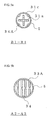
FIG. 5 shows a cross-sectional view of a prefilled syringe 1C of the third embodiment, where (a) is a view representing from arrow direction B1-B1 and (b) is a view representing from arrow direction A2-A2. -
FIG. 6 shows a prefilled syringe 1D of the second embodiment, where (a) is a plan view, (b) is a side cross-sectional view, and (c) is a side view. -
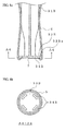
FIG. 7 shows a cross-sectional view of a prefilled syringe of the forth embodiment, where (a) is a view representing from arrow direction B2-B2 and (b) is a view representing from arrow direction A3-A3. -
FIG 8 shows a view representing a embodiment of being directly adhered a filter member to the disc-shaped flange, where (a) is a side cross-sectional view of a base of a plunger rod, and (b) is a view representing the above from arrow direction A4-A4. -
- 1A prefilled syringe (first embodiment)
- 1B prefilled syringe (second embodiment)
- 1C prefilled syringe (third embodiment)
- 1D prefilled syringe (forth embodiment)
- 2 syringe barrel
- 3 plunger
- 4 cap
- 5 shrink film
- 6 barrier packaging
- 7 filter member
- 10 drug
- 21 extension
- 24 second disc-shaped rib
- 31 plunger rod (plunger)
- 31 c first disc-shaped rib
- 32 gasket
- 33 disc-shaped flange
- 34 air through-hole
- The following is a detailed description of embodiments of a prefilled syringe of the present invention based on
FIG. 1 to FIG. 8 .
First, a description is given of a first embodiment of a prefilled syringe of the present invention usingFIG. 1 . A prefilled syringe 1A filled with a drug and covered in barrier packaging is shown inFIG. 1 , where (a) is a plan view, and (b) is a side cross-sectional view. - The prefilled syringe 1A is equipped with a
syringe barrel 2 filled with adrug 10 and aplunger 3. Theplunger 3 is equipped with aplunger rod 31 and agasket 32 provided at the tip of theplunger rod 31. Thesyringe barrel 2 is equipped with anozzle 20 capable of being fitted with an injection needle etc., and anopening 22 that theplunger 3 can freely move within. Further, agrip 23 is formed projecting from the periphery of the tip of theopening 22. As shown in the plan view, thegrip 23 is an ellipsoidal plate-shaped projection. This therefore gives a shape that is easy for a person to grip while the disc-shapedflange 33 formed at a base end of theplunger 3 is pushed in so that theplunger 3 moves within thesyringe barrel 2. - A
cap 4 is then fitted to the tip of thenozzle 20 and is sealed in a fluid-tight manner so that the filleddrug 10 does not leak out. It is also possible to cover the whole of the outer periphery of thecap 4 with theshrink film 5. In order to prevent thecap 4 inadvertently coming off or coming loose, from thecap 4 to the tip of thesyringe barrel 2 is covered in ashrink film 5. - Further, the outer surface of the
syringe barrel 2 filled with the drug is covered withbarrier packaging 6 so as to suppress deterioration of the drug. During this time, in order to reliably cover the entire outer surface of thesyringe barrel 2, a guard-shaped extension 21 is provided projecting from the outer periphery of a shoulder section of the syringe barrel on the side of thenozzle 20.
A range spanning from a part where thegasket 32 of the plunger with theplunger 3 fitted is positioned to a guard-shaped extension 21 is covered by thebarrier packaging 6. Covering from the base end of thegasket 32 is preferable. - Moreover, the
shrink film 5 covers up to the tip of thebarrier packaging 6. Gas barrier packaging with superior transparency such as enables filling with a drug to be confirmed and that provides a barrier to oxygen in order to prevent oxidation of the drug is preferable as thebarrier packaging 6.
Further, thebarrier packaging 6 simply covers the outer periphery of thecylindrical syringe barrel 2 and flexibility is not taken to be important. - The prefilled syringe 1A of the above structure is such that filled
drug 10 does not degrade or leak out and can therefore be taken out and kept one at a time. This contributes to an increase in operation efficiency when used at locations such as hospitals and to reduction of storage space.
Theshrink film 5 can cover not just the syringe tip that thecap 4 is installed at but can also cover the whole of the syringe including theplunger 3 in an integrated manner. A prefilled syringe 1B of this structure is described usingFIG. 2 . - The prefilled syringe 1B of a second embodiment is shown in
FIG. 2 , where (a) is a plan view and (b) is a side cross-sectional view, and (c) is a side view.
The prefilled syringe 1B having thesyringe barrel 2 filled with thedrug 10 and theplunger 3 having theplunger rod 31 and thegasket 32 is the same as described above for the prefilled syringe 1A.
Further, theshrink film 5 is made so as to cover the whole of the syringe including theplunger 3 in an integrated manner. As a result, not only is coming off and loosening of theplunger 3 prevented, but it is also made difficult for outside air to permeate to within thesyringe 2 and microbial contaminants also cannot permeate. This increases the degree of safety. - However, when a method using, for example, high-pressure steam sterilization is adopted at the time of thermally shrinking of the
shrink film 5, there is the fear that moisture of an air-tight space will condense and remain within the space. In this embodiment, the structure is such that a base end 31b of theplunger rod 31 is made in the shape of a duckboard, with afilter member 7 having moisture permeability so that moisture passes through but microbial contaminants do not interposed there between.
Making the base end 31b of theplunger rod 31 the shape of a duckboard is in order to ensure a communicating path moisture in the air-tight space can permeate through. As a result, in this embodiment, the surface is a structure (refer toFIG. 3 ) where air through-holes 34 are provided at recesses of an undulating surface of a disc-shaped flange 33A with a duckboard-shaped surface. This means that even if thefilter member 7 is adhered to the disc-shaped flange 33A, contacting takes place only with the convex parts of the disc-shaped flange 33A and not with the air through-holes 34. - This means that even if, for example, the air through-
holes 34 are small, thefilter member 7 is not attached directly and the spaces before and after the through-holes communicate with each other. A communicating path that moisture of the air-tight space can pass through can therefore be ensured.
Tyvek (registered trademark of Dupont) unwoven cloth sheets where continuous very fine fibers of polyethylene of, for example, 0.5 to 1 microns are subjected to high-temperatures so as to be bonded is preferably utilized as thefilter member 7. It is also possible to use other sterilized paper that is permeable to moisture.
Theplunger rod 31 constituting theplunger 3 may be formed by arranging a disc-shaped flange at a small-diameter rod. However, as in this embodiment, it is also possible to provide sleeves 31 a projecting in a radial direction at a plurality of locations in a circumferential direction of a center axis of a small diameter. With this configuration, large air-tight spaces are formed between neighboring sleeves 31 a when the entirety is covered by theshrink film 5. A structure is therefore adopted where thefilter member 7 for moisture sealed within the spaces to pass through is provided at the disc-shaped flange 33A of the plunger rod base. - Namely, as shown in
FIG. 3 , a structure is adopted where air through-holes 34 are provided at the disc-shaped flange 33A and thefilter member 7 that allows moisture to pass through but that does not allow microbial contaminants to pass is fitted at the outside. It is sufficient for the air through-holes 34 to be provided at at least one location at the disc-shaped flange 33A but if a structure where a plurality are provided is adopted, it is preferable for passing through of the moisture to take place rapidly.
In the above, a structure may be adopted that is covered on top by the shrink film 5 (refer toFIG. 8 ) as the structure for directly mounting thefilter member 7 at the disc-shaped flange 33A. However, adopting a structure where alid member 35 supporting thefilter member 7 is arranged at the outside of the disc-shaped flange 33A with the top then being covered by theshrink film 5 is preferable because selection and mounting of thefilter member 7 having predetermined functions is straightforward. The shape of thelid member 35 can also be arbitrarily selected compared to the disc-shaped flange and a shape where adhesion with the shrink film is superior can therefore be adopted.
In addition, it is also possible to provide an uneven surface or air through-holes at an outer peripheral edge of the disc-shaped flange 33A and the surface of the base or to enable theshrink film 5 to become wrinkled, in order to ensure a communicating path when theshrink film 5 is heat-shrank in advance in order to cover the outer edge of the disc-shaped flange 33A. The lid-shapedfilter member 7 that allows moisture to permeate but does not allow microbial contaminants to permeate can then be fitted at the disc-shaped flange 33A in such a manner as to include the boundary of the disc-shaped flange 33A and theshrink film 5. - Numeral 51 denotes a pull-tag for opening use. The
shrink film 5 can then be opened by holding the pull-tag 51 and tearing the pull-tag 51 in a strip shape.
Next, a description is given of a prefilled syringe 1C of a third embodiment provided with a plunger rod having disc-shaped ribs projecting in a radial direction usingFIG. 4 . - The prefilled syringe 1C of the third embodiment is shown in
FIG. 4 , where (a) is a plan view and (b) is a side cross-sectional view, and (c) is a side view.
The prefilled syringe 1C is equipped with thesyringe barrel 2 filled with thedrug 10 and a plunger 3A. Further, the plunger 3A has a plunger rod 31A and thegasket 32.
Theshrink film 5 covering the whole of the syringe including the plunger 3A in an integrated manner, providing the air through-holes 34 at the disc-shaped flange 33A, and fitting thefilter member 7 are the same as for the prefilled syringe 1B. However, the adopted configuration is such that a first disc-shaped rib 31c projecting in a radial direction is provided at a central part of the plunger rod 31A constituting the plunger 3A.
The disc-shaped rib 31 c is inserted within thesyringe barrel 2. Dimensions are therefore adopted where an outer diameter D2 of the disc-shaped rib 31 c is smaller than an inner diameter D1 of thesyringe barrel 2. - Because of this, an external diameter D3 of a sleeve part of the plunger rod 31A is given a smaller diameter and a stepped shape. The disc-shaped rib 31 c positioned at a central part of the
plunger rod 31 therefore has a projecting external shape when theshrink film 5 covers the whole of the syringe including the plunger 3A in an integrated manner.
If the above configuration is adopted, it is possible to suppress movement in an axial direction of the plunger 3A using theshrink film 5 attached firmly so as to be fixed to the projecting first disc-shaped rib 31c. Namely, the position of the plunger 3A is fixed and does not move even if pushed or pulled. It is therefore possible to reliably prevent the filleddrug 10 from leaking out.
The prefilled syringe 1C of this embodiment is capable of being transported and stored as is and outer packaging such as blister packaging is unnecessary. It is therefore possible to save on storage space. - By adopting the above configuration, when the pull-tag 51 for opening is gripped in a motionless manner prior to opening and a strip shape is torn so as to open the
shrink film 5, the plunger rod 31A can easily be pushed into thesyringe barrel 2.
As shown inFIG. 5(a) , first disc-shaped rib 31 c has a circular cross-section. When covered with theshrink film 5, this is reliably attached firmly to this circular outer shape and the inside is sealed to a high extent. - The air through-
holes 34 that are capable of allowing moisture enclosed in the space to pass through are provided at the first disc-shaped rib 31c. According to this structure, it is possible for moisture to escape via thefilter member 7 from the air through-holes 34A provided at the disc-shaped rib 31 c and the air through-holes 34 (refer toFIG. 5(b) ) provided at the disc-shaped flange 33A even if a structure provided with the first disc-shaped rib 31 c at this central part is adopted for the plunger rod 31A.
Next, a description is given of a prefilled syringe 1D of a fourth embodiment provided with a projecting disc-shaped rib in the vicinity of the base of the syringe barrel usingFIG. 6 . - The prefilled syringe 1D of the fourth embodiment is shown in
FIG. 6 , where (a) is a plan view, (b) is a side cross-sectional view, and (c) is a side view.
The prefilled syringe 1D is an example where, in addition to the prefilled syringe 1C described above, a second disc-shapedrib 24 is provided in the vicinity of the base close to thegrip 23 of thesyringe barrel 2. The basic structure relating to the syringe body is the same as for the prefilled syringe 1C and is not described here. It is also possible to provide a plurality of second disc-shapedribs 24. - If the prefilled syringe 1D of the above configuration is adopted, the
shrink film 5 is attached firmly so as to be fixed to the projecting second disc-shapedrib 24. It is therefore possible to reliably prevent microbial contaminants etc. from infiltrating from the nozzle tip thecap 4 is fitted to and a more desirable structure is achieved.
There is also the benefit that even if the pull-tag 51 for opening use is grasped and torn in a strip-shape so as to open theshrink film 5 with the syringe then being taken out, microbial contaminants do not become attached to thegrip 23 or the plunger rod 31A. There is therefore the further benefit that there is no fear of microbial contaminants infiltrating into the filleddrug 10. -
FIG. 7(a) is a cross-sectional view of the disc-shaped rib 31c, andFIG. 7(b) is a cross-sectional view of a disc-shapedflange 33. Both have a circular cross-section and are shown to have a plurality of air through-holes 34 and 34A.
Thefilter member 7 is set at the outer side of the disc-shaped flange 33A via thelid member 35. However, it is also possible for thefilter member 7 to be directly mounted at the disc-shaped flange 33A as described above and an example of this structure is described usingFIG. 8 . - An example where the
filter member 7 is directly mounted at the disc-shaped flange is shown inFIG. 8 , where (a) is a side cross-sectional view of the plunger rod base and (b) is a view along arrows A4-A4 of the previous drawing.
The plunger rod 31 B shown in the drawing is provided with a disc-shaped flange 33B having air through-holes 34B at its base, with thefilter member 7 being directly applied to the outer side of the disc-shaped flange 33B. - During this time, if a structure is adopted where a recess 33Ba is provided for fitting the
filter member 7 to the outer side of the disc-shaped flange 33B, it is preferable for thefilter member 7 to be reliably mounted at a normal position.
The shape of the air through-holes 34B is by no means particularly limited, and the air through-holes 34B can be a plurality of ellipsoidal holes as shown inFIG. 8(b) or can be circular holes. It is also preferable for the air through-holes to have a surface area of an order enabling moisture in the air-tight space formed by sealing during covering the whole inshrink film 5 to pass rapidly. - As described above, the
filter member 7 is a film that is permeable to moisture and suppresses the passage of microbial contaminants. This means that moisture does not remain and can be eliminated even when the syringe is covered entirely by theshrink film 5.
As a result, even if moisture remains within the sealed space, this moisture can be rapidly eliminated while shrinking theshrink film 5 that is heat-shrinkable resin film utilizing heat at the time of, for example, high-pressure steam sterilization. Further, microbial contaminants also do not permeate into the sterilized sealed space from outside. This means that it is possible to guarantee the sterility of the syringe right up to immediately before use and it is therefore possible to form syringe containing packaging where permeation of microbial contaminants into the syringe can be prevented to a high extent. - As described above, according to the prefilled syringe of the present invention, it is possible to reliably prevent degradation of a drug filled in advance. Further, keeping of single packed syringes is possible, handling is straightforward, and storage space savings can be made.
Further, it is possible to prevent permeation of microbial contaminants into a sterilized sealed space from outside to a high extent. This means that use with peace of mind is possible and that a prefilled syringe with superior ease of use can be obtained. - Moreover, it is also possible for the present invention to give the shrink film color in order to block light under the assumption that there will be cases such as the syringe barrel element being in the light while being kept so that radicals are formed and degradation due to oxidation takes place, the case of elution in medicinal solution, or in the case that a medicinal solution has photodegradative properties.
Claims (9)
- A prefilled syringe (1A, 1B, 1C, 1D) filled in advance with a drug (10) within a syringe barrel (2) which comprises a nozzle (20) fitted with an injection needle, and an opening (22) where a plunger (3), equipped with a gasket (32) at an end of a plunger rod (31), freely moves backwards and forwards,
wherein the prefilled syringe (1A,1B,1C,1D) has a guard-shaped extension (21) projecting from the outer periphery of a shoulder section of the syringe barrel (2) on the nozzle (20) side, and
a range from a part, where a gasket (32) of the plunger (3) is positioned, on the outer surface of the syringe barrel (2) filled with the drug (10) to the guard-shaped extension (21) is covered with a barrier packaging (6). - The prefilled syringe (1A,1B,1C,1D) according to claim 1, wherein a cap (4) is fitted to the end of the nozzle (20), and the entire outer peripheral surface from the cap (4) to the end of the extension (21) is covered by a shrink film (5).
- The prefilled syringe (1A,1B,1C,1D) according to claim 1, wherein a cap (4) is fitted to the end of the nozzle (20), and the whole of the outer peripheral surface of the syringe (1A,1B,1C,1D) of a structure where the cap (4) and the plunger (3) are fitted is covered with a shrink film (5).
- The prefilled syringe (1A,1B,1C,1D) according to claim 3, wherein an air through-hole (34) is provided at a disc-shaped flange (33) arranged at a base of the plunger rod (31), during covering of the whole syringe using the shrink film (5), the outer surface of the disc-shaped flange (33) is exposed, a filter member (7) that is permeable to moisture is arranged at the outer surface side of the exposed disc-shaped flange (33) so as to cover the air through-hole (34).
- The prefilled syringe (1A,1B,1C,1D) according to claim 4, wherein the surface of the disc-shaped flange (33) is taken to be a duckboard-shaped uneven surface, with the air through-hole (34) provided at a recess.
- The prefilled syringe (1A,1B,1C,1D) according to claim 4 or 5, wherein at least one first disc-shaped rib (31 c) is provided projecting from a central part of the plunger rod (31), air through-hole (34) is provided at the disc-shaped rib (31 c), and an outer diameter of the disc-shaped rib (31 c) is of an order enabling passing through at the opening.
- The prefilled syringe (1A,1B,1C,1D) according to any one of claims 4 to 6, wherein at least one second disc-shaped rib (24) is provided in a projecting manner in the vicinity of the base of the syringe barrel (2).
- The prefilled syringe (1A,1B,1C,1D) according to any one of claims 4 to 7, wherein a lid member having the filter member (7) is fitted at the disc-shaped flange (33).
- The prefilled syringe (1A,1B,1C,1D) according to claim 7 or 8, wherein the shrink film (5) is attached firmly to the first disc-shaped rib (31 c) and the second disc-shaped rib (24) so that the whole of the syringe is covered, and the shrink film (5) is heat-shrank by heating during high-pressure sterilization.
Applications Claiming Priority (3)
| Application Number | Priority Date | Filing Date | Title |
|---|---|---|---|
| JP2005240137 | 2005-08-22 | ||
| JP2005325835 | 2005-11-10 | ||
| PCT/JP2006/316231 WO2007023736A1 (en) | 2005-08-22 | 2006-08-18 | Prefilled syringe |
Publications (3)
| Publication Number | Publication Date |
|---|---|
| EP1930040A1 true EP1930040A1 (en) | 2008-06-11 |
| EP1930040A4 EP1930040A4 (en) | 2009-12-02 |
| EP1930040B1 EP1930040B1 (en) | 2011-03-16 |
Family
ID=37771484
Family Applications (1)
| Application Number | Title | Priority Date | Filing Date |
|---|---|---|---|
| EP06796542A Active EP1930040B1 (en) | 2005-08-22 | 2006-08-18 | Prefilled syringe |
Country Status (6)
| Country | Link |
|---|---|
| US (1) | US8043267B2 (en) |
| EP (1) | EP1930040B1 (en) |
| JP (1) | JP4941303B2 (en) |
| CN (1) | CN101247843B (en) |
| DE (1) | DE602006020744D1 (en) |
| WO (1) | WO2007023736A1 (en) |
Cited By (2)
| Publication number | Priority date | Publication date | Assignee | Title |
|---|---|---|---|---|
| WO2013176703A1 (en) * | 2012-05-21 | 2013-11-28 | Baxter International, Inc. | Syringe storage tray |
| WO2013184270A1 (en) * | 2012-05-07 | 2013-12-12 | Centurion Medical Products Corporation | Prefilled container systems |
Families Citing this family (16)
| Publication number | Priority date | Publication date | Assignee | Title |
|---|---|---|---|---|
| US9592375B2 (en) | 2006-05-18 | 2017-03-14 | Hyprotek, Inc. | Intravascular line and port cleaning methods, methods of administering an agent intravascularly, methods of obtaining/testing blood, and devices for performing such methods |
| JP2009240411A (en) * | 2008-03-28 | 2009-10-22 | Terumo Corp | Drug container |
| JP5618440B2 (en) * | 2008-08-25 | 2014-11-05 | 電気化学工業株式会社 | Syringe |
| US8337473B2 (en) * | 2010-07-16 | 2012-12-25 | Christian Javier Zino Gutierrez | Substance dispenser, especially for medical or cosmetic treatment |
| US9572922B2 (en) | 2012-12-21 | 2017-02-21 | Larry Leonard | Inventive diabetic systems, tools, kits, and supplies for better diabetic living and mobility |
| SG11201405136PA (en) * | 2012-02-29 | 2014-11-27 | Hyprotek Inc | Intravascular line and port cleaning methods, methods of administering an agent intravascularly, methods of obtaining/testing blood, and devices for performing such methods |
| US9265889B2 (en) | 2012-04-25 | 2016-02-23 | Adar Medtech, Inc. | Prefilled medical injection device |
| US10064990B2 (en) * | 2012-07-16 | 2018-09-04 | Becton, Dickinson And Company | Packageless syringe assembly with sterilizable fluid path |
| ES2695158T3 (en) | 2013-03-14 | 2019-01-02 | Fresenius Kabi Deutschland Gmbh | Packaging system for oxygen-sensitive drugs |
| WO2014140095A1 (en) | 2013-03-14 | 2014-09-18 | Becton Dickinson France S.A.S. | Injectable morphine formulations |
| WO2015147305A1 (en) * | 2014-03-28 | 2015-10-01 | テルモ株式会社 | Packaged drug-filled container |
| EP3319658B1 (en) | 2015-07-10 | 2021-01-13 | Fresenius Kabi Austria GmbH | Syringe packaging system |
| US10814059B2 (en) * | 2015-07-10 | 2020-10-27 | Fresenius Kabi Deutschland Gmbh | Syringe packaging system |
| CN113840589A (en) * | 2019-05-17 | 2021-12-24 | 西医药服务有限公司 | Adaptive primary packaging for therapeutic solutions |
| US20220323740A1 (en) * | 2021-04-07 | 2022-10-13 | Carefusion 303, Inc. | Protective membrane for medical luer connectors |
| WO2024182591A1 (en) | 2023-03-01 | 2024-09-06 | Pacto Medical Inc. | Assemblable compact syringe with side mounted plunger rod |
Family Cites Families (18)
| Publication number | Priority date | Publication date | Assignee | Title |
|---|---|---|---|---|
| US3149717A (en) | 1962-08-27 | 1964-09-22 | Johnson & Johnson | Container for hypodermic needle |
| DE1486484A1 (en) | 1965-06-24 | 1969-06-04 | Linder Dr Fritz | Bacteria-proof, sealable plastic bag to hold items to be sterilized |
| US3503497A (en) * | 1968-07-25 | 1970-03-31 | Pall Corp | Breather container |
| ATE39325T1 (en) | 1984-11-02 | 1989-01-15 | Duphar Int Res | AUTOMATIC INJECTION DEVICE. |
| US5147309A (en) | 1991-10-22 | 1992-09-15 | Biosafety Systems, Inc. | Apparatus for priming a hypodermic needle with hazardous fluid |
| US5238003A (en) * | 1992-02-07 | 1993-08-24 | Baidwan Balinderjeet S | Plunger tip for blood gas syringe |
| WO1994020161A1 (en) * | 1993-03-02 | 1994-09-15 | Seikagaku Kogyo Kabushiki Kaisha | Drug-containing syringe |
| US5498244A (en) * | 1993-09-22 | 1996-03-12 | American Home Products Corporation | Safety guard for medical instruments |
| JPH07289639A (en) | 1994-04-27 | 1995-11-07 | Fuji Seal Co Ltd | Medicinal fluid-containing injector |
| JPH11332984A (en) | 1998-05-26 | 1999-12-07 | Terumo Corp | Medicinal liquid-containing syringe |
| US6183464B1 (en) * | 1998-06-01 | 2001-02-06 | Inviro Medical Devices Ltd. | Safety syringe with retractable needle and universal luer coupling |
| FR2781682B1 (en) * | 1998-07-29 | 2000-09-15 | Aguettant Lab | INVIOLABILITY DEVICE OF A PREFILLED SYRINGE |
| JP2001029466A (en) | 1999-07-15 | 2001-02-06 | Hiroshi Motobayashi | Prefilled syringe |
| JP2001112867A (en) * | 1999-10-18 | 2001-04-24 | Terumo Corp | Syringe containing drug |
| JP4567274B2 (en) | 2001-01-29 | 2010-10-20 | 中外製薬株式会社 | Manufacturing method of prefilled small syringe |
| US7081107B2 (en) * | 2002-07-02 | 2006-07-25 | Terumo Kabushiki Kaisha | Syringe and prefilled syringe |
| JP2004229750A (en) * | 2003-01-28 | 2004-08-19 | Nipro Corp | Method for manufacturing prefilled syringe and barrel thereof |
| JP2004267662A (en) | 2003-03-12 | 2004-09-30 | Toppan Printing Co Ltd | Prefilled syringe |
-
2006
- 2006-08-18 CN CN2006800306148A patent/CN101247843B/en not_active Expired - Fee Related
- 2006-08-18 US US12/063,828 patent/US8043267B2/en not_active Expired - Fee Related
- 2006-08-18 JP JP2007532086A patent/JP4941303B2/en not_active Expired - Fee Related
- 2006-08-18 WO PCT/JP2006/316231 patent/WO2007023736A1/en not_active Ceased
- 2006-08-18 EP EP06796542A patent/EP1930040B1/en active Active
- 2006-08-18 DE DE602006020744T patent/DE602006020744D1/en active Active
Cited By (7)
| Publication number | Priority date | Publication date | Assignee | Title |
|---|---|---|---|---|
| WO2013184270A1 (en) * | 2012-05-07 | 2013-12-12 | Centurion Medical Products Corporation | Prefilled container systems |
| US10780228B2 (en) | 2012-05-07 | 2020-09-22 | Medline Industries, Inc. | Prefilled container systems |
| EP4218854A3 (en) * | 2012-05-07 | 2023-08-09 | Medline Industries, LP | Prefilled container systems |
| US11786664B2 (en) | 2012-05-07 | 2023-10-17 | Medline Industries, Lp | Prefilled container systems |
| WO2013176703A1 (en) * | 2012-05-21 | 2013-11-28 | Baxter International, Inc. | Syringe storage tray |
| US9808570B2 (en) | 2012-05-21 | 2017-11-07 | Baxalta Incorporated | Syringe storage tray |
| US9889248B2 (en) | 2012-05-21 | 2018-02-13 | Baxalta GmbH | Syringe storage tray |
Also Published As
| Publication number | Publication date |
|---|---|
| EP1930040A4 (en) | 2009-12-02 |
| JP4941303B2 (en) | 2012-05-30 |
| JPWO2007023736A1 (en) | 2009-02-26 |
| WO2007023736A1 (en) | 2007-03-01 |
| US8043267B2 (en) | 2011-10-25 |
| CN101247843B (en) | 2010-09-29 |
| EP1930040B1 (en) | 2011-03-16 |
| CN101247843A (en) | 2008-08-20 |
| US20090281504A1 (en) | 2009-11-12 |
| DE602006020744D1 (en) | 2011-04-28 |
Similar Documents
| Publication | Publication Date | Title |
|---|---|---|
| EP1930040B1 (en) | Prefilled syringe | |
| JP4570696B2 (en) | Gas syringe device | |
| KR100460000B1 (en) | Seal Protector for Syringes | |
| US10507280B2 (en) | Medical instrument housing container | |
| JP6072758B2 (en) | Medical device package and method for producing medical device package | |
| EP1285672B1 (en) | Prefilled injector package and sterilizing or disinfecting method therefor. | |
| US10729843B2 (en) | Dual packaging for fill needle and safety needle | |
| US20180161491A1 (en) | Packaging For Safety Needle | |
| JP2018114311A (en) | Filled container system | |
| JP2012071046A (en) | Outer cylinder package for prefilled syringe and container body for outer cylinder package for prefilled syringe | |
| US11173253B2 (en) | Packaging for safety needle | |
| FR2911072A1 (en) | PACKAGING FOR PRODUCTS WHICH MUST BE DECONTAMINATED BY RADIATION | |
| JPH0857046A (en) | Packaged syringe assembly and method of manufacturing the same | |
| JP7717084B2 (en) | safety needle packaging | |
| KR100390266B1 (en) | wrapping method of disposable syringe and the wrapped syringe | |
| JP4826203B2 (en) | Packaging structure for local anesthetics | |
| JPH08238314A (en) | Injection syringe | |
| JPH08332224A (en) | Syringe |
Legal Events
| Date | Code | Title | Description |
|---|---|---|---|
| PUAI | Public reference made under article 153(3) epc to a published international application that has entered the european phase |
Free format text: ORIGINAL CODE: 0009012 |
|
| 17P | Request for examination filed |
Effective date: 20080319 |
|
| AK | Designated contracting states |
Kind code of ref document: A1 Designated state(s): AT BE BG CH CY CZ DE DK EE ES FI FR GB GR HU IE IS IT LI LT LU LV MC NL PL PT RO SE SI SK TR |
|
| A4 | Supplementary search report drawn up and despatched |
Effective date: 20091104 |
|
| 17Q | First examination report despatched |
Effective date: 20100201 |
|
| GRAP | Despatch of communication of intention to grant a patent |
Free format text: ORIGINAL CODE: EPIDOSNIGR1 |
|
| RIC1 | Information provided on ipc code assigned before grant |
Ipc: A61M 5/00 20060101ALI20100910BHEP Ipc: A61M 5/28 20060101AFI20100910BHEP |
|
| DAX | Request for extension of the european patent (deleted) | ||
| GRAS | Grant fee paid |
Free format text: ORIGINAL CODE: EPIDOSNIGR3 |
|
| GRAA | (expected) grant |
Free format text: ORIGINAL CODE: 0009210 |
|
| AK | Designated contracting states |
Kind code of ref document: B1 Designated state(s): AT BE BG CH CY CZ DE DK EE ES FI FR GB GR HU IE IS IT LI LT LU LV MC NL PL PT RO SE SI SK TR |
|
| REG | Reference to a national code |
Ref country code: GB Ref legal event code: FG4D |
|
| REG | Reference to a national code |
Ref country code: CH Ref legal event code: EP |
|
| REG | Reference to a national code |
Ref country code: IE Ref legal event code: FG4D |
|
| REF | Corresponds to: |
Ref document number: 602006020744 Country of ref document: DE Date of ref document: 20110428 Kind code of ref document: P |
|
| REG | Reference to a national code |
Ref country code: DE Ref legal event code: R096 Ref document number: 602006020744 Country of ref document: DE Effective date: 20110428 |
|
| REG | Reference to a national code |
Ref country code: CH Ref legal event code: NV Representative=s name: BOHEST AG |
|
| REG | Reference to a national code |
Ref country code: NL Ref legal event code: VDEP Effective date: 20110316 |
|
| PG25 | Lapsed in a contracting state [announced via postgrant information from national office to epo] |
Ref country code: SE Free format text: LAPSE BECAUSE OF FAILURE TO SUBMIT A TRANSLATION OF THE DESCRIPTION OR TO PAY THE FEE WITHIN THE PRESCRIBED TIME-LIMIT Effective date: 20110316 Ref country code: ES Free format text: LAPSE BECAUSE OF FAILURE TO SUBMIT A TRANSLATION OF THE DESCRIPTION OR TO PAY THE FEE WITHIN THE PRESCRIBED TIME-LIMIT Effective date: 20110627 Ref country code: LT Free format text: LAPSE BECAUSE OF FAILURE TO SUBMIT A TRANSLATION OF THE DESCRIPTION OR TO PAY THE FEE WITHIN THE PRESCRIBED TIME-LIMIT Effective date: 20110316 Ref country code: LV Free format text: LAPSE BECAUSE OF FAILURE TO SUBMIT A TRANSLATION OF THE DESCRIPTION OR TO PAY THE FEE WITHIN THE PRESCRIBED TIME-LIMIT Effective date: 20110316 Ref country code: GR Free format text: LAPSE BECAUSE OF FAILURE TO SUBMIT A TRANSLATION OF THE DESCRIPTION OR TO PAY THE FEE WITHIN THE PRESCRIBED TIME-LIMIT Effective date: 20110617 |
|
| LTIE | Lt: invalidation of european patent or patent extension |
Effective date: 20110316 |
|
| PG25 | Lapsed in a contracting state [announced via postgrant information from national office to epo] |
Ref country code: AT Free format text: LAPSE BECAUSE OF FAILURE TO SUBMIT A TRANSLATION OF THE DESCRIPTION OR TO PAY THE FEE WITHIN THE PRESCRIBED TIME-LIMIT Effective date: 20110316 Ref country code: FI Free format text: LAPSE BECAUSE OF FAILURE TO SUBMIT A TRANSLATION OF THE DESCRIPTION OR TO PAY THE FEE WITHIN THE PRESCRIBED TIME-LIMIT Effective date: 20110316 Ref country code: BG Free format text: LAPSE BECAUSE OF FAILURE TO SUBMIT A TRANSLATION OF THE DESCRIPTION OR TO PAY THE FEE WITHIN THE PRESCRIBED TIME-LIMIT Effective date: 20110616 Ref country code: CY Free format text: LAPSE BECAUSE OF FAILURE TO SUBMIT A TRANSLATION OF THE DESCRIPTION OR TO PAY THE FEE WITHIN THE PRESCRIBED TIME-LIMIT Effective date: 20110316 Ref country code: SI Free format text: LAPSE BECAUSE OF FAILURE TO SUBMIT A TRANSLATION OF THE DESCRIPTION OR TO PAY THE FEE WITHIN THE PRESCRIBED TIME-LIMIT Effective date: 20110316 |
|
| PG25 | Lapsed in a contracting state [announced via postgrant information from national office to epo] |
Ref country code: BE Free format text: LAPSE BECAUSE OF FAILURE TO SUBMIT A TRANSLATION OF THE DESCRIPTION OR TO PAY THE FEE WITHIN THE PRESCRIBED TIME-LIMIT Effective date: 20110316 |
|
| PG25 | Lapsed in a contracting state [announced via postgrant information from national office to epo] |
Ref country code: PT Free format text: LAPSE BECAUSE OF FAILURE TO SUBMIT A TRANSLATION OF THE DESCRIPTION OR TO PAY THE FEE WITHIN THE PRESCRIBED TIME-LIMIT Effective date: 20110718 Ref country code: EE Free format text: LAPSE BECAUSE OF FAILURE TO SUBMIT A TRANSLATION OF THE DESCRIPTION OR TO PAY THE FEE WITHIN THE PRESCRIBED TIME-LIMIT Effective date: 20110316 |
|
| PG25 | Lapsed in a contracting state [announced via postgrant information from national office to epo] |
Ref country code: RO Free format text: LAPSE BECAUSE OF FAILURE TO SUBMIT A TRANSLATION OF THE DESCRIPTION OR TO PAY THE FEE WITHIN THE PRESCRIBED TIME-LIMIT Effective date: 20110316 Ref country code: SK Free format text: LAPSE BECAUSE OF FAILURE TO SUBMIT A TRANSLATION OF THE DESCRIPTION OR TO PAY THE FEE WITHIN THE PRESCRIBED TIME-LIMIT Effective date: 20110316 Ref country code: IS Free format text: LAPSE BECAUSE OF FAILURE TO SUBMIT A TRANSLATION OF THE DESCRIPTION OR TO PAY THE FEE WITHIN THE PRESCRIBED TIME-LIMIT Effective date: 20110716 Ref country code: CZ Free format text: LAPSE BECAUSE OF FAILURE TO SUBMIT A TRANSLATION OF THE DESCRIPTION OR TO PAY THE FEE WITHIN THE PRESCRIBED TIME-LIMIT Effective date: 20110316 |
|
| PG25 | Lapsed in a contracting state [announced via postgrant information from national office to epo] |
Ref country code: NL Free format text: LAPSE BECAUSE OF FAILURE TO SUBMIT A TRANSLATION OF THE DESCRIPTION OR TO PAY THE FEE WITHIN THE PRESCRIBED TIME-LIMIT Effective date: 20110316 |
|
| PLBE | No opposition filed within time limit |
Free format text: ORIGINAL CODE: 0009261 |
|
| STAA | Information on the status of an ep patent application or granted ep patent |
Free format text: STATUS: NO OPPOSITION FILED WITHIN TIME LIMIT |
|
| 26N | No opposition filed |
Effective date: 20111219 |
|
| PG25 | Lapsed in a contracting state [announced via postgrant information from national office to epo] |
Ref country code: PL Free format text: LAPSE BECAUSE OF FAILURE TO SUBMIT A TRANSLATION OF THE DESCRIPTION OR TO PAY THE FEE WITHIN THE PRESCRIBED TIME-LIMIT Effective date: 20110316 Ref country code: DK Free format text: LAPSE BECAUSE OF FAILURE TO SUBMIT A TRANSLATION OF THE DESCRIPTION OR TO PAY THE FEE WITHIN THE PRESCRIBED TIME-LIMIT Effective date: 20110316 |
|
| PG25 | Lapsed in a contracting state [announced via postgrant information from national office to epo] |
Ref country code: MC Free format text: LAPSE BECAUSE OF NON-PAYMENT OF DUE FEES Effective date: 20110831 |
|
| REG | Reference to a national code |
Ref country code: DE Ref legal event code: R097 Ref document number: 602006020744 Country of ref document: DE Effective date: 20111219 |
|
| REG | Reference to a national code |
Ref country code: FR Ref legal event code: ST Effective date: 20120430 |
|
| REG | Reference to a national code |
Ref country code: IE Ref legal event code: MM4A |
|
| PG25 | Lapsed in a contracting state [announced via postgrant information from national office to epo] |
Ref country code: IE Free format text: LAPSE BECAUSE OF NON-PAYMENT OF DUE FEES Effective date: 20110818 |
|
| PG25 | Lapsed in a contracting state [announced via postgrant information from national office to epo] |
Ref country code: FR Free format text: LAPSE BECAUSE OF NON-PAYMENT OF DUE FEES Effective date: 20110831 |
|
| PG25 | Lapsed in a contracting state [announced via postgrant information from national office to epo] |
Ref country code: LU Free format text: LAPSE BECAUSE OF NON-PAYMENT OF DUE FEES Effective date: 20110818 |
|
| PG25 | Lapsed in a contracting state [announced via postgrant information from national office to epo] |
Ref country code: TR Free format text: LAPSE BECAUSE OF FAILURE TO SUBMIT A TRANSLATION OF THE DESCRIPTION OR TO PAY THE FEE WITHIN THE PRESCRIBED TIME-LIMIT Effective date: 20110316 |
|
| PG25 | Lapsed in a contracting state [announced via postgrant information from national office to epo] |
Ref country code: HU Free format text: LAPSE BECAUSE OF FAILURE TO SUBMIT A TRANSLATION OF THE DESCRIPTION OR TO PAY THE FEE WITHIN THE PRESCRIBED TIME-LIMIT Effective date: 20110316 |
|
| REG | Reference to a national code |
Ref country code: CH Ref legal event code: PCAR Free format text: NEW ADDRESS: HOLBEINSTRASSE 36-38, 4051 BASEL (CH) |
|
| PGFP | Annual fee paid to national office [announced via postgrant information from national office to epo] |
Ref country code: IT Payment date: 20220825 Year of fee payment: 17 Ref country code: GB Payment date: 20220822 Year of fee payment: 17 Ref country code: DE Payment date: 20220620 Year of fee payment: 17 |
|
| PGFP | Annual fee paid to national office [announced via postgrant information from national office to epo] |
Ref country code: CH Payment date: 20220824 Year of fee payment: 17 |
|
| REG | Reference to a national code |
Ref country code: DE Ref legal event code: R119 Ref document number: 602006020744 Country of ref document: DE |
|
| REG | Reference to a national code |
Ref country code: CH Ref legal event code: PL |
|
| GBPC | Gb: european patent ceased through non-payment of renewal fee |
Effective date: 20230818 |
|
| PG25 | Lapsed in a contracting state [announced via postgrant information from national office to epo] |
Ref country code: CH Free format text: LAPSE BECAUSE OF NON-PAYMENT OF DUE FEES Effective date: 20230831 |
|
| PG25 | Lapsed in a contracting state [announced via postgrant information from national office to epo] |
Ref country code: GB Free format text: LAPSE BECAUSE OF NON-PAYMENT OF DUE FEES Effective date: 20230818 |
|
| PG25 | Lapsed in a contracting state [announced via postgrant information from national office to epo] |
Ref country code: IT Free format text: LAPSE BECAUSE OF NON-PAYMENT OF DUE FEES Effective date: 20230818 Ref country code: GB Free format text: LAPSE BECAUSE OF NON-PAYMENT OF DUE FEES Effective date: 20230818 Ref country code: DE Free format text: LAPSE BECAUSE OF NON-PAYMENT OF DUE FEES Effective date: 20240301 |