EP1928759B1 - Tubular membrane vent - Google Patents
Tubular membrane vent Download PDFInfo
- Publication number
- EP1928759B1 EP1928759B1 EP06801714A EP06801714A EP1928759B1 EP 1928759 B1 EP1928759 B1 EP 1928759B1 EP 06801714 A EP06801714 A EP 06801714A EP 06801714 A EP06801714 A EP 06801714A EP 1928759 B1 EP1928759 B1 EP 1928759B1
- Authority
- EP
- European Patent Office
- Prior art keywords
- membrane
- vent
- tubular
- tubular membrane
- fitting
- Prior art date
- Legal status (The legal status is an assumption and is not a legal conclusion. Google has not performed a legal analysis and makes no representation as to the accuracy of the status listed.)
- Not-in-force
Links
- 239000012528 membrane Substances 0.000 title claims description 106
- 239000000463 material Substances 0.000 claims description 11
- -1 polypropylene Polymers 0.000 claims description 7
- 229920001343 polytetrafluoroethylene Polymers 0.000 claims description 7
- 239000004810 polytetrafluoroethylene Substances 0.000 claims description 7
- 239000004677 Nylon Substances 0.000 claims description 5
- 229920001778 nylon Polymers 0.000 claims description 5
- 239000004743 Polypropylene Substances 0.000 claims description 4
- 229920001971 elastomer Polymers 0.000 claims description 4
- 230000002209 hydrophobic effect Effects 0.000 claims description 4
- 229920001155 polypropylene Polymers 0.000 claims description 4
- 238000005260 corrosion Methods 0.000 claims description 3
- 230000007797 corrosion Effects 0.000 claims description 3
- 239000002184 metal Substances 0.000 claims description 3
- 229910001220 stainless steel Inorganic materials 0.000 claims description 3
- 239000010935 stainless steel Substances 0.000 claims description 3
- DHKHKXVYLBGOIT-UHFFFAOYSA-N 1,1-Diethoxyethane Chemical compound CCOC(C)OCC DHKHKXVYLBGOIT-UHFFFAOYSA-N 0.000 claims description 2
- 229920004943 Delrin® Polymers 0.000 claims description 2
- 239000004809 Teflon Substances 0.000 claims description 2
- 229920006362 Teflon® Polymers 0.000 claims description 2
- 239000000806 elastomer Substances 0.000 claims description 2
- 239000004033 plastic Substances 0.000 claims description 2
- 229920003023 plastic Polymers 0.000 claims description 2
- 239000005060 rubber Substances 0.000 claims description 2
- 239000011354 acetal resin Substances 0.000 claims 1
- 239000004020 conductor Substances 0.000 claims 1
- 229920006324 polyoxymethylene Polymers 0.000 claims 1
- 125000002777 acetyl group Chemical class [H]C([H])([H])C(*)=O 0.000 description 1
- 239000000853 adhesive Substances 0.000 description 1
- 230000001070 adhesive effect Effects 0.000 description 1
- 238000011109 contamination Methods 0.000 description 1
- 230000001627 detrimental effect Effects 0.000 description 1
- 239000000428 dust Substances 0.000 description 1
- 229920006351 engineering plastic Polymers 0.000 description 1
- 239000004744 fabric Substances 0.000 description 1
- 238000003780 insertion Methods 0.000 description 1
- 230000037431 insertion Effects 0.000 description 1
- 239000007788 liquid Substances 0.000 description 1
- 239000000203 mixture Substances 0.000 description 1
- 239000012811 non-conductive material Substances 0.000 description 1
- 229910052755 nonmetal Inorganic materials 0.000 description 1
- 229920001296 polysiloxane Polymers 0.000 description 1
- 229920002635 polyurethane Polymers 0.000 description 1
- 239000004814 polyurethane Substances 0.000 description 1
- 238000007789 sealing Methods 0.000 description 1
- BFKJFAAPBSQJPD-UHFFFAOYSA-N tetrafluoroethene Chemical compound FC(F)=C(F)F BFKJFAAPBSQJPD-UHFFFAOYSA-N 0.000 description 1
- 238000009423 ventilation Methods 0.000 description 1
- XLYOFNOQVPJJNP-UHFFFAOYSA-N water Substances O XLYOFNOQVPJJNP-UHFFFAOYSA-N 0.000 description 1
Images



Classifications
-
- H—ELECTRICITY
- H05—ELECTRIC TECHNIQUES NOT OTHERWISE PROVIDED FOR
- H05K—PRINTED CIRCUITS; CASINGS OR CONSTRUCTIONAL DETAILS OF ELECTRIC APPARATUS; MANUFACTURE OF ASSEMBLAGES OF ELECTRICAL COMPONENTS
- H05K5/00—Casings, cabinets or drawers for electric apparatus
- H05K5/06—Hermetically-sealed casings
- H05K5/068—Hermetically-sealed casings having a pressure compensation device, e.g. membrane
-
- B—PERFORMING OPERATIONS; TRANSPORTING
- B01—PHYSICAL OR CHEMICAL PROCESSES OR APPARATUS IN GENERAL
- B01D—SEPARATION
- B01D53/00—Separation of gases or vapours; Recovering vapours of volatile solvents from gases; Chemical or biological purification of waste gases, e.g. engine exhaust gases, smoke, fumes, flue gases, aerosols
- B01D53/22—Separation of gases or vapours; Recovering vapours of volatile solvents from gases; Chemical or biological purification of waste gases, e.g. engine exhaust gases, smoke, fumes, flue gases, aerosols by diffusion
-
- B—PERFORMING OPERATIONS; TRANSPORTING
- B01—PHYSICAL OR CHEMICAL PROCESSES OR APPARATUS IN GENERAL
- B01D—SEPARATION
- B01D63/00—Apparatus in general for separation processes using semi-permeable membranes
- B01D63/06—Tubular membrane modules
-
- B—PERFORMING OPERATIONS; TRANSPORTING
- B01—PHYSICAL OR CHEMICAL PROCESSES OR APPARATUS IN GENERAL
- B01D—SEPARATION
- B01D65/00—Accessories or auxiliary operations, in general, for separation processes or apparatus using semi-permeable membranes
-
- B—PERFORMING OPERATIONS; TRANSPORTING
- B01—PHYSICAL OR CHEMICAL PROCESSES OR APPARATUS IN GENERAL
- B01D—SEPARATION
- B01D69/00—Semi-permeable membranes for separation processes or apparatus characterised by their form, structure or properties; Manufacturing processes specially adapted therefor
- B01D69/10—Supported membranes; Membrane supports
- B01D69/107—Organic support material
-
- B—PERFORMING OPERATIONS; TRANSPORTING
- B01—PHYSICAL OR CHEMICAL PROCESSES OR APPARATUS IN GENERAL
- B01D—SEPARATION
- B01D69/00—Semi-permeable membranes for separation processes or apparatus characterised by their form, structure or properties; Manufacturing processes specially adapted therefor
- B01D69/10—Supported membranes; Membrane supports
- B01D69/108—Inorganic support material
-
- H—ELECTRICITY
- H05—ELECTRIC TECHNIQUES NOT OTHERWISE PROVIDED FOR
- H05K—PRINTED CIRCUITS; CASINGS OR CONSTRUCTIONAL DETAILS OF ELECTRIC APPARATUS; MANUFACTURE OF ASSEMBLAGES OF ELECTRICAL COMPONENTS
- H05K5/00—Casings, cabinets or drawers for electric apparatus
- H05K5/02—Details
- H05K5/0213—Venting apertures; Constructional details thereof
-
- H—ELECTRICITY
- H05—ELECTRIC TECHNIQUES NOT OTHERWISE PROVIDED FOR
- H05K—PRINTED CIRCUITS; CASINGS OR CONSTRUCTIONAL DETAILS OF ELECTRIC APPARATUS; MANUFACTURE OF ASSEMBLAGES OF ELECTRICAL COMPONENTS
- H05K5/00—Casings, cabinets or drawers for electric apparatus
- H05K5/02—Details
- H05K5/0213—Venting apertures; Constructional details thereof
- H05K5/0216—Venting plugs comprising semi-permeable membranes
-
- B—PERFORMING OPERATIONS; TRANSPORTING
- B01—PHYSICAL OR CHEMICAL PROCESSES OR APPARATUS IN GENERAL
- B01D—SEPARATION
- B01D2313/00—Details relating to membrane modules or apparatus
- B01D2313/16—Specific vents
Definitions
- the present invention relates to ventilation of enclosures.
- Membrane vents are used, for example, in the automotive and telecommunications industries to equalize pressure between the interior and exterior of otherwise sealed enclosures.
- membranes In membrane vents, membranes generally comprise porous air-transmitting material that is preferably impermeable to liquids. Membrane vents are therefore able to equalize pressure, while minimizing contamination of enclosure interiors.
- a membrane vent at pressure equalization is dependant upon both the material composition of the membrane, and upon the membrane's surface area.
- a membrane is approximately flat and arranged perpendicular to, a small bore in the enclosure wall so as to completely cover the bore. This provides for a membrane surface area equal to or only slightly larger than the cross section of the bore, limiting the rate of pressure equalization. During, periods of moderate to high changes in interior or exterior pressure, such limited rates of pressure equalization proves detrimental.
- US 3868325 describes a fitting for a tubular filter on a tubular support. It would be desirable to improve the sealing properties of such a fitting.
- the present invention provides a membrane vent according to claim 1.
- a membrane vent is provided.
- the vent includes an air permeable tubular membrane, a tubular structural support adapted to be received by the tubular membrane, an air vent fitting attached to the tubular membrane at a first end and an end cap attached to the tubular membrane at a second end.
- the enclosure includes a membrane vent adapted to mount through a wall of the enclosure, the membrane vent comprising a tubular membrane, a tubular structural support, wherein the tubular membrane is stretched over the tubular structural support, an air vent fitting attached to the tubular membrane at a first end and an end cap attached to the tubular membrane at a second end.
- FIG 1a illustrates a perspective view of a tubular membrane vent prior to assembly, shown generally at 99, in accordance with one embodiment of the present invention.
- the tubular membrane vent comprises an air vent fitting 117, a tubular membrane 121, a tubular structural support 125, and a vent cap 129.
- Figure 1b shows the tubular membrane vent 99 of Figure 1a after assembly, shown generally at 100.
- the tubular structural support 125 is inserted inside the tubular membrane 121 to provide strength and maintain the shape of the tubular membrane 121.
- the air vent fitting 117 is affixed to one end of the tubular membrane 121, and the vent cap 129 is affixed to the opposite end.
- the connections between the air vent fitting 117 and the tubular membrane 121 and the vent cap 129 and the tubular membrane 121 are air tight connections. This permits air and pressure transfer only through the tubular membrane 121, preventing leakage at the interconnects.
- the tubular membrane 121 comprises a cylinder having a diameter approximate to the diameter of the bore, and a length. In one embodiment, the tubular membrane 121 has a length of between 3 and 10 inches and a diameter between 1/8 and 1 inch. In alternative embodiments, the tubular membrane 121 comprises cylinders larger in diameter than the enclosure opening and diameters smaller than the enclosure opening. In still further embodiments, the tubular membrane 121 comprises alternative shapes, such as a tubular membrane 121 having a flared end or a bulbous tubular membrane 121.
- tubular membrane 121 comprises an air permeable hydrophobic material. In an alternative embodiment, tubular membrane 121 comprises air permeable material that is both hydrophobic and oleophobic. In certain embodiments, tubular membrane 121 comprises a polytetrafluoroethylene (PTFE) membrane. In one embodiment, tubular membrane 121 comprises TETRATEX Performance Fabrics by Donaldson Corporation.
- PTFE polytetrafluoroethylene
- tubular structural support 125 comprises a metal coil spring.
- the metal coil spring is coated with a non-conductive material.
- nonmetal coil springs are used, such as springs comprising various plastics, elastomer, nylon, or the like.
- non-spring structural supports 125 are implemented.
- Figure 2a depicts a side view representation (along the longitudinal axis) of a threaded air vent fitting, shown generally at 117, of the tubular membrane vent 100 in accordance with one embodiment of the present invention.
- the air vent fitting 117 has an upper tip 122 and a lower tip 225 disposed at opposite ends along the longitudinal axis.
- Figure 2b shows a cross sectional side view representation of Figure 2a , cut along line A-A' 205 (illustrated in Figure 2c).
- Figure 2c shows the threaded air vent fitting of Figure 2a along the radial axis, looking up from the lower tip 225.
- Figure 2d shows a cross sectional view of Figure 2c , cut along line B-B' 206 (illustrated in Figure 2b ).
- the threaded air vent fitting 117 has a body comprising, for example, an acetal engineering plastic such as DELRIN, a polytetrafluoroethylene (PTFE) such as TEFLON, polypropylene, stainless steel, nylon, or other corrosion resistant material.
- the lower tip 225 comprises a hexagonal end 227 situated such that torque can be applied, such as by a wrench, along the radial axis.
- other torque enabling configurations may be used, such as shapes designed to accept the application of rotational force by means of, for example, screw drivers, alien wrenches, and the like.
- a plurality of vents 230 are separated from the lower tip 225 by a radial flared region 232 and disposed perpendicular to the longitudinal axis.
- the radial flared region 232 promotes the ease of applying torque and protects the plurality of vents 230.
- the flared region 232 is absent.
- the threaded air vent fitting 117 has a hollow core 233 that extends from the upper tip 122 to the plurality of air vents 230.
- the hollow core 233 extends slightly beyond the plurality of vents 230.
- the hollow core 233 extends from the upper tip 122 to the lower tip 225.
- a flange 235 is situated adjacent the plurality of vents 230 along the longitudinal axis.
- a circumferential groove 237 is located along the side of the flange 235 nearest the upper tip 122. Disposed within the circumferential groove 237 is a gasket (not shown).
- the gasket is comprised of silicone, rubber, polyurethane, or the like. Adjacent the flange 235 along the longitudinal axis is disposed a threaded region 242.
- the threaded region 242 is designed to couple, for example, with a threaded bore of an electrical enclosure.
- a connector member 245 extends along the longitudinal axis from the upper tip 122 towards the threaded region 242.
- the connector member 245 comprises a first cylindrical section 248 approximately matching the diameter of the tubular membrane 121.
- a ring shaped projection 249 is formed along the circumferential face of the first cylindrical section 248.
- the ring shaped projection 249 has a first diameter 250 disposed near the upper tip 122 and a second diameter 252 disposed further from the upper tip 122, the first diameter 250 corresponding to the diameter of the cylindrical section 248, and the second diameter 252 being greater than the cylindrical section 248 in diameter. Between the first diameter 250 and second diameter 252 is formed a truncated cone 255, as illustrated in Figure 2a .
- the connector member 245 further comprises a second cylindrical section 260 extending from the upper tip 122 to the first cylindrical section 248.
- the second cylindrical section 260 has a diameter approximately equal to the inner diameter of the tubular structural support 125.
- the ring shaped projection 249 expands tubular membranes 121's diameter. In one embodiment, this expansion causes a tight seal due to the tubular membrane's 121 elasticity and resistance to expansion. Concurrently, the second cylindrical section 260 couples to tubular structural support 125, providing additional mechanical strength.
- a clamping member (not shown) is implemented along the first cylindrical section 248 after insertion into tubular membrane 121 to apply additional securing force. In one embodiment, clamping member is comprised of heat shrink tubing, a wire tie, a cable tie, or the like.
- FIG. 3a shows a perspective view of a plug air vent fitting, shown generally at 315, in accordance with one embodiment of the present invention.
- Figure 3b illustrates a representation of the same plug air vent fitting 315 in the Y-Z plane.
- Figure 3c shows a side view representation of plug air vent fitting 315 cut along line C-C' 318 in the X-Y plane.
- Plug air vent fitting 315 comprises a first radial portion 317 and a second radial portion 319, the second radial portion 319 intersecting the first radial portion 317 at a ninety degree angle.
- first radial portion 317 has a diameter greater than the diameter of second radial portion 319, and a length less than the length of second radial portion 319.
- First radial portion 317 has a first opening 320 and second radial portion 319 has a second opening 324, second opening 324 intersecting first opening 320 at a right degree angle to form a through air passageway.
- First radial portion 317 comprises a plug 325.
- plug 325 has a diameter equal to a corresponding bore in an electrical enclosure.
- plug 325 further comprises a flared end 330.
- second radial portion 319 comprises a connector member 245 as described with respect to Figures 2a and 2b above.
- vent cap 129 comprises substantially the same material or materials as air vent fitting 117.
- vent cap 129 comprises a connector member 245 described with respect to Figures 2a and 2b above.
- Vent cap 129 further comprises a flared end 405.
- no vent cap 129 is implemented.
- tubular membrane 121 is sealed at one end by folding tubular membrane 121 as illustrated in Figure's 5a and 5b.
- tubular membrane 121 is sealed at rule one end by pinching it off, as illustrated in Figure's 5c and 5d.
- an adhesive is used to maintain the seal of the pinched off or folded over end.
- Figure 6a illustrates a perspective view of a tubular membrane vent 100 coupled to an electrical enclosure 503, shown generally at 500, in accordance with one embodiment of the present invention.
- Figure 6b shows a side view representation of a tubular membrane vent 100 having a threaded air vent fitting 117 coupled to an electrical enclosure wall 505.
- the threaded region 242 has a diameter equal to the diameter of a threaded bore 508 in the electrical enclosure wall 505.
- Figure 6c shows a side view representation of a tubular membrane vent 100 having a plug air vent fitting 315 coupled to an electrical enclosure wall 505.
- the plug air vent fitting 315 has a plug 325 with a flared end 330, the plug being the same diameter as a bore 510 in the electrical enclosure wall 505.
- Tubular membrane vent 100 enables enclosures to maintain weather tight status and protection from wind, rain, icing, dust and the intrusion of water when submersed.
Landscapes
- Chemical & Material Sciences (AREA)
- Chemical Kinetics & Catalysis (AREA)
- Engineering & Computer Science (AREA)
- Microelectronics & Electronic Packaging (AREA)
- Inorganic Chemistry (AREA)
- Analytical Chemistry (AREA)
- General Chemical & Material Sciences (AREA)
- Oil, Petroleum & Natural Gas (AREA)
- Separation Using Semi-Permeable Membranes (AREA)
- Tents Or Canopies (AREA)
Description
- The present invention relates to ventilation of enclosures.
- Membrane vents are used, for example, in the automotive and telecommunications industries to equalize pressure between the interior and exterior of otherwise sealed enclosures. In membrane vents, membranes generally comprise porous air-transmitting material that is preferably impermeable to liquids. Membrane vents are therefore able to equalize pressure, while minimizing contamination of enclosure interiors.
- The effectiveness of a membrane vent at pressure equalization is dependant upon both the material composition of the membrane, and upon the membrane's surface area. In the prior art, a membrane is approximately flat and arranged perpendicular to, a small bore in the enclosure wall so as to completely cover the bore. This provides for a membrane surface area equal to or only slightly larger than the cross section of the bore, limiting the rate of pressure equalization. During, periods of moderate to high changes in interior or exterior pressure, such limited rates of pressure equalization proves detrimental.
- The reader may be further enlightened by reference to the disclosure in the publication identified as
US 5 901 867 . Features common to the disclosure inUS 5 901 867 and the claimed invention are recited in the pre-characterising portion ofclaim 1. -
US 3868325 describes a fitting for a tubular filter on a tubular support. It would be desirable to improve the sealing properties of such a fitting. - The present invention provides a membrane vent according to
claim 1. - A membrane vent is provided. The vent includes an air permeable tubular membrane, a tubular structural support adapted to be received by the tubular membrane, an air vent fitting attached to the tubular membrane at a first end and an end cap attached to the tubular membrane at a second end.
- An air permeable sealed enclosure is provided. The enclosure includes a membrane vent adapted to mount through a wall of the enclosure, the membrane vent comprising a tubular membrane, a tubular structural support, wherein the tubular membrane is stretched over the tubular structural support, an air vent fitting attached to the tubular membrane at a first end and an end cap attached to the tubular membrane at a second end.
-
-
Figure 1a depicts a perspective view of a tubular membrane vent prior to assembly in accordance with one embodiment of the present invention. -
Figure 1b illustrates a perspective view of the tubular membrane vent ofFigure 1a after assembly in accordance with one embodiment of the present invention. -
Figure 2a shows a side view of a threaded air vent fitting of the tubular membrane vent in accordance with one embodiment of the present invention. -
Figure 2b shows a cross sectional side view of the threaded air vent fitting ofFigure 2a in accordance with one embodiment of the present invention. -
Figure 2c illustrates a cut away of threaded air vent fitting ofFigure 2a along the radial axis in accordance with one embodiment of the present invention. -
Figure 2d illustrates a cross sectional view ofFigure 2c in accordance with one embodiment of the present invention. -
Figure 3a illustrates a perspective view of a plug air vent fitting in accordance with one embodiment of the present invention. -
Figure 3b illustrates a representation of a plug air vent fitting in accordance with one embodiment of the present invention. -
Figure 3c illustrates a side view representation of a plug air vent fitting in accordance with one embodiment of the present invention. -
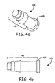
Figure 4a illustrates a front view of plug air vent fitting of the tubular membrane vent in accordance with one embodiment of the present invention. -
Figure 4b illustrates a cross sectional side view of the plug air vent fitting of the tubular membrane vent in accordance with one embodiment of the present invention. -
Figure 5a illustrates a tubular membrane in accordance with one embodiment of the present invention. -
Figure 5b illustrates a tubular membrane in accordance with one embodiment of the present invention. -
Figure 5c illustrates a tubular membrane in accordance with one embodiment of the present invention. -
Figure 5d illustrates a tubular membrane in accordance with one embodiment of the present invention. -
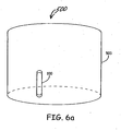
Figure 6a illustrates a perspective view of a tubular membrane vent in accordance with one embodiment of the present invention. -
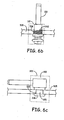
Figure 6b illustrates a side view representation of a tubular membrane vent in accordance with one embodiment of the present invention. -
Figure 6c illustrates a side view representation of a tubular membrane vent in accordance with one embodiment of the present invention. - In the following detailed description, reference is made to the accompanying drawings that form a part hereof, and in which is shown by way of illustration specific illustrative embodiments in which the invention may be practiced. These embodiments are described in sufficient detail to enable those skilled in the art to practice the invention, and it is to be understood that other embodiments may be utilized and that logical, mechanical and electrical changes may be made without departing from the scope of the present invention as defined in
claim 1. -
Figure 1a illustrates a perspective view of a tubular membrane vent prior to assembly, shown generally at 99, in accordance with one embodiment of the present invention. The tubular membrane vent comprises anair vent fitting 117, atubular membrane 121, a tubularstructural support 125, and avent cap 129.Figure 1b shows thetubular membrane vent 99 ofFigure 1a after assembly, shown generally at 100. As illustrated, the tubularstructural support 125 is inserted inside thetubular membrane 121 to provide strength and maintain the shape of thetubular membrane 121. Theair vent fitting 117 is affixed to one end of thetubular membrane 121, and thevent cap 129 is affixed to the opposite end. In one embodiment, the connections between the air vent fitting 117 and thetubular membrane 121 and thevent cap 129 and thetubular membrane 121 are air tight connections. This permits air and pressure transfer only through thetubular membrane 121, preventing leakage at the interconnects. - In the illustrated embodiment, the
tubular membrane 121 comprises a cylinder having a diameter approximate to the diameter of the bore, and a length. In one embodiment, thetubular membrane 121 has a length of between 3 and 10 inches and a diameter between 1/8 and 1 inch. In alternative embodiments, thetubular membrane 121 comprises cylinders larger in diameter than the enclosure opening and diameters smaller than the enclosure opening. In still further embodiments, thetubular membrane 121 comprises alternative shapes, such as atubular membrane 121 having a flared end or a bulboustubular membrane 121. - In one embodiment,
tubular membrane 121 comprises an air permeable hydrophobic material. In an alternative embodiment,tubular membrane 121 comprises air permeable material that is both hydrophobic and oleophobic. In certain embodiments,tubular membrane 121 comprises a polytetrafluoroethylene (PTFE) membrane. In one embodiment,tubular membrane 121 comprises TETRATEX Performance Fabrics by Donaldson Corporation. - In the illustrated embodiment of
Figure 1a , tubularstructural support 125 comprises a metal coil spring. In one embodiment, the metal coil spring is coated with a non-conductive material. In alternative embodiments, nonmetal coil springs are used, such as springs comprising various plastics, elastomer, nylon, or the like. In still other alternative embodiments, non-springstructural supports 125 are implemented. -
Figure 2a depicts a side view representation (along the longitudinal axis) of a threaded air vent fitting, shown generally at 117, of thetubular membrane vent 100 in accordance with one embodiment of the present invention. In the illustrated embodiment, theair vent fitting 117 has anupper tip 122 and alower tip 225 disposed at opposite ends along the longitudinal axis.Figure 2b shows a cross sectional side view representation ofFigure 2a , cut along line A-A' 205 (illustrated inFigure 2c). Figure 2c shows the threaded air vent fitting ofFigure 2a along the radial axis, looking up from thelower tip 225.Figure 2d shows a cross sectional view ofFigure 2c , cut along line B-B' 206 (illustrated inFigure 2b ). The threaded air vent fitting 117 has a body comprising, for example, an acetal engineering plastic such as DELRIN, a polytetrafluoroethylene (PTFE) such as TEFLON, polypropylene, stainless steel, nylon, or other corrosion resistant material. Thelower tip 225 comprises ahexagonal end 227 situated such that torque can be applied, such as by a wrench, along the radial axis. In alternative embodiments, other torque enabling configurations may be used, such as shapes designed to accept the application of rotational force by means of, for example, screw drivers, alien wrenches, and the like. - A plurality of
vents 230 are separated from thelower tip 225 by a radial flaredregion 232 and disposed perpendicular to the longitudinal axis. In certain embodiments, the radial flaredregion 232 promotes the ease of applying torque and protects the plurality ofvents 230. In alternative embodiments the flaredregion 232 is absent. The threaded air vent fitting 117 has ahollow core 233 that extends from theupper tip 122 to the plurality of air vents 230. In alternative embodiments, thehollow core 233 extends slightly beyond the plurality ofvents 230. In further embodiments, thehollow core 233 extends from theupper tip 122 to thelower tip 225. - A
flange 235 is situated adjacent the plurality ofvents 230 along the longitudinal axis. Acircumferential groove 237 is located along the side of theflange 235 nearest theupper tip 122. Disposed within thecircumferential groove 237 is a gasket (not shown). In one embodiment, the gasket is comprised of silicone, rubber, polyurethane, or the like. Adjacent theflange 235 along the longitudinal axis is disposed a threadedregion 242. The threadedregion 242 is designed to couple, for example, with a threaded bore of an electrical enclosure. - A
connector member 245 extends along the longitudinal axis from theupper tip 122 towards the threadedregion 242. In the illustrated embodiment, theconnector member 245 comprises a firstcylindrical section 248 approximately matching the diameter of thetubular membrane 121. A ring shapedprojection 249 is formed along the circumferential face of the firstcylindrical section 248. The ring shapedprojection 249 has afirst diameter 250 disposed near theupper tip 122 and asecond diameter 252 disposed further from theupper tip 122, thefirst diameter 250 corresponding to the diameter of thecylindrical section 248, and thesecond diameter 252 being greater than thecylindrical section 248 in diameter. Between thefirst diameter 250 andsecond diameter 252 is formed atruncated cone 255, as illustrated inFigure 2a . In one embodiment, theconnector member 245 further comprises a secondcylindrical section 260 extending from theupper tip 122 to the firstcylindrical section 248. The secondcylindrical section 260 has a diameter approximately equal to the inner diameter of the tubularstructural support 125. - When the
connector member 245 is inserted intotubular membrane 121, the ring shapedprojection 249 expandstubular membranes 121's diameter. In one embodiment, this expansion causes a tight seal due to the tubular membrane's 121 elasticity and resistance to expansion. Concurrently, the secondcylindrical section 260 couples to tubularstructural support 125, providing additional mechanical strength. In certain embodiments a clamping member (not shown) is implemented along the firstcylindrical section 248 after insertion intotubular membrane 121 to apply additional securing force. In one embodiment, clamping member is comprised of heat shrink tubing, a wire tie, a cable tie, or the like. - In alternative embodiments, securing means other than a threaded fitting are used to attach
tubular membrane vent 100 to an enclosure. Figure's 3a, 3b, and 3c illustrate one possible alternative securing means.Figure 3a shows a perspective view of a plug air vent fitting, shown generally at 315, in accordance with one embodiment of the present invention.Figure 3b illustrates a representation of the same plug air vent fitting 315 in the Y-Z plane.Figure 3c shows a side view representation of plug air vent fitting 315 cut along line C-C' 318 in the X-Y plane. Plug air vent fitting 315 comprises a firstradial portion 317 and a secondradial portion 319, the secondradial portion 319 intersecting the firstradial portion 317 at a ninety degree angle. In one embodiment firstradial portion 317 has a diameter greater than the diameter of secondradial portion 319, and a length less than the length of secondradial portion 319. Firstradial portion 317 has afirst opening 320 and secondradial portion 319 has asecond opening 324,second opening 324 intersectingfirst opening 320 at a right degree angle to form a through air passageway. Firstradial portion 317 comprises aplug 325. In one embodiment, plug 325 has a diameter equal to a corresponding bore in an electrical enclosure. In certain embodiments, plug 325 further comprises a flaredend 330. In the illustrated embodiment, secondradial portion 319 comprises aconnector member 245 as described with respect toFigures 2a and 2b above. - Figure's 4a and 4b illustrate a perspective view and a side view, respectively, of a
vent cap 129, in accordance with one embodiment of the present invention. In one embodiment,vent cap 129 comprises substantially the same material or materials as air vent fitting 117. In the illustrated embodiment,vent cap 129 comprises aconnector member 245 described with respect toFigures 2a and 2b above.Vent cap 129 further comprises a flaredend 405. In alternative embodiments, novent cap 129 is implemented. Where novent cap 129 is implemented, in oneembodiment tubular membrane 121 is sealed at one end by foldingtubular membrane 121 as illustrated in Figure's 5a and 5b. In alternative embodiments,tubular membrane 121 is sealed at rule one end by pinching it off, as illustrated in Figure's 5c and 5d. In one embodiment, an adhesive is used to maintain the seal of the pinched off or folded over end. -
Figure 6a illustrates a perspective view of atubular membrane vent 100 coupled to anelectrical enclosure 503, shown generally at 500, in accordance with one embodiment of the present invention.Figure 6b shows a side view representation of atubular membrane vent 100 having a threaded air vent fitting 117 coupled to anelectrical enclosure wall 505. As illustrated, the threadedregion 242 has a diameter equal to the diameter of a threadedbore 508 in theelectrical enclosure wall 505.Figure 6c shows a side view representation of atubular membrane vent 100 having a plug air vent fitting 315 coupled to anelectrical enclosure wall 505. In the illustrated embodiment, the plug air vent fitting 315 has aplug 325 with a flaredend 330, the plug being the same diameter as abore 510 in theelectrical enclosure wall 505. -
Tubular membrane vent 100 enables enclosures to maintain weather tight status and protection from wind, rain, icing, dust and the intrusion of water when submersed.
Claims (20)
- A membrane vent (100) comprising:an air permeable tubular membrane (121);a tubular structural support (125) adapted to be received by the tubular membrane (121);an air vent fitting (117) attached to the tubular membrane (121) in an airtight manner at a first end, the air vent fitting characterised by:a connector member (245), comprising:a first cylindrical section (248) having a portion with a diameter that approximately matches the tubular membrane, the first cylindrical section having a ring shaped projection (249) comprising a portion with a diameter greater than the diameter of the first cylindrical section; anda second cylindrical section (260), the second cylindrical section having a diameter substantially equal to an inner diameter of the tubular structural support;wherein the connector member is inserted into the tubular membrane in such manner that the ring shaped projection of the first cylindrical section expands the tubular membrane in the air tight manner; andan end cap (129) attached to the tubular membrane (121) in an airtight manner at a second end.
- The membrane vent (100) of claim 1, wherein the tubular structural support (125) comprises a coil spring.
- The membrane vent (100) of claim 2, wherein the coil spring is made of one or more of plastic, polypropylene, elastomer, nylon, and metal.
- The membrane vent (100) of claim 2, wherein the tubular structural support (125) is coated in a non-conducting material.
- The membrane vent (100) of claim 1, wherein the tubular membrane (121) has a length that is larger than its diameter.
- The membrane vent (100) of claim 5, wherein the tubular membrane (121) has a length of between 3 and 10 inches and a diameter between 3.175mm-25.4mm (1/8 and I inch).
- The membrane vent (100) of claim 1, wherein the tubular membrane (121) comprises an air permeable hydrophobic material.
- The membrane vent (100) of claim 1, wherein the tubular membrane (121) comprises an air permeable hydrophobic and oleophobic material.
- The membrane vent (100) of claim 1, wherein the tubular membrane (121) comprises a polytetrafluoroethylene (PTFE) membrane.
- The membrane vent (100) of claim 1, wherein the air vent fitting (117) comprises a threaded air vent fitting.
- The membrane vent (100) of claim 10, wherein one end of the threaded air vent fitting (117) is adapted to accept application of rotational force.
- The membrane vent (100) of claim 1, wherein the air vent fitting (117) comprises a plug air vent fitting (117).
- The membrane vent (100) of claim 1, wherein the tubular membrane (121) is oriented perpendicular to the air vent fitting (117).
- The membrane vent (100) of claim 1, wherein the air vent fitting (117) comprises corrosion resistant material.
- The membrane vent (100) of claim 14, wherein the air vent fitting (117) comprises at least one of delrin, Teflon, polypropylene, stainless steel, nylon, and rubber.
- The membrane vent (100) of claim 1, wherein the vent cap (129) is made of a corrosion resistant material.
- The membrane vent (100) of claim 16, wherein the vent cap (129) is made of at least one of acetal resin, PTFE, polypropylene, stainless steel, and nylon.
- The membrane vent (100) of claim 1, wherein the second end of the tubular membrane (121) is sealed by folding over the second end.
- The membrane vent (100) of claim 1, wherein the second end of the tubular membrane (121) is sealed by pinching off the second end.
- The membrane vent (100) of claim 1, wherein the membrane vent is adapted to mount through a wall of a sealed enclosure.
Applications Claiming Priority (2)
| Application Number | Priority Date | Filing Date | Title |
|---|---|---|---|
| US11/205,658 US7585211B2 (en) | 2005-08-17 | 2005-08-17 | Tubular membrane vent |
| PCT/US2006/032118 WO2007022340A2 (en) | 2005-08-17 | 2006-08-17 | Tubular membrane vent |
Publications (2)
| Publication Number | Publication Date |
|---|---|
| EP1928759A2 EP1928759A2 (en) | 2008-06-11 |
| EP1928759B1 true EP1928759B1 (en) | 2012-10-10 |
Family
ID=37550775
Family Applications (1)
| Application Number | Title | Priority Date | Filing Date |
|---|---|---|---|
| EP06801714A Not-in-force EP1928759B1 (en) | 2005-08-17 | 2006-08-17 | Tubular membrane vent |
Country Status (4)
| Country | Link |
|---|---|
| US (1) | US7585211B2 (en) |
| EP (1) | EP1928759B1 (en) |
| CN (1) | CN101282886B (en) |
| WO (1) | WO2007022340A2 (en) |
Cited By (1)
| Publication number | Priority date | Publication date | Assignee | Title |
|---|---|---|---|---|
| RU2689286C2 (en) * | 2014-02-17 | 2019-05-24 | Итон Лимитед | Oxygen sensor comprising a large diameter optical fiber with a coated tip |
Families Citing this family (11)
| Publication number | Priority date | Publication date | Assignee | Title |
|---|---|---|---|---|
| JP4870022B2 (en) * | 2007-05-16 | 2012-02-08 | 住友重機械工業株式会社 | Decelerator |
| US20090263892A1 (en) * | 2008-04-18 | 2009-10-22 | Henry Joseph Cattadoris | Float valve for cell culture vessel |
| US8177082B2 (en) | 2008-04-18 | 2012-05-15 | Corning Incorporated | Flexible membrane valve for cell culture vessel |
| DE102010036294A1 (en) | 2010-09-03 | 2012-03-08 | Hydac Filtertechnik Gmbh | System for ventilation of containers of fluid volume |
| US8574045B2 (en) * | 2010-12-17 | 2013-11-05 | Dina Warner | Frost-free vent assembly |
| FR2987427B1 (en) * | 2012-01-27 | 2015-03-20 | Valeo Illuminacion | VENTILATION OF A LIGHTING OR SIGNALING DEVICE HOUSING OF A VEHICLE |
| US10228009B2 (en) | 2015-09-21 | 2019-03-12 | Apple Inc. | Vent for portable electronics combined with enclosure mounting fastener |
| CN107014026A (en) * | 2017-05-13 | 2017-08-04 | 昆山斯莱姆节能科技有限公司 | A kind of fast joint structure of pressure fan and Rose Box |
| CN106996615A (en) * | 2017-05-13 | 2017-08-01 | 昆山斯莱姆节能科技有限公司 | A kind of communal bathroom ventilation equipment |
| WO2021119843A1 (en) * | 2019-12-20 | 2021-06-24 | Shawcor Ltd. | Pressure equalization in composite pipes |
| DE102020104039B4 (en) * | 2020-02-17 | 2025-11-27 | Ifm Electronic Gmbh | Housing with vent sleeve as well as measuring instrument and pressure gauge for process measurement technology with such a housing |
Citations (1)
| Publication number | Priority date | Publication date | Assignee | Title |
|---|---|---|---|---|
| US3868325A (en) * | 1973-08-24 | 1975-02-25 | Sethco Mfg Corp | Filter tube adapters |
Family Cites Families (31)
| Publication number | Priority date | Publication date | Assignee | Title |
|---|---|---|---|---|
| US2016294A (en) * | 1933-05-26 | 1935-10-08 | Citizens Trust Company | Air-method cleaner |
| NL78582C (en) * | 1953-08-24 | 1900-01-01 | ||
| US3033911A (en) * | 1958-07-30 | 1962-05-08 | Electric Storage Battery Co | Vent plug |
| US3394815A (en) * | 1966-03-25 | 1968-07-30 | Henry Mfg Co Inc | Tubular filter elements |
| US3750889A (en) * | 1971-06-17 | 1973-08-07 | W Acosta | Filter tube |
| US3866789A (en) * | 1974-01-16 | 1975-02-18 | Reliance Electric Co | Vent plug for gear case |
| US4032311A (en) * | 1976-06-01 | 1977-06-28 | Dacor Corporation | Tank filter |
| US4276069A (en) * | 1979-09-12 | 1981-06-30 | American Air Filter Company, Inc. | Filter arrangement |
| DE3007075A1 (en) * | 1980-02-26 | 1981-09-10 | Peter 5330 Königswinter Grundmann | Chemical seal water emergency desalination kit - made of collapsible plastic hose with embedded steel wire spiral |
| US4392872A (en) * | 1981-04-03 | 1983-07-12 | Monterey Manufacturing, Inc. | Air bleeder valve for waterbed mattresses |
| US4442004A (en) * | 1982-07-01 | 1984-04-10 | Osmonics, Inc. | Biasing arrangement and filter unit for a filtering apparatus |
| US4581137A (en) * | 1984-10-19 | 1986-04-08 | Ozonics Corporation | Gas diffuser tube assembly |
| US4594082A (en) * | 1984-11-19 | 1986-06-10 | Harris Corporation | Dehydrating air-filtering apparatus |
| US4809144A (en) * | 1986-12-11 | 1989-02-28 | Stanley Electric Co., Ltd. | Vehicle headlamp with a vent hole |
| DE3815642A1 (en) * | 1988-05-07 | 1989-11-16 | Bosch Gmbh Robert | PRESSURE COMPENSATING ELEMENT FOR AN ELECTRICAL SWITCHGEAR |
| US5034165A (en) * | 1990-07-26 | 1991-07-23 | Willinger Brothers, Inc. | Air stone |
| FR2674446B1 (en) * | 1991-03-29 | 1993-07-09 | Pall France Services | FILTRATION AND COMMUNICATION DEVICE BETWEEN THE ATMOSPHERE AND THE INTERIOR OF A CRANKCASE. |
| US5230131A (en) * | 1991-08-28 | 1993-07-27 | Hobson Jr Russell | Recyclable flexible filter tube and method for recycling filter tubes |
| US5353949A (en) * | 1992-09-21 | 1994-10-11 | Pall Corporation | Vent filter assembly |
| US5341951A (en) * | 1993-04-30 | 1994-08-30 | The Raymond Corporation | Air-filtering hydraulic reservoir breather cap |
| US5456834A (en) * | 1993-12-16 | 1995-10-10 | W. L. Gore & Associates, Inc. | Device for mounting a filter sleeve to a filter apparatus |
| US5417743A (en) * | 1994-01-21 | 1995-05-23 | W. L. Gore & Associates, Inc. | Self-adhesive vent filter and adsorbent assembly with a diffusion tube |
| DE4409970A1 (en) * | 1994-03-23 | 1995-09-28 | Hydac Filtertechnik Gmbh | Support body for filter elements |
| US5464469A (en) * | 1994-08-23 | 1995-11-07 | Moore Products Co. | Vent system for blocking the passage of liquid while permitting passage of gas |
| US5522769A (en) * | 1994-11-17 | 1996-06-04 | W. L. Gore & Associates, Inc. | Gas-permeable, liquid-impermeable vent cover |
| US5901867A (en) * | 1995-10-25 | 1999-05-11 | Roberts Polypro, Inc. | Ventable cap |
| JP3219700B2 (en) * | 1996-09-18 | 2001-10-15 | 日東電工株式会社 | Vent filter member |
| US5814118A (en) * | 1996-11-18 | 1998-09-29 | Nuclear Filter Technology, Inc. | HEPA filter for venting chambers |
| US5954846A (en) * | 1997-10-23 | 1999-09-21 | Alfa Laval Agri Inc. | Efficient, replaceable air filter system for milking machine pulsators |
| US6579342B2 (en) * | 2001-02-07 | 2003-06-17 | Pall Corporation | Oleophobic membrane materials by oligomer polymerization for filter venting applications |
| JP2005132165A (en) | 2003-10-29 | 2005-05-26 | Nsk Ltd | Electric power steering device |
-
2005
- 2005-08-17 US US11/205,658 patent/US7585211B2/en active Active
-
2006
- 2006-08-17 EP EP06801714A patent/EP1928759B1/en not_active Not-in-force
- 2006-08-17 WO PCT/US2006/032118 patent/WO2007022340A2/en not_active Ceased
- 2006-08-17 CN CN2006800373693A patent/CN101282886B/en not_active Expired - Fee Related
Patent Citations (1)
| Publication number | Priority date | Publication date | Assignee | Title |
|---|---|---|---|---|
| US3868325A (en) * | 1973-08-24 | 1975-02-25 | Sethco Mfg Corp | Filter tube adapters |
Cited By (1)
| Publication number | Priority date | Publication date | Assignee | Title |
|---|---|---|---|---|
| RU2689286C2 (en) * | 2014-02-17 | 2019-05-24 | Итон Лимитед | Oxygen sensor comprising a large diameter optical fiber with a coated tip |
Also Published As
| Publication number | Publication date |
|---|---|
| CN101282886A (en) | 2008-10-08 |
| CN101282886B (en) | 2010-09-29 |
| WO2007022340A2 (en) | 2007-02-22 |
| US7585211B2 (en) | 2009-09-08 |
| EP1928759A2 (en) | 2008-06-11 |
| US20070042704A1 (en) | 2007-02-22 |
| WO2007022340A3 (en) | 2007-04-19 |
Similar Documents
| Publication | Publication Date | Title |
|---|---|---|
| US7585211B2 (en) | Tubular membrane vent | |
| EP2679515B1 (en) | Venting device | |
| US7357709B2 (en) | Metal vent | |
| CN109417856B (en) | Ventilation Department | |
| US5522769A (en) | Gas-permeable, liquid-impermeable vent cover | |
| CN100455845C (en) | Spring-loaded and self-locking cable clamping device | |
| CN102361286A (en) | Sealing structure for wire lead-out hole and method for sealing wire lead-out hole | |
| EP2229245B1 (en) | Arrangement, ventilation arm, ventilation system | |
| CN109314380B (en) | Wire grommets and harnesses | |
| US20030222359A1 (en) | Apparatus for aerating water | |
| US20150270693A1 (en) | Resilient aperture cover | |
| JP6424793B2 (en) | Grommet and wire harness | |
| US20170219139A1 (en) | Rotatable axially securing and pressure-resistant line connection | |
| CN112431950A (en) | Automatic control valve and flow control equipment | |
| US6360540B1 (en) | Low vent pressure master cylinder reservoir cap diaphragm | |
| CN102192346B (en) | Ventilation valve | |
| US4974745A (en) | Pressure compensating element for electrical device enclosure | |
| EP3564563B1 (en) | Holding device which can be fixed to a wall for holding a tube | |
| US11285802B2 (en) | All in one fuel tank assembly | |
| CN221614176U (en) | Antenna end cover assembly and base station antenna | |
| KR101568793B1 (en) | Connecting Srtucture Of Pipes | |
| WO2018135389A1 (en) | Ventilation member and harness | |
| US20150136472A1 (en) | Wire seal assembly | |
| US12126152B2 (en) | Ball mount with integrated cable gland | |
| US20190170207A1 (en) | Hydraulic mount |
Legal Events
| Date | Code | Title | Description |
|---|---|---|---|
| PUAI | Public reference made under article 153(3) epc to a published international application that has entered the european phase |
Free format text: ORIGINAL CODE: 0009012 |
|
| 17P | Request for examination filed |
Effective date: 20080227 |
|
| AK | Designated contracting states |
Kind code of ref document: A2 Designated state(s): AT BE BG CH CY CZ DE DK EE ES FI FR GB GR HU IE IS IT LI LT LU LV MC NL PL PT RO SE SI SK TR |
|
| 17Q | First examination report despatched |
Effective date: 20100226 |
|
| GRAP | Despatch of communication of intention to grant a patent |
Free format text: ORIGINAL CODE: EPIDOSNIGR1 |
|
| RIC1 | Information provided on ipc code assigned before grant |
Ipc: B65D 51/16 20060101AFI20120116BHEP Ipc: B01D 63/06 20060101ALI20120116BHEP Ipc: B01D 69/10 20060101ALI20120116BHEP Ipc: H05K 5/06 20060101ALI20120116BHEP Ipc: B01D 65/00 20060101ALI20120116BHEP Ipc: H05K 5/02 20060101ALI20120116BHEP |
|
| GRAS | Grant fee paid |
Free format text: ORIGINAL CODE: EPIDOSNIGR3 |
|
| DAX | Request for extension of the european patent (deleted) | ||
| GRAA | (expected) grant |
Free format text: ORIGINAL CODE: 0009210 |
|
| AK | Designated contracting states |
Kind code of ref document: B1 Designated state(s): AT BE BG CH CY CZ DE DK EE ES FI FR GB GR HU IE IS IT LI LT LU LV MC NL PL PT RO SE SI SK TR |
|
| REG | Reference to a national code |
Ref country code: GB Ref legal event code: FG4D |
|
| REG | Reference to a national code |
Ref country code: CH Ref legal event code: EP Ref country code: AT Ref legal event code: REF Ref document number: 578850 Country of ref document: AT Kind code of ref document: T Effective date: 20121015 |
|
| REG | Reference to a national code |
Ref country code: IE Ref legal event code: FG4D |
|
| REG | Reference to a national code |
Ref country code: DE Ref legal event code: R096 Ref document number: 602006032429 Country of ref document: DE Effective date: 20121206 |
|
| REG | Reference to a national code |
Ref country code: SE Ref legal event code: TRGR |
|
| PG25 | Lapsed in a contracting state [announced via postgrant information from national office to epo] |
Ref country code: SI Free format text: LAPSE BECAUSE OF FAILURE TO SUBMIT A TRANSLATION OF THE DESCRIPTION OR TO PAY THE FEE WITHIN THE PRESCRIBED TIME-LIMIT Effective date: 20121010 |
|
| REG | Reference to a national code |
Ref country code: NL Ref legal event code: VDEP Effective date: 20121010 |
|
| REG | Reference to a national code |
Ref country code: AT Ref legal event code: MK05 Ref document number: 578850 Country of ref document: AT Kind code of ref document: T Effective date: 20121010 |
|
| REG | Reference to a national code |
Ref country code: LT Ref legal event code: MG4D |
|
| PG25 | Lapsed in a contracting state [announced via postgrant information from national office to epo] |
Ref country code: LT Free format text: LAPSE BECAUSE OF FAILURE TO SUBMIT A TRANSLATION OF THE DESCRIPTION OR TO PAY THE FEE WITHIN THE PRESCRIBED TIME-LIMIT Effective date: 20121010 Ref country code: NL Free format text: LAPSE BECAUSE OF FAILURE TO SUBMIT A TRANSLATION OF THE DESCRIPTION OR TO PAY THE FEE WITHIN THE PRESCRIBED TIME-LIMIT Effective date: 20121010 Ref country code: IS Free format text: LAPSE BECAUSE OF FAILURE TO SUBMIT A TRANSLATION OF THE DESCRIPTION OR TO PAY THE FEE WITHIN THE PRESCRIBED TIME-LIMIT Effective date: 20130210 |
|
| PG25 | Lapsed in a contracting state [announced via postgrant information from national office to epo] |
Ref country code: PL Free format text: LAPSE BECAUSE OF FAILURE TO SUBMIT A TRANSLATION OF THE DESCRIPTION OR TO PAY THE FEE WITHIN THE PRESCRIBED TIME-LIMIT Effective date: 20121010 Ref country code: PT Free format text: LAPSE BECAUSE OF FAILURE TO SUBMIT A TRANSLATION OF THE DESCRIPTION OR TO PAY THE FEE WITHIN THE PRESCRIBED TIME-LIMIT Effective date: 20130211 Ref country code: CY Free format text: LAPSE BECAUSE OF FAILURE TO SUBMIT A TRANSLATION OF THE DESCRIPTION OR TO PAY THE FEE WITHIN THE PRESCRIBED TIME-LIMIT Effective date: 20121010 Ref country code: GR Free format text: LAPSE BECAUSE OF FAILURE TO SUBMIT A TRANSLATION OF THE DESCRIPTION OR TO PAY THE FEE WITHIN THE PRESCRIBED TIME-LIMIT Effective date: 20130111 Ref country code: LV Free format text: LAPSE BECAUSE OF FAILURE TO SUBMIT A TRANSLATION OF THE DESCRIPTION OR TO PAY THE FEE WITHIN THE PRESCRIBED TIME-LIMIT Effective date: 20121010 Ref country code: BE Free format text: LAPSE BECAUSE OF FAILURE TO SUBMIT A TRANSLATION OF THE DESCRIPTION OR TO PAY THE FEE WITHIN THE PRESCRIBED TIME-LIMIT Effective date: 20121010 |
|
| PG25 | Lapsed in a contracting state [announced via postgrant information from national office to epo] |
Ref country code: AT Free format text: LAPSE BECAUSE OF FAILURE TO SUBMIT A TRANSLATION OF THE DESCRIPTION OR TO PAY THE FEE WITHIN THE PRESCRIBED TIME-LIMIT Effective date: 20121010 |
|
| PG25 | Lapsed in a contracting state [announced via postgrant information from national office to epo] |
Ref country code: EE Free format text: LAPSE BECAUSE OF FAILURE TO SUBMIT A TRANSLATION OF THE DESCRIPTION OR TO PAY THE FEE WITHIN THE PRESCRIBED TIME-LIMIT Effective date: 20121010 Ref country code: BG Free format text: LAPSE BECAUSE OF FAILURE TO SUBMIT A TRANSLATION OF THE DESCRIPTION OR TO PAY THE FEE WITHIN THE PRESCRIBED TIME-LIMIT Effective date: 20130110 Ref country code: DK Free format text: LAPSE BECAUSE OF FAILURE TO SUBMIT A TRANSLATION OF THE DESCRIPTION OR TO PAY THE FEE WITHIN THE PRESCRIBED TIME-LIMIT Effective date: 20121010 Ref country code: SK Free format text: LAPSE BECAUSE OF FAILURE TO SUBMIT A TRANSLATION OF THE DESCRIPTION OR TO PAY THE FEE WITHIN THE PRESCRIBED TIME-LIMIT Effective date: 20121010 Ref country code: CZ Free format text: LAPSE BECAUSE OF FAILURE TO SUBMIT A TRANSLATION OF THE DESCRIPTION OR TO PAY THE FEE WITHIN THE PRESCRIBED TIME-LIMIT Effective date: 20121010 |
|
| PLBE | No opposition filed within time limit |
Free format text: ORIGINAL CODE: 0009261 |
|
| STAA | Information on the status of an ep patent application or granted ep patent |
Free format text: STATUS: NO OPPOSITION FILED WITHIN TIME LIMIT |
|
| PG25 | Lapsed in a contracting state [announced via postgrant information from national office to epo] |
Ref country code: IT Free format text: LAPSE BECAUSE OF FAILURE TO SUBMIT A TRANSLATION OF THE DESCRIPTION OR TO PAY THE FEE WITHIN THE PRESCRIBED TIME-LIMIT Effective date: 20121010 Ref country code: RO Free format text: LAPSE BECAUSE OF FAILURE TO SUBMIT A TRANSLATION OF THE DESCRIPTION OR TO PAY THE FEE WITHIN THE PRESCRIBED TIME-LIMIT Effective date: 20121010 |
|
| 26N | No opposition filed |
Effective date: 20130711 |
|
| PG25 | Lapsed in a contracting state [announced via postgrant information from national office to epo] |
Ref country code: ES Free format text: LAPSE BECAUSE OF FAILURE TO SUBMIT A TRANSLATION OF THE DESCRIPTION OR TO PAY THE FEE WITHIN THE PRESCRIBED TIME-LIMIT Effective date: 20130121 |
|
| REG | Reference to a national code |
Ref country code: DE Ref legal event code: R097 Ref document number: 602006032429 Country of ref document: DE Effective date: 20130711 |
|
| REG | Reference to a national code |
Ref country code: CH Ref legal event code: PL |
|
| PG25 | Lapsed in a contracting state [announced via postgrant information from national office to epo] |
Ref country code: CH Free format text: LAPSE BECAUSE OF NON-PAYMENT OF DUE FEES Effective date: 20130831 Ref country code: MC Free format text: LAPSE BECAUSE OF FAILURE TO SUBMIT A TRANSLATION OF THE DESCRIPTION OR TO PAY THE FEE WITHIN THE PRESCRIBED TIME-LIMIT Effective date: 20121010 Ref country code: LI Free format text: LAPSE BECAUSE OF NON-PAYMENT OF DUE FEES Effective date: 20130831 |
|
| REG | Reference to a national code |
Ref country code: IE Ref legal event code: MM4A |
|
| PG25 | Lapsed in a contracting state [announced via postgrant information from national office to epo] |
Ref country code: IE Free format text: LAPSE BECAUSE OF NON-PAYMENT OF DUE FEES Effective date: 20130817 |
|
| PG25 | Lapsed in a contracting state [announced via postgrant information from national office to epo] |
Ref country code: TR Free format text: LAPSE BECAUSE OF FAILURE TO SUBMIT A TRANSLATION OF THE DESCRIPTION OR TO PAY THE FEE WITHIN THE PRESCRIBED TIME-LIMIT Effective date: 20121010 |
|
| PG25 | Lapsed in a contracting state [announced via postgrant information from national office to epo] |
Ref country code: HU Free format text: LAPSE BECAUSE OF FAILURE TO SUBMIT A TRANSLATION OF THE DESCRIPTION OR TO PAY THE FEE WITHIN THE PRESCRIBED TIME-LIMIT; INVALID AB INITIO Effective date: 20060817 Ref country code: LU Free format text: LAPSE BECAUSE OF NON-PAYMENT OF DUE FEES Effective date: 20130817 |
|
| REG | Reference to a national code |
Ref country code: FR Ref legal event code: PLFP Year of fee payment: 10 |
|
| REG | Reference to a national code |
Ref country code: FR Ref legal event code: PLFP Year of fee payment: 11 |
|
| REG | Reference to a national code |
Ref country code: FR Ref legal event code: PLFP Year of fee payment: 12 |
|
| PGFP | Annual fee paid to national office [announced via postgrant information from national office to epo] |
Ref country code: DE Payment date: 20170829 Year of fee payment: 12 Ref country code: GB Payment date: 20170829 Year of fee payment: 12 Ref country code: FR Payment date: 20170825 Year of fee payment: 12 Ref country code: FI Payment date: 20170829 Year of fee payment: 12 |
|
| PGFP | Annual fee paid to national office [announced via postgrant information from national office to epo] |
Ref country code: SE Payment date: 20170829 Year of fee payment: 12 |
|
| REG | Reference to a national code |
Ref country code: GB Ref legal event code: 732E Free format text: REGISTERED BETWEEN 20171130 AND 20171206 |
|
| REG | Reference to a national code |
Ref country code: DE Ref legal event code: R119 Ref document number: 602006032429 Country of ref document: DE |
|
| REG | Reference to a national code |
Ref country code: SE Ref legal event code: EUG |
|
| GBPC | Gb: european patent ceased through non-payment of renewal fee |
Effective date: 20180817 |
|
| PG25 | Lapsed in a contracting state [announced via postgrant information from national office to epo] |
Ref country code: FI Free format text: LAPSE BECAUSE OF NON-PAYMENT OF DUE FEES Effective date: 20180817 |
|
| PG25 | Lapsed in a contracting state [announced via postgrant information from national office to epo] |
Ref country code: SE Free format text: LAPSE BECAUSE OF NON-PAYMENT OF DUE FEES Effective date: 20180818 |
|
| PG25 | Lapsed in a contracting state [announced via postgrant information from national office to epo] |
Ref country code: DE Free format text: LAPSE BECAUSE OF NON-PAYMENT OF DUE FEES Effective date: 20190301 |
|
| PG25 | Lapsed in a contracting state [announced via postgrant information from national office to epo] |
Ref country code: FR Free format text: LAPSE BECAUSE OF NON-PAYMENT OF DUE FEES Effective date: 20180831 |
|
| PG25 | Lapsed in a contracting state [announced via postgrant information from national office to epo] |
Ref country code: GB Free format text: LAPSE BECAUSE OF NON-PAYMENT OF DUE FEES Effective date: 20180817 |