EP1928548B1 - Procedes et systemes de prevision de valeur seuil de defibrillation - Google Patents
Procedes et systemes de prevision de valeur seuil de defibrillation Download PDFInfo
- Publication number
- EP1928548B1 EP1928548B1 EP06789564A EP06789564A EP1928548B1 EP 1928548 B1 EP1928548 B1 EP 1928548B1 EP 06789564 A EP06789564 A EP 06789564A EP 06789564 A EP06789564 A EP 06789564A EP 1928548 B1 EP1928548 B1 EP 1928548B1
- Authority
- EP
- European Patent Office
- Prior art keywords
- heart
- defibrillation
- electrode
- energy
- electrodes
- Prior art date
- Legal status (The legal status is an assumption and is not a legal conclusion. Google has not performed a legal analysis and makes no representation as to the accuracy of the status listed.)
- Not-in-force
Links
Images

Classifications
-
- A—HUMAN NECESSITIES
- A61—MEDICAL OR VETERINARY SCIENCE; HYGIENE
- A61N—ELECTROTHERAPY; MAGNETOTHERAPY; RADIATION THERAPY; ULTRASOUND THERAPY
- A61N1/00—Electrotherapy; Circuits therefor
- A61N1/18—Applying electric currents by contact electrodes
- A61N1/32—Applying electric currents by contact electrodes alternating or intermittent currents
- A61N1/38—Applying electric currents by contact electrodes alternating or intermittent currents for producing shock effects
- A61N1/39—Heart defibrillators
- A61N1/3925—Monitoring; Protecting
- A61N1/3937—Monitoring output parameters
- A61N1/3943—Monitoring output parameters for threshold determination
Definitions
- This patent document pertains generally to defibrillation threshold prediction, and more particularly, but not by way of limitation, to cardiac function management methods and systems.
- cardiac arrhythmias When functioning properly, the human heart maintains its own intrinsic rhythm, and is capable of pumping adequate blood throughout the body's circulatory system. However, some people have irregular cardiac rhythms, referred to as cardiac arrhythmias. Such arrhythmias result in diminished blood circulation.
- One mode of treating cardiac arrhythmias uses drug therapy. Drugs are often effective at restoring normal heart rhythms. However, drug therapy is not always effective for treating arrhythmias of certain patients. For such patients, an alternative mode of treatment is needed.
- One such alternative mode of treatment includes the use of a cardiac rhythm management system. Such systems are often implanted in the patient and deliver therapy to the heart.
- Pacers deliver timed sequences of low energy electric stimuli, called pace pulses, to the heart, such as via an intravascular leadwire or catheter (referred to as a "lead") having one or more electrodes disposed in or about the heart. Heart contractions are initiated in response to such pace pulses (this is referred to as "capturing" the heart). By properly timing the delivery of pace pulses, the heart can be induced to contract in proper rhythm, greatly improving its efficiency as a pump. Pacers are often used to treat patients with bradyarrhythmias, that is, hearts that beat too slowly, or irregularly.
- Cardiac rhythm management systems also include defibrillators that are capable of delivering higher energy electric stimuli to the heart. Such defibrillators also include cardioverters, which synchronize the delivery of such stimuli to portions of sensed intrinsic heart activity signals. Defibrillators are often used to treat patients with tachyarrhythmias, that is, hearts that beat too quickly. Such too-fast heart rhythms also cause diminished blood circulation because the heart is not allowed sufficient time to fill with blood before contracting to expel the blood. Such pumping by the heart is inefficient.
- a defibrillator is capable of delivering a high energy electric stimulus that is sometimes referred to as a defibrillation countershock, also referred to simply as a "shock."
- the countershock interrupts the tachyarrhythmia, allowing the heart to reestablish a normal rhythm for the efficient pumping of blood.
- cardiac rhythm management systems also include, among other things, pacer/defibrillators that combine the functions of pacers and defibrillators, drug delivery devices, and any other implantable or external systems or devices for diagnosing or treating cardiac arrhythmias.
- Ventricular and atrial fibrillation are probabilistic phenomena that observe a dose-response relationship with respect to shock strength.
- the ventricular defibrillation threshold is the smallest amount of energy that can be delivered to the heart to reliably revert ventricular fibrillation to a normal rhythm.
- the atrial defibrillation threshold is the threshold amount of energy that will terminate an atrial fibrillation.
- defibrillation thresholds vary from patient to patient, and may even vary within a patient depending on the placement of the electrodes used to deliver the therapy.
- the defibrillation thresholds In order to ensure the efficacy of such therapy and to maximize the longevity of the battery source of such therapy energy, the defibrillation thresholds must be determined so that the defibrillation energy can be safely set above the threshold value but not at so large of a value so as to waste energy and shorten the usable life of the implanted device.
- One technique for determining the defibrillation threshold is to induce the targeted tachyarrhythmia (e.g., ventricular fibrillation), and then apply shocks of varying magnitude to determine the energy needed to convert the arrhythmia into a normal heart rhythm.
- tachyarrhythmia e.g., ventricular fibrillation
- this requires imposing the risks and discomfort associated with both the arrhythmia and the therapy. Electric energy delivered to the heart has the potential to both cause myocardial injury and subject the patient to pain.
- defibrillation thresholds are being obtained in order to assist the physician in determining optimal lead placement, these disadvantages are compounded as the procedure is repeated for different potential lead placements.
- the defibrillation threshold In another technique for determining the defibrillation threshold, referred to as the "upper limit of vulnerability" technique, a patient in a state of normal heart rhythm is shocked during the vulnerable (T-wave) period of the cardiac cycle during which time the heart tissue is undergoing repolarization. Shocks of varying magnitude are applied until fibrillation is induced. Of course, after such fibrillation is induced, the patient must be again shocked in order to interrupt the arrhythmia and reestablish a normal heart rhythm. In this technique, the corresponding fibrillation-inducing shock magnitude is then related to a defibrillation threshold energy using a theoretical model.
- the upper limit of vulnerability technique also suffers from imposing the risks and discomfort associated with both the arrhythmia and the shock therapy.
- US 2004/0138714 discloses a cardiac rhythm management device that predicts defibrillation thresholds without applying defibrillation shocks or subjecting the patient to fibrillation.
- An elliptical model of the electrical field distribution around the dipole foci formed by the defibrillation electrodes can be used to estimate the defibrillation energy needed to obtain a desired electrical field at the periphery of the heart.
- An example method includes delivering a first nonstimulating nondefibrillating and nonfibrillation-inducing energy at a first internal thoracic location and detecting a first resulting electric signal at a second internal thoracic location in or near a target region of a heart.
- the first resulting electric signal provides an indication of a first electric field strength in the target region.
- the method further includes estimating a defibrillation threshold using the first nonstimulating nondefibrillating and nonfibrillation-inducing energy, the first resulting electric signal, and a target electric field strength at the target region of the heart.
- Another example method includes delivering a first nonstimulating nondefibrillating and nonfibrillation-inducing energy at a first internal thoracic location and detecting a first resulting electric signal at a second internal thoracic location in or near a target region of a heart.
- the first resulting electric signal provides an indication of a first electric field strength in the target region.
- the method further includes estimating a first defibrillation threshold using the first nonstimulating nondefibrillating and nonfibrillation-inducing energy, the first resulting electric signal, and a target electric field strength.
- the method also includes delivering a second nonstimulating nondefibrillating and nonfibrillation-inducing energy at the first internal thoracic location, detecting a second resulting electric signal at the second internal thoracic location, and determining a change in a defibrillation threshold using the first resulting electric signal and the second resulting electric signal.
- Another example method includes delivering a first nonstimulating nondefibrillating and nonfibrillation-inducing energy to a thorax using a first nonstimulating defibrillation configuration, and detecting a first resulting electric signal at an internal thoracic location in or near a target region of a heart.
- the first resulting electric signal provides an indication of a first electric field strength in the target region.
- the method also includes delivering a second non stimulating nondefibrillating and nonfibrillation-inducing energy to the thorax using a second defibrillation configuration and detecting a second resulting electric signal at the internal thoracic location.
- the second resulting electric signal provides an indication of a second electric field strength in the target region of the heart during delivery of the nonstimulating nondefibrillating and nonfibrillation-inducing energy using the second defibrillation configuration.
- the method further includes estimating at least one defibrillation threshold using at least one target electric field strength and at least one of the first and second resulting electric signals.
- delivering a first nonstimulating nondefibrillating and nonfibrillation-inducing energy to a thorax using a first defibrillation configuration includes delivering the energy through a plurality of electrodes, and delivering a second nonstimulating nondefibrillating and nonfibrillation-inducing energy to the thorax using a second defibrillation configuration includes changing a configuration of the plurality of electrodes and then delivering the energy through the plurality of electrodes.
- changing a configuration of the plurality of electrodes includes changing a location of at least one electrode or electrically connecting at least one electrode to at least one other electrode.
- delivering a first nonstimulating nondefibrillating and nonfibrillation-inducing energy includes delivering the first nonstimulating nondefibrillating and nonfibrillation-inducing energy using a first electrode configuration
- delivering a second nonstimulating nondefibrillating and nonfibrillation-inducing energy includes delivering the second nonstimutaling nondefibrillating and nonfibrillation-inducing energy using a second electrode configuration, and estimating at least one defibrillation threshold selecting an electrode configuration that produces a smaller defibrillation threshold for delivery of an antitachyarrhythmia therapy therefrom.
- An example system includes an energy module adapted to deliver a nonstimulating nondefibrillating and nonfibrillation-inducing energy using at least a first electrode at a first internal thoracic location, a response signal module adapted to detect a resulting signal using at least a second electrode at a second internal thoracic location in or near a target region of a heart, the responsive signal resulting from the delivery of the energy and providing an indication of an electric field strength at the second internal thoracic location, and a controller communicatively coupled to the energy module and the response signal module, the controller adapted to estimate a defibrillation threshold using the nonstimulating nondefibrillating and nonfibrillation-inducing energy and the resulting signal.
- the controller is adapted to compare a detected resulting signal with a previous detected resulting signal to detect a change in the resulting signal indicative of a defibrillation threshold change, or to compare an estimated defibrillation threshold to a previously estimated defibrillation threshold to detect a change in the defibrillation threshold.
- the controller is adapted to deliver a notification if an changed defibrillation threshold is detected or to increase an energy level of an antitachyarrhythmia therapy if an increased defibrillation threshold is detected.
- the present invention relates, in part, to using different electrode configurations to obtain different detected electrical signals for use in estimating defibrillation threshold energies.
- the description hereinafter includes examples of obtaining such different electrode configurations by physically manipulating in vivo the leads on which an electrode is provide, these examples are strictly by way of background illustration, and do not form part of the invention claimed herein.
- implantable medical devices including, but not limited to, implantable cardiac function management systems such as pacemakers, cardioverter/defibrillators, pacer/defibrillators, biventricular or other multi-site coordination or resynchronization devices, and drug delivery systems for managing cardiac rhythm.
- implantable cardiac function management systems such as pacemakers, cardioverter/defibrillators, pacer/defibrillators, biventricular or other multi-site coordination or resynchronization devices, and drug delivery systems for managing cardiac rhythm.
- implantable cardiac function management systems such as pacemakers, cardioverter/defibrillators, pacer/defibrillators, biventricular or other multi-site coordination or resynchronization devices, and drug delivery systems for managing cardiac rhythm.
- unimplanted devices including, but not limited to, external pacemakers, cardioverter/defibrillators, pacer/defibrillators, biventricular or other multi-site coordination or resynchronization devices, monitors, programmers and recorders.
- An estimated defibrillation threshold energy is determined based upon a desired electric field strength in a target region of the heart.
- an energy is delivered at a first internal thoracic location, such as a location in, on, or near the heart.
- the delivered energy is preferably, but not necessarily, a nonstimulating nondefibrillating and nonfibrillation-inducing energy.
- a resulting electric signal is detected at a second internal thoracic location in or near the target region of the heart.
- the energy is delivered to the right side of the heart, and the target region is in, on, or near the left apical region of the heart and/or a left free lateral wall.
- the resulting electric signal is used to estimate the defibrillation threshold energy required to create the desired electric field strength in the target region.
- the estimated defibrillation threshold energy is determined using a ratio of the desired (or "target") electric field strength (e.g. 5 volts/cm) to the electric field strength produced by the delivered energy.
- a ventricular and/or atrial defibrillation threshold is determined.
- actual measurement of a resulting electric field in or near the target region avoids reliance on fluoroscopic distance measurement and electric field modeling computations.
- defibrillation thresholds are determined for multiple shock electrode configurations, allowing for selection of a low-threshold configuration that can be used to conserve energy and prolong battery life.
- An increase in defibrillation threshold may be indicative of hypertrophy, ventricle dilation, ischemia or myocardial infarction, scar tissue, or lead dislodgement.
- a defibrillation therapy energy is increased, or a notification such as a warning is delivered.
- the present techniques typically reduce risks to a patient by permitting defibrillation threshold determination without inducing fibrillation or delivering a fibrillation-inducing shock energy. For example, using the present techniques, a very sick patient for whom a doctor hesitates to do a standard defibrillating test to determine a defibrillation threshold could be fitted with a defibrillator while avoiding delivery of a defibrillating shock to test the patient's defibrillation threshold. In another example, patients are screened using the present techniques to identify patients suitable for defibrillation.
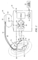
- FIG 1 is a schematic/block diagram illustrating generally, by way of example, and not by way of limitation, one embodiment of portions of a cardiac rhythm management system 100 and portions of an environment in which the present system 100 and associated techniques are used.
- the system 100 includes, among other things, cardiac rhythm management device 105 and leadwires ("leads") 110, 180 for communicating signals between device 105 and a portion of a living organism, such as heart 115.
- cardiac rhythm management device 105 include, but are not limited to, bradycardia and antitachycardia pacemakers, cardioverters, defibrillators, combination pacemaker/defibrillators, drug delivery devices, and any other implantable or external cardiac rhythm management apparatus capable of diagnosing or providing therapy to heart 115.
- FIG. 1 illustrates, in an exploded view block diagram form, portions of an example device 105.
- the illustrated device 105 is coupled to leads 110 and 180 that extend toward the heart; however, the illustrated connection lines associated with the exploded view are illustrative only.
- test energy module 150 generates an energy that is delivered by electrodes, such as two or more of electrodes 125, 130, and/or 140, at an internal thoracic location, such as a location in, on, or around the heart.
- electrodes 125, 130, and 140 all act as separate electrodes.
- two or more electrodes are electrically commonly connected.
- SVC electrode 130 is electrically connected in common with housing electrode 140.
- the test energy module 150 is adapted to deliver the energy at a specified time, such as at the end of systole when the intrinsic electric activity in the heart is relatively quiet.
- a defibrillation threshold energy can be determined via response signal module 155, which is connected for example to electrodes 185, 190 on lead 180.
- electrodes 185, 190 are located at a second internal thoracic location, which is optionally in, or near, a target region of a heart.
- Electrodes 185, 190 detect a responsive electrical signal resulting from the delivery of the energy.
- the responsive electrical signal provides an indication of an electric field strength at the second internal thoracic location.
- the test energy module 150 is adapted to deliver a current and the response signal module 155 is adapted to detect a responsive voltage or a responsive current density.
- a defibrillation threshold is computed, for example, by a defibrillation threshold estimation module in controller 160.
- Controller 160 is in device 105, or in external programmer 170, which is communicatively coupled to a transmitter or receiver in device 105, such as transceiver 175.
- the defibrillation threshold estimation module is typically implemented as a sequence of acts carried out on a microprocessor or other microsequencer, in analog, digital, or mixed-signal hardware, or in any suitable hardware and/or software configuration.
- the controller 160 estimates a defibrillation threshold energy that when delivered to the first internal thoracic location creates an electric field strength in the target region of the heart that meets or exceeds a target electric field strength. In a further example, the controller 160 compares an estimated defibrillation threshold to a previously estimated defibrillation threshold to detect a change in the defibrillation threshold, if any. In an example, the controller 160 is adapted to increase an energy level of an antitachyarrhythmia therapy if an increased defibrillation threshold is detected, and/or deliver a notification (e.g., a warning) if an increased defibrillation threshold is detected.
- a notification e.g., a warning
- a notification is delivered if the defibrillation threshold increases by a specified amount in a specified amount of time. In an illustrative example, if the defibrillation threshold increases by at least 20% over 3 months, a notification is delivered. In another example, a notification is delivered if the defibrillation threshold increases by a specified amount, without regard to the amount of time over which the increase occurs.
- the controller is configured to switch to a (different) second electrode configuration, estimate a second defibrillation threshold for at least a second electrode configuration, compare estimated defibrillation thresholds for at least two electrode configurations, and optionally select a particular electrode configuration using the estimated defibrillation thresholds, so that the selected electrode configuration can be used to then deliver antiarrhythmia therapy.
- lead 110 includes multiple electrodes, and typically includes individual conductors for independently communicating an electrical signal from each electrode to device 105.
- these electrodes include a right ventricular (RV) tip-type electrode 120 at the distal end of lead 110.
- electrode 120 has a macroscopic surface area that is approximately between 1 mm 2 and 20 mm 2 , inclusive.
- RV tip electrode 120 is sized and shaped to be positioned in the right ventricle, such as at or near its apex or at any other suitable location.
- RV shock electrode 125 is typically located on the lead at a known or estimated distance, dl, from RV tip electrode 120, as measured from the edges of these electrodes.
- RV shock electrode 125 is typically located in the right ventricle or at any other suitable location.
- RV shock electrode 125 is a coil-type electrode having a macroscopic surface area that is approximately between 2 cm 2 and 20 cm 2 , inclusive.
- Superior vena cava (SVC) electrode 130 is typically located in a portion of the superior vena cava, the right atrium, or both, or at any other suitable location.
- SVC electrode 130 is a coil-type electrode having a macroscopic surface area that is approximately between 2 cm 2 and 20 cm 2 , inclusive.
- RV tip electrode 120, RV shock electrode 125, and SVC electrode 130 are particularly described above with respect to structural characteristics and locations for disposition, it is understood that these electrodes may take the form of any of the various cardiac or like electrodes known in the art (e.g., epicardial patch electrodes) and may be positioned elsewhere for association with heart 115 or other tissue.
- various cardiac or like electrodes known in the art (e.g., epicardial patch electrodes) and may be positioned elsewhere for association with heart 115 or other tissue.
- the system 100 also typically includes second and third electrodes 185, 190 located in, on, or near the left side of the heart.
- the second electrode 185 is located at a portion of the heart that is expected to experience a relatively lesser effect of the defibrillation energy, such as at or close to the peripheral portion, apical region, and/or free lateral wall of the left ventricle, at which a target electric field magnitude (e.g., 5 volts/cm) is desired during defibrillation.
- this electrode 185 is introduced into the left ventricular periphery (e.g., coronary sinus and/or great cardiac vein or the like) by a transvascular lead 180 through the right atrium and coronary sinus.
- the lead 180 and/or electrodes 185, 190 are sized and shaped for implantation in the great cardiac vein or elsewhere in or on the left region of the heart, such as in or on a left apical region or left free lateral wall.
- electrode 185 is a patch-type defibrillation electrode disposed on the exterior portion of the left ventricle.
- the lead 180 may also include additional electrodes.
- device 105 includes a hermetically sealed housing 135, formed from a conductive metal, such as titanium, and implanted within a patient such as within the pectoral or abdominal regions.
- housing 135 also referred to as a "case” or “can” forms a “case” or “can” or “housing” electrode 140.
- housing electrode 140 although not located in the heart, is associated with the heart for providing what is sometimes referred to as "unipolar" sensing or pacing or defibrillation therapy.
- a header 145 is mounted on housing 135, such as for receiving lead 110.
- Header 145 is formed of an insulative material, such as molded plastic. Header 145 also includes at least one receptacle, such as for receiving lead 110 and electrically coupling conductors of lead 110 to device 105. Header 145 may also include one or more additional electrodes.
- fibrillation is treated by delivering a shock between RV shock electrode 125 and SVC electrode 130.
- ventricular fibrillation is treated by delivering a defibrillation shock between RV shock electrode 125 and the commonly connected combination of SVC electrode 130 and housing electrode 140. It is understood that these electrodes could be differently configured, and that more or fewer electrodes could be used.
- a system of electrodes and at least one processor such as the system shown in FIG. 1 , is used to deliver a nondefibrillating and non-fibrillation inducing energy, detect a responsive electric signal, and determine a defibrillation threshold therefrom.
- electrodes 185 and 190 are positioned a known (or estimated) distance (d) apart on lead 180 inserted into a vessel, such as the great cardiac vein.
- electrode 185 is a ring electrode and electrode 190 is a tip electrode.
- a first voltage V 1 is delivered, for example using RV shock electrode 125 and SVC electrode 130
- a second voltage V 2 is detectable using electrodes 185 and 190.
- the voltage V 2 provides an indication of the strength of the electric field in a target region around electrodes 185 and 190.
- a field strength can be determined from the voltage V 2 and the distance d between the electrodes 185, 190: Dividing V 2 by the distance d provides a field strength, which is the projection of the potential gradient space vector on the vector defined by the electrodes.
- a defibrillation threshold energy is estimated using the voltages V 1 and V 2 . The estimated defibrillation threshold energy typically yields a somewhat conservative estimate (i.e., high), because the potential gradient V 2 /d is usually only a fraction of the actual potential gradient space vector. For example, in FIG.
- the voltage V 2 across sensing electrodes 715, 720 (which are space a distance d apart) is the projection of the total voltage gradient V T on the vector defined by the sensing electrodes.
- the estimated defibrillation threshold energy is selected to create an electric field strength in the target region of the heart that meets or exceeds a target electric field strength.
- the target electric field strength is 5 volts/cm.
- the target electric field strength is around 1-2 volts/cm.
- the target electric field strength is selected using a target voltage gradient that includes a safety margin.
- the defibrillation threshold energy can be determined or expressed in terms of energy units, such as Joules, or alternatively in terms of the charged voltage of a capacitor, from which an energy therapy is delivered.
- the target region is at or near a location where a relatively low electric field is expected for a given configuration of the electrodes that deliver the energy.
- the energy is delivered at the right side of the heart as shown in FIG. 1
- the left apical region 187 of the heart or the left free lateral wall 188 is expected to experience a relatively low electric field, and in some instances the lowest electric field in the heart.
- an energy that generates a sufficient electric field in the target region to achieve defibrillation e.g. 5 volts/cm
- a nondefibrillating and nonfibrillation-inducing energy is delivered and/or sensed using two different electric configurations of the electrodes.
- the different electrode configurations provide different vectors for delivering such energy or sensing a responsive electric signal.
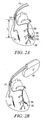
- FIG. 2B shows an electric configuration different from the configuration shown in FIG. 2A :
- electrode 130 is electrically connected to the electrode 140 on the housing 135.
- a first nondefibrillating and nonfibrillation-inducing energy is delivered using the electrode configuration shown in FIG. 2A , where electrode 130 is not electrically connected to electrode 140, and a first resulting electric signal is detected.
- a second nondefibrillating and nonfibrillation-inducing energy is delivered using the electrode configuration shown in FIG. 2B , and a second resulting electric signal is detected.
- the first and second resulting electric signals are each evaluated to determine a corresponding defibrillation threshold energy.
- an electrode configuration having a lower defibrillation threshold energy is selected.
- a defibrillation threshold is determined using two or more resulting electrical signals corresponding to two or more sensor electrode configurations.
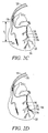
- FIG. 2C shows the same components as FIG. 2A but in a different configuration: Lead 180 and electrodes 185 and 190 are positioned further from the apex 191 of the heart in FIG. 2C than in FIG. 2A .
- a nondefibrillating and nonfibrillation-inducing energy is delivered with the electrodes in the configuration shown in FIG. 2C , and then the lead 180 is inserted further into a blood vessel on the heart until the electrodes are positioned in the configuration shown in FIG.
- Resulting electrical signals are detected using both lead configurations.
- a defibrillation threshold energy is estimated using one or both of the corresponding resulting electrical signals.
- more than two configurations of lead 180 are used.
- resulting electrical signals are detected occasionally, periodically, or continuously as lead 180 is inserted into a vessel or into the heart. Electrical signals at different locations can be used, for example, to assess electric fields at different locations of the left ventricle free wall or the apical region and find the minimum electric field in the target region.
- the resulting electric field in different directions is used to estimate an electric field strength projected in the strongest direction.
- lead 110 is maintained in a fixed position as lead 180 is moved.
- two or more configurations of lead 110 are evaluated using resulting electrical signals detected using electrodes on lead 180.
- FIG. 2D shows a lead 181 and electrodes 191, 192, 193, and 194.
- a portion of the lead including some or all of the electrodes 191, 192, 193, 194 has a nonlinear shape, such as a two-dimensional (2-D) or three-dimensional (3-D) shape, such as a serpentine or helix, respectively.
- the electrodes 191, 192, 193, 194 are all used to detect the first resulting electrical signal.
- the electrodes are located in the left apical region 187, and/or in a left lateral free wall 188.
- a two-part process is used. First, different directional potential gradients associated with the same particular region of the heart are measured. A representative potential gradient is selected for that region (e.g., an average gradient or, more typically, a maximum gradient). Second, after representative potential gradients have been determined for various regions of the heart, then that particular region having a minimum potential gradient is then used to estimate the defibrillation threshold energy. For example, a defibrillation threshold energy is selected to provide a specified electric field between electrodes at a region of the heart having a minimum detected voltage difference, on the assumption that the electrodes represent a region of the heart having a lowest electric field.
- the electrodes used to detect a resulting electrical signal are not necessarily located on the same lead.
- an electrode at a distal end of lead 110 is in combination with an electrode on lead 180 to detect a resulting electrical signal.
- lead 110 is extended around to the left side of the heart and shock electrode 125 is located far enough from the distal end of the lead to allow for useful detection at the distal end.
- the electrodes used to deliver a first nondefibrillating and nonfibrillation-inducing energy are not necessarily on the same lead.
- a defibrillation electrode could be placed on lead 180 or 181, or on another separate lead, and used in combination with electrode 125 or 130 on lead 110 to deliver an energy. It should be noted that when the defibrillation electrode configuration is changed, the target region may also change.
- the leads can extend in, on, or near the heart.
- lead 180 extends near the heart and the electrodes 185, 190 are located outside the target region of the heart.
- the lead 110 can also be positioned so that the electrodes 125, 130 are positioned in, on, or near the heart.
- the electrodes 125, 130 for delivering the nondefibrillating and nonfibrillation-inducing energy are implanted subcutaneously.
- far-field sensing is used to detect the resulting electrical signal.
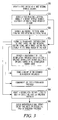
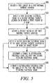
- FIG. 3 is a flowchart that schematically illustrates an example of a method.
- a first energy is delivered at a first internal thoracic location.
- the first energy is nondefibrillating and nonfibrillation-inducing.
- the energy is delivered at a location in and/or near the heart.
- the energy is delivered at a subcutaneous location.
- the energy is non-stimulating.
- the energy is below a patient's pain threshold and/or below a patient's perception threshold.
- the energy is delivered during a specified portion of a cardiac cycle, such as at the end of systole.
- a first resulting electrical signal is detected at a second internal thoracic location in or near a target region of a heart.
- the second internal thoracic location is in the target region.
- the energy is delivered at a location in or near a right region of the heart, such as in the right ventricle or the superior vena cave, and the first resulting electrical signal is detected at a location in or near a left region of the heart, such as in or near a left apical region, and/or in or near a left free lateral wall.
- delivering the energy includes delivering a current and detecting the resulting signal includes detecting a voltage between two electrodes or a current density.
- the first resulting electrical signal is detected through a lead inserted into vasculature on or in the heart, such as vasculature on the left side of the heart.
- the lead is chronically implanted.
- the first resulting electric signal is detected through electrodes in a bipolar lead or multipolar lead, which is optionally located in the left side of the heart.
- the first resulting electrical signal is detected using a guide wire, for example by detecting a voltage difference between an electrode on or of the guide wire and an electrode on the lead.
- a distance between a distal end of the guide wire and an electrode on the lead is estimated using one or more features or markings at the proximal end of the guide wire.
- a position of a marking at the proximal end of the guide wire is recorded and correlated to a position of the distal end of the guide wire.
- the displacement of the distal end of the guide wire is estimated using the marking at the proximal end.
- a lead is temporarily inserted in or around the heart and used to detect resulting electrical heart signals.
- a temporary mapping catheter is inserted in or around the heart.
- the temporary mapping catheter has a multiplicity of electrodes (e.g. 16 or 24 electrodes) that detect resulting electrical signals at locations in or around the heart.
- each electrode is coupled to a separate conductor (e.g. the mapping lead has 16 conductors and 16 electrodes.)
- the lead assembly includes switching capacity (e.g. a multiplexor) so that a resulting electrical signal can be detected using a selected combination of selected electrodes.
- one or more of the resulting electrical signals are used to estimate a defibrillation threshold.
- a defibrillation threshold energy is estimated.
- the defibrillation threshold includes an energy, a voltage, a current and/or a duration.
- the defibrillation threshold energy when delivered to the first internal thoracic location creates an electric field strength in the target region of the heart that meets or exceeds a target electric field strength.
- detecting the resulting signal includes detecting at least one voltage difference between (or among) electrodes, and the estimating includes determining the first electric field strength from the at least one voltage difference and a known configuration of the electrodes.
- the estimating further includes dividing the target defibrillating electric field strength by the first electric field strength to determine a defibrillation scaling factor; and multiplying the first nondefibrillating and nonfibrillation-inducing voltage or current by the defibrillation scaling factor to determine the defibrillation threshold voltage or current.
- estimating the defibrillation threshold energy includes combining fields from three or more electrodes.
- at 325 before a defibrillation threshold is estimated, at least one intrinsic electrical signal is separated from the first resulting electrical signal.
- a post-processing technique is used to subtract out electrical noise.
- a remainder of the detected resulting electrical signal is substantially attributable to the delivery of the energy at the first internal thoracic location.
- the remainder of the resulting electrical signal is used to estimate the defibrillation threshold.
- a blind source separation technique is used to separate at least one intrinsic electric signal from the detected resulting electric signal. Blind source separation techniques are described in copending U.S. patent application no. 10/876,008, filed June 24, 2004 , entitled “Automatic Orientation Determination for ECG Measurements Using Multiple Electrodes,” which is incorporated herein by reference in its entirety.
- a notification is delivered if the estimated defibrillation threshold energy meets or exceeds a specified value or a specified change in value.
- a notification is received by a patient, for example by detecting an audible sound such as a beep.
- a notification is received by a physician, for example by using an external device that communicates with an implanted device wirelessly or otherwise.
- a notification is received by a physician via Internet or other communication over a communications network.
- a notification is delivered if the estimated defibrillation threshold energy meets or exceeds a prescribed defibrillation energy value by 20 %.
- the defibrillation threshold energy is communicated, for example to an external programmer.
- a history of estimated defibrillation threshold energies is stored. Storing a history of estimated defibrillation threshold energies allows for monitoring of a physiological condition, for example. It also allows for monitoring of lead position change or dislodgement.
- a defibrillation threshold can change over time, for example due to myocardial infarction, cardiac remodeling, medication changes, hypertrophy, posture change, or lead dislodgement.
- a defibrillation therapy is adjusted to meet or exceed the defibrillation threshold energy.
- a defibrillation therapy energy meeting or exceeding the defibrillation threshold is delivered.
- the antitachyarrhythmia therapy is delivered through an electrode that was also used to deliver the energy from which the defibrillation threshold was determined.
- the antitachyarrhythmia therapy includes a defibrillation shock delivered at an energy meeting or exceeding the estimated defibrillation threshold.
- an arrhythmia such as a tachyarrhythmia is detected or declared, a nondefibrillating and nonfibrillation-inducing energy is delivered, from which a defibrillation threshold is determined, and then an antitachyarrhythmia therapy having an energy meeting or exceeding the defibrillation threshold is delivered.
- a first energy is delivered at 405 at a first internal thoracic location, a first resulting electrical signal is detected at 410, and a first defibrillation threshold is estimated at 415.
- a second energy is delivered to the first internal thoracic location.
- a second resulting electrical signal is detected.
- a change in defibrillation threshold is determined using the first resulting electrical signal and the second resulting electrical signal.
- a first electric field strength determined from the first resulting electrical signal is compared with a second electric field strength determined from the second resulting electrical signal.
- a second defibrillation threshold energy is estimated for the target region of the heart using the indication of a second electric field strength and the second energy, and the second estimated defibrillation threshold is compared to the first defibrillation threshold.
- a notification is delivered if the second defibrillation threshold energy exceeds the first defibrillation threshold energy by a specified amount.
- a notification is delivered if the second defibrillation threshold exceeds the first defibrillation threshold by a specified amount over a specified amount of time.
- data from at least one other sensor is analyzed.
- the data from the other sensor is used to confirm a change in a defibrillation threshold or characterize a physiologic condition or change. In an example, such information is used to assess whether a notification is delivered or a defibrillation therapy should be altered.
- a notification is delivered or a defibrillation therapy is adjusted if the physiological parameter detected at 435 meets a specified criteria.
- a first nondefibrillating and nonfibrillation-inducing energy is delivered at a first internal thoracic location.
- a first resulting electrical signal is detected at a second internal thoracic location in or near a target region of a heart.
- the first resulting electrical signal is detected using one or more pacing/sensing electrodes.
- the first resulting electrical signal is detected using a guide wire and an intravascular lead.
- a second nondefibrillating and nonfibrillation-inducing energy is detected at the first internal thoracic region.
- a second resulting electrical signal is detected at a third internal thoracic location in or near the target region.
- the second internal thoracic location and third internal thoracic location are locations of electrodes on a lead.
- detecting a first electrical signal includes detecting an electrical signal at a first position on a lead inserted into a coronary vein in the left side of the heart, and detecting a second resulting electrical signal includes detecting an electrical signal through the lead in a second position in a coronary vein in the left side of the heart.
- FIGS. 2A and 2C show a lead at two positions in a coronary vein.
- detecting an electrical signal through a lead in a coronary vein in the left side of the heart includes detecting at least two voltage differences between electrodes on the lead.
- the lead includes a multi-polar lead, as shown in FIG. 2D for example.
- detecting an electrical signal through a lead in a coronary vein in the left side of the heart includes detecting an electrical signal through electrodes on a portion of the lead that extends has a two-dimension path or three-dimensional bias, such as a helical bias, for example.
- positioning electrodes on a portion of a lead that has 3-D bias promotes electric contact with tissue.
- positioning electrodes on a lead that follows a 3-D path allows for positioning of the electrodes at a desired contact location within a vessel, for example to avoid stimulating anatomy such as a nerve.
- both the first resulting electrical signal and the second resulting electrical signal are combined and the combination is used to estimate a defibrillation threshold.
- an average of the first resulting electrical signal and the second resulting electrical signal is used to determine a defibrillation threshold.
- the average is a weighted average.
- multiple measurements e.g. 10's or 100's of resulting electrical signals
- a median or a specified standard deviation from a mean is used to estimate a defibrillation threshold.
- space vector synthesis is used to estimate a defibrillation threshold.
- Blind source separation may also be used to estimate a defibrillation threshold.
- the smaller of the first and second resulting electrical signals is used to determine a defibrillation threshold.
- a resulting electrical signal is detected at various locations in, on, or near the heart to identify a region having a lowest value of a potential gradient. Determining a defibrillation threshold using the lowest potential gradient ensures that the location where the lowest potential gradient was observed will reach a sufficient defibrillating potential gradient when a therapeutic energy is delivered.
- a nondefibrillating and nonfibrillation-inducing energy is delivered to a thorax using a first electrode configuration.
- the energy is delivered in, on, or near a heart.
- a first resulting electrical signal is detected at an internal thoracic location in or near a target region of a heart.
- a second nondefibrillating and nonfibrillation-inducing energy is delivered to the thorax using a second electrode configuration.
- the second electrode configuration is physically and/or electrically different from the first electrode configuration.
- the first and second energies are delivered using the same electrodes, but the electrode's position and/or orientation of the electrodes during delivery of the second energy differs from the position and/or orientation of the electrodes during delivery of the first energy.
- the first energy and second energy optionally have the same magnitude.
- a second resulting electrical signal is detected at the internal thoracic location.
- an electrode configuration that produces a smaller defibrillation threshold is selected for delivery of an antitachyarrhythmia therapy.
- selecting a configuration with a lower defibrillation threshold increases the longevity of a device, because less battery energy is used to deliver a therapy.
- three or more electrode configurations or combinations of electrodes are compared.
- a defibrillation threshold is estimated using at least one of the first and second resulting electrode signals.
- the first and second energy are the same magnitude (e.g. same charged capacitor voltage or same number of Joules), and the defibrillation threshold is estimated for the electrode configuration that yields a larger resulting signal.
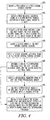
- FIGS. 3 , 4 , 5 , and 6 While various operations in FIGS. 3 , 4 , 5 , and 6 are shown as alternatives, it is understood that various operations can be performed in combination with other operations.
Claims (14)
- Système comprenant :un module d'énergie (150) adapté pour délivrer une énergie n'induisant pas de stimulation, de défibrillation ni de fibrillation, utilisant au moins une première électrode (125) configurée pour être positionnée au niveau d'un premier emplacement thoracique interne, au moins partiellement à l'intérieur d'une chambre cardiaque du côté droit d'un coeur ;un module de signal de réponse (155) adapté pour détecter un signal résultant en utilisant au moins une deuxième électrode (185) et une troisième électrode (190), les deuxième et troisième électrodes (185, 190) étant configurées pour être positionnées au niveau d'un deuxième emplacement thoracique interne dans ou à proximité d'une région cible du côté gauche d'un coeur (), et dans lequel les deuxième et troisième électrodes sont formées et configurées pour être implantées à l'intérieur d'un vaisseau coronaire dans ou sur une région apicale gauche du coeur (187) ou d'une paroi latérale libre de ventricule gauche (188), et le signal sensible provenant de la distribution de l'énergie et fournissant une indication d'une résistance de champ électrique dans le deuxième emplacement thoracique interne () ; etun contrôleur (160) couplé de manière communicative au module d'énergie (150) et au module de signal de réponse (155), caractérisé en ce que le contrôleur (160) est adapté pour déterminer la résistance de champ électrique au niveau du deuxième emplacement par rapport à une différence de tension entre les et troisième électrodes et une configuration connue de ces électrodes est pour estimer un seuil de défibrillation en divisant une résistance de champ électrique cible par la résistance de champ électrique au niveau du deuxième emplacement afin de déterminer un facteur d'échelle de défibrillation et en multipliant le premier courant ou tension n'induisant pas de stimulation, de défibrillation ni de fibrillation par le facteur d'échelle de défibrillation afin de déterminer la tension ou courant de seuil de défibrillation.
- Système (100) selon la revendication 1, comprenant en outre la première électrode (125), la deuxième électrode (185) et dans lequel le module de signal de réponse (155) est adapté pour détecter une tension entre la deuxième électrode (185) et une troisième électrode (190) au niveau d'un emplacement dans ou du côté gauche du coeur à une distance connue ou estimée de la deuxième électrode (185).
- Système (100) selon la revendication 1, comprenant en outre un fil (180) pouvant être positionné dans un vaisseau coronaire dans le côté gauche du coeur, dans lequel le module de signal de réponse (155) est adapté pour détecter des signaux de réponse résultants à plusieurs emplacements respectifs dans le vaisseau coronaire, et le contrôleur (160) est adapté pour estimer un seuil de défibrillation en utilisant les signaux de réponse détectés par le module de signal de réponse (155).
- Système (100) selon la revendication 1, dans lequel le contrôleur (160) est adapté pour comparer un signal résultant détecté avec un signal résultant détecté au préalable afin de détecter au moins l'un parmi un changement du signal résultant indiquant un changement de seuil de défibrillation, un changement physiologique, un changement de posture ou un délogement de fil (180).
- Système (100) selon la revendication 1, dans lequel le contrôleur (160) est adapté pour comparer un seuil de défibrillation estimé à un seuil de défibrillation estimé au préalable afin de détecter un changement du seuil de défibrillation.
- Système (100) selon la revendication 6, dans lequel le contrôleur (160) est adapté pour délivrer une notification si un seuil de défibrillation modifié est détecté.
- Système (100) selon la revendication 6, dans lequel le contrôleur (160) est adapté pour augmenter un niveau d'énergie d'une thérapie anti-tachyarythmie si un seuil de défibrillation augmenté est détecté.
- Système (100) selon la revendication 1, dans lequel le contrôleur (160) est configuré pour modifier une configuration d'électrode, estimer un deuxième seuil de défibrillation pour au moins une deuxième configuration d'électrode, comparer les seuils de défibrillation estimés pour au moins deux configurations d'électrode, et sélectionner une configuration d'électrode de défibrillation en utilisant les seuils de défibrillation estimés.
- Système (100) selon la revendication 1, comprenant en outre un circuit de détection de signal cardiaque intrinsèque, le contrôleur étant couplé de manière communicative au circuit de détection de signal cardiaque intrinsèque et adapté pour délivrer une énergie n'induisant pas de défibrillation ni de fibrillation à une partie spécifiée d'un cycle cardiaque.
- Système (100) selon la revendication 1, comprenant en outre un circuit de détection de respiration, le contrôleur (160) étant couplé de manière communicative au circuit de détection de respiration et adapté pour délivrer l'énergie n'induisant pas de défibrillation ni de fibrillation au niveau d'une partie spécifiée d'un cycle respiratoire.
- Système (100) selon la revendication 1, comprenant en outre un circuit de détection de cardiaque intrinsèque, le contrôleur (160) étant couplé de communicative au circuit de détection de signal cardiaque intrinsèque et adapté pour détecter le signal électrique résultant au niveau d'une partie spécifiée d'un cycle cardiaque ou d'un cycle respiratoire.
- Système selon la revendication 1, comprenant en outre la première électrode (125) et la deuxième électrode (185).
- Procédé comprenant les étapes consistant à :délivrer une première énergie n'induisant pas de stimulation, de défibrillation ni de fibrillation au niveau d'un premier emplacement thoracique interne qui est au moins partiellement à l'intérieur d'une chambre cardiaque du côté droit d'un coeur en utilisant au moins une première électrode ;détecter un premier signal électrique résultant en utilisant au moins une deuxième et une troisième électrode qui ont déjà été implantées au niveau d'un deuxième emplacement thoracique interne dans ou à proximité d'une région cible d'un coeur, dans lequel le deuxième emplacement thoracique interne est à l'intérieur d'un vaisseau coronaire dans ou sur une région apicale gauche du coeur ou d'une paroi libre latérale ventriculaire gauche, le premier signal électrique résultant fournissant une indication d'une première résistance de champ électrique au niveau du deuxième emplacement thoracique interne ; etdéterminer la résistance de champ électrique au niveau d'un deuxième emplacement par rapport à la différence de tension entre les deuxième et troisième électrodes et une configuration connue de ces électrodes et pour estimer un seuil de défibrillation en divisant une résistance de champ électrique cible par la résistance de champ électrique au niveau du deuxième emplacement afin de déterminer un facteur d'échelle de défibrillation et en multipliant le premier courant ou tension n'induisant pas de stimulation, de défibrillation ni de fibrillation par le facteur d'échelle de défibrillation afin de déterminer le courant ou tension de seuil de défibrillation.
- Procédé comprenant les étapes consistant à :délivrer une première énergie n'induisant pas de stimulation, de défibrillation ni de fibrillation à un thorax en utilisant une première configuration de défibrillation au niveau d'un emplacement thoracique interne qui est au moins partiellement à l'intérieur d'une chambre cardiaque du côté droit d'un coeur ;detecter un premier signal électrique; résultant en utilisant au moins une deuxième et une troisième électrode qui ont déjà été implantées au niveau du deuxième emplacement thoracique interne à l'intérieur d'un vaisseau coronaire dans ou sur une région apicale gauche du coeur ou une paroi libre latérale ventriculaire gauche dans ou à proximité d'une région cible d'un coeur, le premier signal électrique résultant fournissant une indication d'une première résistance de champ électrique au niveau du deuxième emplacement thoracique interne ;délivrer une deuxième énergie n'induisant pas de stimulation, de défibrillation ni de fibrillation au thorax en utilisant une deuxième configuration de défibrillation au niveau d'un emplacement thoracique interne qui est au moins partiellement à l'intérieur d'une chambre cardiaque du côté droit d'un coeur ;détecter un deuxième signal électrique résultant au niveau d'un emplacement thoracique interne à l'intérieur d'un vaisseau coronaire dans ou sur une région apicale gauche du coeur ou d'une paroi libre latérale ventriculaire gauche en utilisant les au moins deuxième et troisième électrodes, le deuxième signal électrique résultant fournissant une indication d'une deuxième résistance de champ électrique au niveau du deuxième emplacement thoracique interne du coeur pendant la distribution de l'énergie n'induisant pas de défibrillation ni de fibrillation en utilisant la deuxième configuration de défibrillation ; etdéterminer pour les deux configurations d'électrode, la résistance de champ électrique au niveau d'un deuxième emplacement par rapport à la différence de tension entre les deuxième et troisième électrodes et une configuration connue de ces électrodes et pour estimer le seuil de défibrillation pour les deux configurations d'électrode en divisant une résistance de champ électrique cible respectivement par les première et deuxième résistances de champ électrique au niveau du deuxième emplacement afin de déterminer un facteur d'échelle de défibrillation et en multipliant le premier courant ou tension n'induisant pas de stimulation, de défibrillation ni de fibrillation par le facteur d'échelle de défibrillation afin de déterminer le courant ou tension de seuil de défibrillation.
Applications Claiming Priority (2)
| Application Number | Priority Date | Filing Date | Title |
|---|---|---|---|
| US11/208,923 US7711425B2 (en) | 2005-08-22 | 2005-08-22 | Defibrillation threshold prediction methods and systems |
| PCT/US2006/030829 WO2007024471A1 (fr) | 2005-08-22 | 2006-08-09 | Procedes et systemes de prevision de valeur seuil de defibrillation |
Publications (2)
| Publication Number | Publication Date |
|---|---|
| EP1928548A1 EP1928548A1 (fr) | 2008-06-11 |
| EP1928548B1 true EP1928548B1 (fr) | 2012-02-15 |
Family
ID=37441107
Family Applications (1)
| Application Number | Title | Priority Date | Filing Date |
|---|---|---|---|
| EP06789564A Not-in-force EP1928548B1 (fr) | 2005-08-22 | 2006-08-09 | Procedes et systemes de prevision de valeur seuil de defibrillation |
Country Status (5)
| Country | Link |
|---|---|
| US (1) | US7711425B2 (fr) |
| EP (1) | EP1928548B1 (fr) |
| JP (1) | JP5015933B2 (fr) |
| AT (1) | ATE545447T1 (fr) |
| WO (1) | WO2007024471A1 (fr) |
Cited By (1)
| Publication number | Priority date | Publication date | Assignee | Title |
|---|---|---|---|---|
| US8768460B2 (en) | 2007-04-03 | 2014-07-01 | Cardiac Pacemakers, Inc. | Pain free defibrillation threshold estimation |
Families Citing this family (13)
| Publication number | Priority date | Publication date | Assignee | Title |
|---|---|---|---|---|
| US6751502B2 (en) | 2001-03-14 | 2004-06-15 | Cardiac Pacemakers, Inc. | Cardiac rhythm management system with defibrillation threshold prediction |
| WO2005074566A2 (fr) * | 2004-02-03 | 2005-08-18 | Cornell Research Foundation, Inc. | Procede pour identifier des strategies pour traiter ou prevenir la fibrillation ventriculaire et la tachycardie ventriculaire |
| US7711425B2 (en) | 2005-08-22 | 2010-05-04 | Cardiac Pacemakers, Inc. | Defibrillation threshold prediction methods and systems |
| WO2009108502A1 (fr) * | 2008-02-27 | 2009-09-03 | Avi Livnat | Défibrillation atriale utilisant un système de défibrillation implantable |
| EP2608845A2 (fr) * | 2010-08-23 | 2013-07-03 | Rafael Development Corporation Ltd. | Synchronisation d'administration d'impulsions de défibrillation avec cycle respiratoire |
| US9789307B2 (en) | 2011-04-29 | 2017-10-17 | Medtronic, Inc. | Dual prophylactic and abortive electrical stimulation |
| US9649494B2 (en) | 2011-04-29 | 2017-05-16 | Medtronic, Inc. | Electrical stimulation therapy based on head position |
| US10448889B2 (en) | 2011-04-29 | 2019-10-22 | Medtronic, Inc. | Determining nerve location relative to electrodes |
| US11097109B2 (en) | 2014-11-24 | 2021-08-24 | AtaCor Medical, Inc. | Cardiac pacing sensing and control |
| US11452874B2 (en) | 2020-02-03 | 2022-09-27 | Medtronic, Inc. | Shape control for electrical stimulation therapy |
| US11554264B2 (en) | 2020-04-24 | 2023-01-17 | Medtronic, Inc. | Electrode position detection |
| US11666771B2 (en) * | 2020-05-29 | 2023-06-06 | AtaCor Medical, Inc. | Implantable electrical leads and associated delivery systems |
| WO2023110388A1 (fr) * | 2021-12-14 | 2023-06-22 | Biotronik Se & Co. Kg | Dispositif de défibrillateur automatique implantable non transveineux pour émettre une impulsion de fibrillation |
Family Cites Families (24)
| Publication number | Priority date | Publication date | Assignee | Title |
|---|---|---|---|---|
| US5105809A (en) * | 1990-08-23 | 1992-04-21 | Cardiac Pacemakers, Inc. | System and method for evaluating lead defibrillation requirements of an implanted device without repeated fibrillation induction |
| DE59209466D1 (de) * | 1992-06-17 | 1998-09-24 | Pacesetter Ab | Defibrillator/Kardiovertierer |
| US5662687A (en) * | 1992-09-16 | 1997-09-02 | Pacesetter Ab | Implantable heart defibrillator |
| US5346506A (en) * | 1992-11-10 | 1994-09-13 | Mower Morton M | Method for establishing defibrillation threshold for a cardiac defibrillator |
| US5318597A (en) * | 1993-03-15 | 1994-06-07 | Cardiac Pacemakers, Inc. | Rate adaptive cardiac rhythm management device control algorithm using trans-thoracic ventilation |
| US5531770A (en) * | 1993-09-03 | 1996-07-02 | Angeion Corporation | Device and method for determining defibrillation thresholds |
| US5540724A (en) * | 1995-02-03 | 1996-07-30 | Intermedics, Inc. | Cardiac cardioverter/defibrillator with in vivo impedance estimation |
| US5683431A (en) * | 1996-03-27 | 1997-11-04 | Medtronic, Inc. | Verification of capture by sensing evoked response across cardioversion electrodes |
| WO1998040122A1 (fr) * | 1997-03-14 | 1998-09-17 | University Of Alabama At Birmingham Research Foundation | Methode et appareil de traitement de l'arythmie cardiaque |
| WO1998047563A1 (fr) * | 1997-04-18 | 1998-10-29 | Physio-Control Manufacturing Corporation | Defibrillateur et procede de defibrillation |
| US5925067A (en) * | 1997-12-11 | 1999-07-20 | Pacesetter, Inc. | Automatic capture detection during non-invasive programmed stimulation of a patient's heart |
| US6076015A (en) * | 1998-02-27 | 2000-06-13 | Cardiac Pacemakers, Inc. | Rate adaptive cardiac rhythm management device using transthoracic impedance |
| US6169923B1 (en) * | 1999-04-23 | 2001-01-02 | Pacesetter, Inc. | Implantable cardioverter-defibrillator with automatic arrhythmia detection criteria adjustment |
| US6353761B1 (en) * | 1999-08-20 | 2002-03-05 | Cardiac Pacemakers, Inc. | Cardiac rhythm management system with user interface for threshold test |
| AU2001249877A1 (en) * | 2000-04-13 | 2001-10-30 | Uab Research Foundation | Inter-atrial septum electrode for atrial defibrillation |
| US20020002389A1 (en) * | 2000-05-15 | 2002-01-03 | Kerry Bradley | Cardiac stimulation devices and methods for measuring impedances associated with the left side of the heart |
| US6363281B1 (en) * | 2000-05-16 | 2002-03-26 | Cardiac Pacemakers, Inc. | Cardiac rhythm management system and method |
| US6751502B2 (en) * | 2001-03-14 | 2004-06-15 | Cardiac Pacemakers, Inc. | Cardiac rhythm management system with defibrillation threshold prediction |
| US6625487B2 (en) * | 2001-07-17 | 2003-09-23 | Koninklijke Philips Electronics N.V. | Bioelectrical impedance ECG measurement and defibrillator implementing same |
| US6904314B1 (en) * | 2002-04-09 | 2005-06-07 | Pacesetter, Inc. | Automatic defibrillation threshold tracking |
| US6675042B2 (en) * | 2002-04-15 | 2004-01-06 | Charles D. Swerdlow | Defibrillation shock strength determination technology |
| US6978178B2 (en) * | 2002-04-30 | 2005-12-20 | Medtronic, Inc. | Method and apparatus for selecting an optimal electrode configuration of a medical electrical lead having a multiple electrode array |
| US7711425B2 (en) | 2005-08-22 | 2010-05-04 | Cardiac Pacemakers, Inc. | Defibrillation threshold prediction methods and systems |
| US7890167B2 (en) * | 2007-04-03 | 2011-02-15 | Cardiac Pacemakers, Inc. | Pain free defibrillation threshold estimation |
-
2005
- 2005-08-22 US US11/208,923 patent/US7711425B2/en not_active Expired - Fee Related
-
2006
- 2006-08-09 JP JP2008527952A patent/JP5015933B2/ja not_active Expired - Fee Related
- 2006-08-09 WO PCT/US2006/030829 patent/WO2007024471A1/fr active Application Filing
- 2006-08-09 AT AT06789564T patent/ATE545447T1/de active
- 2006-08-09 EP EP06789564A patent/EP1928548B1/fr not_active Not-in-force
Cited By (1)
| Publication number | Priority date | Publication date | Assignee | Title |
|---|---|---|---|---|
| US8768460B2 (en) | 2007-04-03 | 2014-07-01 | Cardiac Pacemakers, Inc. | Pain free defibrillation threshold estimation |
Also Published As
| Publication number | Publication date |
|---|---|
| JP2009504361A (ja) | 2009-02-05 |
| US7711425B2 (en) | 2010-05-04 |
| ATE545447T1 (de) | 2012-03-15 |
| WO2007024471A1 (fr) | 2007-03-01 |
| JP5015933B2 (ja) | 2012-09-05 |
| EP1928548A1 (fr) | 2008-06-11 |
| US20070043395A1 (en) | 2007-02-22 |
Similar Documents
| Publication | Publication Date | Title |
|---|---|---|
| EP1928548B1 (fr) | Procedes et systemes de prevision de valeur seuil de defibrillation | |
| US8036744B2 (en) | Cardiac rhythm management system with defibrillation threshold prediction | |
| CN107073275B (zh) | 具有触发的消隐周期的医疗设备 | |
| JP6659578B2 (ja) | 医療装置での感知ベクトル構成を選択するための方法及び機器 | |
| US7047071B2 (en) | Patient stratification for implantable subcutaneous cardiac monitoring and therapy | |
| US10170944B2 (en) | Rechargeable impantable cardioverter defibrillator | |
| US7570997B2 (en) | Subcutaneous cardiac rhythm management with asystole prevention therapy | |
| US7392081B2 (en) | Subcutaneous cardiac stimulator employing post-shock transthoracic asystole prevention pacing | |
| US20150094783A1 (en) | Method for detecting and treating ventricular arrhythmia | |
| EP0661078A2 (fr) | Conducteur pour défibrillation cardiaque avec des électrodes pour détection atriale et pour défibrillation | |
| US20040230230A1 (en) | Methods and systems involving subcutaneous electrode positioning relative to a heart | |
| US8000786B2 (en) | Multiple pulse defibrillation for subcutaneous implantable cardiac devices | |
| US20040220628A1 (en) | Subcutaneous defibrillation timing correlated with induced skeletal muscle contraction | |
| JP2005523786A (ja) | 皮下電極を有する植込み型自動除細動器 | |
| US7389138B2 (en) | Electrode placement determination for subcutaneous cardiac monitoring and therapy | |
| US20220362568A1 (en) | Inhibition of onset of cardiac tachyarrhythmia with intercostal nerve stimulation |
Legal Events
| Date | Code | Title | Description |
|---|---|---|---|
| PUAI | Public reference made under article 153(3) epc to a published international application that has entered the european phase |
Free format text: ORIGINAL CODE: 0009012 |
|
| 17P | Request for examination filed |
Effective date: 20080319 |
|
| AK | Designated contracting states |
Kind code of ref document: A1 Designated state(s): AT BE BG CH CY CZ DE DK EE ES FI FR GB GR HU IE IS IT LI LT LU LV MC NL PL PT RO SE SI SK TR |
|
| 17Q | First examination report despatched |
Effective date: 20080715 |
|
| GRAP | Despatch of communication of intention to grant a patent |
Free format text: ORIGINAL CODE: EPIDOSNIGR1 |
|
| DAX | Request for extension of the european patent (deleted) | ||
| RIN1 | Information on inventor provided before grant (corrected) |
Inventor name: ZHANG, YI Inventor name: STAHMANN, JEFFREY, E. Inventor name: BOCEK, JOSEPH, M. Inventor name: SWEENEY, ROBERT, J. Inventor name: WEI, XUAN Inventor name: MEYER, SCOTT, A. |
|
| GRAS | Grant fee paid |
Free format text: ORIGINAL CODE: EPIDOSNIGR3 |
|
| GRAA | (expected) grant |
Free format text: ORIGINAL CODE: 0009210 |
|
| AK | Designated contracting states |
Kind code of ref document: B1 Designated state(s): AT BE BG CH CY CZ DE DK EE ES FI FR GB GR HU IE IS IT LI LT LU LV MC NL PL PT RO SE SI SK TR |
|
| REG | Reference to a national code |
Ref country code: GB Ref legal event code: FG4D Ref country code: CH Ref legal event code: EP |
|
| REG | Reference to a national code |
Ref country code: IE Ref legal event code: FG4D |
|
| REG | Reference to a national code |
Ref country code: AT Ref legal event code: REF Ref document number: 545447 Country of ref document: AT Kind code of ref document: T Effective date: 20120315 |
|
| REG | Reference to a national code |
Ref country code: DE Ref legal event code: R096 Ref document number: 602006027657 Country of ref document: DE Effective date: 20120412 |
|
| REG | Reference to a national code |
Ref country code: NL Ref legal event code: VDEP Effective date: 20120215 |
|
| LTIE | Lt: invalidation of european patent or patent extension |
Effective date: 20120215 |
|
| PG25 | Lapsed in a contracting state [announced via postgrant information from national office to epo] |
Ref country code: LT Free format text: LAPSE BECAUSE OF FAILURE TO SUBMIT A TRANSLATION OF THE DESCRIPTION OR TO PAY THE FEE WITHIN THE PRESCRIBED TIME-LIMIT Effective date: 20120215 Ref country code: NL Free format text: LAPSE BECAUSE OF FAILURE TO SUBMIT A TRANSLATION OF THE DESCRIPTION OR TO PAY THE FEE WITHIN THE PRESCRIBED TIME-LIMIT Effective date: 20120215 Ref country code: IS Free format text: LAPSE BECAUSE OF FAILURE TO SUBMIT A TRANSLATION OF THE DESCRIPTION OR TO PAY THE FEE WITHIN THE PRESCRIBED TIME-LIMIT Effective date: 20120615 |
|
| PG25 | Lapsed in a contracting state [announced via postgrant information from national office to epo] |
Ref country code: PT Free format text: LAPSE BECAUSE OF FAILURE TO SUBMIT A TRANSLATION OF THE DESCRIPTION OR TO PAY THE FEE WITHIN THE PRESCRIBED TIME-LIMIT Effective date: 20120615 Ref country code: LV Free format text: LAPSE BECAUSE OF FAILURE TO SUBMIT A TRANSLATION OF THE DESCRIPTION OR TO PAY THE FEE WITHIN THE PRESCRIBED TIME-LIMIT Effective date: 20120215 Ref country code: FI Free format text: LAPSE BECAUSE OF FAILURE TO SUBMIT A TRANSLATION OF THE DESCRIPTION OR TO PAY THE FEE WITHIN THE PRESCRIBED TIME-LIMIT Effective date: 20120215 Ref country code: GR Free format text: LAPSE BECAUSE OF FAILURE TO SUBMIT A TRANSLATION OF THE DESCRIPTION OR TO PAY THE FEE WITHIN THE PRESCRIBED TIME-LIMIT Effective date: 20120516 Ref country code: BE Free format text: LAPSE BECAUSE OF FAILURE TO SUBMIT A TRANSLATION OF THE DESCRIPTION OR TO PAY THE FEE WITHIN THE PRESCRIBED TIME-LIMIT Effective date: 20120215 Ref country code: PL Free format text: LAPSE BECAUSE OF FAILURE TO SUBMIT A TRANSLATION OF THE DESCRIPTION OR TO PAY THE FEE WITHIN THE PRESCRIBED TIME-LIMIT Effective date: 20120215 |
|
| REG | Reference to a national code |
Ref country code: AT Ref legal event code: MK05 Ref document number: 545447 Country of ref document: AT Kind code of ref document: T Effective date: 20120215 |
|
| PG25 | Lapsed in a contracting state [announced via postgrant information from national office to epo] |
Ref country code: CY Free format text: LAPSE BECAUSE OF FAILURE TO SUBMIT A TRANSLATION OF THE DESCRIPTION OR TO PAY THE FEE WITHIN THE PRESCRIBED TIME-LIMIT Effective date: 20120215 |
|
| PG25 | Lapsed in a contracting state [announced via postgrant information from national office to epo] |
Ref country code: RO Free format text: LAPSE BECAUSE OF FAILURE TO SUBMIT A TRANSLATION OF THE DESCRIPTION OR TO PAY THE FEE WITHIN THE PRESCRIBED TIME-LIMIT Effective date: 20120215 Ref country code: SE Free format text: LAPSE BECAUSE OF FAILURE TO SUBMIT A TRANSLATION OF THE DESCRIPTION OR TO PAY THE FEE WITHIN THE PRESCRIBED TIME-LIMIT Effective date: 20120215 Ref country code: DK Free format text: LAPSE BECAUSE OF FAILURE TO SUBMIT A TRANSLATION OF THE DESCRIPTION OR TO PAY THE FEE WITHIN THE PRESCRIBED TIME-LIMIT Effective date: 20120215 Ref country code: EE Free format text: LAPSE BECAUSE OF FAILURE TO SUBMIT A TRANSLATION OF THE DESCRIPTION OR TO PAY THE FEE WITHIN THE PRESCRIBED TIME-LIMIT Effective date: 20120215 Ref country code: CZ Free format text: LAPSE BECAUSE OF FAILURE TO SUBMIT A TRANSLATION OF THE DESCRIPTION OR TO PAY THE FEE WITHIN THE PRESCRIBED TIME-LIMIT Effective date: 20120215 Ref country code: SI Free format text: LAPSE BECAUSE OF FAILURE TO SUBMIT A TRANSLATION OF THE DESCRIPTION OR TO PAY THE FEE WITHIN THE PRESCRIBED TIME-LIMIT Effective date: 20120215 |
|
| PG25 | Lapsed in a contracting state [announced via postgrant information from national office to epo] |
Ref country code: SK Free format text: LAPSE BECAUSE OF FAILURE TO SUBMIT A TRANSLATION OF THE DESCRIPTION OR TO PAY THE FEE WITHIN THE PRESCRIBED TIME-LIMIT Effective date: 20120215 |
|
| PLBE | No opposition filed within time limit |
Free format text: ORIGINAL CODE: 0009261 |
|
| STAA | Information on the status of an ep patent application or granted ep patent |
Free format text: STATUS: NO OPPOSITION FILED WITHIN TIME LIMIT |
|
| 26N | No opposition filed |
Effective date: 20121116 |
|
| PG25 | Lapsed in a contracting state [announced via postgrant information from national office to epo] |
Ref country code: AT Free format text: LAPSE BECAUSE OF FAILURE TO SUBMIT A TRANSLATION OF THE DESCRIPTION OR TO PAY THE FEE WITHIN THE PRESCRIBED TIME-LIMIT Effective date: 20120215 |
|
| REG | Reference to a national code |
Ref country code: DE Ref legal event code: R097 Ref document number: 602006027657 Country of ref document: DE Effective date: 20121116 |
|
| REG | Reference to a national code |
Ref country code: CH Ref legal event code: PL |
|
| PG25 | Lapsed in a contracting state [announced via postgrant information from national office to epo] |
Ref country code: MC Free format text: LAPSE BECAUSE OF NON-PAYMENT OF DUE FEES Effective date: 20120831 |
|
| GBPC | Gb: european patent ceased through non-payment of renewal fee |
Effective date: 20120809 |
|
| PG25 | Lapsed in a contracting state [announced via postgrant information from national office to epo] |
Ref country code: CH Free format text: LAPSE BECAUSE OF NON-PAYMENT OF DUE FEES Effective date: 20120831 Ref country code: ES Free format text: LAPSE BECAUSE OF FAILURE TO SUBMIT A TRANSLATION OF THE DESCRIPTION OR TO PAY THE FEE WITHIN THE PRESCRIBED TIME-LIMIT Effective date: 20120526 Ref country code: LI Free format text: LAPSE BECAUSE OF NON-PAYMENT OF DUE FEES Effective date: 20120831 |
|
| REG | Reference to a national code |
Ref country code: FR Ref legal event code: ST Effective date: 20130430 |
|
| REG | Reference to a national code |
Ref country code: IE Ref legal event code: MM4A |
|
| PG25 | Lapsed in a contracting state [announced via postgrant information from national office to epo] |
Ref country code: IE Free format text: LAPSE BECAUSE OF NON-PAYMENT OF DUE FEES Effective date: 20120809 Ref country code: GB Free format text: LAPSE BECAUSE OF NON-PAYMENT OF DUE FEES Effective date: 20120809 Ref country code: BG Free format text: LAPSE BECAUSE OF FAILURE TO SUBMIT A TRANSLATION OF THE DESCRIPTION OR TO PAY THE FEE WITHIN THE PRESCRIBED TIME-LIMIT Effective date: 20120515 |
|
| PG25 | Lapsed in a contracting state [announced via postgrant information from national office to epo] |
Ref country code: FR Free format text: LAPSE BECAUSE OF NON-PAYMENT OF DUE FEES Effective date: 20120831 |
|
| PG25 | Lapsed in a contracting state [announced via postgrant information from national office to epo] |
Ref country code: TR Free format text: LAPSE BECAUSE OF FAILURE TO SUBMIT A TRANSLATION OF THE DESCRIPTION OR TO PAY THE FEE WITHIN THE PRESCRIBED TIME-LIMIT Effective date: 20120215 |
|
| PG25 | Lapsed in a contracting state [announced via postgrant information from national office to epo] |
Ref country code: LU Free format text: LAPSE BECAUSE OF NON-PAYMENT OF DUE FEES Effective date: 20120809 |
|
| PG25 | Lapsed in a contracting state [announced via postgrant information from national office to epo] |
Ref country code: HU Free format text: LAPSE BECAUSE OF FAILURE TO SUBMIT A TRANSLATION OF THE DESCRIPTION OR TO PAY THE FEE WITHIN THE PRESCRIBED TIME-LIMIT Effective date: 20060809 |
|
| REG | Reference to a national code |
Ref country code: DE Ref legal event code: R082 Ref document number: 602006027657 Country of ref document: DE Representative=s name: PFENNING, MEINIG & PARTNER MBB PATENTANWAELTE, DE Ref country code: DE Ref legal event code: R082 Ref document number: 602006027657 Country of ref document: DE Representative=s name: PFENNING MEINIG & PARTNER GBR, DE |
|
| PGFP | Annual fee paid to national office [announced via postgrant information from national office to epo] |
Ref country code: IT Payment date: 20190821 Year of fee payment: 14 Ref country code: DE Payment date: 20190730 Year of fee payment: 14 |
|
| REG | Reference to a national code |
Ref country code: DE Ref legal event code: R119 Ref document number: 602006027657 Country of ref document: DE |
|
| PG25 | Lapsed in a contracting state [announced via postgrant information from national office to epo] |
Ref country code: DE Free format text: LAPSE BECAUSE OF NON-PAYMENT OF DUE FEES Effective date: 20210302 Ref country code: IT Free format text: LAPSE BECAUSE OF NON-PAYMENT OF DUE FEES Effective date: 20200809 |