EP1928173A1 - Television and rib structure - Google Patents
Television and rib structure Download PDFInfo
- Publication number
- EP1928173A1 EP1928173A1 EP07022992A EP07022992A EP1928173A1 EP 1928173 A1 EP1928173 A1 EP 1928173A1 EP 07022992 A EP07022992 A EP 07022992A EP 07022992 A EP07022992 A EP 07022992A EP 1928173 A1 EP1928173 A1 EP 1928173A1
- Authority
- EP
- European Patent Office
- Prior art keywords
- rib
- display panel
- cabinet
- rib portion
- television
- Prior art date
- Legal status (The legal status is an assumption and is not a legal conclusion. Google has not performed a legal analysis and makes no representation as to the accuracy of the status listed.)
- Granted
Links
- 230000035939 shock Effects 0.000 description 11
- 230000003014 reinforcing effect Effects 0.000 description 8
- 239000002184 metal Substances 0.000 description 3
- 229910052751 metal Inorganic materials 0.000 description 3
- 239000011347 resin Substances 0.000 description 3
- 229920005989 resin Polymers 0.000 description 3
- 101000827703 Homo sapiens Polyphosphoinositide phosphatase Proteins 0.000 description 2
- 102100023591 Polyphosphoinositide phosphatase Human genes 0.000 description 2
- 150000002739 metals Chemical class 0.000 description 2
- 230000001105 regulatory effect Effects 0.000 description 2
- 239000012141 concentrate Substances 0.000 description 1
- 230000007547 defect Effects 0.000 description 1
- 230000000694 effects Effects 0.000 description 1
- 239000004973 liquid crystal related substance Substances 0.000 description 1
- 238000004519 manufacturing process Methods 0.000 description 1
- 238000000034 method Methods 0.000 description 1
- 238000000465 moulding Methods 0.000 description 1
- 230000005236 sound signal Effects 0.000 description 1
- 239000000758 substrate Substances 0.000 description 1
Images


Classifications
-
- H—ELECTRICITY
- H04—ELECTRIC COMMUNICATION TECHNIQUE
- H04N—PICTORIAL COMMUNICATION, e.g. TELEVISION
- H04N5/00—Details of television systems
- H04N5/64—Constructional details of receivers, e.g. cabinets or dust covers
- H04N5/645—Mounting of picture tube on chassis or in housing
Definitions
- the present invention relates to a television and a rib structure.
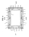
- FIG. 4 illustrates a conventional cabinet for a television.
- the cabinet for a television is composed of a front cabinet and a rear cabinet.
- the front cabinet 1 is generally composed of a front face 2 at the substantial center of which an approximately rectangular opening 3 is formed and side faces 4 extending from the front face 2 to the rear side at the upper, lower, left and right edges of the front face 2.
- the front side of the paper surface is taken to be the rear side of the front cabinet 1 (television) .
- a two-dot chain line indicates where to house a display panel 5 in the front cabinet 1.
- the display panel 5 is fixed to the inside of the front cabinet 1 with the screen of the display panel 5 exposed to the outside from the opening 3.
- a rib 6 is formed around the periphery of the opening 3 on back side (rear side) of the front face 2 in substantially parallel with the upper, lower, left and right straight lines of the opening 3.
- a boss 7 and locating rib 9 are formed at several places on the rib 6 respectively.
- the rib 6, boss 7 and locating rib 9 are uprightly provided from the back side of the front face 2 toward the rear side of the television.
- a screw hole is formed in the center of boss 7.
- the display panel 5 is fixed to the front cabinet 1 such that the screw hole formed in the boss 7 is screwed to a screw hole formed in a sheet metal (not shown) fitted on the periphery of the display panel 5.
- a reinforcing rib 8 for reinforcing the boss 7 extends from the external face of the boss 7.
- the reinforcing rib 8 is also uprightly provided toward the rear side.
- the locating rib 9 with a certain length linearly extends from the wall face of the rib 6 toward the opening 3.
- the display panel 5 is housed in a space surrounded by the leading edge of each locating rib 9.
- the leading edge of each locating rib 9 substantially abuts on and is perpendicular to the side face of the display panel 5.
- a drop test is performed to examine the strength thereof in a process from manufacture to shipment of a television.
- the boss 7 fixing the display panel 5 to the front cabinet 1 is subjected to a large load because the display panel 5 is heavier than other components forming the television. If the boss 7 is cracked or broken at the time of the drop test, the product is rejected.
- the reinforcing rib 8 is formed on the boss 7 to strengthen the boss 7 per se.
- the locating rib 9 is formed to prevent the boss from being broken independently of the number of the reinforcing ribs 8. That is to say, the locating rib 9 substantially prohibits the display panel 5 from moving inside the front cabinet 1 due to the shock of drop to reduce a load exerted on the boss 7.
- the locating rib 9 serves to forcibly prohibit the display panel 5 from moving inside the front cabinet 1 due to the external shock to the television receiver.
- the linear locating rib 9 is apt to directly transmit the external shock to the display panel 5, which resultantly transmits a large shock to the display panel 5 per se.
- the present invention has been made in view of the above problems and has for its purpose to provide a television and a rib structure capable of minimizing an external shock such as drop transmitted to major components such as a display panel inside a cabinet for a product and preventing bosses fixing the major components to the inside of the cabinet from being cracked or broken.
- a rib structure is formed at a predetermined position inside a cabinet and around a display panel housed in the cabinet.
- the rib structure includes a first rib portion and a second rib portion.
- the first rib portion is a substantially linear rib one end of which is opposed to a side face of the display panel.
- the second rib portion is substantially U-shaped (horseshoe shaped) and connected to an other end of the first rib portion at the nearly bottom position of the U-shape. The two ends of the U-shape are connected to a wall face inside the cabinet.
- the second rib portion since the second rib portion is substantially U-shape, the second rib portion absorbs shock exerted from the outside to the cabinet to significantly reduce shock at one end of the first rib portion transmitted to the display panel of which position is regulated in the cabinet.
- the first rib portion may have a shape into which a corner of the one end is cut down obliquely (diagonally) . Such a shape into which the corner of the one end is cut down obliquely enables the display panel to be easily guided to a space when the display panel is housed in the space inside the cabinet surrounded by the rib structure.
- a television comprising a rib structure formed at positions around a display panel housed in a cabinet, the television, wherein the rib structure is integrally formed with a first and a second rib portion uprightly provided toward a rear side of the television on a back side of a front face of the cabinet at a substantial center of which an opening is formed to expose a screen of the display panel to the outside, the first rib portion is substantially linear, one end thereof substantially abuts approximately perpendicularly to a left side face and a right side face of the display panel housed in the cabinet corresponding to a position of the opening and the first rib portion has a shape into which a corner of one end is cut from the rear side toward a front side of the television, and the second rib portion is substantially U-shaped and connected to an other end of the first rib portion at a nearly bottom position of the U-shape and two ends of the U-shape are connected to a wall face of other ribs uprightly provided in substantially parallel with
- FIG. 1 is a rear perspective view schematically illustrating the structure of a television according to the present embodiment.
- a television 110 houses a display panel 50 inside a cabinet composed of a front cabinet 10 and rear cabinet 100.
- the front cabinet 10 and rear cabinet 100 are molded with resin.
- Various types of panels such as a liquid crystal panel or plasma display panel may be used as the display panel 50.
- the cabinet houses known various kinds of circuits and substrates achieving functions of a television such as a tuner circuit, video and audio signal processing circuits, driving circuit for the display panel 50, power supply circuit and loudspeaker as well as the display panel 50, which are not shown in the figure.
- FIG. 2 is a schematic rear view illustrating the inside of the front cabinet 10.
- the front cabinet 10 also includes a front face 20, opening 30 and upper, lower, left and right side faces 40.
- On the back side of the front face 20 are uprightly provided a rib 60 formed around the periphery of the opening 30 in substantially parallel with the upper, lower, left and right straight lines of the opening 30, boss 70 formed at several places on the rib 60 and reinforcing rib 80 formed on the outside face of the boss 70 to reinforce the boss 70.
- the display panel 50 is also fixed to the inside of the front cabinet 10 with the screen of the display panel 50 exposed to the outside from the opening 30.
- a two-dot chain line indicates where to house the display panel 50 in the front cabinet 10.
- sheet metals (not shown) are fixed to the upper and the lower side faces 51 of the display panel 50.
- the display panel 50 is fixed to the front cabinet 10 such that screw holes formed in the sheet metals are screwed to screw holes formed in the bosses 70.
- a locating rib 90 is formed at several places on the rib 60 on the side of the opening 30 of the front cabinet 10.
- the rib structure according to the present invention is realized by the locating rib 90.
- the number of the locating ribs and places where to provide them are optional. In the present embodiment, an example is described where the locating ribs 90 are formed at several places on the wall face of the left and the right rib 60 opposed to the left and the right side faces 51 of the display panel 50.
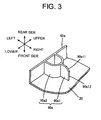
- FIG. 3 is a perspective view illustrating the shape of the locating rib 90.
- the figure illustrates the left rib 60 (rib 60a) out of the upper, lower, left and right ribs 60 and one locating rib 90 (locating rib 90a) out of a plurality of locating ribs 90 uprightly provided from the back side of the front face 20 toward the rear side of the television 110 and integrally formed with the rib 60a.
- the other locating ribs 90 are the same as the locating rib 90a in shape.
- the locating rib 90a is integrally composed of a first rib portion 90al and a second rib portion 90a2.
- the second rib portion 90a2 is of such a shape that a stretch of wall is substantially U-shaped or substantially semicircular (referred to as "substantially U-shaped").
- the two ends of the second rib portion 90a2 (two ends of U-shape) are connected to the wall face of the rib 60a.
- forming the second rib portion 90a2 into the substantially U-shape provides the locating rib 90 with shock absorbability.
- the first rib portion 90al is of substantially linear and extending from the nearly bottom position of the U-shape of the second rib portion 90a2 in the direction approximately perpendicular to the wall of the rib 60a.
- the first rib portion 90a1 is opposed nearly perpendicularly to the left side face 51 of the display panel 50 and the leading edge face 90a12 thereof (corresponding to "one end” in the claim) substantially abuts on the left side face 51.
- the expression “to substantially abut” refers to both cases where the leading edge face 90a12 is brought into contact with the side face 51 and the leading edge face 90a12 is not brought into contact with the side face 51, however, extremely close to the side face 51.
- the display panel 50 is stuck in an area surrounded by the first rib portions of a plurality of the locating ribs 90.
- the locating rib 90 regulating the movement of the display panel 50 fixed to the bosses 70 formed on the back side of the front face 20 of the front cabinet 10 and housed corresponding to the opening 30 is composed of the first rib portion 90a1 that is substantially linear and one end substantially abuts on the side face 51 of the display panel 50 and the second rib portion 90a2 that is approximately U-shaped and connected to the other end of the first rib portion 90al at the nearly bottom position of the U shape and the two ends of the U shape are connected to the wall face of the rib 60 uprightly provided at the back side of the front face 20.
- the second rib portion 90a2 of the locating rib 90 momentarily deforms to absorb shock, enabling significantly reducing a load transmitted to the display panel 50 being precision instrument.
- the locating rib 90 prohibits the display panel 50 from moving inside the front cabinet 10. For this reason, if the television 110 is subjected to the shock, a load given to the boss 70 fixing the display panel 50 to the front cabinet 10 is also reduced to prevent the boss 70 being cracked or broken.
- a slant face 90a11 which slants from the rear to the front side of the television 110 is formed on the corner portion of the rear side of leading edge face 90 a 12 of the first rib portion 90a1. That is to say, the corner of the leading edge face 90a12 is cut diagonally.
- the display panel 50 is inserted into the front cabinet 10 from the rear side thereof. Forming the above slant face 90a11 in advance on the leading edge face 90a12 enables easily housing the display panel 50 in a position surrounded by a plurality of the first rib portions.
Landscapes
- Engineering & Computer Science (AREA)
- Multimedia (AREA)
- Signal Processing (AREA)
- Devices For Indicating Variable Information By Combining Individual Elements (AREA)
Abstract
Description
- The present invention relates to a television and a rib structure.
-
FIG. 4 illustrates a conventional cabinet for a television.
The cabinet for a television is composed of a front cabinet and a rear cabinet. The figure schematically illustrates the inside of the front cabinet 1 as viewed from the rear thereof.
The front cabinet 1 is generally composed of afront face 2 at the substantial center of which an approximatelyrectangular opening 3 is formed andside faces 4 extending from thefront face 2 to the rear side at the upper, lower, left and right edges of thefront face 2. InFIG4 , the front side of the paper surface is taken to be the rear side of the front cabinet 1 (television) . InFIG4 , a two-dot chain line indicates where to house adisplay panel 5 in the front cabinet 1. Thedisplay panel 5 is fixed to the inside of the front cabinet 1 with the screen of thedisplay panel 5 exposed to the outside from theopening 3. - A
rib 6 is formed around the periphery of theopening 3 on back side (rear side) of thefront face 2 in substantially parallel with the upper, lower, left and right straight lines of theopening 3. Aboss 7 and locatingrib 9 are formed at several places on therib 6 respectively. Therib 6,boss 7 and locatingrib 9 are uprightly provided from the back side of thefront face 2 toward the rear side of the television. A screw hole is formed in the center ofboss 7. Thedisplay panel 5 is fixed to the front cabinet 1 such that the screw hole formed in theboss 7 is screwed to a screw hole formed in a sheet metal (not shown) fitted on the periphery of thedisplay panel 5. A reinforcingrib 8 for reinforcing theboss 7 extends from the external face of theboss 7. The reinforcingrib 8 is also uprightly provided toward the rear side.
The locatingrib 9 with a certain length linearly extends from the wall face of therib 6 toward theopening 3. Thedisplay panel 5 is housed in a space surrounded by the leading edge of each locatingrib 9. The leading edge of each locatingrib 9 substantially abuts on and is perpendicular to the side face of thedisplay panel 5. - A drop test is performed to examine the strength thereof in a process from manufacture to shipment of a television. When a product is dropped for the test, the
boss 7 fixing thedisplay panel 5 to the front cabinet 1 is subjected to a large load because thedisplay panel 5 is heavier than other components forming the television. If theboss 7 is cracked or broken at the time of the drop test, the product is rejected. - As described above, therefore, the reinforcing
rib 8 is formed on theboss 7 to strengthen theboss 7 per se. However, it is not easy to concentrate the reinforcingrib 8 on theboss 7 in terms of the structure of a mold used when the front cabinet 1 is molded with resin. Actually, the greater the number of the reinforcingribs 8, the greater difficulty in molding the front cabinet 1, which more easily causes defects in mold around theboss 7 such as a cavity inside resin. For this reason, the locatingrib 9 is formed to prevent the boss from being broken independently of the number of the reinforcingribs 8. That is to say, the locatingrib 9 substantially prohibits thedisplay panel 5 from moving inside the front cabinet 1 due to the shock of drop to reduce a load exerted on theboss 7. - However, a conventional structure has the following problems.
The locatingrib 9 serves to forcibly prohibit thedisplay panel 5 from moving inside the front cabinet 1 due to the external shock to the television receiver. However, the linear locatingrib 9 is apt to directly transmit the external shock to thedisplay panel 5, which resultantly transmits a large shock to thedisplay panel 5 per se. - The present invention has been made in view of the above problems and has for its purpose to provide a television and a rib structure capable of minimizing an external shock such as drop transmitted to major components such as a display panel inside a cabinet for a product and preventing bosses fixing the major components to the inside of the cabinet from being cracked or broken.
- To achieve the above purposes, a rib structure according to the present invention is formed at a predetermined position inside a cabinet and around a display panel housed in the cabinet. Specifically, the rib structure includes a first rib portion and a second rib portion. The first rib portion is a substantially linear rib one end of which is opposed to a side face of the display panel. The second rib portion is substantially U-shaped (horseshoe shaped) and connected to an other end of the first rib portion at the nearly bottom position of the U-shape. The two ends of the U-shape are connected to a wall face inside the cabinet.
That is to say, according to the present invention, since the second rib portion is substantially U-shape, the second rib portion absorbs shock exerted from the outside to the cabinet to significantly reduce shock at one end of the first rib portion transmitted to the display panel of which position is regulated in the cabinet. - The first rib portion may have a shape into which a corner of the one end is cut down obliquely (diagonally) . Such a shape into which the corner of the one end is cut down obliquely enables the display panel to be easily guided to a space when the display panel is housed in the space inside the cabinet surrounded by the rib structure.
- According to the above configuration, a television, comprising a rib structure formed at positions around a display panel housed in a cabinet, the television, wherein the rib structure is integrally formed with a first and a second rib portion uprightly provided toward a rear side of the television on a back side of a front face of the cabinet at a substantial center of which an opening is formed to expose a screen of the display panel to the outside, the first rib portion is substantially linear, one end thereof substantially abuts approximately perpendicularly to a left side face and a right side face of the display panel housed in the cabinet corresponding to a position of the opening and the first rib portion has a shape into which a corner of one end is cut from the rear side toward a front side of the television, and the second rib portion is substantially U-shaped and connected to an other end of the first rib portion at a nearly bottom position of the U-shape and two ends of the U-shape are connected to a wall face of other ribs uprightly provided in substantially parallel with the left side face and the right side face of the display panel and toward the rear side of the television on the back side of the front face of the cabinet.
That is to say, the rib structure achieves the same action and effect also in a concrete product being a television as the foregoing rib structure. The rib structure is applicable to any cabinet as long as a cabinet is used for housing major components such as a display panel. -
-
FIG. 1 is a rear perspective view illustrating one example of a schematic structure of a television receiver; -
FIG. 2 is a rear view illustrating one example of a front cabinet; -
FIG. 3 is a perspective view illustrating one example of a locating rib; and -
FIG. 4 is a rear view illustrating a conventional front cabinet. - One embodiment of the present invention is described below with reference to the drawings.
FIG. 1 is a rear perspective view schematically illustrating the structure of a television according to the present embodiment. Atelevision 110 houses adisplay panel 50 inside a cabinet composed of afront cabinet 10 andrear cabinet 100. Thefront cabinet 10 andrear cabinet 100 are molded with resin. Various types of panels such as a liquid crystal panel or plasma display panel may be used as thedisplay panel 50.
It is to be understood that the cabinet houses known various kinds of circuits and substrates achieving functions of a television such as a tuner circuit, video and audio signal processing circuits, driving circuit for thedisplay panel 50, power supply circuit and loudspeaker as well as thedisplay panel 50, which are not shown in the figure. -
FIG. 2 is a schematic rear view illustrating the inside of thefront cabinet 10. As is the case with the conventional configuration illustrated inFIG. 4 , thefront cabinet 10 also includes afront face 20, opening 30 and upper, lower, left and right side faces 40. On the back side of thefront face 20 are uprightly provided arib 60 formed around the periphery of the opening 30 in substantially parallel with the upper, lower, left and right straight lines of the opening 30,boss 70 formed at several places on the rib 60 and reinforcingrib 80 formed on the outside face of theboss 70 to reinforce theboss 70. As is the case with a conventional display panel, thedisplay panel 50 is also fixed to the inside of thefront cabinet 10 with the screen of thedisplay panel 50 exposed to the outside from theopening 30. InFIG. 2 , as is the case withFIG. 4 , a two-dot chain line indicates where to house thedisplay panel 50 in thefront cabinet 10. - Incidentally, sheet metals (not shown) are fixed to the upper and the lower side faces 51 of the
display panel 50. Thedisplay panel 50 is fixed to thefront cabinet 10 such that screw holes formed in the sheet metals are screwed to screw holes formed in thebosses 70.
A locatingrib 90 is formed at several places on therib 60 on the side of the opening 30 of thefront cabinet 10. The rib structure according to the present invention is realized by the locatingrib 90. The number of the locating ribs and places where to provide them are optional. In the present embodiment, an example is described where the locatingribs 90 are formed at several places on the wall face of the left and theright rib 60 opposed to the left and the right side faces 51 of thedisplay panel 50. -
FIG. 3 is a perspective view illustrating the shape of the locatingrib 90.
The figure illustrates the left rib 60 (rib 60a) out of the upper, lower, left andright ribs 60 and one locating rib 90 (locatingrib 90a) out of a plurality of locatingribs 90 uprightly provided from the back side of thefront face 20 toward the rear side of thetelevision 110 and integrally formed with therib 60a. The other locatingribs 90 are the same as the locatingrib 90a in shape.
The locatingrib 90a is integrally composed of a first rib portion 90al and a second rib portion 90a2. - The second rib portion 90a2 is of such a shape that a stretch of wall is substantially U-shaped or substantially semicircular (referred to as "substantially U-shaped"). The two ends of the second rib portion 90a2 (two ends of U-shape) are connected to the wall face of the
rib 60a. In other words, forming the second rib portion 90a2 into the substantially U-shape provides the locatingrib 90 with shock absorbability.
The first rib portion 90al is of substantially linear and extending from the nearly bottom position of the U-shape of the second rib portion 90a2 in the direction approximately perpendicular to the wall of therib 60a. The first rib portion 90a1 is opposed nearly perpendicularly to theleft side face 51 of thedisplay panel 50 and the leading edge face 90a12 thereof (corresponding to "one end" in the claim) substantially abuts on theleft side face 51. Incidentally, the expression "to substantially abut" refers to both cases where the leading edge face 90a12 is brought into contact with theside face 51 and the leading edge face 90a12 is not brought into contact with theside face 51, however, extremely close to theside face 51. In either case, as illustrated inFIG. 2 , thedisplay panel 50 is stuck in an area surrounded by the first rib portions of a plurality of the locatingribs 90. - According to the present invention, as described above, the locating
rib 90 regulating the movement of thedisplay panel 50 fixed to thebosses 70 formed on the back side of thefront face 20 of thefront cabinet 10 and housed corresponding to theopening 30 is composed of the first rib portion 90a1 that is substantially linear and one end substantially abuts on theside face 51 of thedisplay panel 50 and the second rib portion 90a2 that is approximately U-shaped and connected to the other end of the first rib portion 90al at the nearly bottom position of the U shape and the two ends of the U shape are connected to the wall face of therib 60 uprightly provided at the back side of thefront face 20.
For this reason, if thetelevision 110 is subjected to shock from the outside at the time of performing a drop test or the like, the second rib portion 90a2 of the locatingrib 90 momentarily deforms to absorb shock, enabling significantly reducing a load transmitted to thedisplay panel 50 being precision instrument. - The locating
rib 90 prohibits thedisplay panel 50 from moving inside thefront cabinet 10. For this reason, if thetelevision 110 is subjected to the shock, a load given to theboss 70 fixing thedisplay panel 50 to thefront cabinet 10 is also reduced to prevent theboss 70 being cracked or broken. - A slant face 90a11 which slants from the rear to the front side of the
television 110 is formed on the corner portion of the rear side of leading edge face 90 a 12 of the first rib portion 90a1. That is to say, the corner of the leading edge face 90a12 is cut diagonally. Thedisplay panel 50 is inserted into thefront cabinet 10 from the rear side thereof. Forming the above slant face 90a11 in advance on the leading edge face 90a12 enables easily housing thedisplay panel 50 in a position surrounded by a plurality of the first rib portions. - While the invention has been particularly shown and described with respect to preferred embodiments thereof, it should be understood by those skilled in the art that the foregoing and other changes in form and detail may be made therein without departing from the spirit and scope of the invention as defined in the appended claims.
Claims (3)
- A television, comprising a rib structure formed at positions around a display panel housed in a cabinet, the television, wherein
the rib structure is integrally formed with a first and a second rib portion uprightly provided toward a rear side of the television on a back side of a front face of the cabinet at a substantial center of which an opening is formed to expose a screen of the display panel to the outside,
the first rib portion is substantially linear, one end thereof substantially abuts approximately perpendicularly to a left side face and a right side face of the display panel housed in the cabinet corresponding to a position of the opening and the first rib portion has a shape into which a corner of one end is cut from the rear side toward a front side of the television, and
the second rib portion is substantially U-shaped and connected to an other end of the first rib portion at a nearly bottom position of the U-shape and two ends of the U-shape are connected to a wall face of other ribs uprightly provided in substantially parallel with the left side face and the right side face of the display panel and toward the rear side of the television on the back side of the front face of the cabinet. - A rib structure formed at positions around a display panel housed in a cabinet, comprising:a first rib portion that is substantially linear and one end of which is opposed to a side face of the display panel; anda second rib portion that is substantially U-shaped and connected to an other end of the first rib portion at a nearly bottom position of the U-shape and two ends of the U-shape being connected to a wall face of the cabinet.
- The rib structure according to claim 2, wherein
the first rib portion has a shape into which a corner of the one end is cut.
Priority Applications (1)
| Application Number | Priority Date | Filing Date | Title |
|---|---|---|---|
| PL07022992T PL1928173T3 (en) | 2006-11-29 | 2007-11-27 | Television and rib structure |
Applications Claiming Priority (1)
| Application Number | Priority Date | Filing Date | Title |
|---|---|---|---|
| JP2006321728A JP2008136076A (en) | 2006-11-29 | 2006-11-29 | Television and rib structure |
Publications (2)
| Publication Number | Publication Date |
|---|---|
| EP1928173A1 true EP1928173A1 (en) | 2008-06-04 |
| EP1928173B1 EP1928173B1 (en) | 2010-01-13 |
Family
ID=39146893
Family Applications (1)
| Application Number | Title | Priority Date | Filing Date |
|---|---|---|---|
| EP07022992A Not-in-force EP1928173B1 (en) | 2006-11-29 | 2007-11-27 | Television and rib structure |
Country Status (5)
| Country | Link |
|---|---|
| EP (1) | EP1928173B1 (en) |
| JP (1) | JP2008136076A (en) |
| DE (1) | DE602007004286D1 (en) |
| PL (1) | PL1928173T3 (en) |
| RU (1) | RU2007144194A (en) |
Cited By (1)
| Publication number | Priority date | Publication date | Assignee | Title |
|---|---|---|---|---|
| CN103042985A (en) * | 2011-10-15 | 2013-04-17 | 成都锐奕信息技术有限公司 | Device for fixing organic light-emitting diode (OLED) screen on vehicle-mounted terminal |
Families Citing this family (1)
| Publication number | Priority date | Publication date | Assignee | Title |
|---|---|---|---|---|
| JP2011086979A (en) * | 2009-10-13 | 2011-04-28 | Sharp Corp | Cabinet and electric apparatus with the cabinet |
Citations (3)
| Publication number | Priority date | Publication date | Assignee | Title |
|---|---|---|---|---|
| SE505288C2 (en) * | 1992-09-09 | 1997-07-28 | Icl Data Ab | Centring device for fixing CRT in front of housing |
| US20040212744A1 (en) * | 2003-04-25 | 2004-10-28 | Takayuki Saitoh | Television set having reinforced boss structure of cabinet for fixation of cathode ray tube |
| US20040223297A1 (en) * | 2003-04-25 | 2004-11-11 | Masakuni Kobashi | Television set having positioning structure for mounting cathode ray tube |
Family Cites Families (2)
| Publication number | Priority date | Publication date | Assignee | Title |
|---|---|---|---|---|
| JP2515860Y2 (en) * | 1989-12-28 | 1996-10-30 | 東陶機器株式会社 | Draining structure of the stopper type electric water heater |
| JPH03115175U (en) * | 1990-03-06 | 1991-11-27 |
-
2006
- 2006-11-29 JP JP2006321728A patent/JP2008136076A/en active Pending
-
2007
- 2007-11-27 DE DE602007004286T patent/DE602007004286D1/en active Active
- 2007-11-27 PL PL07022992T patent/PL1928173T3/en unknown
- 2007-11-27 EP EP07022992A patent/EP1928173B1/en not_active Not-in-force
- 2007-11-28 RU RU2007144194/09A patent/RU2007144194A/en not_active Application Discontinuation
Patent Citations (3)
| Publication number | Priority date | Publication date | Assignee | Title |
|---|---|---|---|---|
| SE505288C2 (en) * | 1992-09-09 | 1997-07-28 | Icl Data Ab | Centring device for fixing CRT in front of housing |
| US20040212744A1 (en) * | 2003-04-25 | 2004-10-28 | Takayuki Saitoh | Television set having reinforced boss structure of cabinet for fixation of cathode ray tube |
| US20040223297A1 (en) * | 2003-04-25 | 2004-11-11 | Masakuni Kobashi | Television set having positioning structure for mounting cathode ray tube |
Cited By (2)
| Publication number | Priority date | Publication date | Assignee | Title |
|---|---|---|---|---|
| CN103042985A (en) * | 2011-10-15 | 2013-04-17 | 成都锐奕信息技术有限公司 | Device for fixing organic light-emitting diode (OLED) screen on vehicle-mounted terminal |
| CN103042985B (en) * | 2011-10-15 | 2014-12-10 | 成都锐奕信息技术有限公司 | Device for fixing organic light-emitting diode (OLED) screen on vehicle-mounted terminal |
Also Published As
| Publication number | Publication date |
|---|---|
| JP2008136076A (en) | 2008-06-12 |
| PL1928173T3 (en) | 2010-06-30 |
| EP1928173B1 (en) | 2010-01-13 |
| DE602007004286D1 (en) | 2010-03-04 |
| RU2007144194A (en) | 2009-06-10 |
Similar Documents
| Publication | Publication Date | Title |
|---|---|---|
| US7658456B2 (en) | Television and rib structure | |
| US20090016000A1 (en) | Portable electronic device | |
| US6339530B1 (en) | Attachment structure for attaching a display device to and reducing an external size of a housing of equipment in which the attachment structure is provided | |
| US8520405B2 (en) | Shield case and image display device | |
| EP1950961A2 (en) | Cabinet of electronic equipment | |
| US7609531B2 (en) | Flat panel display having shield cover for electromagnetic interference protection | |
| US9497867B2 (en) | Thin display device | |
| US20110075348A1 (en) | Mounting apparatus for disk drive | |
| JP4525723B2 (en) | Thin monitor device shield structure | |
| EP1928173B1 (en) | Television and rib structure | |
| US8822820B2 (en) | Fixing mechanism and electronic device using the Same | |
| US20070273627A1 (en) | Liquid crystal display device | |
| US20070139580A1 (en) | Flat panel display having shielding member | |
| KR100299592B1 (en) | Disk drive apparatus | |
| KR100631978B1 (en) | Thin TV tuner with improved chassis | |
| US20120236517A1 (en) | Electronic apparatus | |
| JP2002072914A (en) | Flat panel display | |
| KR100524486B1 (en) | LCD module and display device using same | |
| JP4823370B2 (en) | Electronics | |
| US11503722B2 (en) | Enclosure for power supply circuit board and power supply unit | |
| US7417874B2 (en) | Information processing apparatus having detachable front and rear covers | |
| US7898525B2 (en) | Electronic device including digital tuner unit | |
| EP2581783B1 (en) | Display | |
| EP2216990B1 (en) | Cabinet structure for display apparatus | |
| CN104322056A (en) | Display device and television receiver |
Legal Events
| Date | Code | Title | Description |
|---|---|---|---|
| PUAI | Public reference made under article 153(3) epc to a published international application that has entered the european phase |
Free format text: ORIGINAL CODE: 0009012 |
|
| AK | Designated contracting states |
Kind code of ref document: A1 Designated state(s): AT BE BG CH CY CZ DE DK EE ES FI FR GB GR HU IE IS IT LI LT LU LV MC MT NL PL PT RO SE SI SK TR |
|
| AX | Request for extension of the european patent |
Extension state: AL BA HR MK RS |
|
| 17P | Request for examination filed |
Effective date: 20081029 |
|
| AKX | Designation fees paid |
Designated state(s): DE FR GB PL |
|
| GRAJ | Information related to disapproval of communication of intention to grant by the applicant or resumption of examination proceedings by the epo deleted |
Free format text: ORIGINAL CODE: EPIDOSDIGR1 |
|
| GRAP | Despatch of communication of intention to grant a patent |
Free format text: ORIGINAL CODE: EPIDOSNIGR1 |
|
| GRAP | Despatch of communication of intention to grant a patent |
Free format text: ORIGINAL CODE: EPIDOSNIGR1 |
|
| GRAS | Grant fee paid |
Free format text: ORIGINAL CODE: EPIDOSNIGR3 |
|
| GRAA | (expected) grant |
Free format text: ORIGINAL CODE: 0009210 |
|
| AK | Designated contracting states |
Kind code of ref document: B1 Designated state(s): DE FR GB PL |
|
| REG | Reference to a national code |
Ref country code: GB Ref legal event code: FG4D |
|
| REF | Corresponds to: |
Ref document number: 602007004286 Country of ref document: DE Date of ref document: 20100304 Kind code of ref document: P |
|
| PLBE | No opposition filed within time limit |
Free format text: ORIGINAL CODE: 0009261 |
|
| STAA | Information on the status of an ep patent application or granted ep patent |
Free format text: STATUS: NO OPPOSITION FILED WITHIN TIME LIMIT |
|
| 26N | No opposition filed |
Effective date: 20101014 |
|
| REG | Reference to a national code |
Ref country code: FR Ref legal event code: PLFP Year of fee payment: 9 |
|
| PGFP | Annual fee paid to national office [announced via postgrant information from national office to epo] |
Ref country code: DE Payment date: 20151125 Year of fee payment: 9 Ref country code: GB Payment date: 20151125 Year of fee payment: 9 |
|
| PGFP | Annual fee paid to national office [announced via postgrant information from national office to epo] |
Ref country code: FR Payment date: 20151008 Year of fee payment: 9 Ref country code: PL Payment date: 20151002 Year of fee payment: 9 |
|
| REG | Reference to a national code |
Ref country code: DE Ref legal event code: R119 Ref document number: 602007004286 Country of ref document: DE |
|
| GBPC | Gb: european patent ceased through non-payment of renewal fee |
Effective date: 20161127 |
|
| REG | Reference to a national code |
Ref country code: FR Ref legal event code: ST Effective date: 20170731 |
|
| PG25 | Lapsed in a contracting state [announced via postgrant information from national office to epo] |
Ref country code: FR Free format text: LAPSE BECAUSE OF NON-PAYMENT OF DUE FEES Effective date: 20161130 |
|
| PG25 | Lapsed in a contracting state [announced via postgrant information from national office to epo] |
Ref country code: GB Free format text: LAPSE BECAUSE OF NON-PAYMENT OF DUE FEES Effective date: 20161127 Ref country code: DE Free format text: LAPSE BECAUSE OF NON-PAYMENT OF DUE FEES Effective date: 20170601 |
|
| PG25 | Lapsed in a contracting state [announced via postgrant information from national office to epo] |
Ref country code: PL Free format text: LAPSE BECAUSE OF NON-PAYMENT OF DUE FEES Effective date: 20161127 |