EP1928103A1 - Reduced computation in joint detection - Google Patents
Reduced computation in joint detection Download PDFInfo
- Publication number
- EP1928103A1 EP1928103A1 EP07150273A EP07150273A EP1928103A1 EP 1928103 A1 EP1928103 A1 EP 1928103A1 EP 07150273 A EP07150273 A EP 07150273A EP 07150273 A EP07150273 A EP 07150273A EP 1928103 A1 EP1928103 A1 EP 1928103A1
- Authority
- EP
- European Patent Office
- Prior art keywords
- data signals
- response
- system response
- channel
- transmitted
- Prior art date
- Legal status (The legal status is an assumption and is not a legal conclusion. Google has not performed a legal analysis and makes no representation as to the accuracy of the status listed.)
- Withdrawn
Links
Images

Classifications
-
- G—PHYSICS
- G06—COMPUTING OR CALCULATING; COUNTING
- G06F—ELECTRIC DIGITAL DATA PROCESSING
- G06F17/00—Digital computing or data processing equipment or methods, specially adapted for specific functions
- G06F17/10—Complex mathematical operations
- G06F17/16—Matrix or vector computation, e.g. matrix-matrix or matrix-vector multiplication, matrix factorization
-
- H—ELECTRICITY
- H04—ELECTRIC COMMUNICATION TECHNIQUE
- H04B—TRANSMISSION
- H04B1/00—Details of transmission systems, not covered by a single one of groups H04B3/00 - H04B13/00; Details of transmission systems not characterised by the medium used for transmission
- H04B1/69—Spread spectrum techniques
- H04B1/707—Spread spectrum techniques using direct sequence modulation
- H04B1/7097—Interference-related aspects
- H04B1/7103—Interference-related aspects the interference being multiple access interference
- H04B1/7105—Joint detection techniques, e.g. linear detectors
- H04B1/71052—Joint detection techniques, e.g. linear detectors using decorrelation matrix
-
- H—ELECTRICITY
- H04—ELECTRIC COMMUNICATION TECHNIQUE
- H04B—TRANSMISSION
- H04B1/00—Details of transmission systems, not covered by a single one of groups H04B3/00 - H04B13/00; Details of transmission systems not characterised by the medium used for transmission
- H04B1/69—Spread spectrum techniques
- H04B1/707—Spread spectrum techniques using direct sequence modulation
- H04B1/7097—Interference-related aspects
- H04B1/7103—Interference-related aspects the interference being multiple access interference
- H04B1/7105—Joint detection techniques, e.g. linear detectors
- H04B1/71055—Joint detection techniques, e.g. linear detectors using minimum mean squared error [MMSE] detector
Definitions
- the invention generally relates to wireless communication systems.
- the invention relates to joint detection of multiple user signals in a wireless communication system.
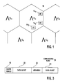
- FIG. 1 is an illustration of a wireless communication system 10.
- the communication system 10 has base stations 12 1 to 12 5 which communicate with user equipments (UEs) 14 1 to 14 3 .
- Each base station 12 1 has an associated operational area where it communicates with UEs 14 1 to 14 3 in its operational area.
- TDD/CDMA time division duplex using code division multiple access
- CDMA code division multiple access
- TDD/CDMA time division duplex using code division multiple access
- multiple communications are sent over the same frequency spectrum. These communications are typically differentiated by their chip code sequences.
- TDD/CDMA communication systems use repeating frames divided into time slots for communication. A communication sent in such a system will have one or multiple associated chip codes and time slots assigned to it based on the communication's bandwidth.
- a receiver in such a system must distinguish between the multiple communications.
- One approach to detecting such signals is single user detection.
- a receiver detects only the communication from a desired transmitter using a code associated with the desired transmitter, and treats signals of other transmitters as interference.
- joint detection In some situations, it is desirable to be able to detect multiple communications simultaneously in order to improve performance. Detecting multiple communications simultaneously is referred to as joint detection.
- Some joint detectors use Cholesky decomposition to perform a minimum mean square error (MMSE) detection and zero-forcing block equalizers (ZF-BLEs). These detectors have a high complexity requiring extensive receiver resources.
- MMSE minimum mean square error
- ZF-BLEs zero-forcing block equalizers
- a plurality of transmitted data signals are received at a receiver.
- the receiver measures a channel response associated with the transmitted data signals.
- a system response is determined.
- the system response is expanded to be piecewise orthogonal.
- the received data signals data is retrieved based on in part the expanded system response.
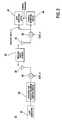
- Figure 2 illustrates a simplified transmitter 26 and receiver 28 using joint detection in a TDD/CDMA communication system.
- a transmitter 26 is in each UE 14 1 to 14 3 and multiple transmitting circuits 26 sending multiple communications are in each base station 12 1 to 12 5 .
- a base station 12 1 will typically require at least one transmitting circuit 26 for each actively communicating UE 14 1 to 14 3 .
- the joint detection receiver 28 may be at a base station 12 1 , UEs 14 1 to 14 3 or both.
- the joint detection receiver 28 receives communications from multiple transmitters 26 or transmitting circuits 26.
- Each transmitter 26 sends data over a wireless communication channel 30.
- a data generator 32 in the transmitter 26 generates data to be communicated over a reference channel to a receiver 28.
- Reference data is assigned to one or multiple codes and/or time slots based on the communications bandwidth requirements.
- a spreading and training sequence insertion device 34 spreads the reference channel data and makes the spread reference data time-multiplexed with a training sequence in the appropriate assigned time slots and codes. The resulting sequence is referred to as a communication burst.
- the communication burst is modulated by a modulator 36 to radio frequency.
- An antenna 38 radiates the RF signal through the wireless radio channel 30 to an antenna 40 of the receiver 28.
- the type of modulation used for the transmitted communication can be any of those known to those skilled in the art, such as direct phase shift keying (DPSK) or quadrature phase shift keying (QPSK).
- DPSK direct phase shift keying
- QPSK quadrature phase shift keying
- a typical communication burst 16 has a midamble 20, a guard period 18 and two data bursts 22, 24, as shown in Figure 3.
- the midamble 20 separates the two data bursts 22, 24 and the guard period 18 separates the communication bursts to allow for the difference in arrival times of bursts transmitted from different transmitters.
- the two data bursts 22, 24 contain the communication burst's data and are typically the same symbol length.
- the antenna 40 of the receiver 28 receives various radio frequency signals.
- the received signals are demodulated by a demodulator 42 to produce a baseband signal.
- the baseband signal is processed, such as by a channel estimation device 44 and a joint detection device 46, in the time slots and with the appropriate codes assigned to the communication bursts of the corresponding transmitters 26.
- the channel estimation device 44 uses the training sequence component in the baseband signal to provide channel information, such as channel impulse responses.
- the channel information is used by the joint detection device 46 to estimate the transmitted data of the received communication bursts as soft symbols.
- the joint detection device 46 uses the channel information provided by the channel estimation device 44 and the known spreading codes used by the transmitters 26 to estimate the data of the various received communication bursts. Although joint detection is described in conjunction with a TDD/CDMA communication system, the same approach is applicable to other communication systems, such as CDMA.
- FIG. 4 One approach to joint detection in a particular time slot in a TDD/CDMA communication system is illustrated in Figure 4.
- a number of communication bursts are superimposed on each other in the particular time slot, such as K communication bursts.
- the K bursts may be from K different transmitters. If certain transmitters are using multiple codes in the particular time slot, the K bursts may be from less than K transmitters.
- Each data burst 22, 24 of the communication burst 16 has a predefined number of transmitted symbols, such as N S .
- Each symbol is transmitted using a predetermined number of chips of the spreading code, which is the spreading factor (SF).
- SF spreading factor
- each base station 12 1 to 12 5 has an associated scrambling code mixed with its communicated data.
- the scrambling code distinguishes the base stations from one another.
- the scrambling code does not affect the spreading factor.
- the terms spreading code and factor are used hereafter, for systems using scrambling codes, the spreading code for the following is the combined scrambling and spreading codes.
- Each data burst 22, 24 has N S x SF chips.
- Equation 1 the known received combined chips, r , is a product of the system response, A, and the unknown transmitted symbols, d .
- the term, n represents the noise in the wireless radio channel.
- the number of data burst symbols to be recovered is Ns x K.
- the unknown data burst symbols are arranged into a column matrix, d .
- the d matrix has column blocks, d l to d Ns , of unknown data symbols.
- Each data symbol block, d i has the i th unknown transmitted data symbol in each of the K data bursts.
- each column block, d i has K unknown transmitted symbols stacked on top of each other.
- the blocks are also stacked in a column on top of each other, such that d 1 is on top of d 2 and so on.
- the joint detection device 46 receives a value for each chip as received.
- Each received chip is a composite of all K communication bursts.
- the composite chips are arranged into a column matrix, r .
- the matrix r has a value of each composite chip, totaling Ns * SF chips.
- A is the system response matrix.
- the system response matrix, A is formed by convolving the impulse responses with each communication burst chip code. The convolved result is rearranged to form the system response matrix, A (step 48).
- the joint detection device 46 receives the channel impulse response, h i , for each i th one of the K communication bursts from the channel estimation device 44. Each h i has a chip length of W.
- the joint detection device convolves the channel impulse responses with the known spreading codes of the K communication bursts to determine the symbol responses, s 1 to s K , of the K communication bursts.
- a common support sub-block, S, which is common to all of the symbol responses is of length K x (SF + W-1).
- the A matrix is arranged to have Ns blocks, B 1 to B NS .
- Each block has all of the symbol responses, s 1 , to s K , arranged to be multiplied with the corresponding unknown data block in the d matrix, d 1 to d Ns .
- d 1 is multiplied with B 1 .
- the symbol responses, s 1 to s K form a column in each block matrix, B i , with the rest of the block being padded with zeros.
- B 1 the symbol response row starts at the first row.
- the symbol response row is SF rows lower in the block and so on.
- each block has a width of K and a height of Ns x SF.
- Equation 2 illustrates an A block matrix showing the block partitions.
- the n matrix has a noise value corresponding to each received combined chip, totaling Ns x SF chips.
- the n matrix is implicit in the received combined chip matrix, r .
- Equation 1 can be rewritten as Equation 3.
- Equation 1 Using a noisy version of the r matrix, the value for each unknown symbol can be determined by solving the equation.
- a brute force approach to solving Equation 1 requires extensive processing.
- each block, B i is divided into Ns blocks having a width of K and a height of SF. These new blocks are referred to as A 1 to A L and 0.
- L is the length of the common support S, as divided by the height of the new blocks, A 1 to A L , per Equation 4.
- L ⁇ SF + W - 1 SF ⁇
- Blocks A 1 to A L are determined by the supports, s 1 to s K , and the common support, S.
- a 0 block is a block having all zeros.
- a repartitioned matrix for a system having a W of 57, SF of 16 and an L of 5 is shown in Equation 5.
- A A 1 0 0 0 0 0 0 0 ⁇ 0 0 0 A 2 A 1 0 0 0 0 ⁇ 0 0 0 A 3 A 2 A 1 0 0 0 0 ⁇ 0 0 0 0 A 4 A 3 A 2 A 1 0 0 0 ⁇ 0 0 0 0 A 5 A 4 A 3 A 2 A 1 0 0 ⁇ 0 0 0 0 0 0 A 5 A 4 A 3 A 2 A 1 0 ⁇ 0 0 0 0 0 0 0 A 5 A 4 A 3 A 2 A 1 ⁇ 0 0 0 0 0 0 0 0 A 5 A 4 A 3 A 2 A 1 ⁇ 0 0 0 0 0 0 0 0 0 A 5 A 4 A 3 A 2 A 1 ⁇ 0 0 0 0 0 0 0 0 0 A 5 A 4 A 3 A 2 ⁇ 0 0 0
- a piecewise orthogonalization approach is used. Any of the blocks B i for i being L or greater is non-orthogonal to any of the preceding L blocks and orthogonal to any blocks preceding by more than L. Each 0 in the repartitioned A matrix is an all zero block. As a result to use a piecewise orthogonalization, the A matrix is expanded (step 50).
- the A matrix is expanded by padding L-1 zero blocks to the right of each block of the A matrix and shifting each row in the A matrix by its row number less one.
- L-1 zero blocks
- A1 block in row 2 of Figure 2 four (L-1) zeros are inserted between A2 and A1 in row 2.
- block A1 (as well as A2) is shifted to the right by one column (row 2-1).
- Equation 5 after expansion would become Equation 6.
- a exp A 1 0 0 0 0 0 0 0 ⁇ 0 0 0 A 2 0 0 0 A 1 0 ⁇ 0 0 0 0 0 A 3 0 0 0 A 2 ⁇ 0 0 0 0 0 A 4 0 0 0 0 A 3 0 0 0 0 0 0 0 A 5 0 0 ⁇ A 4 0 0 0 0 0 0 0 0 0 0 0 0 0 ⁇ 0 A 5 0 ⁇ 0 0 0 0 0 0 0 0 0 0 0 0 0 0 0 0 0 0 0 0 0 0 0 0 0 0 0 0 0 0 0 0 0 0 0 0 0 0 0 0 0 0 0 0 0 0 0 0 0 0 0 0 0 0 0
- each block, d 1 to d Ns is expanded to a new block, d expl to d expNs .
- Each expanded block, d expl to d expNs is formed by repeating the original block L times. For example for d expl , a first block row would be created having L versions of d1 , stacked one below the other.
- Equation 1 can be rewritten as Equation 7.
- Equation 9 illustrates the QR decomposition of A exp .
- a exp Q exp ⁇ R exp Due to the orthogonal partitioning of A exp , the QR decomposition of A exp is less complex.
- the resulting Q exp and R exp matrices are periodic with an initial transient extending over L blocks. Accordingly, Q exp and R exp can be determined by calculating the initial transient and one period of the periodic portion. Furthermore, the periodic portion of the matrices is effectively determined by orthogonalizing A 1 to A L .
- One approach to QR decomposition is a Gramm-Schmidt orthogonalization.
- ⁇ Q i ⁇ are the orthonormal sets obtained by orthogonalizing ⁇ U j i ⁇ .
- U 1 2 needs to be orthogonalized with respect to only Q 2 of B exp1 formed previously.
- U 2 2 , U 3 2 and U 4 2 only need to be orthogonalized with respect to only Q 3 , Q 4 and Q 5 , respectively.
- U 5 2 needs to be ortogonalized to all previous Qs and its orthogonalized result is simply a shifted version of Q 5 obtained from orthogonalizing B exp1 .
- the orthogonalization of B exp5 is accomplished as follows. Its Q 5 is obtained by orthogonalizing As, and then zero padding. Its Q 4 is obtained by orthogonalizing the support of Q 5 and A 4 , [sup(Q 5 ) A 4 ], and then zero padding. Since sup(Q 5 ) is already an orthogonal set, only A 4 needs to be othogonalized with respect to sup(Q 5 ) and itself. Its Q 3 is obtained by orthogonalizing [sup(Q 5 ) sup(Q 4 ) A 3 ] and then zero padding.
- ⁇ A i ⁇ j is a block of size K ⁇ K representing the projections of each column of A i onto all the columns of Q j s .
- the first column of ⁇ A 4 ⁇ 5 represents the projections of the first column of A 4 on each of the K columns of Q 5 s .
- ⁇ A 4 ⁇ 4 represents the projections of the first column of A 4 on each of the K columns of Q 4 S .
- this block will be upper triangular, because the k th column of A 4 belongs to the space spanned by the orthonormal vectors of Q 5 S and the first k vectors of Q 4 S .
- the fifth block, U 5 s is formed by Q 5 S ⁇ ⁇ A 5 ⁇ ⁇ 5 .
- Equation 1.3 the coefficients in the expansion of subsequent B expi , i ⁇ 6 are simply periodic extensions of the above. Since the R exp entries are computed during the orthogonalization of A exp , no additional computations are needed to construct R exp . Disregarding the initial transient, the remainder of R exp is periodic, and two periods of it are shown in Equation 1.3.
- Tr 1 Tr 2 Tr 3 Tr 4 CF 5 0 0 0 0 ⁇ 0 Tr 1 Tr 2 CF 3 CF 4 CF 5 0 0 0 ⁇ 0 0 CF 1 CF 2 CF 3 CF 4 CF 5 0 0 0 ⁇ 0 0 0 CF 1 CF 2 CF 3 CF 4 CF 5 0 0 ⁇ 0 0 0 CF 1 CF 2 CF 3 CF 4 CF 5 0 0 ⁇ 0 0 0 CF 1 CF 2 CF 3 CF 4 CF 5 0 ⁇ ⁇ ⁇ ⁇ ⁇ ⁇ 0 ⁇ [ d 1 ⁇ d 2 ⁇ d 3 ⁇ ⁇ d N s ] r ⁇ ⁇ Tr 1 to Tr 4 are the transient terms and r ⁇ .
Landscapes
- Engineering & Computer Science (AREA)
- Physics & Mathematics (AREA)
- Mathematical Physics (AREA)
- General Physics & Mathematics (AREA)
- Pure & Applied Mathematics (AREA)
- Theoretical Computer Science (AREA)
- Mathematical Optimization (AREA)
- Signal Processing (AREA)
- Computational Mathematics (AREA)
- Computer Networks & Wireless Communication (AREA)
- Data Mining & Analysis (AREA)
- Mathematical Analysis (AREA)
- Software Systems (AREA)
- General Engineering & Computer Science (AREA)
- Databases & Information Systems (AREA)
- Algebra (AREA)
- Computing Systems (AREA)
- Mobile Radio Communication Systems (AREA)
Abstract
Description
- The invention generally relates to wireless communication systems. In particular, the invention relates to joint detection of multiple user signals in a wireless communication system.
- Figure 1 is an illustration of a
wireless communication system 10. Thecommunication system 10 has base stations 121 to 125 which communicate with user equipments (UEs) 141 to 143. Each base station 121 has an associated operational area where it communicates with UEs 141 to 143 in its operational area. - In some communication systems, such as code division multiple access (CDMA) and time division duplex using code division multiple access (TDD/CDMA), multiple communications are sent over the same frequency spectrum. These communications are typically differentiated by their chip code sequences. To more efficiently use the frequency spectrum, TDD/CDMA communication systems use repeating frames divided into time slots for communication. A communication sent in such a system will have one or multiple associated chip codes and time slots assigned to it based on the communication's bandwidth.
- Since multiple communications may be sent in the same frequency spectrum and at the same time, a receiver in such a system must distinguish between the multiple communications. One approach to detecting such signals is single user detection. In single user detection, a receiver detects only the communication from a desired transmitter using a code associated with the desired transmitter, and treats signals of other transmitters as interference.
- In some situations, it is desirable to be able to detect multiple communications simultaneously in order to improve performance. Detecting multiple communications simultaneously is referred to as joint detection. Some joint detectors use Cholesky decomposition to perform a minimum mean square error (MMSE) detection and zero-forcing block equalizers (ZF-BLEs). These detectors have a high complexity requiring extensive receiver resources.
- Accordingly, it is desirable to have alternate approaches to joint detection.
- A plurality of transmitted data signals are received at a receiver. The receiver measures a channel response associated with the transmitted data signals. A system response is determined. The system response is expanded to be piecewise orthogonal. The received data signals data is retrieved based on in part the expanded system response.
-
- Figure 1 is a wireless communication system.
- Figure 2 is a simplified transmitter and a receiver using joint detection.
- Figure 3 is an illustration of a communication burst.
- Figure 4 is an illustration of reduced computation joint detection.
- Figure 2 illustrates a
simplified transmitter 26 and receiver 28 using joint detection in a TDD/CDMA communication system. In a typical system, atransmitter 26 is in each UE 141 to 143 and multiple transmittingcircuits 26 sending multiple communications are in each base station 121 to 125. A base station 121 will typically require at least one transmittingcircuit 26 for each actively communicating UE 141 to 143. The joint detection receiver 28 may be at a base station 121, UEs 141 to 143 or both. The joint detection receiver 28 receives communications frommultiple transmitters 26 or transmittingcircuits 26. - Each
transmitter 26 sends data over awireless communication channel 30. Adata generator 32 in thetransmitter 26 generates data to be communicated over a reference channel to a receiver 28. Reference data is assigned to one or multiple codes and/or time slots based on the communications bandwidth requirements. A spreading and trainingsequence insertion device 34 spreads the reference channel data and makes the spread reference data time-multiplexed with a training sequence in the appropriate assigned time slots and codes. The resulting sequence is referred to as a communication burst. The communication burst is modulated by amodulator 36 to radio frequency. Anantenna 38 radiates the RF signal through thewireless radio channel 30 to anantenna 40 of the receiver 28. The type of modulation used for the transmitted communication can be any of those known to those skilled in the art, such as direct phase shift keying (DPSK) or quadrature phase shift keying (QPSK). - A
typical communication burst 16 has amidamble 20, aguard period 18 and twodata bursts midamble 20 separates the twodata bursts guard period 18 separates the communication bursts to allow for the difference in arrival times of bursts transmitted from different transmitters. The twodata bursts - The
antenna 40 of the receiver 28 receives various radio frequency signals. The received signals are demodulated by ademodulator 42 to produce a baseband signal. The baseband signal is processed, such as by achannel estimation device 44 and ajoint detection device 46, in the time slots and with the appropriate codes assigned to the communication bursts of thecorresponding transmitters 26. Thechannel estimation device 44 uses the training sequence component in the baseband signal to provide channel information, such as channel impulse responses. The channel information is used by thejoint detection device 46 to estimate the transmitted data of the received communication bursts as soft symbols. - The
joint detection device 46 uses the channel information provided by thechannel estimation device 44 and the known spreading codes used by thetransmitters 26 to estimate the data of the various received communication bursts. Although joint detection is described in conjunction with a TDD/CDMA communication system, the same approach is applicable to other communication systems, such as CDMA. - One approach to joint detection in a particular time slot in a TDD/CDMA communication system is illustrated in Figure 4. A number of communication bursts are superimposed on each other in the particular time slot, such as K communication bursts. The K bursts may be from K different transmitters. If certain transmitters are using multiple codes in the particular time slot, the K bursts may be from less than K transmitters.
- Each data burst 22, 24 of the
communication burst 16 has a predefined number of transmitted symbols, such as NS. Each symbol is transmitted using a predetermined number of chips of the spreading code, which is the spreading factor (SF). In a typical TDD communication system, each base station 121 to 125 has an associated scrambling code mixed with its communicated data. The scrambling code distinguishes the base stations from one another. Typically, the scrambling code does not affect the spreading factor. Although the terms spreading code and factor are used hereafter, for systems using scrambling codes, the spreading code for the following is the combined scrambling and spreading codes. Each data burst 22, 24 has NS x SF chips. - The
joint detection device 46 estimates the value that each data burst symbol was originally transmitted. Equation 1 is used to determine the unknown transmitted symbols.
- In Equation 1, the known received combined chips, r, is a product of the system response, A, and the unknown transmitted symbols, d. The term, n, represents the noise in the wireless radio channel.
- For K data bursts, the number of data burst symbols to be recovered is Ns x K. For analysis purposes, the unknown data burst symbols are arranged into a column matrix, d. The d matrix has column blocks, d l to d Ns, of unknown data symbols. Each data symbol block, d i, has the ith unknown transmitted data symbol in each of the K data bursts. As a result, each column block, d i, has K unknown transmitted symbols stacked on top of each other. The blocks are also stacked in a column on top of each other, such that d 1 is on top of d 2 and so on.
- The
joint detection device 46 receives a value for each chip as received. Each received chip is a composite of all K communication bursts. For analysis purposes, the composite chips are arranged into a column matrix, r. The matrix r has a value of each composite chip, totaling Ns * SF chips. - A is the system response matrix. The system response matrix, A, is formed by convolving the impulse responses with each communication burst chip code. The convolved result is rearranged to form the system response matrix, A (step 48).
- The
joint detection device 46 receives the channel impulse response, h i, for each ith one of the K communication bursts from thechannel estimation device 44. Each h i has a chip length of W. The joint detection device convolves the channel impulse responses with the known spreading codes of the K communication bursts to determine the symbol responses, s 1 to s K, of the K communication bursts. A common support sub-block, S, which is common to all of the symbol responses is of length K x (SF + W-1). - The A matrix is arranged to have Ns blocks, B1 to BNS. Each block has all of the symbol responses, s 1, to s K, arranged to be multiplied with the corresponding unknown data block in the d matrix, d 1 to d Ns. For example, d 1 is multiplied with B1. The symbol responses, s 1 to s K, form a column in each block matrix, Bi, with the rest of the block being padded with zeros. In the first block, B1, the symbol response row starts at the first row. In the second block, the symbol response row is SF rows lower in the block and so on. As a result, each block has a width of K and a height of Ns x SF. Equation 2 illustrates an A block matrix showing the block partitions.

- The n matrix has a noise value corresponding to each received combined chip, totaling Ns x SF chips. For analysis purposes, the n matrix is implicit in the received combined chip matrix, r.
- Using the block notation, Equation 1 can be rewritten as Equation 3.

- Using a noisy version of the r matrix, the value for each unknown symbol can be determined by solving the equation. However, a brute force approach to solving Equation 1 requires extensive processing.
- To reduce the processing, the system response matrix, A, is repartitioned. Each block, Bi, is divided into Ns blocks having a width of K and a height of SF. These new blocks are referred to as A1 to AL and 0. L is the length of the common support S, as divided by the height of the new blocks, A1 to AL, per
Equation 4.
- Blocks A1 to AL are determined by the supports, s 1 to s K, and the common support, S. A 0 block is a block having all zeros. A repartitioned matrix for a system having a W of 57, SF of 16 and an L of 5 is shown in
Equation 5.
- To reduce the complexity of the matrix, a piecewise orthogonalization approach is used. Any of the blocks Bi for i being L or greater is non-orthogonal to any of the preceding L blocks and orthogonal to any blocks preceding by more than L. Each 0 in the repartitioned A matrix is an all zero block. As a result to use a piecewise orthogonalization, the A matrix is expanded (step 50).
- The A matrix is expanded by padding L-1 zero blocks to the right of each block of the A matrix and shifting each row in the A matrix by its row number less one. To illustrate for the A1 block in row 2 of Figure 2, four (L-1) zeros are inserted between A2 and A1 in row 2. Additionally, block A1 (as well as A2) is shifted to the right by one column (row 2-1). As a result,
Equation 5 after expansion would become Equation 6.
- To accommodate the expanded A matrix, the d matrix must also be expanded, d exp. Each block, d 1 to d Ns, is expanded to a new block, d expl to d expNs. Each expanded block, d expl to d expNs, is formed by repeating the original block L times. For example for d expl, a first block row would be created having L versions of d1, stacked one below the other.
- As a result, Equation 1 can be rewritten as Equation 7.

- Equation 7 can be rewritten to partition each Bexpi orthogonally in L partitions, Uj (1), j = 1 to L, as in Equation 8.

- To reduce computational complexity, a QR decomposition of the Aexp matrix is performed (step 52). Equation 9 illustrates the QR decomposition of Aexp.

- To orthogonalize Aexp as in Equation 6, Bexp1 is othogonalized by independently orthogonalizing each of its orthogonal partitions,


- As the orthogonalizing continues, beyond the initial transient, there emerges a periodicity which can be summarized as follows. The result of orthogonalizing Bexpi, i ≥ 6 can be obtained simply by a periodic extension of the result of orthogonalizing Bexp5.
- The orthogonalization of Bexp5, is accomplished as follows. Its Q5 is obtained by orthogonalizing As, and then zero padding. Its Q4 is obtained by orthogonalizing the support of Q5 and A4, [sup(Q5) A4], and then zero padding. Since sup(Q5) is already an orthogonal set, only A4 needs to be othogonalized with respect to sup(Q5) and itself. Its Q3 is obtained by orthogonalizing [sup(Q5) sup(Q4) A3] and then zero padding. Its Q2 is obtained by orthogonalizing [sup(Q5) sup(Q4) sup(Q3) A2] and then zero padding. Its Q1 is obtained by orthogonalizing [sup(Q5) sup(Q4) sup(Q3) sup(Q2) A1] and then zero padding. Apart from the initial transient, the entire Aexp can be efficiently orthogonalized, by just orthogonalizing Ap per
Equation 10.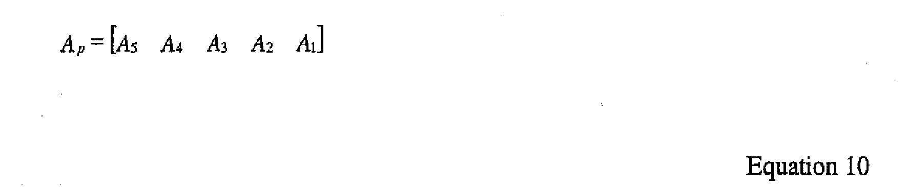
By effectively orthogonalizing the periodic portion of Aexp by using only Ap, computational efficiency is achieved. Using a more compact notation,

The periodic part of Qexp is per Equation 12.
- To constructing the upper triangular matrix Rexp,


triangular 

- The first block of Bexp5, viz.,


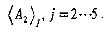


- Accordingly, the coefficients in the expansion of subsequent Bexpi, i ≥ 6 are simply periodic extensions of the above. Since the Rexp entries are computed during the orthogonalization of Aexp, no additional computations are needed to construct Rexp. Disregarding the initial transient, the remainder of Rexp is periodic, and two periods of it are shown in Equation 1.3.

The least squares approach to solving Qexp and Rexp is shown in Equation 14.
- By pre-multiplying both sides of Equation 14 by the transpose of Qexp ,


Equation 15 represents a triangular system whose solution also solves the LS problem of Equation 14. - Due to the expansion, the number of unknowns is increased by a factor of L. Since the unknowns are repeated by a factor of L, to reduce the complexity, the repeated unknowns can be collected to collapse the system. Rexp is collapsed using L coefficient blocks, CF1 to CFL, each having a width and a height of K. For a system having an L of 5, CF1 to CF5 can be determined as in
Equation 16.

Tr1 to Tr4 are the transient terms and r̂. By solving the upper triangle via back substitution, Equation 17 can be solved to determine d (step 56). As a result, the transmitted data symbols of the K data bursts is determined. - Using the piecewise orthogonalization and QR decomposition, the complexity of solving the least square problem when compared with a banded Cholesky decomposition is reduced by a factor of 6.5.
-
- 1. A method for use at a receiver of retrieving data from a plurality of data signals transmitted in a communication system, the method comprising:
- receiving the plurality of transmitted data signals at the receiver and measuring a channel response associated with the transmitted data signals;
- determining a system response based on in part the channel response;
- expanding the system response to be piecewise orthogonal; and
- retrieving data from the received data signals based on in part the expanded system response.
- 2. The method of item 1 wherein each of the transmitted data signals has an associated chip code and the system response is determined by convolving the associated chip codes with the channel response.
- 3. The method of item 1 wherein the system response is a system response matrix, further comprising dividing the system response matrix into blocks of columns prior to the expanding.
- 4. The method of item 3 wherein the expanding is by padding zeros in the column blocks to such that each block is orthogonal.
- 5. The method of item 3 wherein SF is a spreading factor associated with the data signals and W is a chip length associated with the channel response and the blocks contain L columns, where L is

- 6. The method of of item 1 further comprising QR decomposing the expanded system response.
- 7. The method of item wherein the QR decomposing is by Gramm-Schmitt orthogonalization.
- 8. The method of item 3 further comprising replacing elements of a column block with sub-blocks prior to the expanding.
- 9. The method of item 8 wherein in the sub-blocks have a same width as the column blocks and have a height associated with a length of a symbol response and a support of the symbol response.
- 10. The method of item 8 further comprising QR decomposing the system response matrix and orthogonalizing a periodic portion of a Q matrix is by orthogonalizing the sub-blocks.
- 11. The method of
item 10 further comprising orthogonalizing a periodic portion of an R matrix based on in part the orthogonalized sub-blocks associated with the Q matrix. - 12. The method of item 6 wherein the QR decomposing results in a Q matrix and an R matrix, each having an initial transient and a periodic portion.
- 13. The method of item 12 further comprising collapsing the R matrix by replacing elements in the R matrix with coefficient blocks.
- 14. The method of item 13 wherein the R matrix with coefficient blocks is a Cholesky-like factor.
- 15. A joint detection device for use in a receiver receiving a plurality of data signals, the joint detection device comprising:
- means for determining a system response based on in part a measured channel response;
- means for expanding the system response to be piecewise orthogonal; and
- means for retrieving data from the received data signals based on in part the expanded system response.
- 16. A receiver for receiving a plurality of transmitted data signals in a communication system, the receiver comprising:
- an antenna for receiving the transmitted data signals;
- a channel estimation device for determining a channel response for each received data signal; and
- a joint detection device having an input configured to receive the channel responses and the received data signals for determining a system response based on in part the channel signals, expanding the system response to be piecewise orthogonal, and retrieving data from the received data signals based on in part the expanded system response.
- 17. The receiver of
item 16 for use in a time division duplex using code division multiple access communication system. - 18. The receiver of item 17 wherein each of the transmitted data signals has an associate code and is transmitted in a shared frequency spectrum and the system response is determined by convolving the associated chip codes with the channel response.
- 19. The receiver of item 17 wherein the channel estimation device measures the channel response using a received training sequence associated with the data signals,
- 20. The receiver of
item 16 wherein the system response is a system response matrix, further comprising dividing the system response matrix into blocks of columns prior to the expanding. - 21. The receiver of
item 20 wherein the expanding is by padding zeros in the column blocks such that each column block is orthogonal. - 22. The receiver of
item 20 wherein SF is a spreading factor associated with the data signals and W is a chip length associated with the channel response and the blocks contain L columns, where L is
Claims (13)
- A user equipment for receiving a plurality of transmitted data signals in a communication system, the user equipment comprising:an antenna for receiving the transmitted data signals;a channel estimation device for determining a channel response for each received data signal;a joint detection device having an input connected with said channel estimation device to receive the channel responses and having an input connected with said antenna to receive received data signals; andsaid joint detection device configured to determine a system response based on in part the channel responses, configured to expand the system response to be piecewise orthogonal, and configured to retrieve data from the received data signals based on in part the expanded system response.
- The user equipment of claim 1 for use in a time division duplex using code division multiple access communication system wherein said joint detection device is connected to said antenna via a demodulator.
- The user equipment of claim 1 configured for use in a system where each of the transmitted data signals has an associate code and is transmitted in a shared frequency spectrum wherein said joint detection device is configured to determine the system response by convolving associated chip codes with the channel response.
- A user equipment for receiving a plurality of transmitted data signals in a communication system, the user equipment comprising:means for receiving the transmitted data signals;means for determining a channel response for each received data signal; andjoint detector means coupled with said receiving means and said determining means configured to determine a system response based on in part the channel responses, to expand the system response to be piecewise orthogonal, and to retrieve data from the received data signals based on in part the expanded system response.
- The user equipment of claim 4 for use in a time division duplex using code division multiple access communication system wherein said joint detector means is coupled with said receiving means via demodulator means.
- The user equipment of claim 4 configured for use in a system where each of the transmitted data signals has an associate code and is transmitted in a shared frequency spectrum wherein said joint detector means is configured to determine the system response by convolving associated chip codes with the channel response.
- A circuit for use in a receiver receiving a plurality of data signals, the circuit comprising:an input configured to receive the received data signals;means for determining a system response based on in part a measured channel response;means for expanding the system response to be piecewise orthogonal andmeans for retrieving data from the received data signals based on in part the expanded system response.
- A circuit for receiving a plurality of transmitted data signals, the circuit comprising:an antenna for receiving the transmitted data signals;a channel estimation device for determining a channel response for each received data signal; anda joint detection device having an input configured to receive the channel responses and the received data signals for determining a system response based on in part the channel signals, expanding the system response to be piecewise orthogonal, and retrieving data from the received data signals based on in part the expanded system response.
- The circuit of claim 8 for use in a time division duplex using code division multiple access communication system.
- The circuit of claim 9 wherein each of the transmitted data signals has an associate code and is transmitted in a shared frequency spectrum and the system response is determined by convolving the associated chip codes with the channel response.
- The circuit of claim 9 wherein the channel estimation device measures the channel response using a received training sequence associated with the data signals.
- The circuit of claim 8 wherein the system response is a system response matrix, further comprising dividing the system response matrix into blocks of columns prior to the expanding.
- The circuit of claim 12 wherein the expanding is by padding zeros in the column blocks such that each column block is orthogonal.
Applications Claiming Priority (3)
| Application Number | Priority Date | Filing Date | Title |
|---|---|---|---|
| US15380199P | 1999-09-14 | 1999-09-14 | |
| EP00963466A EP1212842B1 (en) | 1999-09-14 | 2000-09-14 | Reduced computation in joint detection |
| EP04009060A EP1453219B1 (en) | 1999-09-14 | 2000-09-14 | Reduced computation in joint detection |
Related Parent Applications (1)
| Application Number | Title | Priority Date | Filing Date |
|---|---|---|---|
| EP04009060A Division EP1453219B1 (en) | 1999-09-14 | 2000-09-14 | Reduced computation in joint detection |
Publications (1)
| Publication Number | Publication Date |
|---|---|
| EP1928103A1 true EP1928103A1 (en) | 2008-06-04 |
Family
ID=39333270
Family Applications (1)
| Application Number | Title | Priority Date | Filing Date |
|---|---|---|---|
| EP07150273A Withdrawn EP1928103A1 (en) | 1999-09-14 | 2000-09-14 | Reduced computation in joint detection |
Country Status (1)
| Country | Link |
|---|---|
| EP (1) | EP1928103A1 (en) |
-
2000
- 2000-09-14 EP EP07150273A patent/EP1928103A1/en not_active Withdrawn
Non-Patent Citations (1)
| Title |
|---|
| KARIMI H R ET AL: "A novel and efficient solution to block-based joint-detection using approximate Cholesky factorization", IEEE INTERNATIONAL SYMPOSIUM ON PERSONAL, INDOOR AND MOBILE RADIO COMMUNICATIONS,XX,XX, vol. 3, 1998, pages 1340 - 1345, XP002112134 * |
Similar Documents
| Publication | Publication Date | Title |
|---|---|---|
| US20080043875A1 (en) | Reduced computation in joint detection | |
| US7822103B2 (en) | Fast joint detection base station | |
| US7768986B2 (en) | Method and apparatus for receiving plurality of data signals | |
| US8218607B2 (en) | Data detection for codes with non-uniform spreading factors | |
| CN100403596C (en) | Efficient Multiple-Input Multiple-Output System for Multipath Fading Channels | |
| EP1212842B1 (en) | Reduced computation in joint detection | |
| US7027489B2 (en) | Iterative fast fourier transform error correction | |
| EP1453219B1 (en) | Reduced computation in joint detection | |
| HK1067999A (en) | Reduced computation in joint detection | |
| CA2483850A1 (en) | Reduced computation in joint detection | |
| EP1635525B1 (en) | Channel estimation for time division duplex communication systems |
Legal Events
| Date | Code | Title | Description |
|---|---|---|---|
| PUAI | Public reference made under article 153(3) epc to a published international application that has entered the european phase |
Free format text: ORIGINAL CODE: 0009012 |
|
| 17P | Request for examination filed |
Effective date: 20071220 |
|
| AC | Divisional application: reference to earlier application |
Ref document number: 1212842 Country of ref document: EP Kind code of ref document: P Ref document number: 1453219 Country of ref document: EP Kind code of ref document: P |
|
| AK | Designated contracting states |
Kind code of ref document: A1 Designated state(s): AT BE CH CY DE DK ES FI FR GB GR IE IT LI LU MC NL PT SE |
|
| AKX | Designation fees paid |
Designated state(s): AT BE CH CY DE DK ES FI FR GB GR IE IT LI LU MC NL PT SE |
|
| STAA | Information on the status of an ep patent application or granted ep patent |
Free format text: STATUS: THE APPLICATION IS DEEMED TO BE WITHDRAWN |
|
| 18D | Application deemed to be withdrawn |
Effective date: 20081205 |