EP1927788A1 - Transmission device having hydraulic motors and planetary gear - Google Patents
Transmission device having hydraulic motors and planetary gear Download PDFInfo
- Publication number
- EP1927788A1 EP1927788A1 EP06024950A EP06024950A EP1927788A1 EP 1927788 A1 EP1927788 A1 EP 1927788A1 EP 06024950 A EP06024950 A EP 06024950A EP 06024950 A EP06024950 A EP 06024950A EP 1927788 A1 EP1927788 A1 EP 1927788A1
- Authority
- EP
- European Patent Office
- Prior art keywords
- gear
- transmission device
- spur gear
- hydraulic motor
- coupled
- Prior art date
- Legal status (The legal status is an assumption and is not a legal conclusion. Google has not performed a legal analysis and makes no representation as to the accuracy of the status listed.)
- Ceased
Links
Images
Classifications
-
- F—MECHANICAL ENGINEERING; LIGHTING; HEATING; WEAPONS; BLASTING
- F16—ENGINEERING ELEMENTS AND UNITS; GENERAL MEASURES FOR PRODUCING AND MAINTAINING EFFECTIVE FUNCTIONING OF MACHINES OR INSTALLATIONS; THERMAL INSULATION IN GENERAL
- F16H—GEARING
- F16H47/00—Combinations of mechanical gearing with fluid clutches or fluid gearing
- F16H47/02—Combinations of mechanical gearing with fluid clutches or fluid gearing the fluid gearing being of the volumetric type
- F16H47/04—Combinations of mechanical gearing with fluid clutches or fluid gearing the fluid gearing being of the volumetric type the mechanical gearing being of the type with members having orbital motion
- F16H2047/045—Combinations of mechanical gearing with fluid clutches or fluid gearing the fluid gearing being of the volumetric type the mechanical gearing being of the type with members having orbital motion the fluid gearing comprising a plurality of pumps or motors
-
- F—MECHANICAL ENGINEERING; LIGHTING; HEATING; WEAPONS; BLASTING
- F16—ENGINEERING ELEMENTS AND UNITS; GENERAL MEASURES FOR PRODUCING AND MAINTAINING EFFECTIVE FUNCTIONING OF MACHINES OR INSTALLATIONS; THERMAL INSULATION IN GENERAL
- F16H—GEARING
- F16H3/00—Toothed gearings for conveying rotary motion with variable gear ratio or for reversing rotary motion
- F16H3/44—Toothed gearings for conveying rotary motion with variable gear ratio or for reversing rotary motion using gears having orbital motion
- F16H3/72—Toothed gearings for conveying rotary motion with variable gear ratio or for reversing rotary motion using gears having orbital motion with a secondary drive, e.g. regulating motor, in order to vary speed continuously
Definitions
- the invention relates to a transmission device for a vehicle, in particular a land vehicle, a self-propelled working machine or the like, with a planetary gear.
- transmission devices which comprise a plurality of input shafts and thereby be coupled to a plurality of hydraulic motors.
- a transmission device is for example already out of the DE 43 07 616 A1 can be seen, which comprises two drive shafts. Both drive shafts can each be coupled to a hydraulic motor and drive via two meshing spur gears to a central drive shaft. The drive shaft in turn drives, via two planetary gears operatively connected to one another, an output element which is designed as a Turas, a wheel or a winch. Targeted switching on and off of the individual hydraulic motors results in different speed ranges.
- a disadvantage of this known transmission device is to look at the fact that this is structurally relatively complicated and allows only a small spread of transmission.
- Object of the present invention is therefore to provide a transmission device of the type mentioned, which ensures a structurally simpler structure with increased transmission spread.
- the transmission device comprises a planetary gear, which at least one sun gear, which can be coupled via a first input shaft with a first hydraulic motor, a web, which with a Output shaft is coupled, at least one of the sun gear in operative connection planetary gear, which is coupled to the web and a standing with the at least one planet gear operatively connected ring gear, wherein additionally a first spur gear is provided, which is in operative connection with the ring gear and via a second input shaft can be coupled to a second hydraulic motor.
- the transmission device according to the invention therefore comprises - in contrast to the prior art - only a planetary gear and can be made simpler, more compact and space-saving.
- the transmission device according to the invention allows increased transmission spread, since not only the sun gear but also the ring gear can be driven.
- the transmission device allows switching operations without interruption of traction, which is for example when using vehicles in heavy terrain or high load of particular importance.
- a spur gear is provided, which is coupled to the ring gear and with the first spur gear in Active compound is. This allows while maintaining the space-saving construction a structurally advantageous possibility to adapt the desired transmission ratio of the second hydraulic motor to different requirement profiles or different vehicle types.
- the gear ratio between the spur gear and the first spur gear can be variably adjusted without the planetary gear of the transmission device would have to be changed in itself. Due to the high proportion of identical parts, therefore, further cost reductions can be achieved.
- a structurally advantageous and flexible embodiment of the transmission device to different vehicle types is further achieved in that the output shaft is assigned an output stage, via which a front axle and / or a rear axle of the vehicle is to be driven.
- an output stage via which a front axle and / or a rear axle of the vehicle is to be driven.
- first and the second input shaft are arranged axially parallel to each other and / or together on one of the output shaft opposite side of the transmission device. This allows the transmission device coupled with the hydraulic motors and integrated into the existing space.
- a braking device in particular a multi-disc brake, is provided, by means of which the ring gear is releasably fixed.
- This is a particularly material-friendly and easy to maintain means for fixing the ring gear or the second hydraulic motor coupled thereto, whereby different speed ranges or torque levels can be achieved.
- an additional drive stage is provided by the fact that the first input shaft, a second spur gear and the second input shaft, a third spur gear is associated with the second and the third spur gear are in operative connection with each other. That way, the first one and the second hydraulic motor are interconnected by means of the two spur gears and drive collectively on the sun gear.
- the first and / or the third spur gear are mounted on the second shaft. This allows the targeted decoupling of the first and / or third spur gear from the second drive shaft, so that any damage to the gear device is prevented when setting step-dependent different elements of the planetary gear.
- the second spur gear is disposed on the first input shaft in front of the sun gear and / or the third spur gear on the second input shaft in front of the first spur gear.
- the second and / or the third spur gear are arranged between the coupling regions of their respective input shafts with the hydraulic motors and the planetary gear.
- a first clutch device in particular a dog and / or multi-plate clutch, is provided by means of which the first and / or the third spur gear are decoupled from the second drive shaft is.
- the second drive shaft or the second hydraulic motor depending on the driving situation particularly easy in the drive train or be coupled out of this.
- a second clutch device in particular a claw and / or multi-plate clutch, is provided, by means of which the ring gear can be releasably fixed and / or coupled to the web.
- an additional driving step can be provided, on the other hand it is unnecessary Need to provide an additional braking device.
- the ring gear of the planetary gear can be fixed by means of the coupling device to an associated housing wall of the transmission device. It has also been found to be advantageous that the second clutch device comprises an idle position.
- a change between different speed levels or operating states of the transmission device can be carried out in a particularly simple and comfortable manner with the aid of an associated control device, by means of which the first hydraulic motor and / or the second hydraulic motor and / or the brake device and / or possibly the first clutch device and / or if necessary, the second coupling device is to be controlled.
- the said elements can be coordinated and centrally controlled to change the driving position, so that, for example, the transmission device can be designed as a power shift transmission without interruption of traction during the switching operations.
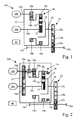
- Fig. 1 shows a schematic representation of a first embodiment of the transmission device 100 for a vehicle (not shown) with a drive stage.
- the transmission device 100 in this case comprises a planetary gear 10 with a sun gear 12, a web 14, which with a plurality of planetary gears 16 is coupled, and a ring gear 18a.
- the planetary gear 10 comprises in the present case, three planetary gears 16 (only one planetary gear shown), which are rotatably mounted on the web 14 and has the adjustable stand ratio i 0 .
- a different number of planetary gears 16 may be provided.
- the web 14 is coupled to an output shaft 20, which in turn via an output stage 22 with present three pairwise operatively connected gears 22a-c two cardan flanges 24a, b moves, via which a rear axle or front axle of the vehicle can be driven.
- an output stage 22 with present three pairwise operatively connected gears 22a-c two cardan flanges 24a, b moves, via which a rear axle or front axle of the vehicle can be driven.
- suitable choice of the teeth of the three gears 22a-c can be set particularly easy for the respective vehicle desired final ratio.
- alternative embodiments of the output stage 22 as well as the use of a different number of gears 22a-c are also conceivable.
- the sun gear 12 is coupled via a first input shaft 26a to a first hydraulic motor 28a and may be driven thereby.
- a spur gear 18b is connected, which has a reduced diameter relative to the ring gear 18a.
- the spur gear 18b is engaged with a first spur gear 30a, which is coupled via a second input shaft 26b to a second hydraulic motor 28b and can be driven thereby.
- mittexbart in the context of the invention, it is to be considered that the ring gear 18a is coupled to the spur gear 18b. It may be a one-piece or multi-part design.
- the transmission device 100 is presently arranged in a housing 32 which protects the mechanical elements contained from contamination or damage.
- a control device 40 is provided, which controls the hydraulic motors 28a, 28b in the present exemplary embodiment.
- the first hydraulic motor 28a drives the sun gear 12 of the planetary gear 10 with a torque T 1 whose ring gear 18a is held by the second hydraulic motor 28b via the first spur gear 30a coupled to the spur gear 18b.
- the torque T 2 of the second hydraulic motor 28b to the required Abstützmoment i 0 * T 1 of the ring gear 18 a aligned.
- the output of the planetary gear 10 via the output shaft 20 and the output stage 22 takes place on the web 14th
- the second hydraulic motor 28b is switched on.
- the ring gear 18a and the spur gear 18b rotate in the same direction as the sun gear 12 and continuously increase the final speed and thus the speed.
- the overall ratio is adjustable via the choice of the individual pairs of gears and the output stage 22 adjustable.
- Fig. 2 shows a schematic representation of a second embodiment of the transmission device 200 with two speed levels.
- the basic structure is already from the description Fig. 1 refer to.
- the present embodiment additionally comprises a braking device 34, by means of which the ring gear 18a is releasably fixed.
- the braking device 34 is designed, for example, as a multi-disc brake, but the person skilled in the art is also familiar with alternative embodiments.
- a second spur gear 30b is arranged between the first hydraulic motor 28a and the sun gear 12, which meshes with a third spur gear 30c arranged between the second hydraulic motor 28b and the first spur gear 30a.
- a first coupling device 36a is arranged, whose operation is explained in more detail below.
- the coupling device 36a may be formed, for example, as a claw or multi-plate clutch.
- the first and third spur gears 30a, c additionally include rolling bearings 38a, b on the second shaft.
- the transmission device 200 also comprises a control device 40, which controls the two hydraulic motors 28a, 28b as well as the switching operations between the speed stages.
- the clutch device 36a couples the second input shaft 26b to the third spur gear 30c.
- the ring gear 18a and the first spur gear 30a connected thereto via the spur gear 18b are fixed to the housing 32 by means of the brake device 34.
- the two hydraulic motors 28a, 28b jointly drive the sun gear 12 of the planetary gear 10 via the second and third spur gears 30b, c.
- the output takes place as before via the web 14 and the output shaft 20 to the output stage 22.
- the coupling device 36a couples the second input shaft 26b to the first spur gear 30a, so that the third spur gear 30c is in a freewheeling position via the bearing 38b.
- the brake device 34 is opened, thus releasing the ring gear 18a or the spur gear 18b.
- the function corresponds to that of Fig. 1 known embodiment. Again, the desired final translation can be adjusted as desired.
- the control device 40 switches the first clutch device 36a in idle position and brings the second hydraulic motor 28b to a standstill.
- the brake device 34 is opened and the ring gear 18a is held by the spur gear 18b and the first spur gear 30a by the support torque T 2 of the second hydraulic motor 28b.
- the drive takes place only by the first hydraulic motor 28a. The actuation of the individual switching elements does not have to be synchronized during upshifting, so that a simple switching position monitoring by the control device 40 is sufficient.
- the control device 40 For switching from the second to the first drive stage, the control device 40 first brings the second hydraulic motor 28b to a standstill and sets the ring gear 18a by means of the brake device 34. After the standstill of the ring gear 18a and the first spur gear 30a, the clutch device 36a is brought into an idling position. During this time, the drive takes place only via the first hydraulic motor 28a. The second hydraulic motor 28b is synchronized to the rotational speed of the third spur gear 30c and then via the coupling device 36a attached to this. The drive is thus carried out again with two hydraulic motors 28a, b on the sun gear 12 of the planetary gear 10. The change of speed steps takes place in each case without interruption of traction.
- the transmission range of the transmission device 100 according to the first exemplary embodiment can be further increased by the present transmission device 200.
- both high starting torques and high end speeds are possible.
- the second hydraulic motor 28b can then be switched on only when needed, for example, to allow an increase in the starting torque in the first driving step or an increase in the final speed in the second driving step.
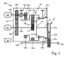
- Fig. 3 shows a schematic representation of a third embodiment of the transmission device 300 with three speed levels.
- the basic structure is already covered by the descriptions Fig. 1 respectively.
- Fig. 2 refer to.
- no braking device 34 is provided here.
- a second clutch device 36b takes over both clutch and brake tasks.
- separate coupling and braking devices can be provided.
- the first clutch device 36a couples the second input shaft 26b to the third spur gear 30c.
- the ring gear 18a of the planetary gear 10 and the first spur gear 30a operatively connected thereto via the spur gear 18b are fixed to the housing 32 by means of the second clutch device 30b.
- the two hydraulic motors 28a, 28b drive together the sun gear 12.
- the output takes place as before via the web 14 and the output shaft 20 to the output stage 22. This corresponds to the Fig. 2 known first gear.
- the first clutch device 36a couples the second input shaft 26b to the first spur gear 30a, whereby the third spur gear 30c is in an idle position via the bearing 38b.
- the second clutch device 36b is also connected in the neutral position and allows the rotation of the ring gear 18a and the spur gear 18b.
- the mode of operation thus corresponds to the first exemplary embodiment or the second drive stage of the second exemplary embodiment.
- the second clutch device 36b is coupled to the web 14.
- the planetary gear 10 is thus blocked and runs around as a block.
- the first clutch device 36a is in idle position and the second hydraulic motor 28b is shut down.
- the drive therefore takes place via the first hydraulic motor 28a directly to the output stage 22.
- the first clutch device 36a For switching from the first to the second drive stage, first the first clutch device 36a is switched to the neutral position and the second hydraulic motor 28b is brought to a standstill. Subsequently, the second clutch means 36b is switched to neutral position and thereby releases the ring gear 18a and the spur gear 18b. The required support torque T 2 is applied via the first spur gear 30a from the second hydraulic motor 28b. During the switching operation, the drive takes place via the first hydraulic motor 28a.
- the hydraulic motors 28a, 28b are controlled such that, in synchronous operation in the clutch device 36b, the ring gear 18a is coupled to the flywheel 14 of the planetary gear 10. Subsequently, the first coupling device 36a is brought into idle position and the second hydraulic motor 28b shut down.
- the second hydraulic motor 28b is controlled such that it is coupled to the first spur gear 30a during synchronous operation in the first clutch device 36a. Subsequently, the second clutch device 36 b is brought into idle position and allows the free superposition of the rotational speeds of the ring gear 18a and the spur gear 18b and the sun gear 12th
- the second hydraulic motor 28b is braked to a standstill and the ring gear 18a is fixed to the housing 32 with the second clutch device 36b. After the standstill of the ring gear 18a and the first spur gear 30a, the first clutch device 36a is brought into the neutral position. Meanwhile, the drive is only by the first hydraulic motor 28a.
- the second hydraulic motor 28b is synchronized to the rotational speed of the third spur gear 30c and then coupled via the first clutch device 36a to the rotating third spur gear 30c.
- the drive is now again with two hydraulic motors 28a, b on the sun gear 12 of the planetary gear 10th
- the transmission ranges of the previous transmission devices 100, 200 are further increased and allows in addition to high starting torque very high end speeds. Again, all switching operations without interruption of traction occur.
Abstract
Description
Die Erfindung betrifft eine Getriebevorrichtung für ein Fahrzeug, insbesondere ein Landfahrzeug, eine selbstfahrende Arbeitsmaschine oder dergleichen, mit einem Planetengetriebe.The invention relates to a transmission device for a vehicle, in particular a land vehicle, a self-propelled working machine or the like, with a planetary gear.
Bei verschiedenen Fahrzeugtypen, insbesondere bei im Baugewerbe oder in der Land- oder Forstwirtschaft verwendeten Zugmaschinen, Kombinationsfahrzeugen, selbstfahrenden Arbeitsmaschinen oder dergleichen, ist es erforderlich, eine möglichst breite Getriebespreizung zu gewährleisten, um den unterschiedlichen Betriebsanforderungen dieser Fahrzeuge Rechnung tragen zu können. Dazu zählt insbesondere das Erfordernis, die Fahrzeuge in mindestens zwei deutlich voneinander verschiedenen Geschwindigkeitsbereichen bewegen zu können. So müssen derartige Fahrzeuge einerseits mit möglichst hoher Zugkraft bei langsamer Fahrt, beispielsweise 2 km/h während des Bearbeitens eines Feldes oder bei Fahrten in schwerem Gelände, betrieben werden können. Andererseits müssen die Fahrzeuge beim Überstellen zum jeweiligen Einsatzort Geschwindigkeiten von 30 bis 40 km/h erreichen, um auch auf öffentlichen Straßen bewegt werden zu können.In various types of vehicles, especially in tractors used in construction or in agriculture or forestry, combination vehicles, self-propelled machines or the like, it is necessary to ensure the widest possible transmission spread in order to take into account the different operating requirements of these vehicles. This includes in particular the requirement to be able to move the vehicles in at least two distinctly different speed ranges. Thus, such vehicles must be able to operate on the one hand with the highest possible traction at slow speeds, for example, 2 km / h while working a field or when driving in difficult terrain. On the other hand, the vehicles must reach speeds of 30 to 40 km / h when transferring to the respective place of use in order to be able to be moved on public roads.
Zur Lösung dieser Problematik sind Getriebevorrichtungen bekannt, welche mehrere Eingangswellen umfassen und dadurch mit mehreren Hydromotoren koppelbar sind. Eine derartige Getriebevorrichtung ist beispielsweise bereits aus der
Als nachteilig an dieser bekannten Getriebevorrichtung ist dabei der Umstand anzusehen, dass diese konstruktiv vergleichsweise aufwendig ausgebildet ist und nur eine geringe Getriebespreizung zulässt.A disadvantage of this known transmission device is to look at the fact that this is structurally relatively complicated and allows only a small spread of transmission.
Aufgabe der vorliegenden Erfindung ist es daher, eine Getriebevorrichtung der eingangs genannten Art zu schaffen, welche einen konstruktiv einfacheren Aufbau mit einer erhöhten Getriebespreizung gewährleistet.Object of the present invention is therefore to provide a transmission device of the type mentioned, which ensures a structurally simpler structure with increased transmission spread.
Diese Aufgabe wird erfindungsgemäß durch eine Getriebevorrichtung mit den Merkmalen des Patentanspruchs 1 gelöst.This object is achieved by a transmission device with the features of claim 1.
Vorteilhafte Ausgestaltungen mit zweckmäßigen und nicht-trivialen Weiterbildungen der Erfindung sind in den Unteransprüchen angegeben.Advantageous embodiments with expedient and non-trivial developments of the invention are specified in the subclaims.
Um eine Getriebevorrichtung mit einem konstruktiv einfacheren Aufbau und einer erhöhten Getriebespreizung zu schaffen, ist es erfindungsgemäß vorgesehen, dass die Getriebevorrichtung ein Planetengetriebe umfasst, welches zumindest ein Sonnenrad, das über eine erste Eingangswelle mit einem ersten Hydromotor koppelbar ist, einen Steg, welcher mit einer Abtriebswelle gekoppelt ist, zumindest ein mit dem Sonnenrad in Wirkverbindung stehendes Planetenrad, welches mit dem Steg gekoppelt ist sowie ein mit dem zumindest einen Planetenrad in Wirkverbindung stehendes Hohlrad umfasst, wobei zusätzlich ein erstes Stirnrad vorgesehen ist, welches mit dem Hohlrad in Wirkverbindung steht und über eine zweite Eingangswelle mit einem zweiten Hydromotor koppelbar ist. Die erfindungsgemäße Getriebevorrichtung umfasst demnach - im Gegensatz zum Stand der Technik - lediglich ein Planetengetriebe und kann dadurch einfacher, kompakter und bauraumsparender ausgebildet werden. Darüber hinaus ermöglicht die erfindungsgemäße Getriebevorrichtung eine erhöhte Getriebespreizung, da nicht nur das Sonnenrad sondern auch das Hohlrad antreibbar sind. Zudem erlaubt die Getriebevorrichtung Schaltvorgänge ohne Zugkraftunterbrechung, was beispielsweise beim Einsatz von Fahrzeugen in schwerem Gelände oder mit hoher Beladung von besonderer Bedeutung ist.To provide a transmission device with a structurally simpler structure and increased transmission spread, it is provided according to the invention that the transmission device comprises a planetary gear, which at least one sun gear, which can be coupled via a first input shaft with a first hydraulic motor, a web, which with a Output shaft is coupled, at least one of the sun gear in operative connection planetary gear, which is coupled to the web and a standing with the at least one planet gear operatively connected ring gear, wherein additionally a first spur gear is provided, which is in operative connection with the ring gear and via a second input shaft can be coupled to a second hydraulic motor. The transmission device according to the invention therefore comprises - in contrast to the prior art - only a planetary gear and can be made simpler, more compact and space-saving. In addition, the transmission device according to the invention allows increased transmission spread, since not only the sun gear but also the ring gear can be driven. In addition, the transmission device allows switching operations without interruption of traction, which is for example when using vehicles in heavy terrain or high load of particular importance.
In einer vorteilhaften Ausgestaltung der Erfindung ist ein Stirnrad vorgesehen, welches mit dem Hohlrad gekoppelt ist und mit dem ersten Stirnrad in Wirkverbindung steht. Dies erlaubt unter Beibehaltung der bauraumsparenden Konstruktion eine konstruktiv vorteilhafte Möglichkeit, das gewünschte Übersetzungsverhältnis des zweiten Hydromotors an unterschiedliche Anforderungsprofile oder unterschiedliche Fahrzeugtypen anzupassen. Das Verzahnungsverhältnis zwischen Stirnrad und erstem Stirnrad kann variabel eingestellt werden, ohne dass das Planetengetriebe der Getriebevorrichtung an sich geändert werden müsste. Durch den hohen Anteil von Gleichteilen können daher weitere Kostensenkungen erzielt werden.In an advantageous embodiment of the invention, a spur gear is provided, which is coupled to the ring gear and with the first spur gear in Active compound is. This allows while maintaining the space-saving construction a structurally advantageous possibility to adapt the desired transmission ratio of the second hydraulic motor to different requirement profiles or different vehicle types. The gear ratio between the spur gear and the first spur gear can be variably adjusted without the planetary gear of the transmission device would have to be changed in itself. Due to the high proportion of identical parts, therefore, further cost reductions can be achieved.
Eine konstruktiv vorteilhafte und flexible Ausgestaltung der Getriebevorrichtung an unterschiedliche Fahrzeugtypen wird weiterhin dadurch erzielt, dass der Abtriebswelle eine Abtriebsstufe zugeordnet ist, über welche eine Vorderachse und/oder eine Hinterachse des Fahrzeugs anzutreiben ist. Durch eine derartige Abtriebsstufe kann sowohl die gewünschte Endübersetzung als auch die jeweilige Antriebsart den jeweiligen Erfordernissen und baulichen Gegebenheiten angepasst werden.A structurally advantageous and flexible embodiment of the transmission device to different vehicle types is further achieved in that the output shaft is assigned an output stage, via which a front axle and / or a rear axle of the vehicle is to be driven. By means of such an output stage, both the desired final ratio and the respective type of drive can be adapted to the respective requirements and structural conditions.
In einer weiteren vorteilhaften Ausgestaltung der Erfindung ist vorgesehen, dass die erste und die zweite Eingangswelle achsparallel zueinander und/oder gemeinsam auf einer der Abtriebswelle gegenüberliegenden Seite der Getriebevorrichtung angeordnet sind. Dadurch kann die Getriebevorrichtung mit den Hydromotoren gekoppelt und in den vorhandenen Bauraum integriert werden.In a further advantageous embodiment of the invention it is provided that the first and the second input shaft are arranged axially parallel to each other and / or together on one of the output shaft opposite side of the transmission device. This allows the transmission device coupled with the hydraulic motors and integrated into the existing space.
In einer weiteren vorteilhaften Ausgestaltung der Erfindung ist eine Bremsvorrichtung, insbesondere eine Lamellenbremse, vorgesehen, mittels welcher das Hohlrad lösbar festzulegen ist. Dies stellt ein besonders materialschonendes und wartungsfreundliches Mittel zum Festlegen des Hohlrads bzw. des damit koppelbaren zweiten Hydromotors dar, wodurch unterschiedliche Drehzahlbereiche bzw. Drehmomentstufen erreicht werden können.In a further advantageous embodiment of the invention, a braking device, in particular a multi-disc brake, is provided, by means of which the ring gear is releasably fixed. This is a particularly material-friendly and easy to maintain means for fixing the ring gear or the second hydraulic motor coupled thereto, whereby different speed ranges or torque levels can be achieved.
In weiterer vorteilhafter Ausgestaltung wird eine zusätzliche Fahrstufe dadurch bereitgestellt, dass der ersten Eingangswelle ein zweites Stirnrad und der zweiten Eingangswelle ein drittes Stirnrad zugeordnet ist, wobei das zweite und das dritte Stirnrad miteinander in Wirkverbindung stehen. Auf diese Weise können der erste und der zweite Hydromotor mittels der beiden Stirnräder zusammengeschaltet werden und gemeinsam auf das Sonnenrad eintreiben. Durch geeignete Wahl der jeweiligen Verzahnungen des zweiten und dritten Stirnrads kann zusätzlich eine besonders einfache Anpassung der Getriebevorrichtung an die Erfordernisse des jeweiligen Fahrzeugs vorgenommen werden. Dabei hat es sich weiterhin als vorteilhaft gezeigt, dass das erste und/oder das dritte Stirnrad auf der zweiten Welle gelagert sind. Dies ermöglicht das gezielte Entkoppeln des ersten und/oder dritten Stirnrads von der zweiten Antriebswelle, so dass eine etwaige Beschädigung der Getriebevorrichtung beim fahrstufenabhängigen Festlegen unterschiedlicher Elemente des Planetengetriebes verhindert wird.In a further advantageous embodiment, an additional drive stage is provided by the fact that the first input shaft, a second spur gear and the second input shaft, a third spur gear is associated with the second and the third spur gear are in operative connection with each other. That way, the first one and the second hydraulic motor are interconnected by means of the two spur gears and drive collectively on the sun gear. By a suitable choice of the respective toothings of the second and third spur gear, a particularly simple adaptation of the gear device to the requirements of the respective vehicle can additionally be carried out. It has further been found to be advantageous that the first and / or the third spur gear are mounted on the second shaft. This allows the targeted decoupling of the first and / or third spur gear from the second drive shaft, so that any damage to the gear device is prevented when setting step-dependent different elements of the planetary gear.
In einer weiteren vorteilhaften Ausgestaltung der Erfindung ist vorgesehen, dass das zweite Stirnrad auf der ersten Eingangswelle vor dem Sonnenrad und/oder das dritte Stirnrad auf der zweiten Eingangswelle vor dem ersten Stirnrad angeordnet ist. Mit anderen Worten sind das zweite und/oder das dritte Stirnrad zwischen den Kopplungsbereichen ihrer jeweiligen Eingangswellen mit den Hydromotoren und dem Planetengetriebe angeordnet. Dies ermöglicht einen kostensenkenden, modularen Aufbau der Getriebevorrichtung, bei dem lediglich die jeweils gewünschten Stirnräder auf den Eingangswellen des Planetengetriebes angeordnet werden müssen.In a further advantageous embodiment of the invention it is provided that the second spur gear is disposed on the first input shaft in front of the sun gear and / or the third spur gear on the second input shaft in front of the first spur gear. In other words, the second and / or the third spur gear are arranged between the coupling regions of their respective input shafts with the hydraulic motors and the planetary gear. This allows a cost-reducing, modular structure of the transmission device, in which only the respectively desired spur gears must be arranged on the input shafts of the planetary gear.
Um eine Getriebevorrichtung mit mehreren Fahrstufen bereitstellen zu können, hat es sich als vorteilhaft gezeigt, dass eine erste Kupplungseinrichtung, insbesondere eine Klauen- und/oder Lamellenkupplung, vorgesehen ist, mittels welcher das erste und/oder das dritte Stirnrad von der zweiten Antriebswelle zu entkoppeln ist. Dadurch kann die zweite Antriebswelle bzw. der zweite Hydromotor in Abhängigkeit der Fahrsituation besonders einfach in den Antriebsstrang ein- oder aus diesem ausgekoppelt werden.In order to be able to provide a transmission device with several drive stages, it has proven to be advantageous that a first clutch device, in particular a dog and / or multi-plate clutch, is provided by means of which the first and / or the third spur gear are decoupled from the second drive shaft is. As a result, the second drive shaft or the second hydraulic motor depending on the driving situation particularly easy in the drive train or be coupled out of this.
In einer weiteren vorteilhaften Ausgestaltung der Erfindung ist eine zweite Kupplungseinrichtung, insbesondere eine Klauen- und/oder Lamellenkupplung, vorgesehen, mittels welcher das Hohlrad lösbar festgelegt und/oder mit dem Steg gekoppelt werden kann. Durch eine derartige Kupplungseinrichtung kann zum einen eine zusätzliche Fahrstufe bereitgestellt werden, zum anderen entfällt die Notwendigkeit, eine zusätzliche Bremsvorrichtung vorsehen zu müssen. So kann in einfachster Ausgestaltung beispielsweise das Hohlrad des Planetengetriebes mittels der Kupplungseinrichtung an einer zugeordneten Gehäusewand der Getriebevorrichtung festgelegt werden. Dabei hat es sich ebenfalls als vorteilhaft gezeigt, dass die zweite Kupplungseinrichtung eine Leerlaufstellung umfasst.In a further advantageous embodiment of the invention, a second clutch device, in particular a claw and / or multi-plate clutch, is provided, by means of which the ring gear can be releasably fixed and / or coupled to the web. By means of such a coupling device, on the one hand, an additional driving step can be provided, on the other hand it is unnecessary Need to provide an additional braking device. Thus, in the simplest embodiment, for example, the ring gear of the planetary gear can be fixed by means of the coupling device to an associated housing wall of the transmission device. It has also been found to be advantageous that the second clutch device comprises an idle position.
Besonders einfach und komfortabel kann ein Wechsel zwischen verschiedenen Fahrstufen oder Betriebszuständen der Getriebevorrichtung mit Hilfe einer zugeordneten Steuereinrichtung erfolgen, mittels welcher der erste Hydromotor und/oder der zweite Hydromotor und/oder ggf. die Bremsvorrichtung und/oder ggf. die erste Kupplungseinrichtung und/oder ggf. die zweite Kupplungseinrichtung zu steuern ist. In Abhängigkeit der konkreten Ausgestaltung der Getriebevorrichtung können die besagten Elemente zum Wechseln der Fahrstufe koordiniert und zentral gesteuert werden, so dass beispielsweise die Getriebevorrichtung als Lastschaltgetriebe ohne Zugkraftunterbrechung während der Schaltvorgänge ausgebildet werden kann.A change between different speed levels or operating states of the transmission device can be carried out in a particularly simple and comfortable manner with the aid of an associated control device, by means of which the first hydraulic motor and / or the second hydraulic motor and / or the brake device and / or possibly the first clutch device and / or if necessary, the second coupling device is to be controlled. Depending on the specific configuration of the transmission device, the said elements can be coordinated and centrally controlled to change the driving position, so that, for example, the transmission device can be designed as a power shift transmission without interruption of traction during the switching operations.
Weitere Vorteile, Merkmale und Einzelheiten der Erfindung ergeben sich aus der nachfolgenden Beschreibung mehrerer Ausführungsbeispiele sowie anhand der Zeichnungen, in welchen gleiche oder funktionsgleiche Elemente mit gleichen Bezugszeichen versehen sind. Dabei zeigen:
- Fig. 1
- eine schematische Darstellung eines ersten Ausführungsbeispiels der Getriebevorrichtung mit einer Fahrstufe;
- Fig. 2
- eine schematische Darstellung eines zweiten Ausführungsbeispiels der Getriebevorrichtung mit zwei Fahrstufen; und
- Fig 3
- eine schematische Darstellung eines dritten Ausführungsbeispiels der Getriebevorrichtung mit drei Fahrstufen.
- Fig. 1
- a schematic representation of a first embodiment of the transmission device with a drive stage;
- Fig. 2
- a schematic representation of a second embodiment of the transmission device with two speed levels; and
- Fig. 3
- a schematic representation of a third embodiment of the transmission device with three speed levels.
Das Sonnenrad 12 ist über eine erste Eingangswelle 26a mit einem ersten Hydromotor 28a gekoppelt und kann durch diesen angetrieben werden. Mit dem Hohlrad 18a ist ein Stirnrad 18b verbunden, welches gegenüber dem Hohlrad 18a einen verringerten Durchmesser aufweist. Das Stirnrad 18b steht im Eingriff mit einem ersten Stirnrad 30a, welches über eine zweite Eingangswelle 26b mit einem zweiten Hydromotor 28b gekoppelt ist und von diesem angetrieben werden kann. Als im Rahmen der Erfindung mitoffenbart ist es dabei anzusehen, dass das Hohlrad 18a mit dem Stirnrad 18b gekoppelt ist. Es kann sich dabei um eine einteilige oder mehrteilige Ausgestaltung handeln. Die Getriebevorrichtung 100 ist vorliegend in einem Gehäuse 32 angeordnet, welches die enthaltenen mechanischen Elemente vor Verschmutzung oder Beschädigung schützt. Zusätzlich ist eine Steuereinrichtung 40 vorgesehen, die im vorliegenden Ausführungsbeispiel die Hydromotoren 28a,b steuert.The
Die Funktionsweise des vorliegenden Ausführungsbeispiels wird im Folgenden näher erläutert. Zum Anfahren des Fahrzeugs triebt der erste Hydromotor 28a mit einem Drehmoment T1 das Sonnenrad 12 des Planetengetriebes 10 an, dessen Hohlrad 18a über das mit dem Stirnrad 18b gekoppelte erste Stirnrad 30a vom zweiten Hydromotor 28b gehalten wird. Dazu wird über das erste Stirnrad 30a das Drehmoment T2 des zweiten Hydromotors 28b an das erforderliche Abstützmoment i0*T1 des Hohlrads 18a angeglichen. Der Abtrieb des Planetengetriebes 10 über die Abtriebswelle 20 bzw. die Abtriebsstufe 22 erfolgt am Steg 14.The operation of the present embodiment will be explained in more detail below. For starting the vehicle, the first
Nach dem Anfahren des Fahrzeugs wird der zweite Hydromotor 28b zugeschaltet. Dadurch drehen sich das Hohlrad 18a sowie das Stirnrad 18b im gleichen Drehsinn wie das Sonnenrad 12 und erhöhen stufenlos die Enddrehzahl und damit die Geschwindigkeit. Die Gesamtübersetzung ist variabel über die Wahl der einzelnen Verzahnungspaare und über die Abtriebsstufe 22 einstellbar. Durch den Verzicht auf Schaltelemente kann die vorliegende Ausführungsform einerseits besonders kostengünstig und kompakt ausgebildet werden, bietet andererseits aber trotzdem eine für die meisten Anwendungsbereiche ausreichende Getriebespreizung, wobei die stufenlose Erweiterung des Drehzahlbereichs darüber hinaus ohne Zugkraftunterbrechung erfolgt. Im Vergleich zu aus dem Stand der Technik bekannten Getriebevorrichtungen bzw. Fahrzeugen mit nur einem Hydromotor kann eine deutlich höhere Endgeschwindigkeit erzielt werden.After starting the vehicle, the second
In der ersten Fahrstufe koppelt die Kupplungseinrichtung 36a die zweite Eingangswelle 26b mit dem dritten Stirnrad 30c. Das Hohlrad 18a und das über das Stirnrad 18b mit diesen verbundene erste Stirnrad 30a werden mittels der Bremsvorrichtung 34 am Gehäuse 32 festgelegt. Die beiden Hydromotoren 28a,b treiben gemeinsam über das zweite und dritte Stirnrad 30b,c das Sonnenrad 12 des Planetengetriebes 10 an. Der Abtrieb erfolgt wie zuvor über den Steg 14 und die Abtriebswelle 20 auf die Abtriebsstufe 22. Die Gesamtübersetzung ergibt sich damit zu iges=(i0+1)*iA, wobei iA die Übersetzung des Abtriebs bezeichnet.In the first drive stage, the
In der zweiten Fahrstufe koppelt die Kupplungseinrichtung 36a die zweite Eingangswelle 26b mit dem ersten Stirnrad 30a, so dass sich das dritte Stirnrad 30c über das Lager 38b in einer Freilaufstellung befindet. Gleichzeitig ist die Bremsvorrichtung 34 geöffnet und gibt damit das Hohlrad 18a bzw. das Stirnrad 18b frei. Die Funktion entspricht damit der aus
Zum Schalten aus der ersten in die zweite Fahrstufe schaltet die Steuereinrichtung 40 die erste Kupplungseinrichtung 36a in Leerlaufstellung und bringt den zweiten Hydromotor 28b zum Stillstand. Im nächsten Schritt wird die Bremsvorrichtung 34 geöffnet und das Hohlrad 18a über das Stirnrad 18b und das erste Stirnrad 30a vom Abstützmoment T2 des zweiten Hydromotors 28b gehalten. Während des Schaltvorgangs erfolgt der Antrieb nur durch den ersten Hydromotor 28a. Die Betätigung der einzelnen Schaltelemente muss beim Hochschalten nicht synchronisiert werden, so dass eine einfache Schaltstellungsüberwachung durch die Steuereinrichtung 40 ausreichend ist.For switching from the first to the second gear stage, the
Zum Schalten aus der zweiten in die erste Fahrstufe bringt die Steuereinrichtung 40 zunächst den zweiten Hydromotor 28b zum Stillstand und legt das Hohlrad 18a mittels der Bremsvorrichtung 34 fest. Nach dem Stillstand des Hohlrads 18a und des ersten Stirnrads 30a wird die Kupplungseinrichtung 36a in eine Leerlaufstellung gebracht. In dieser Zeit erfolgt der Antrieb nur über den ersten Hydromotor 28a. Der zweite Hydromotor 28b wird auf die Drehzahl des dritten Stirnrads 30c synchronisiert und anschließend über die Kupplungseinrichtung 36a an dieses angekoppelt. Der Antrieb erfolgt damit wieder mit beiden Hydromotoren 28a,b auf das Sonnenrad 12 des Planetengetriebes 10. Der Wechsel der Fahrstufen erfolgt jeweils ohne Zugkraftunterbrechung.For switching from the second to the first drive stage, the
Durch die beiden Fahrstufen kann der Übersetzungsbereich der Getriebevorrichtung 100 gemäß dem ersten Ausführungsbeispiel durch die vorliegende Getriebevorrichtung 200 weiter erhöht werden. Gleichzeitig sind sowohl hohe Anfahrmomente als auch hohe Endgeschwindigkeiten möglich. Dabei kann weiterhin vorgesehen sein, dass bei Leerlaufstellung der Kupplungseinrichtung 36a und festgelegter Bremsvorrichtung 34 der Antrieb auch nur über den ersten Hydromotor 28a erfolgt. Der zweite Hydromotor 28b kann dann lediglich bei Bedarf zugeschaltet werden, um beispielsweise in der ersten Fahrstufe eine Erhöhung des Anfahrmoments oder in der zweiten Fahrstufe eine Erhöhung der Endgeschwindigkeit zu ermöglichen.As a result of the two drive stages, the transmission range of the
In der ersten Fahrstufe koppelt die erste Kupplungseinrichtung 36a die zweite Eingangswelle 26b mit dem dritten Stirnrad 30c. Das Hohlrad 18a des Planetengetriebes 10 und das mit diesem über das Stirnrad 18b in Wirkverbindung stehende erste Stirnrad 30a werden mittels der zweiten Kupplungseinrichtung 30b am Gehäuse 32 festgelegt. Die beiden Hydromotoren 28a,b treiben gemeinsam das Sonnenrad 12 an. Der Abtrieb erfolgt wie zuvor über den Steg 14 und die Abtriebswelle 20 auf die Abtriebsstufe 22. Dies entspricht der aus
In der zweiten Fahrstufe koppelt die erste Kupplungseinrichtung 36a die zweite Eingangswelle 26b mit dem ersten Stirnrad 30a, wodurch sich das dritte Stirnrad 30c über das Lager 38b in einer Leerlaufstellung befindet. Die zweite Kupplungseinrichtung 36b ist ebenfalls in Leerlaufstellung geschaltet und erlaubt die Drehung des Hohlrads 18a sowie des Stirnrads 18b. Die Funktionsweise entspricht damit dem ersten Ausführungsbeispiel bzw. der zweiten Fahrstufe des zweiten Ausführungsbeispiels.In the second drive stage, the first
In der dritten Fahrstufe ist die zweite Kupplungseinrichtung 36b mit dem Steg 14 gekoppelt. Das Planetengetriebe 10 ist damit blockiert und läuft als Block um. Die erste Kupplungseinrichtung 36a befindet sich dabei in Leerlaufstellung und der zweite Hydromotor 28b ist stillgelegt. Der Antrieb erfolgt daher über den ersten Hydromotor 28a direkt auf die Abtriebsstufe 22. Die Gesamtübersetzung ist nur von der Abtriebsstufe 22 abhängig und ergibt sich zu iges=iA.In the third drive stage, the second
Zum Schalten aus der ersten in die zweite Fahrstufe wird zunächst die erste Kupplungseinrichtung 36a in Leerlaufstellung geschaltet und der zweite Hydromotor 28b zum Stillstand gebracht. Anschließend wird die zweite Kupplungseinrichtung 36b in Leerlaufstellung geschaltet und gibt dadurch das Hohlrad 18a sowie das Stirnrad 18b frei. Das erforderliche Abstützmoment T2 wird dabei über das erste Stirnrad 30a vom zweiten Hydromotor 28b aufgebracht. Während des Schaltvorgangs erfolgt der Antrieb über den ersten Hydromotor 28a.For switching from the first to the second drive stage, first the first
Zum Schalten aus der zweiten in die dritte Fahrstufe werden die Hydromotoren 28a,b so gesteuert, dass bei Synchronlauf in der Kupplungseinrichtung 36b das Hohlrad 18a mit dem gleichschnell drehenden Steg 14 des Planetengetriebes 10 gekoppelt wird. Anschließend wird die erste Kupplungseinrichtung 36a in Leerlaufstellung gebracht und der zweite Hydromotor 28b stillgelegt.For switching from the second to the third drive stage, the
Zum Zurückschalten aus der dritten in die zweite Fahrstufe wir der zweite Hydromotor 28b so gesteuert, dass er bei Synchronlauf in der ersten Kupplungseinrichtung 36a an das erste Stirnrad 30a gekoppelt wird. Anschließend wird die zweite Kupplungseinrichtung 36b in Leerlaufstellung gebracht und ermöglicht die freie Überlagerung der Drehzahlen des Hohlrads 18a bzw. des Stirnrads 18b und des Sonnenrads 12.For switching back from the third to the second gear stage, the second
Zum Zurückschalten aus der zweiten in die erste Fahrstufe wird der zweite Hydromotor 28b zum Stillstand gebremst und das Hohlrad 18a mit der zweiten Kupplungseinrichtung 36b am Gehäuse 32 festgelegt. Nach dem Stillstand des Hohlrads 18a und des ersten Stirnrads 30a wir die erste Kupplungseinrichtung 36a in Leerlaufstellung gebracht. Währenddessen erfolgt der Antrieb nur durch den ersten Hydromotor 28a. Der zweite Hydromotor 28b wird auf die Drehzahl des dritten Stirnrads 30c synchronisiert und anschließend über die erste Kupplungseinrichtung 36a an das rotierende dritte Stirnrad 30c gekoppelt. Der Antrieb erfolgt jetzt wieder mit beiden Hydromotoren 28a,b auf das Sonnenrad 12 des Planetengetriebes 10.For switching back from the second to the first drive stage, the second
Durch die dritte Fahrstufe werden die Übersetzungsbereiche der vorherigen Getriebevorrichtungen 100, 200 weiter erhöht und ermöglicht neben hohen Anfahrmomenten sehr hohe Endgeschwindigkeiten. Auch hier erfolgen alle Schaltvorgänge ohne Zugkraftunterbrechung.By the third gear, the transmission ranges of the
Claims (12)
dadurch gekennzeichnet,
dass ein Stirnrad (18b) vorgesehen ist, welches mit dem Hohlrad (18a) gekoppelt ist und mit dem ersten Stirnrad (30a) in Wirkverbindung steht.Transmission device according to claim 1,
characterized,
in that a spur gear (18b) is provided which is coupled to the ring gear (18a) and is in operative connection with the first spur gear (30a).
dadurch gekennzeichnet,
dass der Abtriebswelle (20) eine Abtriebsstufe (22) zugeordnet ist, über weiche eine Vorderachse und/oder eine Hinterachse des Fahrzeugs anzutreiben ist.Transmission device according to claim 1 or 2,
characterized,
that the output shaft (20) an output stage (22) is associated to drive over soft a front axle and / or a rear axle of the vehicle.
dadurch gekennzeichnet,
dass die erste und die zweite Eingangswelle (26a,b) achsparallel zueinander und/oder gemeinsam auf einer der Abtriebswelle (20) gegenüberliegenden Seite der Getriebevorrichtung (100, 200, 300) angeordnet sind.Transmission device according to one of claims 1 to 3,
characterized,
in that the first and second input shafts (26a, b) are arranged axially parallel to one another and / or together on an opposite side of the transmission device (100, 200, 300) from the output shaft (20).
dadurch gekennzeichnet,
dass eine Bremsvorrichtung (34), insbesondere eine Lamellenbremse, vorgesehen ist, mittels welcher das Hohlrad (18a) lösbar festzulegen ist.Transmission device according to one of claims 1 to 4,
characterized,
in that a brake device (34), in particular a multi-disc brake, is provided, by means of which the ring gear (18a) is releasably fixed.
dadurch gekennzeichnet,
dass der ersten Eingangswelle (26a) ein zweites Stirnrad (30b) und der zweiten Eingangswelle (26b) ein drittes Stirnrad (30c) zugeordnet ist, wobei das zweite und das dritte Stirnrad (30b,c) miteinander in Wirkverbindung stehen.Transmission device according to one of claims 1 to 5,
characterized,
that the first input shaft (26a) a second spur gear (30b) and the second input shaft (26b) is associated with a third spur gear (30c), wherein the second stand and the third spur gear (30b, c) operatively connected together.
dadurch gekennzeichnet,
dass das erste und/oder das dritte Stirnrad (30a,c) ein Lager (38a,b) umfassen.Transmission device according to claim 6,
characterized,
in that the first and / or the third spur gear (30a, c) comprise a bearing (38a, b).
dadurch gekennzeichnet,
dass das zweite Stirnrad (30b) auf der ersten Eingangswelle (26a) vor dem Sonnenrad (12) und/oder das dritte Stirnrad (30c) auf der zweiten Eingangswelle (26b) vor dem ersten Stirnrad (30a) angeordnet ist.Transmission device according to claim 6 or 7,
characterized,
in that the second spur gear (30b) is arranged on the first input shaft (26a) in front of the sun gear (12) and / or the third spur gear (30c) on the second input shaft (26b) in front of the first spur gear (30a).
dadurch gekennzeichnet,
dass eine erste Kupplungseinrichtung (36a), insbesondere eine Klauen- und/oder Lamellenkupplung, vorgesehen ist, mittels welcher das erste und/oder das dritte Stirnrad (30a,c) von der zweiten Antriebswelle (26b) zu entkoppeln ist.Transmission device according to one of claims 6 to 8,
characterized,
in that a first coupling device (36a), in particular a claw and / or multi-plate clutch, is provided, by means of which the first and / or the third spur gear (30a, c) is to be decoupled from the second drive shaft (26b).
dadurch gekennzeichnet,
dass eine zweite Kupplungseinrichtung (36b), insbesondere eine Klauen- und/oder Lamellenkupplung, vorgesehen ist, mittels welcher das Hohlrad (18a) lösbar festzulegen und/oder mit dem Steg (14) zu koppeln ist.Transmission device according to one of claims 1 to 9,
characterized,
in that a second coupling device (36b), in particular a claw and / or multi-plate clutch, is provided, by means of which the ring gear (18a) is detachably fixed and / or to be coupled to the web (14).
dadurch gekennzeichnet,
dass die zweite Kupplungseinrichtung (36b) eine Leerlaufstellung umfasst.Transmission device according to claim 10,
characterized,
in that the second clutch device (36b) comprises an idling position.
dadurch gekennzeichnet,
dass eine Steuereinrichtung (40) vorgesehen ist, mittels welcher der erste Hydromotor (28a) und/oder der zweite Hydromotor (28b) und/oder ggf. die Bremsvorrichtung (34) und/oder ggf. die erste Kupplungseinrichtung (36a) und/oder ggf. die zweite Kupplungseinrichtung (36b) zu steuern ist.Transmission device according to one of claims 1 to 11,
characterized,
that a control device (40) is provided, by means of which the first hydraulic motor (28a) and / or the second hydraulic motor (28b) and / or if necessary, the braking device (34) and / or, if the first clutch device (36a) and / or if necessary, the second coupling device (36b) is to be controlled.
Priority Applications (1)
| Application Number | Priority Date | Filing Date | Title |
|---|---|---|---|
| EP06024950A EP1927788A1 (en) | 2006-12-01 | 2006-12-01 | Transmission device having hydraulic motors and planetary gear |
Applications Claiming Priority (1)
| Application Number | Priority Date | Filing Date | Title |
|---|---|---|---|
| EP06024950A EP1927788A1 (en) | 2006-12-01 | 2006-12-01 | Transmission device having hydraulic motors and planetary gear |
Publications (1)
| Publication Number | Publication Date |
|---|---|
| EP1927788A1 true EP1927788A1 (en) | 2008-06-04 |
Family
ID=37995282
Family Applications (1)
| Application Number | Title | Priority Date | Filing Date |
|---|---|---|---|
| EP06024950A Ceased EP1927788A1 (en) | 2006-12-01 | 2006-12-01 | Transmission device having hydraulic motors and planetary gear |
Country Status (1)
| Country | Link |
|---|---|
| EP (1) | EP1927788A1 (en) |
Cited By (2)
| Publication number | Priority date | Publication date | Assignee | Title |
|---|---|---|---|---|
| EP2249063A1 (en) * | 2009-05-06 | 2010-11-10 | Deere & Company | Transmission for a vehicle |
| RU181158U1 (en) * | 2016-12-07 | 2018-07-05 | Геннадий Антонович Телекало | TRANSMISSION-FREE TRANSMISSION |
Citations (4)
| Publication number | Priority date | Publication date | Assignee | Title |
|---|---|---|---|---|
| DE1918954A1 (en) * | 1969-04-15 | 1970-10-22 | Zahnradfabrik Friedrichshafen | Adjustable planetary gear |
| FR2210254A5 (en) * | 1972-12-08 | 1974-07-05 | Leboime Pierre | |
| EP0465752A1 (en) * | 1990-06-20 | 1992-01-15 | Aragonesa De Equipamientos Para Automoviles, S.A. | Continuous gear change mechanism |
| US5709628A (en) * | 1994-02-16 | 1998-01-20 | Pidde; Gerd | Hydrostatic transmission for construction machine |
-
2006
- 2006-12-01 EP EP06024950A patent/EP1927788A1/en not_active Ceased
Patent Citations (4)
| Publication number | Priority date | Publication date | Assignee | Title |
|---|---|---|---|---|
| DE1918954A1 (en) * | 1969-04-15 | 1970-10-22 | Zahnradfabrik Friedrichshafen | Adjustable planetary gear |
| FR2210254A5 (en) * | 1972-12-08 | 1974-07-05 | Leboime Pierre | |
| EP0465752A1 (en) * | 1990-06-20 | 1992-01-15 | Aragonesa De Equipamientos Para Automoviles, S.A. | Continuous gear change mechanism |
| US5709628A (en) * | 1994-02-16 | 1998-01-20 | Pidde; Gerd | Hydrostatic transmission for construction machine |
Cited By (3)
| Publication number | Priority date | Publication date | Assignee | Title |
|---|---|---|---|---|
| EP2249063A1 (en) * | 2009-05-06 | 2010-11-10 | Deere & Company | Transmission for a vehicle |
| CN101881326A (en) * | 2009-05-06 | 2010-11-10 | 迪尔公司 | Transmission device with dual stepless speed variator and planetary gear set |
| RU181158U1 (en) * | 2016-12-07 | 2018-07-05 | Геннадий Антонович Телекало | TRANSMISSION-FREE TRANSMISSION |
Similar Documents
| Publication | Publication Date | Title |
|---|---|---|
| EP1926620B1 (en) | Drive system for a vehicle, and agricultural vehicle | |
| DE60318490T2 (en) | CONTINUOUS GEARBOX WITH POWER BRANCH AND ELECTRICAL VARIATOR | |
| EP2018492B1 (en) | Transmission device for distributing a drive torque to at least two output shafts | |
| DE102019204909B4 (en) | Transmission, transmission assembly and drive train | |
| WO2014154416A1 (en) | Transmission for a motor vehicle | |
| DE3726080A1 (en) | HYDROMECHANICAL POWER BRANCHING GEARBOX FOR A VEHICLE | |
| WO2016096312A1 (en) | Gearing for a motor vehicle, a drive train, and a method for operating same | |
| DE102019119954B4 (en) | Drive device for a motor vehicle with a common rigid ring gear and a common rigid planet carrier | |
| DE102017222705A1 (en) | Transmission for a motor vehicle | |
| DE102019200966B4 (en) | Power-split motor vehicle transmission | |
| WO2020078627A1 (en) | Transmission for a motor vehicle | |
| EP1927788A1 (en) | Transmission device having hydraulic motors and planetary gear | |
| WO2021062458A1 (en) | Transmission arrangement | |
| DE2828204A1 (en) | TRANSMISSION MECHANISM FOR MOTOR VEHICLES | |
| DE102017216296B4 (en) | Hybrid unit for a motor vehicle | |
| DE102017216295B4 (en) | Hybrid unit for a motor vehicle | |
| EP3034348A1 (en) | Distributor gear for dividing a torque to at least a first and a second axle shaft of a motor vehicle | |
| WO2015043694A1 (en) | Torque transmission device for a motor vehicle | |
| DE102020201775B3 (en) | Power-split continuously variable transmission | |
| DE102017222724A1 (en) | Transmission for a motor vehicle | |
| WO2018197126A1 (en) | Transmission for a motor vehicle | |
| DE102022204751B4 (en) | Axle system, drive system and vehicle | |
| DE102017222710A1 (en) | Transmission for a motor vehicle | |
| DE102017216301A1 (en) | Transmission for a motor vehicle | |
| DE102020202419B3 (en) | Power-split continuously variable transmission |
Legal Events
| Date | Code | Title | Description |
|---|---|---|---|
| PUAI | Public reference made under article 153(3) epc to a published international application that has entered the european phase |
Free format text: ORIGINAL CODE: 0009012 |
|
| AK | Designated contracting states |
Kind code of ref document: A1 Designated state(s): AT BE BG CH CY CZ DE DK EE ES FI FR GB GR HU IE IS IT LI LT LU LV MC NL PL PT RO SE SI SK TR |
|
| AX | Request for extension of the european patent |
Extension state: AL BA HR MK RS |
|
| STAA | Information on the status of an ep patent application or granted ep patent |
Free format text: STATUS: THE APPLICATION HAS BEEN REFUSED |
|
| 18R | Application refused |
Effective date: 20080629 |