EP1927762A1 - Working fluid cooling control system of construction machine - Google Patents
Working fluid cooling control system of construction machine Download PDFInfo
- Publication number
- EP1927762A1 EP1927762A1 EP06797983A EP06797983A EP1927762A1 EP 1927762 A1 EP1927762 A1 EP 1927762A1 EP 06797983 A EP06797983 A EP 06797983A EP 06797983 A EP06797983 A EP 06797983A EP 1927762 A1 EP1927762 A1 EP 1927762A1
- Authority
- EP
- European Patent Office
- Prior art keywords
- working fluid
- hydraulic
- temperature
- control
- minimum
- Prior art date
- Legal status (The legal status is an assumption and is not a legal conclusion. Google has not performed a legal analysis and makes no representation as to the accuracy of the status listed.)
- Granted
Links
Images



Classifications
-
- E—FIXED CONSTRUCTIONS
- E02—HYDRAULIC ENGINEERING; FOUNDATIONS; SOIL SHIFTING
- E02F—DREDGING; SOIL-SHIFTING
- E02F9/00—Component parts of dredgers or soil-shifting machines, not restricted to one of the kinds covered by groups E02F3/00 - E02F7/00
- E02F9/20—Drives; Control devices
- E02F9/22—Hydraulic or pneumatic drives
- E02F9/226—Safety arrangements, e.g. hydraulic driven fans, preventing cavitation, leakage, overheating
-
- F—MECHANICAL ENGINEERING; LIGHTING; HEATING; WEAPONS; BLASTING
- F15—FLUID-PRESSURE ACTUATORS; HYDRAULICS OR PNEUMATICS IN GENERAL
- F15B—SYSTEMS ACTING BY MEANS OF FLUIDS IN GENERAL; FLUID-PRESSURE ACTUATORS, e.g. SERVOMOTORS; DETAILS OF FLUID-PRESSURE SYSTEMS, NOT OTHERWISE PROVIDED FOR
- F15B21/00—Common features of fluid actuator systems; Fluid-pressure actuator systems or details thereof, not covered by any other group of this subclass
- F15B21/04—Special measures taken in connection with the properties of the fluid
-
- E—FIXED CONSTRUCTIONS
- E02—HYDRAULIC ENGINEERING; FOUNDATIONS; SOIL SHIFTING
- E02F—DREDGING; SOIL-SHIFTING
- E02F9/00—Component parts of dredgers or soil-shifting machines, not restricted to one of the kinds covered by groups E02F3/00 - E02F7/00
- E02F9/20—Drives; Control devices
- E02F9/22—Hydraulic or pneumatic drives
-
- E—FIXED CONSTRUCTIONS
- E02—HYDRAULIC ENGINEERING; FOUNDATIONS; SOIL SHIFTING
- E02F—DREDGING; SOIL-SHIFTING
- E02F9/00—Component parts of dredgers or soil-shifting machines, not restricted to one of the kinds covered by groups E02F3/00 - E02F7/00
- E02F9/20—Drives; Control devices
- E02F9/22—Hydraulic or pneumatic drives
- E02F9/2278—Hydraulic circuits
- E02F9/2292—Systems with two or more pumps
-
- E—FIXED CONSTRUCTIONS
- E02—HYDRAULIC ENGINEERING; FOUNDATIONS; SOIL SHIFTING
- E02F—DREDGING; SOIL-SHIFTING
- E02F9/00—Component parts of dredgers or soil-shifting machines, not restricted to one of the kinds covered by groups E02F3/00 - E02F7/00
- E02F9/20—Drives; Control devices
- E02F9/22—Hydraulic or pneumatic drives
- E02F9/2278—Hydraulic circuits
- E02F9/2296—Systems with a variable displacement pump
-
- F—MECHANICAL ENGINEERING; LIGHTING; HEATING; WEAPONS; BLASTING
- F15—FLUID-PRESSURE ACTUATORS; HYDRAULICS OR PNEUMATICS IN GENERAL
- F15B—SYSTEMS ACTING BY MEANS OF FLUIDS IN GENERAL; FLUID-PRESSURE ACTUATORS, e.g. SERVOMOTORS; DETAILS OF FLUID-PRESSURE SYSTEMS, NOT OTHERWISE PROVIDED FOR
- F15B11/00—Servomotor systems without provision for follow-up action ; Circuits therefor
-
- F—MECHANICAL ENGINEERING; LIGHTING; HEATING; WEAPONS; BLASTING
- F15—FLUID-PRESSURE ACTUATORS; HYDRAULICS OR PNEUMATICS IN GENERAL
- F15B—SYSTEMS ACTING BY MEANS OF FLUIDS IN GENERAL; FLUID-PRESSURE ACTUATORS, e.g. SERVOMOTORS; DETAILS OF FLUID-PRESSURE SYSTEMS, NOT OTHERWISE PROVIDED FOR
- F15B21/00—Common features of fluid actuator systems; Fluid-pressure actuator systems or details thereof, not covered by any other group of this subclass
- F15B21/04—Special measures taken in connection with the properties of the fluid
- F15B21/042—Controlling the temperature of the fluid
- F15B21/0423—Cooling
-
- F—MECHANICAL ENGINEERING; LIGHTING; HEATING; WEAPONS; BLASTING
- F15—FLUID-PRESSURE ACTUATORS; HYDRAULICS OR PNEUMATICS IN GENERAL
- F15B—SYSTEMS ACTING BY MEANS OF FLUIDS IN GENERAL; FLUID-PRESSURE ACTUATORS, e.g. SERVOMOTORS; DETAILS OF FLUID-PRESSURE SYSTEMS, NOT OTHERWISE PROVIDED FOR
- F15B2211/00—Circuits for servomotor systems
- F15B2211/20—Fluid pressure source, e.g. accumulator or variable axial piston pump
- F15B2211/205—Systems with pumps
- F15B2211/2053—Type of pump
- F15B2211/20546—Type of pump variable capacity
-
- F—MECHANICAL ENGINEERING; LIGHTING; HEATING; WEAPONS; BLASTING
- F15—FLUID-PRESSURE ACTUATORS; HYDRAULICS OR PNEUMATICS IN GENERAL
- F15B—SYSTEMS ACTING BY MEANS OF FLUIDS IN GENERAL; FLUID-PRESSURE ACTUATORS, e.g. SERVOMOTORS; DETAILS OF FLUID-PRESSURE SYSTEMS, NOT OTHERWISE PROVIDED FOR
- F15B2211/00—Circuits for servomotor systems
- F15B2211/20—Fluid pressure source, e.g. accumulator or variable axial piston pump
- F15B2211/205—Systems with pumps
- F15B2211/20576—Systems with pumps with multiple pumps
-
- F—MECHANICAL ENGINEERING; LIGHTING; HEATING; WEAPONS; BLASTING
- F15—FLUID-PRESSURE ACTUATORS; HYDRAULICS OR PNEUMATICS IN GENERAL
- F15B—SYSTEMS ACTING BY MEANS OF FLUIDS IN GENERAL; FLUID-PRESSURE ACTUATORS, e.g. SERVOMOTORS; DETAILS OF FLUID-PRESSURE SYSTEMS, NOT OTHERWISE PROVIDED FOR
- F15B2211/00—Circuits for servomotor systems
- F15B2211/30—Directional control
- F15B2211/305—Directional control characterised by the type of valves
- F15B2211/3056—Assemblies of multiple valves
- F15B2211/3059—Assemblies of multiple valves having multiple valves for multiple output members
- F15B2211/30595—Assemblies of multiple valves having multiple valves for multiple output members with additional valves between the groups of valves for multiple output members
-
- F—MECHANICAL ENGINEERING; LIGHTING; HEATING; WEAPONS; BLASTING
- F15—FLUID-PRESSURE ACTUATORS; HYDRAULICS OR PNEUMATICS IN GENERAL
- F15B—SYSTEMS ACTING BY MEANS OF FLUIDS IN GENERAL; FLUID-PRESSURE ACTUATORS, e.g. SERVOMOTORS; DETAILS OF FLUID-PRESSURE SYSTEMS, NOT OTHERWISE PROVIDED FOR
- F15B2211/00—Circuits for servomotor systems
- F15B2211/60—Circuit components or control therefor
- F15B2211/62—Cooling or heating means
-
- F—MECHANICAL ENGINEERING; LIGHTING; HEATING; WEAPONS; BLASTING
- F15—FLUID-PRESSURE ACTUATORS; HYDRAULICS OR PNEUMATICS IN GENERAL
- F15B—SYSTEMS ACTING BY MEANS OF FLUIDS IN GENERAL; FLUID-PRESSURE ACTUATORS, e.g. SERVOMOTORS; DETAILS OF FLUID-PRESSURE SYSTEMS, NOT OTHERWISE PROVIDED FOR
- F15B2211/00—Circuits for servomotor systems
- F15B2211/60—Circuit components or control therefor
- F15B2211/63—Electronic controllers
- F15B2211/6303—Electronic controllers using input signals
- F15B2211/6336—Electronic controllers using input signals representing a state of the output member, e.g. position, speed or acceleration
-
- F—MECHANICAL ENGINEERING; LIGHTING; HEATING; WEAPONS; BLASTING
- F15—FLUID-PRESSURE ACTUATORS; HYDRAULICS OR PNEUMATICS IN GENERAL
- F15B—SYSTEMS ACTING BY MEANS OF FLUIDS IN GENERAL; FLUID-PRESSURE ACTUATORS, e.g. SERVOMOTORS; DETAILS OF FLUID-PRESSURE SYSTEMS, NOT OTHERWISE PROVIDED FOR
- F15B2211/00—Circuits for servomotor systems
- F15B2211/60—Circuit components or control therefor
- F15B2211/63—Electronic controllers
- F15B2211/6303—Electronic controllers using input signals
- F15B2211/6343—Electronic controllers using input signals representing a temperature
-
- F—MECHANICAL ENGINEERING; LIGHTING; HEATING; WEAPONS; BLASTING
- F15—FLUID-PRESSURE ACTUATORS; HYDRAULICS OR PNEUMATICS IN GENERAL
- F15B—SYSTEMS ACTING BY MEANS OF FLUIDS IN GENERAL; FLUID-PRESSURE ACTUATORS, e.g. SERVOMOTORS; DETAILS OF FLUID-PRESSURE SYSTEMS, NOT OTHERWISE PROVIDED FOR
- F15B2211/00—Circuits for servomotor systems
- F15B2211/60—Circuit components or control therefor
- F15B2211/63—Electronic controllers
- F15B2211/6303—Electronic controllers using input signals
- F15B2211/6346—Electronic controllers using input signals representing a state of input means, e.g. joystick position
-
- F—MECHANICAL ENGINEERING; LIGHTING; HEATING; WEAPONS; BLASTING
- F15—FLUID-PRESSURE ACTUATORS; HYDRAULICS OR PNEUMATICS IN GENERAL
- F15B—SYSTEMS ACTING BY MEANS OF FLUIDS IN GENERAL; FLUID-PRESSURE ACTUATORS, e.g. SERVOMOTORS; DETAILS OF FLUID-PRESSURE SYSTEMS, NOT OTHERWISE PROVIDED FOR
- F15B2211/00—Circuits for servomotor systems
- F15B2211/60—Circuit components or control therefor
- F15B2211/665—Methods of control using electronic components
- F15B2211/6652—Control of the pressure source, e.g. control of the swash plate angle
-
- F—MECHANICAL ENGINEERING; LIGHTING; HEATING; WEAPONS; BLASTING
- F15—FLUID-PRESSURE ACTUATORS; HYDRAULICS OR PNEUMATICS IN GENERAL
- F15B—SYSTEMS ACTING BY MEANS OF FLUIDS IN GENERAL; FLUID-PRESSURE ACTUATORS, e.g. SERVOMOTORS; DETAILS OF FLUID-PRESSURE SYSTEMS, NOT OTHERWISE PROVIDED FOR
- F15B2211/00—Circuits for servomotor systems
- F15B2211/60—Circuit components or control therefor
- F15B2211/665—Methods of control using electronic components
- F15B2211/6658—Control using different modes, e.g. four-quadrant-operation, working mode and transportation mode
-
- F—MECHANICAL ENGINEERING; LIGHTING; HEATING; WEAPONS; BLASTING
- F15—FLUID-PRESSURE ACTUATORS; HYDRAULICS OR PNEUMATICS IN GENERAL
- F15B—SYSTEMS ACTING BY MEANS OF FLUIDS IN GENERAL; FLUID-PRESSURE ACTUATORS, e.g. SERVOMOTORS; DETAILS OF FLUID-PRESSURE SYSTEMS, NOT OTHERWISE PROVIDED FOR
- F15B2211/00—Circuits for servomotor systems
- F15B2211/70—Output members, e.g. hydraulic motors or cylinders or control therefor
- F15B2211/71—Multiple output members, e.g. multiple hydraulic motors or cylinders
- F15B2211/7135—Combinations of output members of different types, e.g. single-acting cylinders with rotary motors
-
- F—MECHANICAL ENGINEERING; LIGHTING; HEATING; WEAPONS; BLASTING
- F15—FLUID-PRESSURE ACTUATORS; HYDRAULICS OR PNEUMATICS IN GENERAL
- F15B—SYSTEMS ACTING BY MEANS OF FLUIDS IN GENERAL; FLUID-PRESSURE ACTUATORS, e.g. SERVOMOTORS; DETAILS OF FLUID-PRESSURE SYSTEMS, NOT OTHERWISE PROVIDED FOR
- F15B2211/00—Circuits for servomotor systems
- F15B2211/80—Other types of control related to particular problems or conditions
- F15B2211/85—Control during special operating conditions
Definitions
- the present invention relates to a working fluid cooling control system for a construction machine comprising a variable displacement type hydraulic pump, plural members to be operated by the hydraulic pump, and a heat exchanger for cooling working fluid (working oil) as an operating medium.
- the specifications of a cooling system including a heat exchanger as a cooler for working fluid are optimized so as to ensure a heat balance of a prime mover, a hydraulic system, etc. on the basis of standard operations using a bucket.
- the heat balance is lost, which increases the temperature of the hydraulic system and adversely affects the machine lives of hydraulic devices.
- the specifications of the cooling system are optimized beforehand so as to ensure a heat balance under severer conditions than in standard operations such as, for example, a continuous high-load operation, not only the problem of overengineering occurs relative to the standard operations most frequent in general use, but also it is uneconomical. If the capacity of the heat exchanger is increased as a countermeasure, the entire cooling system becomes larger in size, leading to an increase of cost and an increase in size of the construction machine concerned, or the problem may arise that the noise level becomes higher because the cooling air volume needs to be increased.
- JP-A-2000-110560 discloses a technique wherein the number of revolutions of a cooling fan is controlled in a variable manner to suppress noise during standard operations, and the heat discharge amount of a cooler is increased when the operation is performed in a severer condition than in standard operations.
- the present invention it is possible to improve the cooling performance before a rise in temperature of the working fluid, thereby prevent the occurrence of a temperature rise of the working fluid, diminish failures of hydraulic devices, and improve the machine lives thereof. Moreover, since the cooling performance is improved by increasing the minimum capacity of a hydraulic pump(s) to increase an average flow rate of the working fluid passing through the heat exchanger, a worsening of noise does not occur and it is possible to minimize a worsening of fuel efficiency.
- Fig. 1 illustrates a working fluid cooling control system for a construction machine according to an embodiment of the present invention, together with a hydraulic drive system (hydraulic system).
- the hydraulic drive system includes two variable displacement type hydraulic pumps 11 and 12 and two control valve groups 20 and 21.
- the hydraulic pumps 11 and 12 are provided with tilt control mechanisms 13 and 14, respectively, for controlling respective tilting angles.
- the control valve group 20 is made up of plural control valves including center bypass type control valves 22, 23 and 24 and is connected to the hydraulic pump 11.
- the control valve group 21 is made up of plural control valves including center bypass type control valves 26, 27 and 28 and is connected to the hydraulic pump 12.
- the control valves which are connected to various hydraulic actuators constituting members to be operated, control the flow of hydraulic fluid discharged from the hydraulic pumps 11 and 12 to control the operation of the corresponding hydraulic actuators.
- the control valve 22 of the control valve group 20 is for a boom, for example, and connected to a boom cylinder 214 (see Fig. 5 ) as a corresponding hydraulic actuator.
- the control valve 26 of the control valve group 20 is for traveling and connected to a hydraulic motor 32 as a corresponding hydraulic actuator.
- a counterbalance valve 34 and a pair of crossover relief valves 33 are provided on a line which connects the control valve 26 and the hydraulic motor 32.
- the control valve 23 of the control valve group 20 and the control valve 27 of the control valve group 21 are spare control valves, which are used with operating machine attachments (hereinafter referred to as option attachments) other than a bucket attached.
- option attachments include various attachments including a crusher and a breaker.
- the hydraulic actuators of each option attachment are connected to the control valves 23 and 27 with use of connectors 29 and 30.
- Fig. 1 shows a case where a hydraulic cylinder 218 of a crusher is connected to the control valves 23 and 27.
- the crusher is an attachment which requires a high flow rate and a large horsepower.
- An option selecting switch 103 is provided for the use of such an attachment requiring a high flow rate and a large horsepower, e.g., a crusher.
- a confluence switching valve 36 is provided on the actuator line side of the control valves 23 and 27.
- the option selecting switch 103 is operation-mode switching means.
- a mode selecting controller (not shown) transmits a switching signal to a confluence switching valve 36, thereby switching the confluence switching valve 36 to a confluence position (open position).
- a signal is fed from the mode selecting controller to a fuel injection volume controller (not shown), so that the number of revolutions of an engine 10 increases.
- a control lever device 50 is provided as operation means for the boom control valve 22.
- a traveling pedal device 51 is provided as operation means for the traveling control valve 26.
- a control lever device 52 for a crusher is provided as operation means for the spare control valves 23 and 27 which are used for the crusher.
- the control lever device 50 has a control lever 50a and a pilot valve 50b and generates a control pilot pressure in either a pilot line 50c or 50d in accordance with the operative direction and amount of the control lever 50a.
- the control valve 22 is switched over by the control pilot pressure.
- the traveling pedal device 51 has a traveling pedal 51a and a pilot valve 51b and generates a control pilot pressure in either a pilot line 51c or 51d in accordance with the operative direction and depressed amount of the traveling pedal 51a.
- the control valve 26 is switched over by the control pilot pressure.
- the control lever device 52 for a crusher has a control lever 52a and a pilot valve 52b and generates a control pilot pressure in either a pilot line 52c or 52d according to the operative direction and amount of the control lever 52a.
- the control valves 23 and 27 are switched over by the pilot pressure.
- control lever devices similar to the control lever device 50 are provided for the other control valves 24 ... and 28 ...
- a shuttle valve 60 as means for detecting the operative amount of the boom is provided in the pilot lines 50c and 50d to which the pilot pressure of the control lever device 50 is outputted.
- a shuttle valve 61 as means for detecting the amount of travel operation is provided in the pilot lines 51c and 51d to which the pilot pressure of the traveling pedal device 51 is outputted.
- a shuttle valve 62 as means for detecting the operative amount of the crusher is provided in the pilot lines 52c and 52d to which the pilot pressure of the control lever device 52 is outputted. Similar shuttle valves are also provided in other control lever devices.
- the pilot pressures detected by the shuttle valves 60, 62 ... associated with the control valve group 20 out of the above-mentioned shuttle valves 60, 61, 62 ... are conducted to a high pressure selecting valve block 63 through a signal hydraulic line 71. Then, in the high pressure selecting valve block 63, the highest pressure is selected from among those pressures and the highest pressure thus selected is outputted as a positively-controlled pump command pressure P1P to the signal hydraulic line 73.
- the pilot pressures detected by the shuttle valves 26, 27 ... associated with the control valve group 21 are conducted to a high pressure selecting valve block 64 through a signal hydraulic line 72.
- the highest pressure is selected from among those pressures, and the highest pressure thus selected is outputted as a positively-controlled pump command pressure P2P to a signal hydraulic line 74.
- a tilt control mechanism 13 inputs the positive control command pressure P1P from a signal hydraulic line 75 and controls the tilting angle (displacement volume) of the hydraulic pump 11 in such a manner that the tilting angle in question increases with a rise of the command pressure. Moreover, the tilt control mechanism 13 inputs the delivery pressure of the hydraulic pump 11 associated with itself from a signal hydraulic line 76 and further inputs the delivery pressure of the other hydraulic pump 12 from a signal hydraulic line 77. When an average delivery pressure of the hydraulic pumps 11 and 12 exceeds a preset value, the tilt control mechanism 13 decreases the tilting angle of the hydraulic pump 11 with a rise of the average delivery pressure and controls the tilting angle of the hydraulic pump 11 so as to keep the absorption torques of the hydraulic pumps 11 and 12 constant.
- the tilt control mechanism 14 inputs the positive control command pressure P2P from a signal hydraulic line 78 and controls the tilting angle (displacement volume) of the hydraulic pump 12 in such a manner that the tilting angle in question increases with a rise of the command pressure. Moreover, the tilt control mechanism 14 inputs the delivery pressure of the hydraulic pump 12 associated with itself from a signal hydraulic line 79 and further inputs the delivery pressure of the other hydraulic pump 11 from a signal hydraulic line 80. When an average delivery pressure of the hydraulic pumps 11 and 12 exceeds a preset value, the tilt control mechanism 14 decreases the tilting angle of the hydraulic pump 12 with a rise of the average delivery pressure and controls the tilting angle of the hydraulic pump 12 so as to keep the absorption torques of the hydraulic pumps 11 and 12 constant.
- the hydraulic oil (hydraulic working fluid) discharged from the hydraulic pumps 11 and 12 and then passing through the control valve groups 20 and 21 is returned to a hydraulic oil tank 42 from a discharge line 43 directly or as return oil from hydraulic actuators such as the hydraulic motor 32 and a boom cylinder 218.
- a hydraulic oil tank 42 In the discharge line 43 is disposed an oil cooler 40 for cooling the hydraulic oil which is returned to the hydraulic oil tank 42.
- the oil cooler 40 is cooled by a cooling fan 41.
- the cooling fan 41 is rotated by the engine 10 together with the hydraulic pumps 11 and 12.
- the working fluid cooling control system of this embodiment is provided in the hydraulic drive system constructed as above.
- This system includes a traveling motor speed pickup 101, a pressure sensor 102, a signal receiving line 103a of the option selecting switch 103, and a temperature sensor 104.
- the traveling motor speed pickup 101, the pressure sensor 102 and the signal receiving line 103a of the option selecting switch 103 are provided as means for detecting operation patterns in which the temperature of the working fluid in the circuit increases.
- the traveling motor speed pickup 101 detects the number of revolutions of the hydraulic motor 32 and thereby detects the vehicle speed.
- the pressure sensor 102 detects a pilot pressure of the signal hydraulic line 72 and thereby detects the amount of operation (amount of depression) of the traveling pedal 51a.
- the signal receiving line 103a of the option selecting switch 103 receives a mode switching signal of the option selecting switch 103 and thereby detects an operation pattern in which an attachment (e.g., crusher) which requires a high flow rate and a large horsepower is used.
- the temperature sensor 104 is provided in the hydraulic oil tank 42 to detect the temperature of the working fluid (oil temperature) in the circuit.
- the working fluid cooling control system of this embodiment further includes a controller 100, proportional solenoid valves 105 and 106 and shuttle valves 109 and 110.
- the controller 100 inputs detection signals from the traveling motor speed pickup 101, the pressure sensor 102, the signal receiving line 103a of the option selecting switch 103 and the temperature sensor 104, then performs predetermined processing and outputs control currents I1c and I2c (control signals) to solenoids 105a and 106a of the proportional solenoid valves 105 and 106.
- the proportional solenoid valves 105 and 106 output control pressures P1C and P2C corresponding to the control signals to signal hydraulic lines 107 and 108.
- a shuttle valve 109 is disposed between the signal hydraulic line 73 on the output side of the high pressure selecting valve block 63 and the signal hydraulic line 107 and selects either the positively-controlled pump command pressure P1P selected by the high pressure selecting valve block 63 or the control pressure P1C outputted from the proportional solenoid valve 105 whichever is at a higher level, and then outputs the thus-selected pressure to the signal hydraulic line 75 in the tilt control mechanism 13.
- the shuttle valve 110 is disposed between the signal hydraulic line 74 on the output side of the high pressure selecting valve block 64 and the signal hydraulic line 108.
- the shuttle valve 110 selects either the positive control command pressure P2P selected by the high pressure selecting valve block 64 or the control pressure P2C outputted from the proportional solenoid valve 106 whichever is at a higher level and then outputs the thus-selected pressure to the signal hydraulic line 78 in the tilt control mechanism 14.
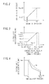
- Fig. 2 is a graph illustrating the relation between the amount of operation of the control lever or pedal in operation means such as the control lever device 50, the traveling pedal device 51, or the control lever device 52 for a crusher and the output pilot pressure (control pilot pressure).
- the control pilot pressure (tank pressure) is zero while the amount of operation is in a dead zone A1.
- the output pilot pressure increases from a minimum pilot pressure PminOP to a maximum pilot pressure PmaxOP until the amount of operation reaches A2.
- the control pilot pressure becomes constant at the maximum pressure PmaxOP.
- Fig. 3 is a graph illustrating a positive control function of the tilt control mechanisms 13 and 14, in which pressures inputted to the tilt control mechanisms 13 and 14 are plotted along the horizontal axis and tilting angles of the hydraulic pumps 11 and 12 controlled by the tilt control mechanisms 13 and 14 are plotted along the vertical axis.
- the minimum tilting angle qmin1 is set for the purpose of ensuring self-lubricating properties of the hydraulic pumps 11 and 12, while the maximum tilting angle qmax is determined by the specifications of the hydraulic pumps 11 and 12.
- Fig. 4 is a graph illustrating an absorption torque limiting control function of the tilt control mechanisms 13 and 14, in which average values of delivery pressure of the hydraulic pumps 11 and 12 are plotted along the horizontal axis and maximum tilting angles (maximum displacement volume) of each of the hydraulic pumps 11 and 12 are plotted along the vertical axis.
- the maximum tilting angle means a limiting value for a tilting angle.
- the maximum tilting angles of each of the hydraulic pumps 11 and 12 are maximum at qmax (q1max, q2max) until the average value of delivery pressure of the hydraulic pumps 11 and 12 reaches Pa.
- Pmax is a relief pressure of a main relief valve (not shown) connected to delivery hydraulic lines of the hydraulic pumps 11 and 12.
- the tilt control mechanisms 13 and 14 control the tilting angles of the hydraulic pumps 11 and 12 in such a manner that the tilting angles of the hydraulic pumps 11 and 12 become equal to the tilting angle based on the positive control function.
- the tilt control mechanisms 13 and 14 control the tilting angles of the hydraulic pumps 11 and 12 in such a manner that the tilting angles are limited to that maximum tilting angle.
- the total absorption torque of the hydraulic pumps 11 and 12 is controlled so as not to exceed a torque curve Tn shown in Fig. 4 .
- the torque curve Tn in Fig. 4 indicates a maximum output torque and thereabouts in a regulation area of the engine 10. Consequently, it is possible to prevent engine stall caused by overloading of the engine 10.
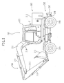
- Fig. 5 is a side view of a wheel excavator which carries thereon the hydraulic drive system associated with this embodiment.
- the wheel excavator 201 includes a lower travel structure 202, an upper swing structure 203 mounted rotatably on the lower travel structure 202, and a front working device 204.
- the lower travel structure 202 includes front wheels 205 and rear wheels 206, the rear wheels 206 being driven by the hydraulic motor 32 shown in Fig. 1 .
- the upper swing structure 203 includes a so-called cabin-type cab 209 and an outer cover 210 which covers the greater part of the upper swinging structure 203 other than the cab 209.
- the engine 10 and the hydraulic pumps 21 and 22 which are shown in Fig. 1 are mounted inside the outer cover 210.
- the front working device 204 includes a boom 211, an arm 212 connected to the boom 211 pivotably, and a bucket 213 connected to the arm 212 pivotably.
- the boom 211, arm 212 and bucket 213 are actuated by a boom cylinder 214, arm cylinder 215 and bucket cylinder 216, respectively.
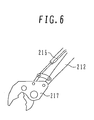
- Fig. 6 illustrates a part of the front working device 204 which is equipped with a crusher 217 instead of the bucket 213 as an working device attachment.
- the crusher 217 one of the working device attachments, is attached to a front end of the working device in place of the bucket 213, and it contains the actuator 218 shown in Fig. 1 .
- the actuator 218 shown in Fig. 1 requires a high flow rate (e.g., a flow rate corresponding to two pumps) and a high horsepower.
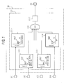
- Figs. 7 and 8 are functional block diagrams showing the details of arithmetic processing performed by the controller 100.
- the controller 100 includes, as shown in Fig. 7 , a first minimum pump tilt calculating section 111 which inputs detection signals from the traveling motor speed pickup 101, pressure sensor 102, signal receiving line 103a of the option selecting switch 103 and temperature sensor 104 and outputs a control signal for increasing the minimum tilting angle of the hydraulic pump 11 to the proportional solenoid valve 105; it also includes, as shown in Fig. 8 , a second minimum pump tilt calculating section 112 which inputs detection signals from the traveling motor speed pickup 101, signal receiving line 103a of the option selecting switch 103, and temperature sensor 104 and outputs a control signal for increasing the minimum tilting angle of the hydraulic pump 12 to the proportional solenoid valve 106.
- the first minimum pump tilt calculating section 111 includes a minimum tilt calculator 111a which utilizes vehicle speeds, a minimum tilt calculator 111b which utilizes the amounts of travel operation, a minimum tilt calculator 111c which utilizes mode switching signals, a minimum tilt calculator 111d which utilizes oil temperatures, a maximum value selector 111e, and a control signal generator 111f.
- the minimum tilt calculator 111a utilizing vehicle speed inputs the number of revolutions of the hydraulic motor 32 from the traveling motor speed pickup 101 as vehicle speed information, then refers to a table stored in memory beforehand for that information, and calculates a minimum tilting angle q1mina of the hydraulic pump 11 corresponding to the vehicle speed detected at that moment.
- the relation between vehicle speeds and the minimum tilting angles q1mina is set in the table stored in memory in such a manner that, during the period up to V1 indicating low vehicle speeds, the minimum tilting angle q1mina takes the same constant value as the minimum tilting angle q1min1 shown in Fig.
- the minimum tilting angle q1mina increases from q1min1 to q1min2, and when the vehicle speed becomes as high as V2 or more, the minimum tilting angle q1mina becomes constant at q1min2.
- the minimum tilt calculator 111b utilizing the amounts of travel operation inputs from the pressure sensor 102 a pilot pressure of the signal hydraulic line 72 as information on the amount of operation (amount of depression) of the traveling pedal 51a, then refers to a table stored in memory beforehand for that information, and calculates a minimum tilting angle q1minb of the hydraulic pump 11 corresponding to the amount of operation of the pedal detected at that moment.
- a table stored in memory as shown in Fig.
- the relation between the amounts of operation of the pedal and the minimum tilting angles q1minb is set in such a manner that, during the period up to A1 indicating small amounts of pedal operation, the minimum tilting angle q1minb takes the same constant value as the minimum tilting angle q1min1 set in the tilt control mechanism 13 and shown in Fig. 3 , while as the amount of pedal operation increases from A1 to A2, the minimum tilting angle q1minb increases from q1min1 to q1min2, and when the amount of pedal operation becomes greater than A2, the minimum tilting angle q1minb becomes constant at q1min2.
- the minimum tilt calculator 111c utilizing mode switching signals inputs a mode switching signal (option switching signal) from the signal receiving line 103a of the option selecting switch 103, then refers to a table stored in memory beforehand for that signal, and calculates a minimum tilting angle q1minc of the hydraulic pump 11 corresponding to the mode switching signal information.
- the relation between the mode switching signals and the minimum tilting angles q1minc is set in such a manner that when the signal of the option selecting switch 103 is OFF, the minimum tilting angle q1minc takes the same value as the minimum tilting angle q1min1 set in the tilt control mechanism 13 and shown in Fig. 3 , while the minimum tilting angle q1minc becomes qlmin2 with the signal of the option selecting switch 103 being ON.
- the minimum tilt calculator 111d utilizing oil temperature inputs oil temperature information of the hydraulic oil tank 42 from the temperature sensor 104, then refers to a table stored in memory in advance for that information, and calculates a minimum tilting angle q1mind of the hydraulic pump 11 corresponding to the oil temperature detected at that moment.
- the relation between oil temperatures and the minimum tilting angles q1mind is set in such a manner that: while the oil temperature stays below T1, an upper limit of a normal temperature range, the minimum tilting angle q1mind takes the same constant value as the minimum tilting angle q1min1 set in the tilt control mechanism 13 and shown in Fig.
- the maximum value selector 111e inputs the minimum tilting angles q1mina, q1minb, q1minc, and q1mind of the hydraulic pump 11 calculated respectively in the minimum tilt calculator 111a utilizing vehicle speeds, in the minimum tilt calculator 111b utilizing the amounts of travel operation, in the minimum tilt calculator 111c utilizing mode switching signals and in the minimum tilt calculator 111d utilizing oil temperatures, then selects q1minx as a maximum value of those tilting angles and outputs it to the control signal generator 111f.
- Fig. 9 is a functional block diagram showing the details of arithmetic processing performed by the control signal generator 111f.
- the control signal generator 111f includes a control pressure calculator 151, a control current calculator 152 and an amplifier 153.
- the control pressure calculator 151 inputs a maximum value q1minx, then refers to a table stored in memory beforehand for that information, and calculates a corresponding target control pressure P1CO.
- Such a relation between the maximum value q1minx and the target control pressure P1CO as shown in Fig. 9 is set in the table stored in memory.
- This relation is an inverse function of the relation between control pilot pressures and tilting angles of the hydraulic pumps 11 and 12 to be controlled, as shown in Fig. 3 .
- the control current calculator 152 inputs the target control pressure P1CO, then refers to a table stored in memory beforehand for that information, and calculates a target control current I1CO corresponding to the target control pressure P1CO input at that moment.
- the relation between the target control pressures P1CO and the target control currents I1CO is set in such a manner that the target control current I1CO increases as the target control pressure P1CO increases.
- the amplifier 153 amplifies the target control current I1CO into a control current I1C and outputs this amplified current to the solenoid 105a of the proportional solenoid valve 105.
- the proportional solenoid valve 105 operates with the control current I1C inputted to the solenoid 105a and outputs a corresponding control pressure P1C.
- the control pressure P1C corresponds to the target control pressure P1CO calculated by the control pressure calculator 151 at the time of the control pressure outputting.
- the second minimum pump tilt calculating section 112 includes a minimum tilt calculator 112a which utilizes vehicle speeds, a minimum tilt calculator 112c which utilizes mode switching signals, a minimum tilt calculator 112d which utilizes oil temperatures, a maximum value selector 112e, and a control signal generator 112f.
- the minimum tilt calculator 112a utilizing vehicle speeds inputs the number of revolutions of the hydraulic motor 32 from the traveling motor speed pickup 101 as vehicle speed information, then refers to a table stored in memory beforehand for that information, and calculates a minimum tilting angle q2mina of the hydraulic pump 12 corresponding to vehicle speed information input at that moment.
- the relation between vehicle speeds and the minimum tilting angles q2mina is set in such a manner that: during the period up to V1 of low vehicle speeds, the minimum tilting angle q2mina takes the same constant value as the minimum tilting angle q2min1 set in the tilt control mechanism 14 and shown in Fig. 3 ; that it increases from q2min1 to q2min2 as the vehicle speed increases from V1 to V2; and that it becomes constant at q2min2 when the vehicle speed becomes greater than V2.
- the minimum tilting angle calculator 112c utilizing mode switching signals inputs a mode switching signal (option switching signal) from the signal receiving line 103a of the option selecting switch 103, then refers to a table stored in memory beforehand for that signal, and calculates a minimum tilting angle q2minc of the hydraulic pump 12 corresponding to information on the mode switching signal.
- the relation between the mode switching signals and the minimum tilting angles q2minc is set in such a manner that when the option selecting switch 103 is OFF, the minimum tilting angle q2minc takes the same value as the minimum tilting angle q2min1 set in the tilt control mechanism 14 and shown in Fig. 3 while the minimum tilting angle q2minc becomes q2min2 with the option selecting switch 103 being ON.
- the minimum tilting angle calculator 112d utilizing oil temperatures inputs oil temperature information of the hydraulic oil tank 42 from the temperature sensor 104, then refers to a table stored in memory beforehand for that information, and calculates a minimum tilting angle q2mind of the hydraulic pump 11 corresponding to the oil temperature information input at that moment.
- the relation between oil temperatures and the minimum tilting angles q1mind is set in such a manner that: during the period up to T1 of the lowest oil temperature, the minimum tilting angle q2mind takes the same constant value as the minimum tilting angle q2min1 set in the tilt control mechanism 14 and shown in Fig. 3 ; that it increases from q2min1 to q2min2 as the oil temperature increases from T1 to T2; and that it becomes constant at q2min2 when the oil temperature becomes greater than T2.
- the maximum value selector 112e inputs the minimum tilting angles q2mina, q2minc, and q2mind of the hydraulic pump 12 calculated respectively by the minimum tilt calculator 112a utilizing vehicle speeds, the minimum tilt calculator 112c utilizing mode switching signals and the minimum tilt calculator 112d utilizing oil temperatures, then selects the maximum value out of those values as q2miny and outputs it to the control signal generator 112f.
- Fig. 10 is a functional block diagram showing the details of arithmetic processing performed by the control signal generator 112f.
- the control signal generator 112f includes a control pressure calculator 161, a control current calculator 162, and an amplifier 163.
- the control pressure calculator 161 inputs a maximum value q2miny, then refers to a table stored in memory beforehand for that ionformation, and calculates a corresponding target control pressure P2CO.
- Such a relation between the maximum values q2miny and target control pressures P2CO as shown in Fig. 10 is set in the table stored in memory. This relation is an inverse function of the relation between control pilot pressures and tilting angles of each of the hydraulic pumps 11 and 12 to be controlled, as shown in Fig. 3 .
- the control current calculator 162 inputs the target control pressure P2CO, then refers to a table stored in memory beforehand for that information, and calculates a target control current I2CO corresponding to the target control pressure P2CO input at that moment.
- the relation between the target control pressures P2CO and the target control currents I2CO is set in the table stored in memory in such a manner that the target control current I2CO increases as the target control pressure P2CO increases.
- the amplifier 163 amplifies the target control current I2CO into a control current I2C and outputs the control current I2C to the solenoid 106a of the proportional solenoid valve 106.
- the proportional solenoid valve 106 operates with the control current I2C inputted to the solenoid 106a and outputs a corresponding control pressure P2C.
- the control pressure P2C corresponds to the target control pressure P2CO calculated by the control pressure calculator 161 at the time of the control pressure outputting.
- the traveling motor speed pickup 101, the pressure sensor 102 and the signal receiving line 103a of the option selecting switch 103 constitute first detection means for detecting an operation pattern corresponding to a rise in temperature of the working fluid out of the operation patterns related to the plural members to be operated 32, 214, 218, ....
- the controller 100, the proportional solenoid valves 105 and 106, the shuttle valves 109 and 110 and the tilt control mechanisms 13 and 14 constitute pump flow rate increasing means for increasing the minimum capacities of the hydraulic pumps 11 and 12 on the basis of the operation pattern detected by the first detection means and thereby increasing an average flow rate of the working fluid passing through the oil cooler (heat exchanger) 40.
- controller 100 the proportional solenoid valves 105 and 106, the shuttle valves 109 and 110, and the tilt control mechanisms 13 and 14 constitute pump flow rate increasing means for increasing the minimum capacity of at least one of the plural hydraulic pumps 11 and 12 (either the hydraulic pump 11 or 12) on the basis of the operation pattern detected by the first detection means and thereby increasing an average flow rate of the working fluid passing through the oil cooler (heat exchanger) 40.
- the traveling motor speed pickup 101 as the first detection means is for detecting, as an operation pattern corresponding to a rise in temperature of the working fluid, an operation pattern related to the first member to be operated (traveling motor 32) which is actuated by the hydraulic pump 12, one of the plural hydraulic motors 11 and 12.
- the pump flow rate increasing means described above is configured so as to increase not only the minimum capacity of the hydraulic pump 12, one of the above-mentioned hydraulic pumps, but also the minimum capacity of the hydraulic pump 11, the other of the above-mentioned hydraulic pumps, based on the operation pattern related to the first member to be operated (traveling motor 32); it may also be configured so as to increase only the minimum capacity of the hydraulic pump 11, the other of the foregoing hydraulic pumps.
- the pilot pressure outputted from the operation means is zero (tank pressure), and the pressures of each of the signal hydraulic lines 73 and 74 are also zero (tank pressure).
- the option selecting switch 103 is OFF (normal operation mode) in the normal operation, that is, it is in an unoperated state, so that the values of detection signals from each of the traveling motor speed pickup 101 and the pressure sensor 102 are also zero. Further, when the oil temperature in the hydraulic oil tank 42 is within its normal range, the detection signal from the temperature sensor 104 also takes a value proportional thereto.
- q1min1 and q2min1 are thus calculated as minimum tilting angles in the first and second minimum pump tilt calculating sections 111 and 112 of the controller 100, and corresponding control currents I1C and I2C are outputted to the proportional solenoid valves 105 and 106, which in turn output control pressures P1C and P2C corresponding to q1min1 and q2min1, respectively.
- the control pressures P1C and P2C correspond to the target control pressures P1min1 and P2min2, respectively, which are calculated in the control pressure calculators 151 and 161 shown in Figs. 9 and 10 .
- control pressures P1C and P2C are selected in the shuttle valves 109 and 110.
- the control pressures P1C and P2C thus selected are inputted to the tilt control mechanisms 13 and 14, whereby the tilting angles of the hydraulic pumps 11 and 12 are controlled so as to become q1min1 and q2min1, respectively.
- the control result obtained is the same as that obtained in the case where the pressures (zero) in the signal hydraulic lines 73 and 74 are inputted as pump command pressures to the tilt control mechanisms 13 and 14 (prior art).
- the value of a signal from the signal receiving line 103a of the option selecting switch 103 as well as the values of detection signals from the traveling motor speed pickup 101, pressure sensor 102 and temperature sensor 104, which are inputted to the controller 100 at this moment, are the same as the values in the unoperated state mentioned above, and pressures ( ⁇ P1P) corresponding to the target control pressures P1min1 and P2min1 are outputted to the signal hydraulic lines 107 and 108.
- the pump command pressure P1P is selected in the shuttle valve 109.
- the tilt of the hydraulic pump 11 is controlled by the above-mentioned positive flow rate control ( Fig. 3 ) and the absorption torque limiting control ( Fig. 4 ) on the basis of the pump command pressure P1P and an average delivery pressure value of the hydraulic pumps 11 and 12.
- q1min1 and q2min1 are calculated as minimum tilting angles in the first and second minimum pump tilt calculating sections 111 and 112 of the controller 100, and this is thus the same as in the above normal operation. That is, in the tilt control mechanism 14, the tilt of the hydraulic pump 12 is controlled by the foregoing positive flow rate control ( Fig. 3 ) and absorption torque limiting control ( Fig. 4 ) on the basis of the pump command pressure P2P and an average delivery pressure value of the hydraulic pumps 11 and 12.
- a high pilot pressure is outputted from the control lever device 51 to either the pilot line 51c or 51d, and the control valve 26 is switched over by that pilot pressure.
- that pressure is detected by the shuttle valve 61, further selected by the high pressure selecting valve block 64, and then outputted as the pump command pressure P2P to the signal hydraulic line 74.
- the pump command pressure P2P is compared with the control pressure P2C in the shuttle valve 110. Since the traveling pedal 51a is in full operation at this time, meaning P2P>P2C because P2P >P2min2, the pump command pressure P2P is selected in the shuttle valve 110 and is inputted to the tilt control mechanism 14.
- the tilt of the hydraulic pump 12 is controlled by the foregoing positive flow rate control ( Fig 3 ) and the absorption torque limiting control ( Fig. 4 ) on the basis of the pump command pressure P2P and an average delivery pressure value of the hydraulic pumps 11 and 12.
- the delivery pressure of the hydraulic pump 12 becomes a pressure higher than Pa in Fig. 4 .
- a target tilt attained by positive control of the pump command pressure P2P is, for example, qmax shown in Fig. 3
- the tilting angle of the hydraulic pump 12 is limited to a tilting angle smaller than qmax. Then, hydraulic fluid with a flow rate according to that tilting angle is fed from the hydraulic pump 12 to the traveling hydraulic motor 32, and the vehicle travels at a speed proportional to that flow rate.
- the tilting angle of the hydraulic pump 12 is controlled so as to become qmax by positive control, and a correspondingly large flow rate of hydraulic fluid is discharged from the hydraulic pump 12.
- the traveling hydraulic motor 32 rotates at high speed, and the vehicle runs at high speed.
- the value of a detection signal provided from the pressure sensor 102 out of the signals inputted at this time to the controller 100 becomes equal to or greater than A2 in Fig. 7 because the traveling pedal 51a is in a state of full operation.
- q1min2 is calculated as the minimum tilting angle q1minb.
- the maximum value selector 111e the q1min2 thus calculated is selected as q1minx and is outputted to the control signal generator 111f.
- a control current I1C corresponding to q1minx (q1min2) is outputted from the control signal generator 111f to the proportional solenoid valve 105, which in turn outputs a corresponding control pressure P1C to the control hydraulic line 107.
- the control pressure P1C corresponds to P1min2 which is calculated in the control pressure calculator 151 shown in Fig. 9 .
- the pressure in the signal hydraulic line 73 is a tank pressure.
- the control pressure P1C is selected in the shuttle valve 109 and is inputted to the tilt control mechanism 13.
- the tilting angle of the hydraulic pump 11 is controlled so as to become q1min2 corresponding to P1min2. That is, the minimum tilting angle of the hydraulic pump 11 increases from q1min1 to q1min2. This increases an average flow rate of hydraulic fluid which is returned to the tank 42 through the discharge line 43 and also increases an average heat discharge amount in the oil cooler 40, whereby the equilibrium temperature of the working fluid can be reduced.
- the traveling pedal 51a If the traveling pedal 51a is operated fully with the intention of climbing an ascending slope, then on the hydraulic pump 12 side, as is the case with high-speed traveling on a flat road, the pump command pressure P2P based on a high pilot pressure provided from the traveling pedal device 51 is selected in the shuttle valve 110 and is inputted to the tilt control mechanism 14.
- the tilt of the hydraulic pump 12 is controlled by both of the foregoing positive flow rate control ( Fig. 3 ) and absorption torque limiting control ( Fig. 4 ) on the basis of the pump command pressure P2P and an average delivery pressure value of the hydraulic pumps 11 and 12.
- the traveling load is high due to uphill traveling, and the delivery pressure of the hydraulic pump 12 is equal to or greater than Pa in Fig. 4 . Therefore, even if the target tilt based on positive control of the pump command pressure P2P is, for example, qmax in Fig. 3 , the tilting angle of the hydraulic pump 12 is limited to a tilting angle smaller than qmax. Hydraulic fluid with a flow rate according to that tilting angle is fed from the hydraulic pump 12 to the traveling hydraulic motor 32, so that the vehicle runs at low speed.
- q1min2 is calculated as the minimum tilting angle q1minb in the target tilt calculator 111b in the first minimum pump tilt calculating section 111 of the controller 100, which utilizes the amount of travel operation, and a corresponding control pressure is outputted from the proportional solenoid valve 105 to the signal hydraulic line 107.
- the control pressure P1C is selected in the shuttle valve 109 and is inputted to the tilt control mechanism 13, whereby the tilting angle of the hydraulic pump 11 is controlled so as to become q1min2. That is, also in this case, the minimum tilting angle of the hydraulic pump 11 increases from q1min1 to q1min2. This increases an average flow rate of the hydraulic fluid which is returned to the tank 42 through the discharge line 43 and also increases an average heat discharge amount in the oil cooler 40, whereby the equilibrium temperature of the working fluid can be reduced.
- a low pilot pressure is outputted from the traveling pedal device 51 to either the pilot line 51c or 51d, and the control valve 26 is switched over by the pilot pressure.
- that pressure is detected by the shuttle valve 61 and is further selected by the high pressure selecting valve block 64, and is outputted as the pump command pressure P2P to the signal hydraulic line 74.
- the value of a detection signal provided from the traveling motor speed pickup 101 out of the signals inputted to the controller 100 at this time may become equal to or greater than V2 in Fig. 8 due to downhill traveling.
- q2min2 is thus calculated as the minimum tilting angle q2mina in the target tilt calculator 112a in the second minimum pump tilt calculating section 112, which utilizes vehicle speed, and a control pressure P2C corresponding to that q2min2 is outputted to the signal hydraulic line 108.
- the control pressure P2C corresponds to P2min2 which is calculated in the control pressure calculator 161 shown in Fig. 10 .
- the control pressure P2C is selected in the shuttle valve 110 and is inputted to the tilt control mechanism 14, whereby the tilting angle of the hydraulic pump 12 is controlled so as to become the tilting angle q2min2. That is, the tilting angle of the hydraulic pump 12 increases to q2min2 from the tilting angle positively controlled with the pump command pressure P2P.
- a surplus flow amount of the hydraulic fluid discharged from the hydraulic pump 12 passes through a center bypass of the control valve 26 and returns to the tank 42 via the discharge line 43.
- q1min2 is calculated as the minimum tilting angle q1mina in the target tilt calculator 111a in the first minimum pump tilt calculating section 111 of the controller 100, which utilizes vehicle speed, and a corresponding control pressure P1C (equivalent to P1min2 calculated in the control pressure calculator 151 shown in Fig. 9 ) is outputted from the proportional solenoid valve 105 to the signal hydraulic line 107.
- the control pressure PIC is selected in the shuttle valve 109 and is inputted to the tilt control mechanism 13, whereby the tilting angle of the hydraulic pump 11 is controlled so as to become q1min2. That is, also on the hydraulic pump 11 side, the minimum tilting angle increases from q1min1 to q1min2.
- the following description is now provided about a case where the bucket 213 is replaced with the crusher 217 and a crushing operation is performed.
- the crushing operation performed using the crusher 217 is an operation with high frequency of loading in comparison with the standard operations.
- the mode switching signal turns from OFF to ON, and an ON signal is inputted to the controller 100 from the signal receiving line 103a.
- q1min2 and q2min2 are calculated as minimum tilting angles q1minc and q2minc, respectively, in accordance with the ON signal, and corresponding control pressures P1C and P2C are outputted to the signal hydraulic lines 107 and 108, respectively.
- q1min2 and q2min2 are calculated as minimum tilting angles q1mind and q2mind on the basis of a detection signal provided from the temperature sensor 104 of the hydraulic oil tank 42 in the oil-temperature-based target tilt calculators 111d and 112d in the first and second pump tilt calculating sections 111 and 112 of the controller 100, and corresponding control pressures P1C and P2C are outputted.
- the minimum tilting angles of each of the hydraulic pumps 11 and 12 increases from q1min1 to q1min2. This increases an average flow rate of the hydraulic fluid which is returned to the tank 42 via the discharge line 43 and also increases an average heat discharge amount in the oil cooler 40, whereby the equilibrium temperature of the working fluid can be reduced.
- the traveling system is constructed so as to operate with only the hydraulic fluid fed from the hydraulic pump 12 side, it may be constructed such that the hydraulic fluid from both hydraulic pumps 11 and 12 is merged and the resultant confluent flow is fed to the traveling system to drive the same system.
- the operation mode of performing crushing work by a crusher has been described as an operation mode with high loading frequency
- the operation mode in question may be a heavy excavation mode (power mode) in the case of a system having such operation modes as a heavy excavation mode (power mode) and a fine operation mode.
- signals provided from the traveling motor speed pickup 101, the pressure sensor 102, the signal receiving line 103a of the option selecting switch 103 and the temperature sensor 104 are inputted to the controller 100, and the minimum tilting angles of each of the hydraulic pumps 11 and 12 are increased to improve the cooling performance in both the case (pre-case) where a rise of the working fluid temperature is predicted and the case (post-case) where the working fluid temperature rose.
- a modification may be adopted wherein the minimum tilting angles of each of the hydraulic pumps 11 and 12 are increased only in the case (pre-case) where a rise of the working fluid temperature is predicted.
- a modification may be adopted wherein the minimum tilting angles of each of the hydraulic pumps 11 and 12 are increased only in the case (post-case) where the working fluid temperature rose. In this case, it is possible to obtain the other effects than (1) described above.
- the minimum tilting angles q1min2 and q2min2 calculated in the minimum tilt calculators 111a and 112a concerned which utilize the vehicle speed can be made larger, which accordingly leads to an improved performance and is thus effective.
Landscapes
- Engineering & Computer Science (AREA)
- General Engineering & Computer Science (AREA)
- Mining & Mineral Resources (AREA)
- Civil Engineering (AREA)
- Structural Engineering (AREA)
- Fluid Mechanics (AREA)
- Physics & Mathematics (AREA)
- Mechanical Engineering (AREA)
- Chemical & Material Sciences (AREA)
- Analytical Chemistry (AREA)
- Operation Control Of Excavators (AREA)
- Fluid-Pressure Circuits (AREA)
- Component Parts Of Construction Machinery (AREA)
Abstract
Description
- The present invention relates to a working fluid cooling control system for a construction machine comprising a variable displacement type hydraulic pump, plural members to be operated by the hydraulic pump, and a heat exchanger for cooling working fluid (working oil) as an operating medium.
- In a conventional construction machine, especially a conventional hydraulic excavator or the like, the specifications of a cooling system including a heat exchanger as a cooler for working fluid are optimized so as to ensure a heat balance of a prime mover, a hydraulic system, etc. on the basis of standard operations using a bucket. In this case, in the states of operations performed under severer conditions than in standard operations, such as, for example, a continuous high-load operation, an operation performed in a place of a very high ambient temperature such as in a tunnel, or an operation performed with the construction machine deteriorated, the heat balance is lost, which increases the temperature of the hydraulic system and adversely affects the machine lives of hydraulic devices.
- However, if the specifications of the cooling system are optimized beforehand so as to ensure a heat balance under severer conditions than in standard operations such as, for example, a continuous high-load operation, not only the problem of overengineering occurs relative to the standard operations most frequent in general use, but also it is uneconomical. If the capacity of the heat exchanger is increased as a countermeasure, the entire cooling system becomes larger in size, leading to an increase of cost and an increase in size of the construction machine concerned, or the problem may arise that the noise level becomes higher because the cooling air volume needs to be increased.
- In connection with such problems,
JP-A-2000-110560 - According to a technique disclosed in Japanese Utility Model Registration No.
2565113 - Patent Literature 1:
JP, A 2000-110560 - Patent Literature 2: Japanese Utility Model Registration No.
2565113 - However, basically in all of the above conventional techniques, after increase in temperature of the working fluid, the increased temperature is reduced by the cooler; thus, the influence of such an increase in temperature is unavoidable although the increase may be temporary. Consequently, the deterioration of sealing parts occurs due to a rise of the oil temperature, or the increase in wear of sliding parts occurs due to the lowering in viscosity of the working fluid, thus giving rise to the problem of failures of hydraulic devices or shortened machine lives thereof.
- In the conventional technique disclosed in
JP-A-2000-110560 - In the conventional technique disclosed in Japanese Utility Model Registration No.
2565113 - It is an object of the present invention to provide a working fluid cooling control system for a construction machine wherein the cooling performance is improved before a rise in temperature of working fluid to prevent a rise in temperature of the working fluid whereby reduced failures of hydraulic devices and improved machine lives thereof can be achieved and a worsening of noise and of fuel efficiency can further be prevented.
-
- (1) To achieve the above-mentioned object, the present invention provides a working fluid cooling control system for a construction machine having a variable displacement type hydraulic pump, a plurality of members to be operated by the hydraulic pump, and a heat exchanger for cooling a working fluid as an operating medium, wherein the capacity of the hydraulic pump is decreased to a preset minimum capacity when the plural members to be operated enter an unoperated state, the working fluid cooling control system comprising first detection means for detecting an operation pattern corresponding to a rise in temperature of the working fluid from among operation patterns associated with the plural members to be operated and pump flow rate increasing means which on the basis of the operation pattern detected by the first detection means increases the minimum capacity of the hydraulic pump to increase an average flow rate of the working fluid passing through the heat exchanger.
By thus providing the first detection means and the pump flow rate increasing means to detect an operation pattern corresponding to a rise in temperature of the working fluid, to increase the minimum capacity of the hydraulic pump, and to increase an average flow rate of the working fluid passing through the heat exchanger, it becomes possible to predict a temperature rise of the working fluid, increase an average heat discharge amount of the heat exchanger (improve the cooling performance) beforehand (before the temperature rise of the working fluid), and reduce an equilibrium temperature of the working fluid. As a result, it becomes possible to prevent the occurrence of a temperature rise of the working fluid, diminish failures of the hydraulic devices and improve the machine lives thereof. Moreover, since the cooling performance is improved by increasing the minimum capacity of the hydraulic pump to increase an average flow rate of the working fluid passing through the heat exchanger, a worsening of noise does not occur, and it is possible to minimize a worsening of fuel efficiency. - (2) In the above (1), the first detection means detects, as the operation pattern corresponding to a rise in temperature of the working fluid, an operation state of a member with high loading frequency out of the plural members to be operated.
Consequently, when the operation pattern corresponding to a rise in temperature of the working fluid airses during travel of the construction machine, it is detected, and this detection makes it possible to improve the cooling performance in advance. - (3) In the above (2), the first detection means detects, as the operation state of the to-be-operated member with high loading frequency, an operation signal of operation means for said member.
Consequently, when the operation pattern corresponding to a rise in temperature of the working fluid arises, for example, during the full operation of travel operation means, it is detected, and this detection makes it possible to improve the cooling performance in advance. - (4) In the above (2), the first detection means detects, as the operation state of the member with high loading frequency, an operation speed of said member.
Consequently, when the operation pattern corresponding to a rise in temperature of the working fluid airses, for example, during high-speed traveling, it is detected, and this detection makes it possible to improve the cooling performance in advance. - (5) In the above (1), the first detection means detects, as the operation pattern corresponding to a rise in temperature of the working fluid, an operation mode with high loading frequency from among operation modes associated with the plural members to be operated.
Consequently, when the operation mode corresponding to a rise in temperature of the working fluid, e.g., an operation mode using a crusher, arises, it is detected, and this detection makes it possible to improve the cooling performance in advance. - (6) In the above (5), the construction machine further has selector means for selecting an operation mode using such an attachment as a crusher or the like and other operation modes, and the first detection means detects the operation mode using a crusher as the operation mode with high loading frequency.
Consequently, when the operation mode using a crusher arises as the operation mode corresponding to a rise in temperature of the working fluid, it is detected, and this detection makes it possible to improve the cooling performance in advance. - (7) In the above (1), the working fluid cooling control system further comprises second detection means for detecting a temperature of the working fluid, and the pump flow rate increasing means increases the minimum capacity of the hydraulic pump on the basis of both the operation pattern detected by the first detection means and the temperature of the working fluid detected by the second detection means.
Consequently, even in the event the temperature of the working fluid should rise due to, for example, a worsening of the surrounding environment under the operation pattern not corresponding to a rise in temperature of the working fluid, it is possible to improve the cooling performance of the heat exchanger and thereby reduce the increased temperature of the working fluid. - (8) In the above (7), the pump flow rate increasing means comprises means for calculating a first minimum capacity on the basis of the operation pattern detected by the first detection means; means for calculating a second minimum capacity on the basis of the temperature of the working fluid detected by the second detection means; means for selecting the larger capacity of the first and second minimum capacities; and means for changing the minimum capacity of the hydraulic pump on the basis of the selected minimum capacity.
Consequently, the cooling performance of the heat exchanger is improved before a rise in temperature of the working fluid, whereby it is possible to prevent a rise in temperature of the working fluid. Besides, even in the event the temperature of the working fluid should rise due to, for example, a worsening of the surrounding environment under the operation pattern not corresponding to a rise in temperature of the working fluid, the cooling performance of the heat exchanger is improved; hence, it is possible to reduce the increased temperature of the working fluid. - (9) Further, to achieve the foregoing object, the present invention provides a construction machine comprising a plurality of variable displacement type hydraulic pumps; a plurality of members to be operated by the plural hydraulic pumps; and a heat exchanger for cooling a working fluid as an operating medium, the capacity of the plural hydraulic pumps being reduced to a preset minimum capacity when the plural members to be operated enter an unoperated state, characterized by further comprising first detection means for detecting an operation pattern corresponding to a rise in temperature of the working fluid from among operation patterns associated with the plural members to be operated; and pump flow rate increasing means which on the basis of the operation pattern detected by the first detection means increases the minimum capacity of at least one of the plural hydraulic pumps so as to increase an average flow rate of the working fluid passing through the heat exchanger.
Consequently, in the hydraulic system having plural hydraulic pumps, by the same effect as that described in the above (1), it becomes possible to predict a rise in temperature of the working fluid, increase an average heat discharge amount of the heat exchanger (improve the cooling performance) in advance (before the rise in temperature of the working fluid), and decrease the equilibrium temperature of the working fluid. As a result, it becomes possible to prevent the occurrence of a temperature rise of the working fluid, diminish failures of hydraulic devices and improve the machine lives thereof. Further, since the cooling performance is improved by increasing the minimum capacity of the hydraulic pumps and the average flow rate of the working fluid passing through the heat exchanger, neither a worsening of noise nor a worsening of fuel efficiency occurs. - (10) In the above (9), the first detection means detects, as the operation pattern corresponding to a rise in temperature of the working fluid, an operation pattern associated with a first to-be-operated member operated by one hydraulic pump out of the plural hydraulic pumps, and the pump flow rate increasing means increases the minimum capacity of the other hydraulic pump(s) than said one hydraulic pump on the basis of the operation pattern associated with the first to-be-operated member.
- Consequently, when plural hydraulic pumps are used, it is possible to utilize an idle hydraulic pump(s) (the other hydraulic pump(s) than said one hydraulic pump) effectively, thereby improve the cooling performance of the heat exchanger, and prevent the occurrence of a temperature rise of the working fluid.
- According to the present invention it is possible to improve the cooling performance before a rise in temperature of the working fluid, thereby prevent the occurrence of a temperature rise of the working fluid, diminish failures of hydraulic devices, and improve the machine lives thereof. Moreover, since the cooling performance is improved by increasing the minimum capacity of a hydraulic pump(s) to increase an average flow rate of the working fluid passing through the heat exchanger, a worsening of noise does not occur and it is possible to minimize a worsening of fuel efficiency.
-
-
Fig. 1 illustrates a working fluid cooling control system for a construction machine according to an embodiment of the present invention, together with a hydraulic drive system. -
Fig. 2 illustrates the relation between the amounts of operation of a control lever or a pedal in operation means such as a control lever device, a traveling pedal device or a control lever device for a crusher and output pilot pressures (control pilot pressures). -
Fig.3 illustrates a positive control function of a tilt control mechanism. -
Fig. 4 illustrates an absorption torque limiting control function of the tilt control mechanism. -
Fig. 5 is a side view of a wheel excavator which carries thereon the hydraulic drive system associated with the embodiment. -
Fig. 6 illustrates a part of a front working device equipped with a crusher instead of a bucket as an working device attachment. -
Fig. 7 is a functional block diagram showing the details of arithmetic processing performed by a first minimum pump tilt calculating section of a controller. -
Fig. 8 is a functional block diagram showing the details of arithmetic processing performed by a second minimum pump tilt calculating section of the controller. -
Fig. 9 is a functional block diagram showing the details of arithmetic processing performed by a control signal generator in the first minimum pump tilt calculating section. -
Fig. 10 is a functional block diagram showing the details of arithmetic processing performed by a control signal generator in the second minimum pump tilt calculating section. -
- 10
- engine
- 11, 12
- hydraulic pump
- 13, 14
- tilt control mechanism
- 20, 21
- control valve group
- 22-24, 26-28
- control valve
- 32
- hydraulic motor
- 40
- oil cooler
- 41
- cooling fan
- 42
- hydraulic oil tank
- 50
- control lever device
- 51
- traveling pedal device
- 52
- control lever device
- 60, 61, 62
- shuttle valve
- 63, 64
- high pressure selecting valve block
- 100
- controller
- 101
- traveling motor speed pickup
- 102
- pressure sensor
- 103
- option selecting switch
- 104
- temperature sensor
- 105, 106
- proportional solenoid valve
- 109, 110
- shuttle valve
- 202
- lower travel structure
- 203
- upper swing structure
- 204
- front working device
- 207
- blade
- 208
- blade cylinder
- 211
- boom
- 212
- arm
- 213
- bucket
- 214
- boom cylinder
- 215
- arm cylinder
- 216
- bucket cylinder
- 217
- crusher
- 218
- actuator
- An embodiment of the present invention will be described hereinunder with reference to the drawings.
-
Fig. 1 illustrates a working fluid cooling control system for a construction machine according to an embodiment of the present invention, together with a hydraulic drive system (hydraulic system). - In
Fig. 1 , the hydraulic drive system includes two variable displacement typehydraulic pumps control valve groups tilt control mechanisms 13 and 14, respectively, for controlling respective tilting angles. - The
control valve group 20 is made up of plural control valves including center bypasstype control valves hydraulic pump 11. Thecontrol valve group 21 is made up of plural control valves including center bypasstype control valves hydraulic pump 12. The control valves, which are connected to various hydraulic actuators constituting members to be operated, control the flow of hydraulic fluid discharged from thehydraulic pumps - The
control valve 22 of thecontrol valve group 20 is for a boom, for example, and connected to a boom cylinder 214 (seeFig. 5 ) as a corresponding hydraulic actuator. - The
control valve 26 of thecontrol valve group 20 is for traveling and connected to ahydraulic motor 32 as a corresponding hydraulic actuator. Acounterbalance valve 34 and a pair of crossover relief valves 33 are provided on a line which connects thecontrol valve 26 and thehydraulic motor 32. - The control valve 23 of the
control valve group 20 and the control valve 27 of thecontrol valve group 21 are spare control valves, which are used with operating machine attachments (hereinafter referred to as option attachments) other than a bucket attached. Examples of option attachments include various attachments including a crusher and a breaker. When such option attachments are used, the hydraulic actuators of each option attachment are connected to the control valves 23 and 27 with use ofconnectors Fig. 1 shows a case where ahydraulic cylinder 218 of a crusher is connected to the control valves 23 and 27. The crusher is an attachment which requires a high flow rate and a large horsepower. Anoption selecting switch 103 is provided for the use of such an attachment requiring a high flow rate and a large horsepower, e.g., a crusher. A confluence switching valve 36 is provided on the actuator line side of the control valves 23 and 27. Theoption selecting switch 103 is operation-mode switching means. When theoption selecting switch 103 is pushed, a crushing mode is selected, and a mode selecting controller (not shown) transmits a switching signal to a confluence switching valve 36, thereby switching the confluence switching valve 36 to a confluence position (open position). As a result, delivery pressures from thehydraulic pumps hydraulic cylinder 218 of the crusher. At the same time, a signal is fed from the mode selecting controller to a fuel injection volume controller (not shown), so that the number of revolutions of anengine 10 increases. - A
control lever device 50 is provided as operation means for theboom control valve 22. A travelingpedal device 51 is provided as operation means for the travelingcontrol valve 26. Further, acontrol lever device 52 for a crusher is provided as operation means for the spare control valves 23 and 27 which are used for the crusher. - The
control lever device 50 has acontrol lever 50a and apilot valve 50b and generates a control pilot pressure in either apilot line control lever 50a. Thecontrol valve 22 is switched over by the control pilot pressure. - The traveling
pedal device 51 has a travelingpedal 51a and apilot valve 51b and generates a control pilot pressure in either apilot line pedal 51a. Thecontrol valve 26 is switched over by the control pilot pressure. - The
control lever device 52 for a crusher has a control lever 52a and a pilot valve 52b and generates a control pilot pressure in either apilot line - Also, control lever devices similar to the
control lever device 50 are provided for theother control valves 24 ... and 28 .... - A
shuttle valve 60 as means for detecting the operative amount of the boom is provided in thepilot lines control lever device 50 is outputted. Ashuttle valve 61 as means for detecting the amount of travel operation is provided in thepilot lines pedal device 51 is outputted. Further, ashuttle valve 62 as means for detecting the operative amount of the crusher is provided in thepilot lines control lever device 52 is outputted. Similar shuttle valves are also provided in other control lever devices. - The pilot pressures detected by the
shuttle valves control valve group 20 out of the above-mentionedshuttle valves valve block 63 through a signalhydraulic line 71. Then, in the high pressure selectingvalve block 63, the highest pressure is selected from among those pressures and the highest pressure thus selected is outputted as a positively-controlled pump command pressure P1P to the signal hydraulic line 73. - Likewise, the pilot pressures detected by the
shuttle valves 26, 27 ... associated with thecontrol valve group 21 are conducted to a high pressure selectingvalve block 64 through a signalhydraulic line 72. In the high pressure selectingvalve block 64, the highest pressure is selected from among those pressures, and the highest pressure thus selected is outputted as a positively-controlled pump command pressure P2P to a signalhydraulic line 74. - A tilt control mechanism 13 inputs the positive control command pressure P1P from a signal
hydraulic line 75 and controls the tilting angle (displacement volume) of thehydraulic pump 11 in such a manner that the tilting angle in question increases with a rise of the command pressure. Moreover, the tilt control mechanism 13 inputs the delivery pressure of thehydraulic pump 11 associated with itself from a signalhydraulic line 76 and further inputs the delivery pressure of the otherhydraulic pump 12 from a signalhydraulic line 77. When an average delivery pressure of thehydraulic pumps hydraulic pump 11 with a rise of the average delivery pressure and controls the tilting angle of thehydraulic pump 11 so as to keep the absorption torques of thehydraulic pumps - Likewise, the
tilt control mechanism 14 inputs the positive control command pressure P2P from a signal hydraulic line 78 and controls the tilting angle (displacement volume) of thehydraulic pump 12 in such a manner that the tilting angle in question increases with a rise of the command pressure. Moreover, thetilt control mechanism 14 inputs the delivery pressure of thehydraulic pump 12 associated with itself from a signalhydraulic line 79 and further inputs the delivery pressure of the otherhydraulic pump 11 from a signalhydraulic line 80. When an average delivery pressure of thehydraulic pumps tilt control mechanism 14 decreases the tilting angle of thehydraulic pump 12 with a rise of the average delivery pressure and controls the tilting angle of thehydraulic pump 12 so as to keep the absorption torques of thehydraulic pumps - The hydraulic oil (hydraulic working fluid) discharged from the
hydraulic pumps control valve groups hydraulic oil tank 42 from adischarge line 43 directly or as return oil from hydraulic actuators such as thehydraulic motor 32 and aboom cylinder 218. In thedischarge line 43 is disposed an oil cooler 40 for cooling the hydraulic oil which is returned to thehydraulic oil tank 42. The oil cooler 40 is cooled by a coolingfan 41. The coolingfan 41 is rotated by theengine 10 together with thehydraulic pumps - The working fluid cooling control system of this embodiment is provided in the hydraulic drive system constructed as above. This system includes a traveling
motor speed pickup 101, apressure sensor 102, asignal receiving line 103a of theoption selecting switch 103, and atemperature sensor 104. The travelingmotor speed pickup 101, thepressure sensor 102 and thesignal receiving line 103a of theoption selecting switch 103 are provided as means for detecting operation patterns in which the temperature of the working fluid in the circuit increases. The travelingmotor speed pickup 101 detects the number of revolutions of thehydraulic motor 32 and thereby detects the vehicle speed. Thepressure sensor 102 detects a pilot pressure of the signalhydraulic line 72 and thereby detects the amount of operation (amount of depression) of the travelingpedal 51a. Thesignal receiving line 103a of theoption selecting switch 103 receives a mode switching signal of theoption selecting switch 103 and thereby detects an operation pattern in which an attachment (e.g., crusher) which requires a high flow rate and a large horsepower is used. Thetemperature sensor 104 is provided in thehydraulic oil tank 42 to detect the temperature of the working fluid (oil temperature) in the circuit. - The working fluid cooling control system of this embodiment further includes a
controller 100,proportional solenoid valves shuttle valves 109 and 110. Thecontroller 100 inputs detection signals from the travelingmotor speed pickup 101, thepressure sensor 102, thesignal receiving line 103a of theoption selecting switch 103 and thetemperature sensor 104, then performs predetermined processing and outputs control currents I1c and I2c (control signals) tosolenoids proportional solenoid valves proportional solenoid valves hydraulic lines shuttle valve 109 is disposed between the signal hydraulic line 73 on the output side of the high pressure selectingvalve block 63 and the signalhydraulic line 107 and selects either the positively-controlled pump command pressure P1P selected by the high pressure selectingvalve block 63 or the control pressure P1C outputted from theproportional solenoid valve 105 whichever is at a higher level, and then outputs the thus-selected pressure to the signalhydraulic line 75 in the tilt control mechanism 13. - Likewise, the shuttle valve 110 is disposed between the signal
hydraulic line 74 on the output side of the high pressure selectingvalve block 64 and the signalhydraulic line 108. The shuttle valve 110 selects either the positive control command pressure P2P selected by the high pressure selectingvalve block 64 or the control pressure P2C outputted from theproportional solenoid valve 106 whichever is at a higher level and then outputs the thus-selected pressure to the signal hydraulic line 78 in thetilt control mechanism 14. -
Fig. 2 is a graph illustrating the relation between the amount of operation of the control lever or pedal in operation means such as thecontrol lever device 50, the travelingpedal device 51, or thecontrol lever device 52 for a crusher and the output pilot pressure (control pilot pressure). - In
Fig. 2 , the control pilot pressure (tank pressure) is zero while the amount of operation is in a dead zone A1. When the amount of operation exceeds A1, the output pilot pressure increases from a minimum pilot pressure PminOP to a maximum pilot pressure PmaxOP until the amount of operation reaches A2. When the amount of operation exceeds A2, the control pilot pressure becomes constant at the maximum pressure PmaxOP. -
Fig. 3 is a graph illustrating a positive control function of thetilt control mechanisms 13 and 14, in which pressures inputted to thetilt control mechanisms 13 and 14 are plotted along the horizontal axis and tilting angles of thehydraulic pumps tilt control mechanisms 13 and 14 are plotted along the vertical axis. - In
Fig. 3 , until the input pressure reaches Pmin1 (P1min1, P2min1), the tilting angles of each of thehydraulic pumps - The minimum tilting angle qmin1 is set for the purpose of ensuring self-lubricating properties of the
hydraulic pumps hydraulic pumps -
Fig. 4 is a graph illustrating an absorption torque limiting control function of thetilt control mechanisms 13 and 14, in which average values of delivery pressure of thehydraulic pumps hydraulic pumps - In
Fig. 4 , the maximum tilting angles of each of thehydraulic pumps hydraulic pumps hydraulic pumps hydraulic pumps hydraulic pumps - When a target tilting angle based on the positive control function shown in
Fig. 3 is smaller than the maximum tilting angle based on the absorption torque limiting control function shown inFig. 4 and corresponding to an average pump pressure value obtained at the time of the detection, thetilt control mechanisms 13 and 14 control the tilting angles of thehydraulic pumps hydraulic pumps tilt control mechanisms 13 and 14 control the tilting angles of thehydraulic pumps hydraulic pumps Fig. 4 . The torque curve Tn inFig. 4 indicates a maximum output torque and thereabouts in a regulation area of theengine 10. Consequently, it is possible to prevent engine stall caused by overloading of theengine 10. - If the vertical axis in
Fig. 4 is replaced with pump flow rate, the illustrated control becomes horsepower control and Tn becomes a horsepower curve. The control using the horizontal axis inFig. 4 as average values of delivery pressures of thehydraulic pumps -
Fig. 5 is a side view of a wheel excavator which carries thereon the hydraulic drive system associated with this embodiment. - In
Fig. 5 , thewheel excavator 201 includes alower travel structure 202, anupper swing structure 203 mounted rotatably on thelower travel structure 202, and afront working device 204. Thelower travel structure 202 includesfront wheels 205 andrear wheels 206, therear wheels 206 being driven by thehydraulic motor 32 shown inFig. 1 . - The
upper swing structure 203 includes a so-called cabin-type cab 209 and anouter cover 210 which covers the greater part of theupper swinging structure 203 other than thecab 209. Theengine 10 and thehydraulic pumps Fig. 1 are mounted inside theouter cover 210. - The
front working device 204 includes aboom 211, anarm 212 connected to theboom 211 pivotably, and abucket 213 connected to thearm 212 pivotably. Theboom 211,arm 212 andbucket 213 are actuated by aboom cylinder 214,arm cylinder 215 andbucket cylinder 216, respectively. -
Fig. 6 illustrates a part of thefront working device 204 which is equipped with acrusher 217 instead of thebucket 213 as an working device attachment. - The
crusher 217, one of the working device attachments, is attached to a front end of the working device in place of thebucket 213, and it contains theactuator 218 shown inFig. 1 . In comparison with thebucket cylinder 216, theactuator 218 shown inFig. 1 requires a high flow rate (e.g., a flow rate corresponding to two pumps) and a high horsepower. -
Figs. 7 and8 are functional block diagrams showing the details of arithmetic processing performed by thecontroller 100. - The
controller 100 includes, as shown inFig. 7 , a first minimum pumptilt calculating section 111 which inputs detection signals from the travelingmotor speed pickup 101,pressure sensor 102,signal receiving line 103a of theoption selecting switch 103 andtemperature sensor 104 and outputs a control signal for increasing the minimum tilting angle of thehydraulic pump 11 to theproportional solenoid valve 105; it also includes, as shown inFig. 8 , a second minimum pumptilt calculating section 112 which inputs detection signals from the travelingmotor speed pickup 101,signal receiving line 103a of theoption selecting switch 103, andtemperature sensor 104 and outputs a control signal for increasing the minimum tilting angle of thehydraulic pump 12 to theproportional solenoid valve 106. - In
Fig. 7 , the first minimum pumptilt calculating section 111 includes a minimum tilt calculator 111a which utilizes vehicle speeds, a minimum tilt calculator 111b which utilizes the amounts of travel operation, aminimum tilt calculator 111c which utilizes mode switching signals, aminimum tilt calculator 111d which utilizes oil temperatures, amaximum value selector 111e, and acontrol signal generator 111f. - The minimum tilt calculator 111a utilizing vehicle speed inputs the number of revolutions of the
hydraulic motor 32 from the travelingmotor speed pickup 101 as vehicle speed information, then refers to a table stored in memory beforehand for that information, and calculates a minimum tilting angle q1mina of thehydraulic pump 11 corresponding to the vehicle speed detected at that moment. As shown inFig. 7 , the relation between vehicle speeds and the minimum tilting angles q1mina is set in the table stored in memory in such a manner that, during the period up to V1 indicating low vehicle speeds, the minimum tilting angle q1mina takes the same constant value as the minimum tilting angle q1min1 shown inFig. 3 , which is set in the tilt control mechanism 13, while with an increase of the vehicle speed from V1 to V2, the minimum tilting angle q1mina increases from q1min1 to q1min2, and when the vehicle speed becomes as high as V2 or more, the minimum tilting angle q1mina becomes constant at q1min2. - The minimum tilt calculator 111b utilizing the amounts of travel operation inputs from the pressure sensor 102 a pilot pressure of the signal
hydraulic line 72 as information on the amount of operation (amount of depression) of the travelingpedal 51a, then refers to a table stored in memory beforehand for that information, and calculates a minimum tilting angle q1minb of thehydraulic pump 11 corresponding to the amount of operation of the pedal detected at that moment.
In the table stored in memory, as shown inFig. 7 , the relation between the amounts of operation of the pedal and the minimum tilting angles q1minb is set in such a manner that, during the period up to A1 indicating small amounts of pedal operation, the minimum tilting angle q1minb takes the same constant value as the minimum tilting angle q1min1 set in the tilt control mechanism 13 and shown inFig. 3 , while as the amount of pedal operation increases from A1 to A2, the minimum tilting angle q1minb increases from q1min1 to q1min2, and when the amount of pedal operation becomes greater than A2, the minimum tilting angle q1minb becomes constant at q1min2. - The
minimum tilt calculator 111c utilizing mode switching signals inputs a mode switching signal (option switching signal) from thesignal receiving line 103a of theoption selecting switch 103, then refers to a table stored in memory beforehand for that signal, and calculates a minimum tilting angle q1minc of thehydraulic pump 11 corresponding to the mode switching signal information. In the table stored in memory, as shown inFig. 7 , the relation between the mode switching signals and the minimum tilting angles q1minc is set in such a manner that when the signal of theoption selecting switch 103 is OFF, the minimum tilting angle q1minc takes the same value as the minimum tilting angle q1min1 set in the tilt control mechanism 13 and shown inFig. 3 , while the minimum tilting angle q1minc becomes qlmin2 with the signal of theoption selecting switch 103 being ON. - The
minimum tilt calculator 111d utilizing oil temperature inputs oil temperature information of thehydraulic oil tank 42 from thetemperature sensor 104, then refers to a table stored in memory in advance for that information, and calculates a minimum tilting angle q1mind of thehydraulic pump 11 corresponding to the oil temperature detected at that moment. In the table stored in memory, as shown inFig. 7 , the relation between oil temperatures and the minimum tilting angles q1mind is set in such a manner that: while the oil temperature stays below T1, an upper limit of a normal temperature range, the minimum tilting angle q1mind takes the same constant value as the minimum tilting angle q1min1 set in the tilt control mechanism 13 and shown inFig. 3 ; that the minimum tilting angle q1mind increases from q1min1 to q1min2 as the oil temperature increases from T1 to T2; and that the minimum tilting angle q1mind becomes constant at q1min2 when the oil temperature becomes greater than T2. - The
maximum value selector 111e inputs the minimum tilting angles q1mina, q1minb, q1minc, and q1mind of thehydraulic pump 11 calculated respectively in the minimum tilt calculator 111a utilizing vehicle speeds, in the minimum tilt calculator 111b utilizing the amounts of travel operation, in theminimum tilt calculator 111c utilizing mode switching signals and in theminimum tilt calculator 111d utilizing oil temperatures, then selects q1minx as a maximum value of those tilting angles and outputs it to thecontrol signal generator 111f. -
Fig. 9 is a functional block diagram showing the details of arithmetic processing performed by thecontrol signal generator 111f. Thecontrol signal generator 111f includes acontrol pressure calculator 151, a controlcurrent calculator 152 and anamplifier 153. Thecontrol pressure calculator 151 inputs a maximum value q1minx, then refers to a table stored in memory beforehand for that information, and calculates a corresponding target control pressure P1CO. Such a relation between the maximum value q1minx and the target control pressure P1CO as shown inFig. 9 is set in the table stored in memory. This relation is an inverse function of the relation between control pilot pressures and tilting angles of thehydraulic pumps Fig. 3 . - The control
current calculator 152 inputs the target control pressure P1CO, then refers to a table stored in memory beforehand for that information, and calculates a target control current I1CO corresponding to the target control pressure P1CO input at that moment. In the table stored in memory, the relation between the target control pressures P1CO and the target control currents I1CO is set in such a manner that the target control current I1CO increases as the target control pressure P1CO increases. - The
amplifier 153 amplifies the target control current I1CO into a control current I1C and outputs this amplified current to thesolenoid 105a of theproportional solenoid valve 105. - The
proportional solenoid valve 105 operates with the control current I1C inputted to thesolenoid 105a and outputs a corresponding control pressure P1C. The control pressure P1C corresponds to the target control pressure P1CO calculated by thecontrol pressure calculator 151 at the time of the control pressure outputting. - In
Fig. 8 , the second minimum pumptilt calculating section 112 includes a minimum tilt calculator 112a which utilizes vehicle speeds, aminimum tilt calculator 112c which utilizes mode switching signals, aminimum tilt calculator 112d which utilizes oil temperatures, amaximum value selector 112e, and acontrol signal generator 112f. - The minimum tilt calculator 112a utilizing vehicle speeds inputs the number of revolutions of the
hydraulic motor 32 from the travelingmotor speed pickup 101 as vehicle speed information, then refers to a table stored in memory beforehand for that information, and calculates a minimum tilting angle q2mina of thehydraulic pump 12 corresponding to vehicle speed information input at that moment. In the table stored in memory, as shown inFig. 8 , the relation between vehicle speeds and the minimum tilting angles q2mina is set in such a manner that: during the period up to V1 of low vehicle speeds, the minimum tilting angle q2mina takes the same constant value as the minimum tilting angle q2min1 set in thetilt control mechanism 14 and shown inFig. 3 ; that it increases from q2min1 to q2min2 as the vehicle speed increases from V1 to V2; and that it becomes constant at q2min2 when the vehicle speed becomes greater than V2. - The minimum
tilting angle calculator 112c utilizing mode switching signals inputs a mode switching signal (option switching signal) from thesignal receiving line 103a of theoption selecting switch 103, then refers to a table stored in memory beforehand for that signal, and calculates a minimum tilting angle q2minc of thehydraulic pump 12 corresponding to information on the mode switching signal. In the table stored in memory, as shown inFig. 8 , the relation between the mode switching signals and the minimum tilting angles q2minc is set in such a manner that when theoption selecting switch 103 is OFF, the minimum tilting angle q2minc takes the same value as the minimum tilting angle q2min1 set in thetilt control mechanism 14 and shown inFig. 3 while the minimum tilting angle q2minc becomes q2min2 with theoption selecting switch 103 being ON. - The minimum
tilting angle calculator 112d utilizing oil temperatures inputs oil temperature information of thehydraulic oil tank 42 from thetemperature sensor 104, then refers to a table stored in memory beforehand for that information, and calculates a minimum tilting angle q2mind of thehydraulic pump 11 corresponding to the oil temperature information input at that moment. In the table stored in memory, as shown inFig. 8 , the relation between oil temperatures and the minimum tilting angles q1mind is set in such a manner that: during the period up to T1 of the lowest oil temperature, the minimum tilting angle q2mind takes the same constant value as the minimum tilting angle q2min1 set in thetilt control mechanism 14 and shown inFig. 3 ; that it increases from q2min1 to q2min2 as the oil temperature increases from T1 to T2; and that it becomes constant at q2min2 when the oil temperature becomes greater than T2. - The
maximum value selector 112e inputs the minimum tilting angles q2mina, q2minc, and q2mind of thehydraulic pump 12 calculated respectively by the minimum tilt calculator 112a utilizing vehicle speeds, theminimum tilt calculator 112c utilizing mode switching signals and theminimum tilt calculator 112d utilizing oil temperatures, then selects the maximum value out of those values as q2miny and outputs it to thecontrol signal generator 112f. -
Fig. 10 is a functional block diagram showing the details of arithmetic processing performed by thecontrol signal generator 112f. Thecontrol signal generator 112f includes acontrol pressure calculator 161, a controlcurrent calculator 162, and anamplifier 163. Thecontrol pressure calculator 161 inputs a maximum value q2miny, then refers to a table stored in memory beforehand for that ionformation, and calculates a corresponding target control pressure P2CO. Such a relation between the maximum values q2miny and target control pressures P2CO as shown inFig. 10 is set in the table stored in memory. This relation is an inverse function of the relation between control pilot pressures and tilting angles of each of thehydraulic pumps Fig. 3 . - The control
current calculator 162 inputs the target control pressure P2CO, then refers to a table stored in memory beforehand for that information, and calculates a target control current I2CO corresponding to the target control pressure P2CO input at that moment. The relation between the target control pressures P2CO and the target control currents I2CO is set in the table stored in memory in such a manner that the target control current I2CO increases as the target control pressure P2CO increases. - The
amplifier 163 amplifies the target control current I2CO into a control current I2C and outputs the control current I2C to thesolenoid 106a of theproportional solenoid valve 106. - The
proportional solenoid valve 106 operates with the control current I2C inputted to thesolenoid 106a and outputs a corresponding control pressure P2C. The control pressure P2C corresponds to the target control pressure P2CO calculated by thecontrol pressure calculator 161 at the time of the control pressure outputting. - In the above construction, the traveling
motor speed pickup 101, thepressure sensor 102 and thesignal receiving line 103a of theoption selecting switch 103 constitute first detection means for detecting an operation pattern corresponding to a rise in temperature of the working fluid out of the operation patterns related to the plural members to be operated 32, 214, 218, .... Thecontroller 100, theproportional solenoid valves shuttle valves 109 and 110 and thetilt control mechanisms 13 and 14 constitute pump flow rate increasing means for increasing the minimum capacities of thehydraulic pumps - Further, the
controller 100, theproportional solenoid valves shuttle valves 109 and 110, and thetilt control mechanisms 13 and 14 constitute pump flow rate increasing means for increasing the minimum capacity of at least one of the pluralhydraulic pumps 11 and 12 (either thehydraulic pump 11 or 12) on the basis of the operation pattern detected by the first detection means and thereby increasing an average flow rate of the working fluid passing through the oil cooler (heat exchanger) 40. - The traveling
motor speed pickup 101 as the first detection means is for detecting, as an operation pattern corresponding to a rise in temperature of the working fluid, an operation pattern related to the first member to be operated (traveling motor 32) which is actuated by thehydraulic pump 12, one of the pluralhydraulic motors hydraulic pump 12, one of the above-mentioned hydraulic pumps, but also the minimum capacity of thehydraulic pump 11, the other of the above-mentioned hydraulic pumps, based on the operation pattern related to the first member to be operated (traveling motor 32); it may also be configured so as to increase only the minimum capacity of thehydraulic pump 11, the other of the foregoing hydraulic pumps. - The following description is now provided about the operation of this embodiment.
- First, a description will be given about a normal operating performed in a state in which the
front working device 204 is equipped with thebucket 213. - When all of the operation means, including the
control lever device 50 and the travelingpedal device 51, are in an unoperated state during the normal operation, the pilot pressure outputted from the operation means is zero (tank pressure), and the pressures of each of the signalhydraulic lines 73 and 74 are also zero (tank pressure). - On the other hand, the
option selecting switch 103 is OFF (normal operation mode) in the normal operation, that is, it is in an unoperated state, so that the values of detection signals from each of the travelingmotor speed pickup 101 and thepressure sensor 102 are also zero. Further, when the oil temperature in thehydraulic oil tank 42 is within its normal range, the detection signal from thetemperature sensor 104 also takes a value proportional thereto. In this case, q1min1 and q2min1 are thus calculated as minimum tilting angles in the first and second minimum pumptilt calculating sections controller 100, and corresponding control currents I1C and I2C are outputted to theproportional solenoid valves control pressure calculators Figs. 9 and10 . As a result, control pressures P1C and P2C are selected in theshuttle valves 109 and 110. The control pressures P1C and P2C thus selected are inputted to thetilt control mechanisms 13 and 14, whereby the tilting angles of thehydraulic pumps hydraulic lines 73 and 74 are inputted as pump command pressures to the tilt control mechanisms 13 and 14 (prior art). - In this state, when, for example, the operator operates the
control lever 50a of thecontrol lever device 50 with the intention of moving theboom 211, a control pilot pressure is generated in either thepilot line control valve 22 is switched over by that pilot pressure. At the same time, that pressure is detected by theshuttle valve 60 and is further selected by the high pressure selectingvalve block 63, then is outputted as the pump command pressure P1P to the signal hydraulic line 73. - On the other hand, the value of a signal from the
signal receiving line 103a of theoption selecting switch 103 as well as the values of detection signals from the travelingmotor speed pickup 101,pressure sensor 102 andtemperature sensor 104, which are inputted to thecontroller 100 at this moment, are the same as the values in the unoperated state mentioned above, and pressures (<P1P) corresponding to the target control pressures P1min1 and P2min1 are outputted to the signalhydraulic lines shuttle valve 109. In the tilt control mechanism 13, the tilt of thehydraulic pump 11 is controlled by the above-mentioned positive flow rate control (Fig. 3 ) and the absorption torque limiting control (Fig. 4 ) on the basis of the pump command pressure P1P and an average delivery pressure value of thehydraulic pumps - The operations performed in the above normal operation are also true of the case where other operation means associated with the
control valve group 20 is operated and of the case where operation means associated with thecontrol valve group 21 other than the travelingpedal device 51 is operated. - The following description is now provided about operations which are performed during travel by operating the traveling pedal 51a of the traveling
pedal device 51. - In low-speed traveling (vehicle speed < V1) involving a small amount of operation of the traveling
pedal 51a and a low vehicle speed, q1min1 and q2min1 are calculated as minimum tilting angles in the first and second minimum pumptilt calculating sections controller 100, and this is thus the same as in the above normal operation. That is, in thetilt control mechanism 14, the tilt of thehydraulic pump 12 is controlled by the foregoing positive flow rate control (Fig. 3 ) and absorption torque limiting control (Fig. 4 ) on the basis of the pump command pressure P2P and an average delivery pressure value of thehydraulic pumps - When the traveling
pedal 51a is operated fully with the intention of high-speed running on a flat road, a high pilot pressure is outputted from thecontrol lever device 51 to either thepilot line control valve 26 is switched over by that pilot pressure. At the same time, that pressure is detected by theshuttle valve 61, further selected by the high pressure selectingvalve block 64, and then outputted as the pump command pressure P2P to the signalhydraulic line 74. The pump command pressure P2P is compared with the control pressure P2C in the shuttle valve 110. Since the travelingpedal 51a is in full operation at this time, meaning P2P>P2C because P2P >P2min2, the pump command pressure P2P is selected in the shuttle valve 110 and is inputted to thetilt control mechanism 14. - In the
tilt control mechanism 14, the tilt of thehydraulic pump 12 is controlled by the foregoing positive flow rate control (Fig 3 ) and the absorption torque limiting control (Fig. 4 ) on the basis of the pump command pressure P2P and an average delivery pressure value of thehydraulic pumps - During acceleration with a high traveling load, for example, the delivery pressure of the
hydraulic pump 12 becomes a pressure higher than Pa inFig. 4 . Even if a target tilt attained by positive control of the pump command pressure P2P is, for example, qmax shown inFig. 3 , the tilting angle of thehydraulic pump 12 is limited to a tilting angle smaller than qmax. Then, hydraulic fluid with a flow rate according to that tilting angle is fed from thehydraulic pump 12 to the travelinghydraulic motor 32, and the vehicle travels at a speed proportional to that flow rate. - In steady traveling after the end of the acceleration, if the delivery pressure of the
hydraulic pump 12 drops to a lower level near Pa inFig. 4 , the maximum tilting angle based on the absorption torque limiting control also becomes the same qmax as the target tilt attained by positive control of the pump command pressure P2p. Therefore, the tilting angle of thehydraulic pump 12 is controlled so as to become qmax by positive control, and a correspondingly large flow rate of hydraulic fluid is discharged from thehydraulic pump 12. As a result, the travelinghydraulic motor 32 rotates at high speed, and the vehicle runs at high speed. - On the other hand, the value of a detection signal provided from the
pressure sensor 102 out of the signals inputted at this time to thecontroller 100 becomes equal to or greater than A2 inFig. 7 because the travelingpedal 51a is in a state of full operation. In the target tilt calculator 111b in the first minimum pumptilt calculating section 111, which utilizes the amount of travel operation, q1min2 is calculated as the minimum tilting angle q1minb. Then, in themaximum value selector 111e, the q1min2 thus calculated is selected as q1minx and is outputted to thecontrol signal generator 111f. A control current I1C corresponding to q1minx (q1min2) is outputted from thecontrol signal generator 111f to theproportional solenoid valve 105, which in turn outputs a corresponding control pressure P1C to the controlhydraulic line 107. The control pressure P1C corresponds to P1min2 which is calculated in thecontrol pressure calculator 151 shown inFig. 9 . At this time, the pressure in the signal hydraulic line 73 is a tank pressure. - As a result, the control pressure P1C is selected in the
shuttle valve 109 and is inputted to the tilt control mechanism 13. The tilting angle of thehydraulic pump 11 is controlled so as to become q1min2 corresponding to P1min2. That is, the minimum tilting angle of thehydraulic pump 11 increases from q1min1 to q1min2. This increases an average flow rate of hydraulic fluid which is returned to thetank 42 through thedischarge line 43 and also increases an average heat discharge amount in the oil cooler 40, whereby the equilibrium temperature of the working fluid can be reduced. - If the traveling
pedal 51a is operated fully with the intention of climbing an ascending slope, then on thehydraulic pump 12 side, as is the case with high-speed traveling on a flat road, the pump command pressure P2P based on a high pilot pressure provided from the travelingpedal device 51 is selected in the shuttle valve 110 and is inputted to thetilt control mechanism 14. In thetilt control mechanism 14, the tilt of thehydraulic pump 12 is controlled by both of the foregoing positive flow rate control (Fig. 3 ) and absorption torque limiting control (Fig. 4 ) on the basis of the pump command pressure P2P and an average delivery pressure value of thehydraulic pumps - At this time, the traveling load is high due to uphill traveling, and the delivery pressure of the
hydraulic pump 12 is equal to or greater than Pa inFig. 4 . Therefore, even if the target tilt based on positive control of the pump command pressure P2P is, for example, qmax inFig. 3 , the tilting angle of thehydraulic pump 12 is limited to a tilting angle smaller than qmax. Hydraulic fluid with a flow rate according to that tilting angle is fed from thehydraulic pump 12 to the travelinghydraulic motor 32, so that the vehicle runs at low speed. - At this time, on the
hydraulic pump 11 side, as is the case with high-speed traveling on a flat road, q1min2 is calculated as the minimum tilting angle q1minb in the target tilt calculator 111b in the first minimum pumptilt calculating section 111 of thecontroller 100, which utilizes the amount of travel operation, and a corresponding control pressure is outputted from theproportional solenoid valve 105 to the signalhydraulic line 107. As a result, the control pressure P1C is selected in theshuttle valve 109 and is inputted to the tilt control mechanism 13, whereby the tilting angle of thehydraulic pump 11 is controlled so as to become q1min2. That is, also in this case, the minimum tilting angle of thehydraulic pump 11 increases from q1min1 to q1min2. This increases an average flow rate of the hydraulic fluid which is returned to thetank 42 through thedischarge line 43 and also increases an average heat discharge amount in the oil cooler 40, whereby the equilibrium temperature of the working fluid can be reduced. - If the traveling
pedal 51a is operated lightly with the intention of traveling on a downward slope, a low pilot pressure is outputted from the travelingpedal device 51 to either thepilot line control valve 26 is switched over by the pilot pressure. At the same time, that pressure is detected by theshuttle valve 61 and is further selected by the high pressure selectingvalve block 64, and is outputted as the pump command pressure P2P to the signalhydraulic line 74. - On the other hand, the value of a detection signal provided from the traveling
motor speed pickup 101 out of the signals inputted to thecontroller 100 at this time may become equal to or greater than V2 inFig. 8 due to downhill traveling. In this case, q2min2 is thus calculated as the minimum tilting angle q2mina in the target tilt calculator 112a in the second minimum pumptilt calculating section 112, which utilizes vehicle speed, and a control pressure P2C corresponding to that q2min2 is outputted to the signalhydraulic line 108. The control pressure P2C corresponds to P2min2 which is calculated in thecontrol pressure calculator 161 shown inFig. 10 . - As a result, when the amount of traveling pedal operation is small such that P2P is less than P2C (P2P<P2C), the control pressure P2C is selected in the shuttle valve 110 and is inputted to the
tilt control mechanism 14, whereby the tilting angle of thehydraulic pump 12 is controlled so as to become the tilting angle q2min2. That is, the tilting angle of thehydraulic pump 12 increases to q2min2 from the tilting angle positively controlled with the pump command pressure P2P. In this case, a surplus flow amount of the hydraulic fluid discharged from thehydraulic pump 12 passes through a center bypass of thecontrol valve 26 and returns to thetank 42 via thedischarge line 43. - Also on the
hydraulic pump 11 side, when the vehicle speed is V2 or higher, as is the case with thehydraulic pump 12 side, q1min2 is calculated as the minimum tilting angle q1mina in the target tilt calculator 111a in the first minimum pumptilt calculating section 111 of thecontroller 100, which utilizes vehicle speed, and a corresponding control pressure P1C (equivalent to P1min2 calculated in thecontrol pressure calculator 151 shown inFig. 9 ) is outputted from theproportional solenoid valve 105 to the signalhydraulic line 107. As a result, the control pressure PIC is selected in theshuttle valve 109 and is inputted to the tilt control mechanism 13, whereby the tilting angle of thehydraulic pump 11 is controlled so as to become q1min2. That is, also on thehydraulic pump 11 side, the minimum tilting angle increases from q1min1 to q1min2. - Thus, in certain operational conditions during downhill traveling, not only the tilting angle of the
hydraulic pump 11 but also that of thehydraulic pump 12 increases greater than the tilting angle specified by the pump command pressure P2P, with the result that an average flow rate of the hydraulic fluid which is returned to thetank 42 via thedischarge line 43 increases not only by the hydraulic oil fed from thehydraulic pump 11 side but also by the hydraulic oil fed from thehydraulic pump 12 side, and an average heat discharge amount in the oil cooler 40 increases. Consequently, the equilibrium temperature of the working fluid can be reduced. - Although in connection with the hydraulic pump 11 a description has been given above about the case where the vehicle speed is V2 or more, also in the case where the speed is between V1 and V2, the minimum tilting angle calculated in each of the target tilt calculators 111a and 112a, which utilize the vehicle speed, increases larger than qmin1 in the range between qmin1 and qmin2. Accordingly, the effect of on an improved cooling performance as a result of the increase in tilting angles (increase in delivery flow rates) of the
hydraulic pumps - The following description is now provided about a case where the
bucket 213 is replaced with thecrusher 217 and a crushing operation is performed. The crushing operation performed using thecrusher 217 is an operation with high frequency of loading in comparison with the standard operations. - When the operator pushes the
option selecting switch 103 with the intention of performing crushing work such as, for example, a demolition operation, the mode switching signal turns from OFF to ON, and an ON signal is inputted to thecontroller 100 from thesignal receiving line 103a. In theminimum tilt calculators tilt calculating sections controller 100, which utilize the mode switching signal, q1min2 and q2min2 are calculated as minimum tilting angles q1minc and q2minc, respectively, in accordance with the ON signal, and corresponding control pressures P1C and P2C are outputted to the signalhydraulic lines - As a result, in an unoperated state in which none of the operation means, including the
control lever device 52 for a crusher, are in operation, such as the time of a shift from one crushing operation to another, the minimum tilting angles of each of thehydraulic pumps tank 42 via thedischarge line 43 and also increases an average heat discharge amount in the oil cooler 40, whereby the equilibrium temperature of the working fluid can be reduced. - Next, a description will be given below about what operation is to be performed if the oil temperature in the
hydraulic oil tank 42 should rise beyond the normal temperature range during the normal operation. - On occasion, the working fluid temperature in the hydraulic system circuit rises due to operation in a place of an extremely high ambient temperature or due to deterioration of the machine concerned regardless of the normal operation.
- When the oil temperature rises to, say, T2 or more during the normal operation, q1min2 and q2min2 are calculated as minimum tilting angles q1mind and q2mind on the basis of a detection signal provided from the
temperature sensor 104 of thehydraulic oil tank 42 in the oil-temperature-basedtarget tilt calculators tilt calculating sections controller 100, and corresponding control pressures P1C and P2C are outputted. - As a result, in an unoperated state in which none of the operation means are in operation, the minimum tilting angles of each of the
hydraulic pumps tank 42 via thedischarge line 43 and also increases an average heat discharge amount in the oil cooler 40, whereby the equilibrium temperature of the working fluid can be reduced. - The following effects are obtained according to this embodiment.
- (1) Signals provided from the traveling
motor speed pickup 101, thepressure sensor 102, and thesignal receiving line 103a of theoption selecting switch 103 are inputted to thecontroller 100. During travel with high loading frequency in comparison with the standard operations or the crushing operation (e.g., demolition operation) using a crusher, such operation patterns are detected, and the minimum tilting angles of each of thehydraulic pumps - (2) A detection signal provided from the
temperature sensor 104 is inputted to thecontroller 100. Even in the event the working fluid temperature in the hydraulic system circuit should rise due to, for example, operation in a place of a very high ambient temperature or deterioration of the machine regardless of the normal operation, such states are detected, and the minimum tilting angles of each of thehydraulic pumps - (3) As a result of the above (1) and (2), the frequency of the working fluid temperature rising beyond its normal range diminishes to a great extent, so that the deterioration of sealing parts due to a rise in oil temperature and the increase in wear of sliding parts due to the lowering in viscosity of the working fluid are diminished. Accordingly, reduced failures of the hydraulic devices and extended machine lives thereof can be acheived.
- (4) Since the capacity of each of the
hydraulic pumps - (5) Since the
controller 100 determines whether it is necessary or not to improve the cooling performance of the oil cooler (heat exchanger) 40 and then performs control on the basis of the determination, both operator's judgment and manual operation become unnecessary. This contributes to increased ease of use (increased operability). - (6) Since, during travel, the hydraulic pump 11 (an idle hydraulic pump) not directly associated with traveling is utilized and its minimum tilting angle is increased to increase the average flow rate of the working fluid in the oil cooler (heat exchanger) 40 beforehand, it is possible to improve the cooling performance in a more effective manner and prevent a rise in temperature of the working fluid.
- Although in the above embodiment the description has been given about the hydraulic drive system having two hydraulic pumps (11 and 12), only one hydraulic pump may be used. In this case, it is also possible to obtain the above effects (1) to (5).
- Although in the above embodiment the traveling system is constructed so as to operate with only the hydraulic fluid fed from the
hydraulic pump 12 side, it may be constructed such that the hydraulic fluid from bothhydraulic pumps - Although in the above embodiment the operation mode of performing crushing work by a crusher has been described as an operation mode with high loading frequency, the operation mode in question may be a heavy excavation mode (power mode) in the case of a system having such operation modes as a heavy excavation mode (power mode) and a fine operation mode.
- According to the construction described above, signals provided from the traveling
motor speed pickup 101, thepressure sensor 102, thesignal receiving line 103a of theoption selecting switch 103 and thetemperature sensor 104 are inputted to thecontroller 100, and the minimum tilting angles of each of thehydraulic pumps hydraulic pumps hydraulic pumps - Further, although in the above embodiment the minimum capacities (minimum tilting angles) of both
hydraulic pumps motor speed pickup 101, a modification may be adopted wherein the minimum capacity (minimum tilting angle) of only thehydraulic pump 11 that is the other hydraulic pump than the one associated with traveling is increased. Also in this case it is possible to obtain the other effects than (2) described above. - In the above embodiment, the minimum tilting angles calculated in the minimum tilt calculator 111a utilizing the vehicle speed; in the minimum tilt calculator 111b utilizing the amount of travel operation; in the
minimum tilt calculator 111c utilizing a mode switching signal; in theminimum tilt calculator 111d utilizing the oil temperature; in the minimum tilt calculator 112a utilizing the vehicle speed; in theminimum tilt calculator 112c utilizing a mode switching signal; and in theminimum tilt calculator 112d utilizing the oil temperature, with all the calculators being parts of thecontroller 100, are made the same values as the minimum tilting angles q1min2 and q2min2 when an operation pattern corresponding to a rise in temperature of the working fluid is detected; however, they may be made different arbitrarily according to the characteristics of various operation patterns. For example, when the vehicle speed becomes high on a descent, a rise in temperature caused by relief in the crossover relief valve 33 noticeably occurs in many cases. In this case, the minimum tilting angles q1min2 and q2min2 calculated in the minimum tilt calculators 111a and 112a concerned which utilize the vehicle speed can be made larger, which accordingly leads to an improved performance and is thus effective.
Claims (10)
- A working fluid cooling control system for a construction machine having variable displacement type hydraulic pumps (11 and 12), a plurality of members (32, 214, 215, 216, and 218) to be operated by said hydraulic pump, and a heat exchanger (40) for cooling a working fluid as an operating medium, the capacity of said hydraulic pump being decreased to a preset minimum capacity when said plural members to be operated enter an unoperated state, wherein the working fluid cooling control system comprises:first detection means (101, 102, and 103a) for detecting an operation pattern corresponding to a rise in temperature of said working fluid from among operation patterns associated with said plural members to be operated; andpump flow rate increasing means (13, 14, 100, 105, 106, 109, and 110) which on the basis of the operation pattern detected by said first detection means increase the minimum capacity of said hydraulic pump so as to increase an average flow rate of the working fluid passing through said heat exchanger.
- The working fluid cooling control system for a construction machine according to claim 1, wherein said first detection means (101, 102, and 103a) detect, as the operation pattern corresponding to a rise in temperature of the working fluid, operation states of members with higher loading frequency (32 and 218) out of said plural members to be operated (32, 214, 215, 216, and 218).
- The working fluid cooling control system for a construction machine according to claim 2, wherein said first detection means (102) detects, as the operation state of said member with higher loading frequency (32), an operation signal of operation means (51) for said member.
- The working fluid cooling control system for a construction machine according to claim 2, wherein said first detection means (101) detects, as the operation state of said member with higher loading frequency (32), an operation speed of said member.
- The working fluid cooling control system for a construction machine according to claim 1, wherein said first detection means (103a) detects, as the operation pattern corresponding to a rise in temperature of said working fluid, an operation mode with higher loading frequency from among operation modes associated with said plural members (32, 214, 215, 216, and 218) to be operated.
- The working fluid cooling control system for a construction machine according to claim 5, wherein:said construction machine (201) further has selector means (103) for selecting an operation mode using an attachment (217) such as a crusher or the like and other operation modes, andsaid first detection means (103a) detects said operation mode using a crusher as said operation mode with higher loading frequency.
- The working fluid cooling control system for a construction machine according to claim 1, wherein the construction machine further comprises second detection means (104) for detecting a temperature of said working fluid, and
wherein said pump flow rate increasing means (13, 14, 100, 105, 106, 109, and 110) increase the minimum capacities of said hydraulic pumps (11 and 12) on the basis of both the operation pattern detected by said first detection means (101, 102, and 103a) and the temperature of the working fluid detected by said second detection means. - The construction machine according to claim 7, wherein said pump flow rate increasing means (13, 14, 100, 105, 106, 109, and 110) comprise:means (111a, 111b, and 111c; 112a and 112c) for calculating a first minimum capacity on the basis of the operation pattern detected by said first detection means (101, 102, and 103a);means (111d; 112d) for calculating a second minimum capacity on the basis of the temperature of the working fluid detected by said second detection means (104);means (111e; 112e) for selecting the larger capacity of said first and second minimum capacities; andmeans (13, 14, 105, 106, 109, 110, and 111f; 112f) for changing the minimum capacities of said hydraulic pumps (11 and 12) on the basis of the selected minimum capacity.
- A construction machine comprising a plurality of variable displacement type hydraulic pumps (11 and 12), a plurality of members (32, 214, 215, 216, and 218) to be operated by each of said plural hydraulic pumps, and a heat exchanger for cooling a working fluid as an operating medium, the capacities of said plural hydraulic pumps being reduced to a preset minimum capacity when said plural members to be operated enter an unoperated state, characterized by further comprising:first detection means (101, 102, and 103a) for detecting an operation pattern corresponding to a rise in temperature of said working fluid from among operation patterns associated with said plural members to be operated; andpump flow rate increasing means (13, 14, 100, 105, 106, 109, and 110) which on the basis of the operation pattern detected by said first detection means increase the minimum capacity of at least one of sad plural hydraulic pumps to increase an average flow rate of the working fluid passing through said heat exchanger.
- The construction machine according to claim 9, wherein:said first detection means (101, 102, and 103a) detect, as the operation pattern corresponding to a rise in temperature of said working fluid, an operation pattern associated with a first to-be-operated member (32) operated by one hydraulic pump (12) out of said plural hydraulic pumps (11 and 12), andsaid pump flow rate increasing means (13, 14, 100, 105, 106, 109,and 110) increase the minimum capacity of the other hydraulic pump (11) than said one hydraulic pump on the basis of the operation pattern associated with said first to-be-operated member.
Applications Claiming Priority (2)
| Application Number | Priority Date | Filing Date | Title |
|---|---|---|---|
| JP2005271412A JP4331151B2 (en) | 2005-09-20 | 2005-09-20 | Working fluid cooling control system for construction machinery |
| PCT/JP2006/318271 WO2007034734A1 (en) | 2005-09-20 | 2006-09-14 | Working fluid cooling control system of construction machine |
Publications (3)
| Publication Number | Publication Date |
|---|---|
| EP1927762A1 true EP1927762A1 (en) | 2008-06-04 |
| EP1927762A4 EP1927762A4 (en) | 2012-01-04 |
| EP1927762B1 EP1927762B1 (en) | 2018-03-21 |
Family
ID=37888779
Family Applications (1)
| Application Number | Title | Priority Date | Filing Date |
|---|---|---|---|
| EP06797983.1A Not-in-force EP1927762B1 (en) | 2005-09-20 | 2006-09-14 | Working fluid cooling control system of construction machine |
Country Status (6)
| Country | Link |
|---|---|
| US (1) | US8127541B2 (en) |
| EP (1) | EP1927762B1 (en) |
| JP (1) | JP4331151B2 (en) |
| KR (1) | KR101169703B1 (en) |
| CN (1) | CN101268286B (en) |
| WO (1) | WO2007034734A1 (en) |
Cited By (1)
| Publication number | Priority date | Publication date | Assignee | Title |
|---|---|---|---|---|
| EP2767739A1 (en) * | 2013-02-19 | 2014-08-20 | Dana Rexroth Transmission Systems S.r.l. | Power-split transmission for a vehicle propulsion system, method for controlling the transmission |
Families Citing this family (22)
| Publication number | Priority date | Publication date | Assignee | Title |
|---|---|---|---|---|
| JP2007177798A (en) * | 2005-12-26 | 2007-07-12 | Kobelco Cranes Co Ltd | Hydraulic traveling device for work vehicle |
| JP5067290B2 (en) * | 2008-07-15 | 2012-11-07 | コベルコ建機株式会社 | Work machine |
| US20100106344A1 (en) * | 2008-10-27 | 2010-04-29 | Edwards Dean B | Unmanned land vehicle having universal interfaces for attachments and autonomous operation capabilities and method of operation thereof |
| KR101657248B1 (en) * | 2009-11-18 | 2016-09-19 | 볼보 컨스트럭션 이큅먼트 에이비 | hydraulic oil cooling system of construction equipment |
| CN101974926A (en) * | 2010-09-29 | 2011-02-16 | 三一重机有限公司 | Oil returning system capable of automatically controlling hydraulic oil temperature used for excavator |
| AU2012202213B2 (en) * | 2011-04-14 | 2014-11-27 | Joy Global Surface Mining Inc | Swing automation for rope shovel |
| KR101975062B1 (en) * | 2011-12-27 | 2019-05-03 | 두산인프라코어 주식회사 | Hydraulic system of construction machinery |
| US9518594B1 (en) | 2012-04-30 | 2016-12-13 | The Boeing Company | Hydraulic fluid heat dissipation control assembly and method |
| CN102734273A (en) * | 2012-06-15 | 2012-10-17 | 三一重机有限公司 | Oil temperature control device, hydraulic system and oil temperature control method thereof |
| CN103161784B (en) * | 2013-03-07 | 2015-10-14 | 三一重机有限公司 | Hydraulic system and engineering machinery |
| US9416799B2 (en) * | 2013-03-15 | 2016-08-16 | Eaton Corporation | Methods and systems for flow sharing in a hydraulic transformer system with multiple pumps |
| CN103591087B (en) * | 2013-11-18 | 2017-10-27 | 中联重科股份有限公司 | Temperature control device and control method for pumping hydraulic system, construction machinery |
| US9846002B2 (en) | 2014-12-18 | 2017-12-19 | GM Global Technology Operations LLC | Method and apparatus to determine an effective temperature of coolant fluid for a heat generating device |
| US9840143B1 (en) | 2015-05-20 | 2017-12-12 | Hydro-Gear Limited Partnership | Cooling pump assembly and cooling system for utility vehicle |
| US10358040B1 (en) | 2015-06-01 | 2019-07-23 | Hydro-Gear Limited Partnership | Drive assembly and system for utility vehicle |
| CN105201963A (en) * | 2015-10-26 | 2015-12-30 | 北京市三一重机有限公司 | Hydraulic oil temperature control system and rotary drilling rig |
| JP6511387B2 (en) * | 2015-11-25 | 2019-05-15 | 日立建機株式会社 | Control device for construction machine |
| CN106269048B (en) * | 2016-08-24 | 2018-11-13 | 南通诺佰恩化工科技有限公司 | Control three-roller grinding temperature system and device |
| KR101886103B1 (en) * | 2016-09-26 | 2018-08-07 | 현대자동차 주식회사 | Oil pressure supply system of automatic transmission for hybrid vehicle |
| JP2018168977A (en) * | 2017-03-30 | 2018-11-01 | 川崎重工業株式会社 | Hydraulic system |
| CN109798283A (en) * | 2019-01-21 | 2019-05-24 | 江苏大学 | One kind remotely controlling more relay protective scheme function central pumping stations |
| WO2026160829A1 (en) * | 2025-01-24 | 2026-07-30 | 에이치디건설기계 주식회사 | Hydraulic device for construction machinery and control method thereof |
Family Cites Families (13)
| Publication number | Priority date | Publication date | Assignee | Title |
|---|---|---|---|---|
| JPS6044604A (en) * | 1983-08-22 | 1985-03-09 | Hitachi Constr Mach Co Ltd | Hydraulic circuit of hydraulic operating machine |
| JPS62188806A (en) * | 1986-02-15 | 1987-08-18 | Yutani Juko Kk | Cooling system of hydraulic working machine |
| JPH0613882B2 (en) * | 1986-02-21 | 1994-02-23 | 油谷重工株式会社 | Hydraulic oil cooling device for hydraulic work machine |
| JP2565113Y2 (en) | 1991-11-22 | 1998-03-11 | 株式会社タダノ | Oil cooler for work equipment |
| JPH0623874U (en) * | 1991-12-09 | 1994-03-29 | 株式会社ユニシアジェックス | Power steering device |
| JPH0623874A (en) | 1992-07-04 | 1994-02-01 | Tdk Corp | Method of manufacturing storage case for recording medium |
| JPH0791409A (en) * | 1993-09-24 | 1995-04-04 | Hitachi Constr Mach Co Ltd | Hydraulic drive circuit of hydraulic working machine |
| JP2707413B2 (en) * | 1994-06-02 | 1998-01-28 | 新キャタピラー三菱株式会社 | Hydraulic construction machinery equipped with a variable displacement hydraulic pump |
| JP3609923B2 (en) | 1997-09-29 | 2005-01-12 | コベルコ建機株式会社 | Hydraulic work machine |
| JP3295650B2 (en) | 1998-10-08 | 2002-06-24 | 新キャタピラー三菱株式会社 | Method and apparatus for controlling fan speed |
| JP2003004005A (en) * | 2001-06-22 | 2003-01-08 | Kobelco Contstruction Machinery Ltd | Hydraulic control circuit for construction machinery |
| JP3804487B2 (en) * | 2001-08-08 | 2006-08-02 | 日立建機株式会社 | Hydraulic circuit of excavator |
| JP3950438B2 (en) * | 2003-07-14 | 2007-08-01 | 新キャタピラー三菱株式会社 | Oil temperature control method for hydraulic circuit |
-
2005
- 2005-09-20 JP JP2005271412A patent/JP4331151B2/en not_active Expired - Fee Related
-
2006
- 2006-09-14 KR KR1020087006758A patent/KR101169703B1/en not_active Expired - Fee Related
- 2006-09-14 EP EP06797983.1A patent/EP1927762B1/en not_active Not-in-force
- 2006-09-14 WO PCT/JP2006/318271 patent/WO2007034734A1/en not_active Ceased
- 2006-09-14 CN CN2006800346982A patent/CN101268286B/en not_active Expired - Fee Related
- 2006-09-14 US US12/064,930 patent/US8127541B2/en not_active Expired - Fee Related
Non-Patent Citations (2)
| Title |
|---|
| No further relevant documents disclosed * |
| See also references of WO2007034734A1 * |
Cited By (2)
| Publication number | Priority date | Publication date | Assignee | Title |
|---|---|---|---|---|
| EP2767739A1 (en) * | 2013-02-19 | 2014-08-20 | Dana Rexroth Transmission Systems S.r.l. | Power-split transmission for a vehicle propulsion system, method for controlling the transmission |
| US9243701B2 (en) | 2013-02-19 | 2016-01-26 | Dana Rexroth Transmission Systems | Power-split transmission for a traction drive and method for controlling the transmission |
Also Published As
| Publication number | Publication date |
|---|---|
| EP1927762B1 (en) | 2018-03-21 |
| KR101169703B1 (en) | 2012-07-30 |
| CN101268286A (en) | 2008-09-17 |
| KR20080057246A (en) | 2008-06-24 |
| CN101268286B (en) | 2012-03-28 |
| WO2007034734A1 (en) | 2007-03-29 |
| JP2007085367A (en) | 2007-04-05 |
| JP4331151B2 (en) | 2009-09-16 |
| EP1927762A4 (en) | 2012-01-04 |
| US20090148310A1 (en) | 2009-06-11 |
| US8127541B2 (en) | 2012-03-06 |
Similar Documents
| Publication | Publication Date | Title |
|---|---|---|
| EP1927762B1 (en) | Working fluid cooling control system of construction machine | |
| US7607296B2 (en) | Device and method of controlling hydraulic drive of construction machinery | |
| KR100682619B1 (en) | Control equipment of construction machinery | |
| KR101992510B1 (en) | Construction machinery | |
| KR101599088B1 (en) | Engine lug-down suppressing device for hydraulic work machinery | |
| CN101578441B (en) | Engine control device and control method thereof | |
| CN102770645B (en) | Engine control device | |
| US9695841B2 (en) | Hydraulic closed circuit system | |
| EP2123947A1 (en) | Travel control device for hydraulic traveling vehicle | |
| CN101535687B (en) | Travel control device for hydraulic traveling vehicle | |
| CN101002010A (en) | Load control device for engine of work vehicle | |
| US11118328B2 (en) | Construction machine | |
| KR20120123069A (en) | Pump control unit for hydraulic system | |
| WO2013145339A1 (en) | Work vehicle and method for controlling work vehicle | |
| JP5391101B2 (en) | Engine control device | |
| US20250263908A1 (en) | Working machine | |
| EP1172488A1 (en) | Hydraulic circuit of working machine | |
| JP4922795B2 (en) | Travel control device for work vehicle | |
| JP4859942B2 (en) | Working fluid cooling control system for construction machinery | |
| JP2005325883A (en) | Hybrid drive system for working vehicle | |
| JP5124656B2 (en) | Engine output control device | |
| JP2022155176A (en) | electric construction machine | |
| US12435493B2 (en) | Working machine | |
| JP7330263B2 (en) | Excavator | |
| KR20220131389A (en) | construction machinery |
Legal Events
| Date | Code | Title | Description |
|---|---|---|---|
| PUAI | Public reference made under article 153(3) epc to a published international application that has entered the european phase |
Free format text: ORIGINAL CODE: 0009012 |
|
| 17P | Request for examination filed |
Effective date: 20080212 |
|
| AK | Designated contracting states |
Kind code of ref document: A1 Designated state(s): DE FR GB IT NL SE |
|
| DAX | Request for extension of the european patent (deleted) | ||
| RBV | Designated contracting states (corrected) |
Designated state(s): DE FR GB IT NL SE |
|
| A4 | Supplementary search report drawn up and despatched |
Effective date: 20111206 |
|
| RIC1 | Information provided on ipc code assigned before grant |
Ipc: F15B 11/00 20060101ALI20111130BHEP Ipc: E02F 9/22 20060101ALI20111130BHEP Ipc: F15B 21/04 20060101AFI20111130BHEP |
|
| 17Q | First examination report despatched |
Effective date: 20111216 |
|
| GRAP | Despatch of communication of intention to grant a patent |
Free format text: ORIGINAL CODE: EPIDOSNIGR1 |
|
| STAA | Information on the status of an ep patent application or granted ep patent |
Free format text: STATUS: GRANT OF PATENT IS INTENDED |
|
| INTG | Intention to grant announced |
Effective date: 20170926 |
|
| GRAS | Grant fee paid |
Free format text: ORIGINAL CODE: EPIDOSNIGR3 |
|
| GRAA | (expected) grant |
Free format text: ORIGINAL CODE: 0009210 |
|
| STAA | Information on the status of an ep patent application or granted ep patent |
Free format text: STATUS: THE PATENT HAS BEEN GRANTED |
|
| RAP1 | Party data changed (applicant data changed or rights of an application transferred) |
Owner name: HITACHI CONSTRUCTION MACHINERY CO., LTD. |
|
| AK | Designated contracting states |
Kind code of ref document: B1 Designated state(s): DE FR GB IT NL SE |
|
| REG | Reference to a national code |
Ref country code: GB Ref legal event code: FG4D |
|
| REG | Reference to a national code |
Ref country code: DE Ref legal event code: R096 Ref document number: 602006054972 Country of ref document: DE |
|
| REG | Reference to a national code |
Ref country code: NL Ref legal event code: MP Effective date: 20180321 |
|
| PG25 | Lapsed in a contracting state [announced via postgrant information from national office to epo] |
Ref country code: SE Free format text: LAPSE BECAUSE OF FAILURE TO SUBMIT A TRANSLATION OF THE DESCRIPTION OR TO PAY THE FEE WITHIN THE PRESCRIBED TIME-LIMIT Effective date: 20180321 |
|
| PG25 | Lapsed in a contracting state [announced via postgrant information from national office to epo] |
Ref country code: NL Free format text: LAPSE BECAUSE OF FAILURE TO SUBMIT A TRANSLATION OF THE DESCRIPTION OR TO PAY THE FEE WITHIN THE PRESCRIBED TIME-LIMIT Effective date: 20180321 Ref country code: IT Free format text: LAPSE BECAUSE OF FAILURE TO SUBMIT A TRANSLATION OF THE DESCRIPTION OR TO PAY THE FEE WITHIN THE PRESCRIBED TIME-LIMIT Effective date: 20180321 |
|
| REG | Reference to a national code |
Ref country code: DE Ref legal event code: R097 Ref document number: 602006054972 Country of ref document: DE |
|
| PLBE | No opposition filed within time limit |
Free format text: ORIGINAL CODE: 0009261 |
|
| STAA | Information on the status of an ep patent application or granted ep patent |
Free format text: STATUS: NO OPPOSITION FILED WITHIN TIME LIMIT |
|
| 26N | No opposition filed |
Effective date: 20190102 |
|
| PG25 | Lapsed in a contracting state [announced via postgrant information from national office to epo] |
Ref country code: FR Free format text: LAPSE BECAUSE OF NON-PAYMENT OF DUE FEES Effective date: 20180930 |
|
| PGFP | Annual fee paid to national office [announced via postgrant information from national office to epo] |
Ref country code: GB Payment date: 20210804 Year of fee payment: 16 |
|
| PGFP | Annual fee paid to national office [announced via postgrant information from national office to epo] |
Ref country code: DE Payment date: 20220621 Year of fee payment: 17 |
|
| GBPC | Gb: european patent ceased through non-payment of renewal fee |
Effective date: 20220914 |
|
| PG25 | Lapsed in a contracting state [announced via postgrant information from national office to epo] |
Ref country code: GB Free format text: LAPSE BECAUSE OF NON-PAYMENT OF DUE FEES Effective date: 20220914 |
|
| REG | Reference to a national code |
Ref country code: DE Ref legal event code: R119 Ref document number: 602006054972 Country of ref document: DE |
|
| PG25 | Lapsed in a contracting state [announced via postgrant information from national office to epo] |
Ref country code: DE Free format text: LAPSE BECAUSE OF NON-PAYMENT OF DUE FEES Effective date: 20240403 |