EP1927733A1 - Torque Oscillation Controller - Google Patents
Torque Oscillation Controller Download PDFInfo
- Publication number
- EP1927733A1 EP1927733A1 EP06256170A EP06256170A EP1927733A1 EP 1927733 A1 EP1927733 A1 EP 1927733A1 EP 06256170 A EP06256170 A EP 06256170A EP 06256170 A EP06256170 A EP 06256170A EP 1927733 A1 EP1927733 A1 EP 1927733A1
- Authority
- EP
- European Patent Office
- Prior art keywords
- camshaft
- magnets
- controller according
- torque
- magnetic
- Prior art date
- Legal status (The legal status is an assumption and is not a legal conclusion. Google has not performed a legal analysis and makes no representation as to the accuracy of the status listed.)
- Granted
Links
- 230000010355 oscillation Effects 0.000 title claims abstract description 31
- 238000003491 array Methods 0.000 abstract 2
- 230000003247 decreasing effect Effects 0.000 abstract 1
- 230000000694 effects Effects 0.000 description 5
- RDYMFSUJUZBWLH-UHFFFAOYSA-N endosulfan Chemical compound C12COS(=O)OCC2C2(Cl)C(Cl)=C(Cl)C1(Cl)C2(Cl)Cl RDYMFSUJUZBWLH-UHFFFAOYSA-N 0.000 description 4
- 230000003534 oscillatory effect Effects 0.000 description 3
- 230000001419 dependent effect Effects 0.000 description 2
- 230000003993 interaction Effects 0.000 description 2
- 238000004519 manufacturing process Methods 0.000 description 2
- 238000010276 construction Methods 0.000 description 1
- 238000010586 diagram Methods 0.000 description 1
- 238000005461 lubrication Methods 0.000 description 1
Images


Classifications
-
- F—MECHANICAL ENGINEERING; LIGHTING; HEATING; WEAPONS; BLASTING
- F01—MACHINES OR ENGINES IN GENERAL; ENGINE PLANTS IN GENERAL; STEAM ENGINES
- F01L—CYCLICALLY OPERATING VALVES FOR MACHINES OR ENGINES
- F01L1/00—Valve-gear or valve arrangements, e.g. lift-valve gear
- F01L1/34—Valve-gear or valve arrangements, e.g. lift-valve gear characterised by the provision of means for changing the timing of the valves without changing the duration of opening and without affecting the magnitude of the valve lift
- F01L1/344—Valve-gear or valve arrangements, e.g. lift-valve gear characterised by the provision of means for changing the timing of the valves without changing the duration of opening and without affecting the magnitude of the valve lift changing the angular relationship between crankshaft and camshaft, e.g. using helicoidal gear
- F01L1/34409—Valve-gear or valve arrangements, e.g. lift-valve gear characterised by the provision of means for changing the timing of the valves without changing the duration of opening and without affecting the magnitude of the valve lift changing the angular relationship between crankshaft and camshaft, e.g. using helicoidal gear by torque-responsive means
-
- F—MECHANICAL ENGINEERING; LIGHTING; HEATING; WEAPONS; BLASTING
- F01—MACHINES OR ENGINES IN GENERAL; ENGINE PLANTS IN GENERAL; STEAM ENGINES
- F01L—CYCLICALLY OPERATING VALVES FOR MACHINES OR ENGINES
- F01L1/00—Valve-gear or valve arrangements, e.g. lift-valve gear
- F01L1/34—Valve-gear or valve arrangements, e.g. lift-valve gear characterised by the provision of means for changing the timing of the valves without changing the duration of opening and without affecting the magnitude of the valve lift
-
- F—MECHANICAL ENGINEERING; LIGHTING; HEATING; WEAPONS; BLASTING
- F01—MACHINES OR ENGINES IN GENERAL; ENGINE PLANTS IN GENERAL; STEAM ENGINES
- F01L—CYCLICALLY OPERATING VALVES FOR MACHINES OR ENGINES
- F01L1/00—Valve-gear or valve arrangements, e.g. lift-valve gear
- F01L1/46—Component parts, details, or accessories, not provided for in preceding subgroups
Definitions
- This invention relates to a torque oscillation controller. More particularly, but not exclusively, it relates to a torque oscillation controller for a camshaft.
- a camshaft comprises a base circle portion, having a constant radius of curvature, and a cam lobe, having a varying radius of curvature.
- the camshaft effects an eccentric path during its rotation.
- a camshaft experiences a high variance of torque during a single revolution. This torque variance occurs during the opening and closing of an engine valve.
- a valve follower traces a path that follows the surface camshaft.
- the camshaft experiences a resistive torque.
- This resistive torque opposes the rotation of the camshaft.
- This resistive torque increases as the rotation of the camshaft continues until the apex of the cam lobe is reach, at which point the torque due to the reaction of the valve follower is zero.
- Subsequent rotation of the camshaft results in a positive torque that acts in the direction of rotation.
- the camshaft experiences an oscillatory torque during rotation.
- the effect is exacerbated for multiple cylinder engines as the cycle of oscillatory torque generation occurs at a different point in the revolution of the camshaft for each cylinder.
- a camshaft phaser changes the angular orientation of the camshaft. This adjusts the timing of the intake and exhaust valves in an attempt to maximise optimize performance and economy, and to reduce emissions.
- a camshaft phase allows variable valve timing in relation to the crankshaft.
- Camshaft torque oscillations cause problems for a number of cam phaser arrangements.
- hydraulic phasers suffer oil leakage due to the oscillatory instability in the angular position of the rotor caused by the torque oscillations. Oil leakage over time can result in poor lubrication and eventually seizing of the engine. Such oil leakage results in a requirement for a larger oil pump than would otherwise be the case in order to meet the phase timing requirements for a hydraulic phaser.
- geared phasers such as those employing helical spline or planetary gears, require backlash protection in order to reduce wear and meet phase angle accuracy requirements.
- backlash protection increases the complexity of construction of such phasers.
- camshaft torque oscillation may desirable for cam torque actuated devices that use those camshaft torque oscillations to meet phase timing requirements.
- those camshaft torque actuated devices are used at low speed where the camshaft torque oscillations are sufficient meet phasing requirements, except where rapid phasing is required.
- a torque oscillation controller for a camshaft comprising first and second magnetic elements, the first and second magnetic elements being positionable relative to the other of the first and second magnetic elements, wherein the relative positions of the first and second magnetic elements being arranged to either increase or decrease a torque oscillation of the camshaft.
- cam shaft torque oscillations reduces oil leakage from hydraulic phasers.
- Such an arrangement can be used to increase the magnitude of the torque oscillation to allow more rapid phasing than can be achieved currently, where required.
- the first magnetic element may be located internally of the second magnetic element.
- the first magnetic element may comprise a stator.
- the stator may comprise a cylinder head.
- the first magnetic element may comprise a first plurality of magnets.
- the first plurality of magnets may be circumferentially spaced about a surface of an annular disc.
- the first plurality of magnets may be equiangularly spaced about the circumference of the disc.
- At least one of the first plurality of magnets may be mounted upon a surface of a post.
- the surface of the disc or the post may comprise a surface facing away from the shaft.
- the second magnetic element may comprise a rotor.
- the rotor may comprise the camshaft.
- the second magnetic element may comprise a second plurality of magnets.
- the magnets may be circumferentially spaced about a surface of a disc or a channel.
- at least one of the second plurality of magnets may be mounted upon a surface of a post.
- Either, or both, of the first and second plurality of magnets may comprise a multiple of the number of cylinders comprising the engine.
- a camshaft-cylinder head arrangement 100 comprises a camshaft 102 and a cylinder head 104.
- a tube 106 having a circular cross-section is mounted concentrically with the camshaft 102.
- An open end 108 of the tube terminated adjacent an outer face 109 of the cylinder head 104.
- An inner face 110 of the tube 106 has rotor magnets 112 located upon it adjacent the open end 108 of the tube 106.
- the rotor magnets 112 may comprise permanent magnets. Alternatively, or additionally, the rotor magnets 112 may comprise electromagnets.
- FIG. 1 there are eight rotor magnets 112 equiangularly spaced about the circumference of the inner face 110.
- the use of eight magnets in this arrangement is appropriate for a four cylinder four stroke engine.
- the cylinder head 104 comprises an annular block 114 through which the camshaft 102 passes.
- An annular wall 116 projects perpendicularly away from the outer face 109 of the cylinder head 104.
- the annular wall 116 is concentric with the block 114 and has a smaller external radius than the internal radius of the tube 106.
- An exterior surface 118 of the wall 116 has stator magnets 120 located upon it remote from the outer face 109 of the cylinder head 104.
- stator magnets 120 located upon it remote from the outer face 109 of the cylinder head 104.
- camshaft 102 and cylinder head 104 are set in an initial position relative to one another. This initial position determines the timing of valve operation.
- the camshaft 102 rotates with respect to the cylinder head 104 causing relative rotation of the rotor magnets 112 with respect to the stator magnets 120. This relative rotation causes the magnetic interaction of the rotor magnets 112 and the stator magnets 120 to vary.
- Figure 2a shows the effect upon resultant magnetic fields of the alignment of the cylinder head and rotor magnets 104,112 to produce minimum camshaft torque.
- Figure 2b shows the effect upon resultant magnetic fields of offsetting the cylinder head and rotor magnets 104,112 by 22.5° to produce maximum camshaft torque.
- total camshaft torque 302 is due to variable friction and torque oscillations.
- a magnetic torque 304 is in antiphase with the total camshaft torque oscillations 302. This results in a constant resultant torque 306 acting on the camshaft 102 of less that 5Nm, typically about 0.5Nm - 2Nm at 90°C oil temperature.
- total camshaft torque 402 is due to variable friction and torque oscillations.
- a magnetic torque 404 of approximately the same magnitude as the camshaft torque oscillations is in phase with the camshaft torque oscillations 402. This results in a large resultant torque oscillations 406 acting on the camshaft 102 having a peak height of approximately 30Nm.
- Such an arrangement may be useful where cam actuated torque phasers are used, as the increase in the magnitude the torque oscillation allows rapid phasing.
Landscapes
- Engineering & Computer Science (AREA)
- Mechanical Engineering (AREA)
- General Engineering & Computer Science (AREA)
- Valve Device For Special Equipments (AREA)
Abstract
Description
- This invention relates to a torque oscillation controller. More particularly, but not exclusively, it relates to a torque oscillation controller for a camshaft.
- A camshaft comprises a base circle portion, having a constant radius of curvature, and a cam lobe, having a varying radius of curvature. Thus, the camshaft effects an eccentric path during its rotation.
- A camshaft experiences a high variance of torque during a single revolution. This torque variance occurs during the opening and closing of an engine valve.
- During the opening of an engine valve a valve follower traces a path that follows the surface camshaft. As the valve follower leaves the base circle portion of the camshaft and climbs the cam lobe the camshaft experiences a resistive torque. This resistive torque opposes the rotation of the camshaft. This resistive torque increases as the rotation of the camshaft continues until the apex of the cam lobe is reach, at which point the torque due to the reaction of the valve follower is zero. Subsequent rotation of the camshaft results in a positive torque that acts in the direction of rotation. Thus, the camshaft experiences an oscillatory torque during rotation.
- The effect is exacerbated for multiple cylinder engines as the cycle of oscillatory torque generation occurs at a different point in the revolution of the camshaft for each cylinder.
- A camshaft phaser changes the angular orientation of the camshaft. This adjusts the timing of the intake and exhaust valves in an attempt to maximise optimize performance and economy, and to reduce emissions. A camshaft phase allows variable valve timing in relation to the crankshaft.
- Camshaft torque oscillations cause problems for a number of cam phaser arrangements. For example, hydraulic phasers suffer oil leakage due to the oscillatory instability in the angular position of the rotor caused by the torque oscillations. Oil leakage over time can result in poor lubrication and eventually seizing of the engine. Such oil leakage results in a requirement for a larger oil pump than would otherwise be the case in order to meet the phase timing requirements for a hydraulic phaser.
- Typically, geared phasers, such as those employing helical spline or planetary gears, require backlash protection in order to reduce wear and meet phase angle accuracy requirements. The provision of such backlash protection increases the complexity of construction of such phasers.
- However, camshaft torque oscillation may desirable for cam torque actuated devices that use those camshaft torque oscillations to meet phase timing requirements. Typically, those camshaft torque actuated devices are used at low speed where the camshaft torque oscillations are sufficient meet phasing requirements, except where rapid phasing is required.
- According to a first aspect of the present invention there is provided a torque oscillation controller for a camshaft comprising first and second magnetic elements, the first and second magnetic elements being positionable relative to the other of the first and second magnetic elements, wherein the relative positions of the first and second magnetic elements being arranged to either increase or decrease a torque oscillation of the camshaft.
- The reduction of cam shaft torque oscillations reduces oil leakage from hydraulic phasers.
- Also, it obviates the necessity of backlash protection apparatus associated with phasers using gears, thereby reducing the complexity of manufacture of a phaser.
- Additionally, such an arrangement can be used to increase the magnitude of the torque oscillation to allow more rapid phasing than can be achieved currently, where required.
- The first magnetic element may be located internally of the second magnetic element.
- The first magnetic element may comprise a stator. The stator may comprise a cylinder head.
- The first magnetic element may comprise a first plurality of magnets. The first plurality of magnets may be circumferentially spaced about a surface of an annular disc. The first plurality of magnets may be equiangularly spaced about the circumference of the disc.
- Alternatively, at least one of the first plurality of magnets may be mounted upon a surface of a post. The surface of the disc or the post may comprise a surface facing away from the shaft.
- The second magnetic element may comprise a rotor. The rotor may comprise the camshaft.
- The second magnetic element may comprise a second plurality of magnets. The magnets may be circumferentially spaced about a surface of a disc or a channel. Alternatively, at least one of the second plurality of magnets may be mounted upon a surface of a post.
- Either, or both, of the first and second plurality of magnets may comprise a multiple of the number of cylinders comprising the engine.
- The use of magnets in multiples of the number of cylinders aids balance within the rotating system of thereby aiding smooth rotation of the camshaft.
- Embodiments of the present invention will now be described, by way of example only, with reference to the accompanying drawings in which:
-
Figure 1 is a partial sectional view of a camshaft-cylinder head arrangement of a four cylinder four stroke engine comprising an embodiment of a magnetic torque oscillation controller according to an aspect of the present invention; -
Figure 2 is a side elevation of the camshaft-cylinder head arrangement ofFigure 1 ; -
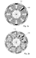
Figures 2a and 2b are schematic diagrams detailing the effect upon resultant magnetic fields of the alignment of the stator and rotor magnets of an embodiment of a magnetic torque oscillation controller according to an aspect of the present invention, and of the offsetting said stator and rotor magnets by 22.5°, respectively; -
Figure 3 is a graphical representation of camshaft torque oscillation reduction achieved employing an embodiment of a magnetic torque oscillation controller according to an aspect of the present invention; and -
Figure 4 is a graphical representation of camshaft torque oscillation enhancement achieved employing an embodiment of a magnetic torque oscillation controller according to an aspect of the present invention. - Referring now to
Figures 1 and 2 , a camshaft-cylinder head arrangement 100 comprises acamshaft 102 and acylinder head 104. - A
tube 106 having a circular cross-section is mounted concentrically with thecamshaft 102. Anopen end 108 of the tube terminated adjacent anouter face 109 of thecylinder head 104. Aninner face 110 of thetube 106 hasrotor magnets 112 located upon it adjacent theopen end 108 of thetube 106. Therotor magnets 112 may comprise permanent magnets. Alternatively, or additionally, therotor magnets 112 may comprise electromagnets. - In the preferred embodiment shown in
Figure 1 there are eightrotor magnets 112 equiangularly spaced about the circumference of theinner face 110. The use of eight magnets in this arrangement is appropriate for a four cylinder four stroke engine. - The
cylinder head 104 comprises anannular block 114 through which thecamshaft 102 passes. Anannular wall 116 projects perpendicularly away from theouter face 109 of thecylinder head 104. Theannular wall 116 is concentric with theblock 114 and has a smaller external radius than the internal radius of thetube 106. - An
exterior surface 118 of thewall 116 hasstator magnets 120 located upon it remote from theouter face 109 of thecylinder head 104. In the preferred embodiment shown inFigure 1 there are eightmagnets 120 equiangularly spaced about the circumference of theexterior surface 118. - During manufacture of an engine the
camshaft 102 andcylinder head 104 are set in an initial position relative to one another. This initial position determines the timing of valve operation. - At this initial position that the resultant magnetic field due to the interaction of the
rotor magnets 112 and thestator magnets 120 at rest is defined. - The
camshaft 102 rotates with respect to thecylinder head 104 causing relative rotation of therotor magnets 112 with respect to thestator magnets 120. This relative rotation causes the magnetic interaction of therotor magnets 112 and thestator magnets 120 to vary. -
Figure 2a shows the effect upon resultant magnetic fields of the alignment of the cylinder head and rotor magnets 104,112 to produce minimum camshaft torque. -
Figure 2b shows the effect upon resultant magnetic fields of offsetting the cylinder head and rotor magnets 104,112 by 22.5° to produce maximum camshaft torque. - The resultant sinusoidal variation in the magnetic forces exerted between the
rotor magnets 112 and thestator magnets 120 either oppose or enhance the torque oscillations experienced by thecamshaft 102. This is dependent upon the arrangement of the magnets relative to each other. - In most cases it is desired to reduce camshaft torque oscillations.
- Referring now to
Figure 3 ,total camshaft torque 302 is due to variable friction and torque oscillations. Amagnetic torque 304 is in antiphase with the totalcamshaft torque oscillations 302. This results in a constantresultant torque 306 acting on thecamshaft 102 of less that 5Nm, typically about 0.5Nm - 2Nm at 90°C oil temperature. - Referring now to
Figure 4 ,total camshaft torque 402 is due to variable friction and torque oscillations. Amagnetic torque 404 of approximately the same magnitude as the camshaft torque oscillations is in phase with thecamshaft torque oscillations 402. This results in a largeresultant torque oscillations 406 acting on thecamshaft 102 having a peak height of approximately 30Nm. - Such an arrangement may be useful where cam actuated torque phasers are used, as the increase in the magnitude the torque oscillation allows rapid phasing.
- It will be appreciated that although described with reference to an engine comprising four cylinders the present invention is equally applicable to an engine having any number of cylinders. The number of magnets provided will vary dependent upon the number of cylinders. The number of magnetic pole pairs required varies with the number of cylinders within the engine. For example an engine comprising six cylinders will require six North-South magnetic pole pairs giving a total of twelve magnets on each of the rotor and stator.
- It will be further appreciate that although described with reference to the application of a radial magnetic torque the present invention is equally applicable to the application of an axial magnetic torque.
Claims (15)
- A magnetic torque oscillation controller for a camshaft (102) comprising first and second magnetic elements (120, 112), the first and second magnetic elements (120, 112) being positionable relative to the other of the first and second magnetic elements (120, 112), wherein the relative positions of the first and second magnetic elements (120, 112)are arranged to either increase or decrease a torque oscillation of the camshaft (102).
- A controller according to claim 1 first magnetic element (120) is located internally of the second magnetic element (112).
- A controller according to either claim 1, or claim 2, wherein first magnetic element (120) comprises a stator.
- A controller according to claim 3 the stator (120) comprises a cylinder head (104).
- A controller according to any preceding claim wherein the first magnetic element (120) comprises a first plurality of magnets.
- A controller according to claim 5 wherein the first plurality of magnets are circumferentially spaced about a surface of an annular disc (104).
- A controller according to claim 6 wherein the first plurality of magnets are equiangularly spaced about the circumference of the disc (104).
- A controller according to claim 5 wherein at least one of the first plurality of magnets is mounted upon a surface (118) of a post or a wall (116).
- A controller according to any one of claims 6 to 8 wherein the surface (118) of the disc (104), the post, or the wall (116), comprises a surface facing away from the camshaft (102).
- A controller according to any preceding claim wherein the second magnetic element (112) comprises a rotor.
- A controller according to claim 10 wherein the rotor comprises the camshaft (102).
- A controller according to any preceding claim wherein the second magnetic element comprises a second plurality of magnets.
- A controller according to claim 12 wherein the second plurality of magnets are circumferentially spaced about a surface of a disc or a channel.
- A controller according to claim 12 wherein at least one of the second plurality of magnets is mounted upon a surface of a post.
- A controller according to any one of claims 5 to 14 wherein either, or both, of the first and second plurality of magnets comprises a multiple of four magnets.
Priority Applications (3)
| Application Number | Priority Date | Filing Date | Title |
|---|---|---|---|
| AT06256170T ATE524640T1 (en) | 2006-12-01 | 2006-12-01 | TORQUE FLUCTUATION CONTROL |
| EP06256170A EP1927733B1 (en) | 2006-12-01 | 2006-12-01 | Torque Oscillation Controller |
| PCT/EP2007/062828 WO2008065086A1 (en) | 2006-12-01 | 2007-11-26 | Torque oscillation controller |
Applications Claiming Priority (1)
| Application Number | Priority Date | Filing Date | Title |
|---|---|---|---|
| EP06256170A EP1927733B1 (en) | 2006-12-01 | 2006-12-01 | Torque Oscillation Controller |
Publications (2)
| Publication Number | Publication Date |
|---|---|
| EP1927733A1 true EP1927733A1 (en) | 2008-06-04 |
| EP1927733B1 EP1927733B1 (en) | 2011-09-14 |
Family
ID=38035012
Family Applications (1)
| Application Number | Title | Priority Date | Filing Date |
|---|---|---|---|
| EP06256170A Not-in-force EP1927733B1 (en) | 2006-12-01 | 2006-12-01 | Torque Oscillation Controller |
Country Status (3)
| Country | Link |
|---|---|
| EP (1) | EP1927733B1 (en) |
| AT (1) | ATE524640T1 (en) |
| WO (1) | WO2008065086A1 (en) |
Cited By (1)
| Publication number | Priority date | Publication date | Assignee | Title |
|---|---|---|---|---|
| EP2180151A1 (en) * | 2008-10-24 | 2010-04-28 | Delphi Technologies, Inc. | Valve gear assembly for an internal combustion engine |
Families Citing this family (2)
| Publication number | Priority date | Publication date | Assignee | Title |
|---|---|---|---|---|
| US9611764B2 (en) | 2014-10-21 | 2017-04-04 | Ford Global Technologies, Llc | Method and system for variable cam timing device |
| US9587525B2 (en) | 2014-10-21 | 2017-03-07 | Ford Global Technologies, Llc | Method and system for variable cam timing device |
Citations (3)
| Publication number | Priority date | Publication date | Assignee | Title |
|---|---|---|---|---|
| GB1256133A (en) * | 1969-06-30 | 1971-12-08 | British Aircraft Corp Ltd | Improvements relating to eddy current damping devices |
| US20050076867A1 (en) * | 2003-10-09 | 2005-04-14 | Denso Corporation | Valve controller |
| DE102004037261A1 (en) * | 2004-07-31 | 2006-03-23 | Ina-Schaeffler Kg | Electric machine at the camshaft of an IC motor, driven by a belt/chain from the camshaft, has a rotor of two rings keyed to the camshaft flanked by stator coils at a holder at the outer ring |
-
2006
- 2006-12-01 EP EP06256170A patent/EP1927733B1/en not_active Not-in-force
- 2006-12-01 AT AT06256170T patent/ATE524640T1/en not_active IP Right Cessation
-
2007
- 2007-11-26 WO PCT/EP2007/062828 patent/WO2008065086A1/en not_active Ceased
Patent Citations (3)
| Publication number | Priority date | Publication date | Assignee | Title |
|---|---|---|---|---|
| GB1256133A (en) * | 1969-06-30 | 1971-12-08 | British Aircraft Corp Ltd | Improvements relating to eddy current damping devices |
| US20050076867A1 (en) * | 2003-10-09 | 2005-04-14 | Denso Corporation | Valve controller |
| DE102004037261A1 (en) * | 2004-07-31 | 2006-03-23 | Ina-Schaeffler Kg | Electric machine at the camshaft of an IC motor, driven by a belt/chain from the camshaft, has a rotor of two rings keyed to the camshaft flanked by stator coils at a holder at the outer ring |
Cited By (1)
| Publication number | Priority date | Publication date | Assignee | Title |
|---|---|---|---|---|
| EP2180151A1 (en) * | 2008-10-24 | 2010-04-28 | Delphi Technologies, Inc. | Valve gear assembly for an internal combustion engine |
Also Published As
| Publication number | Publication date |
|---|---|
| EP1927733B1 (en) | 2011-09-14 |
| ATE524640T1 (en) | 2011-09-15 |
| WO2008065086A1 (en) | 2008-06-05 |
Similar Documents
| Publication | Publication Date | Title |
|---|---|---|
| US5417186A (en) | Dual-acting apparatus for variable valve timing and the like | |
| EP2067961B1 (en) | Coupling device | |
| CN1965150B (en) | Multi-cylinder internal combustion engine valve driving device | |
| US8371257B2 (en) | Engine with dual cam phaser for concentric camshaft | |
| CN102439265B (en) | Phaser assembly for an internal combustion engine | |
| US9810108B2 (en) | Engine variable camshaft timing phaser with planetary gear assembly | |
| US7523728B2 (en) | Phaser for controlling the timing between a camshaft and a timing gear | |
| JP2011163274A (en) | Engine with variable valve device | |
| US20120067317A1 (en) | Anti-cogging apparatus and methods for reducing cogging of rotating shaft | |
| US20150176442A1 (en) | Camshaft-in-camshaft apparatus of variable valve duration system | |
| US10557385B2 (en) | Engine variable camshaft timing phaser with planetary gear assembly | |
| CN1977091B (en) | Engine with variable valve timing | |
| US6932037B2 (en) | Variable CAM timing (VCT) system having modifications to increase CAM torsionals for engines having limited inherent torsionals | |
| US7540266B2 (en) | Rotary-to-linear actuator, linear motion shaft mechanism, variable valve actuation mechanism and variable valve engine | |
| US7100555B2 (en) | Valve timing controller | |
| WO2008065086A1 (en) | Torque oscillation controller | |
| JP2006105062A (en) | Valve operation control device for engine | |
| KR101518951B1 (en) | Variable valve timing camshaft | |
| US10954829B2 (en) | Oldham flexplate for concentric camshafts controlled by variable camshaft timing | |
| RU2709540C2 (en) | Device for reduction of torsion load on cam shaft | |
| US20130152890A1 (en) | Camshaft adjuster arrangement and camshaft adjuster | |
| US20120199085A1 (en) | Camshaft arrangement | |
| US11268412B2 (en) | Camshaft phaser | |
| US11346259B2 (en) | Control apparatus for camshaft phaser | |
| JP2003322034A (en) | Internal combustion engine |
Legal Events
| Date | Code | Title | Description |
|---|---|---|---|
| PUAI | Public reference made under article 153(3) epc to a published international application that has entered the european phase |
Free format text: ORIGINAL CODE: 0009012 |
|
| 17P | Request for examination filed |
Effective date: 20070607 |
|
| AK | Designated contracting states |
Kind code of ref document: A1 Designated state(s): AT BE BG CH CY CZ DE DK EE ES FI FR GB GR HU IE IS IT LI LT LU LV MC NL PL PT RO SE SI SK TR |
|
| AX | Request for extension of the european patent |
Extension state: AL BA HR MK RS |
|
| AKX | Designation fees paid |
Designated state(s): AT BE BG CH CY CZ DE DK EE ES FI FR GB GR HU IE IS IT LI LT LU LV MC NL PL PT RO SE SI SK TR |
|
| 17Q | First examination report despatched |
Effective date: 20090728 |
|
| GRAP | Despatch of communication of intention to grant a patent |
Free format text: ORIGINAL CODE: EPIDOSNIGR1 |
|
| GRAS | Grant fee paid |
Free format text: ORIGINAL CODE: EPIDOSNIGR3 |
|
| GRAA | (expected) grant |
Free format text: ORIGINAL CODE: 0009210 |
|
| RIN1 | Information on inventor provided before grant (corrected) |
Inventor name: FARAH, PHILIPPE-SIAD |
|
| AK | Designated contracting states |
Kind code of ref document: B1 Designated state(s): AT BE BG CH CY CZ DE DK EE ES FI FR GB GR HU IE IS IT LI LT LU LV MC NL PL PT RO SE SI SK TR |
|
| REG | Reference to a national code |
Ref country code: GB Ref legal event code: FG4D |
|
| REG | Reference to a national code |
Ref country code: CH Ref legal event code: EP |
|
| REG | Reference to a national code |
Ref country code: IE Ref legal event code: FG4D |
|
| REG | Reference to a national code |
Ref country code: DE Ref legal event code: R096 Ref document number: 602006024355 Country of ref document: DE Effective date: 20111110 |
|
| REG | Reference to a national code |
Ref country code: NL Ref legal event code: VDEP Effective date: 20110914 |
|
| PG25 | Lapsed in a contracting state [announced via postgrant information from national office to epo] |
Ref country code: SE Free format text: LAPSE BECAUSE OF FAILURE TO SUBMIT A TRANSLATION OF THE DESCRIPTION OR TO PAY THE FEE WITHIN THE PRESCRIBED TIME-LIMIT Effective date: 20110914 Ref country code: FI Free format text: LAPSE BECAUSE OF FAILURE TO SUBMIT A TRANSLATION OF THE DESCRIPTION OR TO PAY THE FEE WITHIN THE PRESCRIBED TIME-LIMIT Effective date: 20110914 Ref country code: LT Free format text: LAPSE BECAUSE OF FAILURE TO SUBMIT A TRANSLATION OF THE DESCRIPTION OR TO PAY THE FEE WITHIN THE PRESCRIBED TIME-LIMIT Effective date: 20110914 |
|
| LTIE | Lt: invalidation of european patent or patent extension |
Effective date: 20110914 |
|
| PG25 | Lapsed in a contracting state [announced via postgrant information from national office to epo] |
Ref country code: SI Free format text: LAPSE BECAUSE OF FAILURE TO SUBMIT A TRANSLATION OF THE DESCRIPTION OR TO PAY THE FEE WITHIN THE PRESCRIBED TIME-LIMIT Effective date: 20110914 Ref country code: LV Free format text: LAPSE BECAUSE OF FAILURE TO SUBMIT A TRANSLATION OF THE DESCRIPTION OR TO PAY THE FEE WITHIN THE PRESCRIBED TIME-LIMIT Effective date: 20110914 Ref country code: AT Free format text: LAPSE BECAUSE OF FAILURE TO SUBMIT A TRANSLATION OF THE DESCRIPTION OR TO PAY THE FEE WITHIN THE PRESCRIBED TIME-LIMIT Effective date: 20110914 Ref country code: GR Free format text: LAPSE BECAUSE OF FAILURE TO SUBMIT A TRANSLATION OF THE DESCRIPTION OR TO PAY THE FEE WITHIN THE PRESCRIBED TIME-LIMIT Effective date: 20111215 Ref country code: CY Free format text: LAPSE BECAUSE OF FAILURE TO SUBMIT A TRANSLATION OF THE DESCRIPTION OR TO PAY THE FEE WITHIN THE PRESCRIBED TIME-LIMIT Effective date: 20110914 |
|
| REG | Reference to a national code |
Ref country code: AT Ref legal event code: MK05 Ref document number: 524640 Country of ref document: AT Kind code of ref document: T Effective date: 20110914 |
|
| PG25 | Lapsed in a contracting state [announced via postgrant information from national office to epo] |
Ref country code: BE Free format text: LAPSE BECAUSE OF FAILURE TO SUBMIT A TRANSLATION OF THE DESCRIPTION OR TO PAY THE FEE WITHIN THE PRESCRIBED TIME-LIMIT Effective date: 20110914 |
|
| PG25 | Lapsed in a contracting state [announced via postgrant information from national office to epo] |
Ref country code: IS Free format text: LAPSE BECAUSE OF FAILURE TO SUBMIT A TRANSLATION OF THE DESCRIPTION OR TO PAY THE FEE WITHIN THE PRESCRIBED TIME-LIMIT Effective date: 20120114 Ref country code: CZ Free format text: LAPSE BECAUSE OF FAILURE TO SUBMIT A TRANSLATION OF THE DESCRIPTION OR TO PAY THE FEE WITHIN THE PRESCRIBED TIME-LIMIT Effective date: 20110914 Ref country code: SK Free format text: LAPSE BECAUSE OF FAILURE TO SUBMIT A TRANSLATION OF THE DESCRIPTION OR TO PAY THE FEE WITHIN THE PRESCRIBED TIME-LIMIT Effective date: 20110914 |
|
| PG25 | Lapsed in a contracting state [announced via postgrant information from national office to epo] |
Ref country code: IT Free format text: LAPSE BECAUSE OF FAILURE TO SUBMIT A TRANSLATION OF THE DESCRIPTION OR TO PAY THE FEE WITHIN THE PRESCRIBED TIME-LIMIT Effective date: 20110914 Ref country code: PT Free format text: LAPSE BECAUSE OF FAILURE TO SUBMIT A TRANSLATION OF THE DESCRIPTION OR TO PAY THE FEE WITHIN THE PRESCRIBED TIME-LIMIT Effective date: 20120116 Ref country code: PL Free format text: LAPSE BECAUSE OF FAILURE TO SUBMIT A TRANSLATION OF THE DESCRIPTION OR TO PAY THE FEE WITHIN THE PRESCRIBED TIME-LIMIT Effective date: 20110914 Ref country code: EE Free format text: LAPSE BECAUSE OF FAILURE TO SUBMIT A TRANSLATION OF THE DESCRIPTION OR TO PAY THE FEE WITHIN THE PRESCRIBED TIME-LIMIT Effective date: 20110914 Ref country code: NL Free format text: LAPSE BECAUSE OF FAILURE TO SUBMIT A TRANSLATION OF THE DESCRIPTION OR TO PAY THE FEE WITHIN THE PRESCRIBED TIME-LIMIT Effective date: 20110914 Ref country code: RO Free format text: LAPSE BECAUSE OF FAILURE TO SUBMIT A TRANSLATION OF THE DESCRIPTION OR TO PAY THE FEE WITHIN THE PRESCRIBED TIME-LIMIT Effective date: 20110914 |
|
| PLBE | No opposition filed within time limit |
Free format text: ORIGINAL CODE: 0009261 |
|
| STAA | Information on the status of an ep patent application or granted ep patent |
Free format text: STATUS: NO OPPOSITION FILED WITHIN TIME LIMIT |
|
| PG25 | Lapsed in a contracting state [announced via postgrant information from national office to epo] |
Ref country code: MC Free format text: LAPSE BECAUSE OF NON-PAYMENT OF DUE FEES Effective date: 20111231 Ref country code: DK Free format text: LAPSE BECAUSE OF FAILURE TO SUBMIT A TRANSLATION OF THE DESCRIPTION OR TO PAY THE FEE WITHIN THE PRESCRIBED TIME-LIMIT Effective date: 20110914 |
|
| REG | Reference to a national code |
Ref country code: CH Ref legal event code: PL |
|
| 26N | No opposition filed |
Effective date: 20120615 |
|
| GBPC | Gb: european patent ceased through non-payment of renewal fee |
Effective date: 20111214 |
|
| REG | Reference to a national code |
Ref country code: IE Ref legal event code: MM4A |
|
| REG | Reference to a national code |
Ref country code: DE Ref legal event code: R097 Ref document number: 602006024355 Country of ref document: DE Effective date: 20120615 |
|
| PG25 | Lapsed in a contracting state [announced via postgrant information from national office to epo] |
Ref country code: CH Free format text: LAPSE BECAUSE OF NON-PAYMENT OF DUE FEES Effective date: 20111231 Ref country code: LI Free format text: LAPSE BECAUSE OF NON-PAYMENT OF DUE FEES Effective date: 20111231 Ref country code: IE Free format text: LAPSE BECAUSE OF NON-PAYMENT OF DUE FEES Effective date: 20111201 Ref country code: GB Free format text: LAPSE BECAUSE OF NON-PAYMENT OF DUE FEES Effective date: 20111214 |
|
| PG25 | Lapsed in a contracting state [announced via postgrant information from national office to epo] |
Ref country code: ES Free format text: LAPSE BECAUSE OF FAILURE TO SUBMIT A TRANSLATION OF THE DESCRIPTION OR TO PAY THE FEE WITHIN THE PRESCRIBED TIME-LIMIT Effective date: 20111225 |
|
| PG25 | Lapsed in a contracting state [announced via postgrant information from national office to epo] |
Ref country code: LU Free format text: LAPSE BECAUSE OF NON-PAYMENT OF DUE FEES Effective date: 20111201 |
|
| PG25 | Lapsed in a contracting state [announced via postgrant information from national office to epo] |
Ref country code: BG Free format text: LAPSE BECAUSE OF FAILURE TO SUBMIT A TRANSLATION OF THE DESCRIPTION OR TO PAY THE FEE WITHIN THE PRESCRIBED TIME-LIMIT Effective date: 20111214 |
|
| PG25 | Lapsed in a contracting state [announced via postgrant information from national office to epo] |
Ref country code: TR Free format text: LAPSE BECAUSE OF FAILURE TO SUBMIT A TRANSLATION OF THE DESCRIPTION OR TO PAY THE FEE WITHIN THE PRESCRIBED TIME-LIMIT Effective date: 20110914 |
|
| PG25 | Lapsed in a contracting state [announced via postgrant information from national office to epo] |
Ref country code: HU Free format text: LAPSE BECAUSE OF FAILURE TO SUBMIT A TRANSLATION OF THE DESCRIPTION OR TO PAY THE FEE WITHIN THE PRESCRIBED TIME-LIMIT Effective date: 20110914 |
|
| PGFP | Annual fee paid to national office [announced via postgrant information from national office to epo] |
Ref country code: FR Payment date: 20131217 Year of fee payment: 8 |
|
| REG | Reference to a national code |
Ref country code: FR Ref legal event code: ST Effective date: 20150831 |
|
| PG25 | Lapsed in a contracting state [announced via postgrant information from national office to epo] |
Ref country code: FR Free format text: LAPSE BECAUSE OF NON-PAYMENT OF DUE FEES Effective date: 20141231 |
|
| PGFP | Annual fee paid to national office [announced via postgrant information from national office to epo] |
Ref country code: DE Payment date: 20161229 Year of fee payment: 11 |
|
| REG | Reference to a national code |
Ref country code: DE Ref legal event code: R119 Ref document number: 602006024355 Country of ref document: DE |
|
| PG25 | Lapsed in a contracting state [announced via postgrant information from national office to epo] |
Ref country code: DE Free format text: LAPSE BECAUSE OF NON-PAYMENT OF DUE FEES Effective date: 20180703 |