EP1927564A1 - Sheet flipping device - Google Patents
Sheet flipping device Download PDFInfo
- Publication number
- EP1927564A1 EP1927564A1 EP07121094A EP07121094A EP1927564A1 EP 1927564 A1 EP1927564 A1 EP 1927564A1 EP 07121094 A EP07121094 A EP 07121094A EP 07121094 A EP07121094 A EP 07121094A EP 1927564 A1 EP1927564 A1 EP 1927564A1
- Authority
- EP
- European Patent Office
- Prior art keywords
- flipping
- sheet
- volume
- receiving member
- electrodes
- Prior art date
- Legal status (The legal status is an assumption and is not a legal conclusion. Google has not performed a legal analysis and makes no representation as to the accuracy of the status listed.)
- Granted
Links
Images




Classifications
-
- B—PERFORMING OPERATIONS; TRANSPORTING
- B65—CONVEYING; PACKING; STORING; HANDLING THIN OR FILAMENTARY MATERIAL
- B65H—HANDLING THIN OR FILAMENTARY MATERIAL, e.g. SHEETS, WEBS, CABLES
- B65H29/00—Delivering or advancing articles from machines; Advancing articles to or into piles
- B65H29/38—Delivering or advancing articles from machines; Advancing articles to or into piles by movable piling or advancing arms, frames, plates, or like members with which the articles are maintained in face contact
- B65H29/40—Members rotated about an axis perpendicular to direction of article movement, e.g. star-wheels formed by S-shaped members
Definitions
- the invention relates to a sheet flipping device, comprising a receiving member for receiving a sheet, a flipping volume being substantially the volume which in operation is defined by the flipping movement of the sheet, a flipping element for flipping the sheet around an axis of rotation within the flipping volume onto the receiving member.
- the invention also relates to a sheet stacking device and a image reproduction apparatus.
- a device of this kind is described in FR 2 760 733 .
- the device uses a flipping wheel to stack sheets on a receiving member in a flipped orientation.
- the flipping wheel comprises slits at its circumference to accommodate portions of a sheet.
- An abutment is provided to release the sheets from the slit onto the receiving member.
- certain types of sheets in particular floppy sheets with low stiffness in the direction of rotation, do not roll out correctly onto the receiving member, resulting in a less orderly stack or may even result in device blocks, such as paper jams.
- a sheet flipping device which further comprises a discharge element arranged adjacent to said flipping volume, having a base extending in a direction substantially perpendicular to the direction of the axis of rotation said discharge element having multiple electrodes having an end portion extending in a direction towards the flipping volume.
- the multiple electrodes each have a sharp ending pointing towards the flipping volume. It has been observed that sharp endings which point towards the flipping volume further increase the reliability of the sheet flipping device by further decreasing the risk of a erroneous roll out of a flipping sheet.
- the multiple electrodes each have a top angle of less than 30°. It has been found that a top angle of less than 30° is sharp enough for situations in devices as presently presented, i.e. used materials and occurring distances to overcome roll out problems sufficiently. It is preferred to implement top angles of 15° or less.
- the discharge element is electrically connected to earth potential. It has been observed that a connection to earth of the discharge element declines the risk of collapsing sheets during roll out after or during flipping.
- said multiple electrodes comprise pin-electrodes.
- Pin-electrodes are usually relatively stiff with respect to flipping sheets. Discharge elements that are provided with pin-electrodes adjacent to the flipping volume have a positive influence on the reliability of the flipping device.
- the construction of pin-electrodes can be cost-efficient as they may be constructed from a single workpiece by milling, e.g. stainless steel or any other electrically conductive material or material with an electrically conductive surface.
- each of said multiple electrodes comprise a fibre organ provided with a conductive outer surface.
- the fibre organ provides a flexible base for the electrically conductive outer surface.
- the fibre does not need to be electrically conductive itself.
- the mechanical flexibility of this type of electrodes provides additional flexibility in the positioning of the discharge element with respect to handling different sheet sizes. Although it is preferred to arrange the discharge elements such that the end-portions are positioned just outside of the flipping volume, this type of mechanical flexible electrodes do not disturb the formation of a straight stack when the end-portions are positioned slightly inside the flipping volume. If a sheet touches a small portion of such electrode it will flex automatically and continue its flipping movement almost undisturbed.
- the electrically conductive outer surface may comprise carbon or any other suitable conductive material.
- the discharge element is arranged moveably, such that the lateral position with respect to the sheet is adaptable.
- the discharge element in particular of the end-portions of the electrodes thereon, a variety of sheet sizes may be handled.
- the end-portions of the electrodes just outside of the flipping volume in order not to disturb the flipping sheets' movement and to be close enough to function efficiently.
- the adaptation of lateral position may be manual or automated in accordance with a measurement or other electrical signal, for example a signal from a printer controller of a printer coupled to such a flipping device.
- the sheet flipping device further comprises a module for generating an airflow in the direction of the flipping sheets' movement such that the flipping of the sheet is assisted during at least a part of the flipping movement of the sheet.
- a module for generating an airflow may for example comprise a ventilator that blows in the direction of the sheet's flipping movement, or a suction device that sucks the sheet during at least a part of the flipping movement in the direction of flipping.
- a combination of sucking and blowing or other modules for generating airflow are also implementable.
- Fig. 1 is a schematic perspective view showing a sheet stacking device comprising a flipping device.
- This sheet stacking device 200 comprises a receiving member 201 to receive sheets to form a stack of sheets 205.
- the sheet stacking device further comprises a rotatable flipping element, such as a flipping wheel 202.
- This flipping wheel has two slits 210 arranged around its circumference. These slits 210 are devised such that sheets which are fed towards the flipping wheel 202 in input direction I and are at least partly received by the slits 210.
- the flipping wheel 202 is rotatably driven by means of drive motor 203 and coupled drive shaft 204. By rotating the flipping wheel 202 in rotational direction R, the sheets are flipped over and arranged on top of the receiving member 201 or previously formed stack 205.
- the sheet stacking device has a relative high degree of erroneous formed stacks.
- Fig. 2 shows a problem during operation of the sheet stacking device resulting in an erroneous formed stack.
- the leading edge of the sheet has been received by the slit 210 and driven to be flipped.
- the sheet has a problem rolling out onto the top of the stack 205 formed on the receiving member 201.
- floppy sheets with relative low stiffness in the direction of rotation tend to collapse onto itself during flipping, preventing a smooth roll out onto the top of the stack 205. This results in a less well-aligned stack of sheets and may even result in the blocking of the device.
- Fig. 3A is a schematic perspective view of an embodiment of a sheet stacking device comprising a flipping device according to the invention.
- the stacking device 100 comprises a rotatable sheet flipping wheel 102 as a sheet flipping element.
- This sheet flipping wheel 102 has two slits 110 at its circumference to accommodate at least a portion of an incoming sheet.
- the sheet flipping wheel 102 is connected to a drive motor 103 via a drive shaft 104.
- a sheet receiving member 101 is provided to accommodate a sheet of a stack of sheets 105.
- the height of the sheet receiving member 101 relative to the flipping wheel 102 is adaptable to enable an enlarged sheet accommodation capacity while sheets are controllably released onto the top of the receiving member 101 or an already formed stack of sheets 105.
- the sheet receiving member 101 may have a fixed height relative to the flipping wheel 102.
- the sheet flipping device is further provided with two discharge elements 150, 151 arranged adjacent to the flipping volume.
- This flipping volume is substantially the volume through which the sheet 111 is actually moved during its flipping movement in operation from its initial position to its flipped position on top of the receiving member 101 or the previously formed stack 105.
- the discharge elements 150, 151 have bases 112, 113 extending in a direction substantially perpendicular to the direction of the axis of rotation of the flipping wheel 102.
- the discharge elements 150, 151 have multiple electrodes 120 arranged on the bases 112, 113 having an end portion extending in a direction towards the flipping volume.
- the discharge elements 150, 151 are mounted on an apparatus frame (not shown) via frame mounts 115, 116.
- an incoming sheet is fed towards the sheet flipping wheel 102 in direction A from a supply or any sheet processing unit (not shown).
- the leading edge portion of sheet 111 has been accommodated in slit 110, rotated in direction of rotation R by driving the driving motor 103 for approximately a half revolution.
- the leading edge portion of the sheet 111 is released from the slit 110 by means of an abutment (not shown) which is arranged between two segments of the flipping wheel 102.
- the sheet 111 will be released and accommodated on top of the previously formed stack 105 in a flipped orientation with respect to its original orientation.
- the electrodes 120 of the discharge elements 150, 151 have a sharp ending, pointing towards the flipping volume to enable a discharge during the flipping of a sheet 111.
- the electrodes 120 are electrically conductive. Electrically conductive electrodes 120 are electrically connected to the bases 112, 113.
- the bases 112, 113 are connected to earth potential.
- the discharge element 150, 151 is constructed as an integral element formed from a single workpiece, e.g. stainless steel or any other electrical conductive material but may alternatively also be constructed as a modular assembly wherein the electrodes 120 are individually mounted on the base 112, 113.
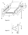
- Fig. 3B is a schematic top view close-up of an electrode for use in the sheet stacking device of Fig. 3A .
- the electrode 120 and base 113 are formed from a single piece of stainless steel by milling.
- the top angle ⁇ must be highly curved, such that it is sharp enough to enable a discharge, in this case smaller than 30°, but preferably less than 15°.
- Fig. 4A is a schematic perspective view of an embodiment of a sheet stacking device comprising a flipping device according to the invention. It generally equals the device as presented in Fig. 3 , but in particular the discharge elements are implemented with fibre electrodes 130.
- the fibre electrodes 130 are mounted on the bases 112, 113 of the discharge elements 150, 160.
- Each fibre electrode 130 comprises a flexible fibre organ provided with a conductive outer surface.
- Fibre electrodes 130 may be mounted on the bases 112, 113 individually or in groups.
- Fig. 4B is a schematic top view close-up of an electrode for use in the sheet stacking device of Fig. 4A .
- the fibre electrode 130 is mounted on base 113 by means of a fibre organ 131, which is anchored in the base 113.
- the flexible fibre organ 131 is provided with an electrically conductive surface layer 135.
- the electrically conductive outer surface 135 is connected to earth potential.
- the fibre electrode 130 is taller than illustrated in Fig. 4B , similar to a flexible needle or hair-like object.
- the fibre electrode 130 is mounted individually on the base 113, by may alternatively be mounted in groups of clusters of fibre electrodes 130. In that case the connection with earth potential may also be collectively.
- Fig. 5 is a schematic view showing a flipping sheet in the flipping volume.
- a sheet 11 that is flipped using a sheet flipping device according to the invention (not shown) is moved through a flipping volume 10.
- This flipping volume 10 is substantially the volume through which the sheet 11 is actually moved during its flipping movement in operation from its initial position 11 to its flipped position 11'.
- the flipping element (not shown) flips the sheet 11 around axis of rotation, indicated as the dashed bold line in rotational direction R.
- the flipping volume 10 is span by the accumulated positions of the sheet 11 during its flipping movement towards position 11'.
- the flipping volume 10 is indicated by means of the dashed lined volume.
- the discharge elements are arranged adjacent to the flipping volume.
- the discharge elements are generally arranged adjacent to the flipping volume of the sheet size with the largest width. If the end portions of the electrodes are sharp enough, the electrodes will still enable a discharge to smaller sheet sizes.
- the discharge elements may be arranged in a moveable fashion, such that the lateral position of the discharge elements may vary in dependence with the actual sheet size.
- Fig. 6 is a schematic side view of multiple embodiments of a flipping device according to the invention.
- Fig. 6A illustrates the embodiment wherein the discharge element 150 is arranged along a substantial length of the receiving member 101. This embodiment is further illustrated in Fig. 3 .
- Fig. 6B illustrates the embodiment wherein the discharge element 150 is arranged on a relatively short stretch on a relatively high position with respect to the flipping volume 10.
- Fig. 6C illustrates the embodiment wherein the discharge element 150 is arranged along a substantial length of the receiving member 101 at a downward slope with respect to the receiving member 101. This embodiment is further illustrated in Fig. 4 .
- Fig. 6C illustrates the embodiment wherein the discharge element 150 is arranged along a substantial length of the receiving member 101 at an upward slope with respect to the receiving member 101.
- Fig. 6 A-D may be implemented with any of the previously described electrodes. It will be clear for the person skilled in the art that any combination or iteration of the presented embodiments may produce a working embodiment.
- End-portions of electrodes may extend slightly into the flipping volume 10 thereby slightly toughing the flipping sheets, but preferably the end-portions are arranged just outside adjacent to the flipping volume.
Landscapes
- Engineering & Computer Science (AREA)
- Mechanical Engineering (AREA)
- Pile Receivers (AREA)
Abstract
Description
- The invention relates to a sheet flipping device, comprising a receiving member for receiving a sheet, a flipping volume being substantially the volume which in operation is defined by the flipping movement of the sheet, a flipping element for flipping the sheet around an axis of rotation within the flipping volume onto the receiving member. The invention also relates to a sheet stacking device and a image reproduction apparatus.
- A device of this kind is described in
FR 2 760 733
However, it is a disadvantage of this known device that certain types of sheets, in particular floppy sheets with low stiffness in the direction of rotation, do not roll out correctly onto the receiving member, resulting in a less orderly stack or may even result in device blocks, such as paper jams. - It is an object of the invention to improve the roll out of sheets onto the receiving member for flipping devices. To this end a sheet flipping device is provided which further comprises a discharge element arranged adjacent to said flipping volume, having a base extending in a direction substantially perpendicular to the direction of the axis of rotation said discharge element having multiple electrodes having an end portion extending in a direction towards the flipping volume.
It is observed that the implementation of such a discharge element, which is arranged adjacent to the flipping volume, surprisingly increases the reliability of the flipping device as a result of better roll out of flipped sheets. Even without any physical contact between the discharge elements and the flipping sheets, the roll out of sheets, even of very floppy sheets, improves significantly. - In another embodiment of the device according to the invention the multiple electrodes each have a sharp ending pointing towards the flipping volume. It has been observed that sharp endings which point towards the flipping volume further increase the reliability of the sheet flipping device by further decreasing the risk of a erroneous roll out of a flipping sheet.
- In a further embodiment of the device according to the invention, the multiple electrodes each have a top angle of less than 30°. It has been found that a top angle of less than 30° is sharp enough for situations in devices as presently presented, i.e. used materials and occurring distances to overcome roll out problems sufficiently. It is preferred to implement top angles of 15° or less.
- In another embodiment of the device according to the invention, the discharge element is electrically connected to earth potential. It has been observed that a connection to earth of the discharge element declines the risk of collapsing sheets during roll out after or during flipping.
- In another embodiment of the device according to the invention, said multiple electrodes comprise pin-electrodes. Pin-electrodes are usually relatively stiff with respect to flipping sheets. Discharge elements that are provided with pin-electrodes adjacent to the flipping volume have a positive influence on the reliability of the flipping device. The construction of pin-electrodes can be cost-efficient as they may be constructed from a single workpiece by milling, e.g. stainless steel or any other electrically conductive material or material with an electrically conductive surface.
- In an embodiment of the device according to the invention, each of said multiple electrodes comprise a fibre organ provided with a conductive outer surface. The fibre organ provides a flexible base for the electrically conductive outer surface. The fibre does not need to be electrically conductive itself. The mechanical flexibility of this type of electrodes provides additional flexibility in the positioning of the discharge element with respect to handling different sheet sizes. Although it is preferred to arrange the discharge elements such that the end-portions are positioned just outside of the flipping volume, this type of mechanical flexible electrodes do not disturb the formation of a straight stack when the end-portions are positioned slightly inside the flipping volume. If a sheet touches a small portion of such electrode it will flex automatically and continue its flipping movement almost undisturbed.
The electrically conductive outer surface may comprise carbon or any other suitable conductive material. - In another embodiment of the device according to the invention, the discharge element is arranged moveably, such that the lateral position with respect to the sheet is adaptable. By enabling a laterally adaptable positioning of the discharge element, in particular of the end-portions of the electrodes thereon, a variety of sheet sizes may be handled. As it is preferred to arrange the end-portions of the electrodes just outside of the flipping volume in order not to disturb the flipping sheets' movement and to be close enough to function efficiently.
The adaptation of lateral position may be manual or automated in accordance with a measurement or other electrical signal, for example a signal from a printer controller of a printer coupled to such a flipping device. - In another embodiment of the device according to the invention, the sheet flipping device further comprises a module for generating an airflow in the direction of the flipping sheets' movement such that the flipping of the sheet is assisted during at least a part of the flipping movement of the sheet. A module for generating an airflow may for example comprise a ventilator that blows in the direction of the sheet's flipping movement, or a suction device that sucks the sheet during at least a part of the flipping movement in the direction of flipping. A combination of sucking and blowing or other modules for generating airflow are also implementable.
- The invention will now be explained with reference to the following examples and figures.
-
Fig. 1 is a schematic perspective view showing a sheet stacking device comprising a flipping device; -
Fig. 2 is a schematic perspective view showing a sheet stacking device comprising a flipping device in operation; -
Fig. 3A and4A are schematic perspective views of embodiments of a sheet stacking device comprising a flipping device according to the invention; -
Fig. 3B and4B are schematic top view close-ups of electrodes for use in the embodiments of a sheet stacking device comprising a flipping device according to the invention; -
Fig. 5 is a schematic view showing a flipping sheet in the flipping volume; -
Fig. 6 is a schematic side view of multiple embodiments of a flipping device according to the invention; -
Fig. 1 is a schematic perspective view showing a sheet stacking device comprising a flipping device. Thissheet stacking device 200 comprises a receivingmember 201 to receive sheets to form a stack ofsheets 205. The sheet stacking device further comprises a rotatable flipping element, such as a flippingwheel 202. This flipping wheel has twoslits 210 arranged around its circumference. Theseslits 210 are devised such that sheets which are fed towards the flippingwheel 202 in input direction I and are at least partly received by theslits 210. The flippingwheel 202 is rotatably driven by means ofdrive motor 203 and coupleddrive shaft 204. By rotating the flippingwheel 202 in rotational direction R, the sheets are flipped over and arranged on top of the receivingmember 201 or previously formedstack 205. The sheet stacking device has a relative high degree of erroneous formed stacks. -
Fig. 2 shows a problem during operation of the sheet stacking device resulting in an erroneous formed stack. The leading edge of the sheet has been received by theslit 210 and driven to be flipped. During the final part of the flipping of the sheet, the sheet has a problem rolling out onto the top of thestack 205 formed on thereceiving member 201. In particular floppy sheets with relative low stiffness in the direction of rotation tend to collapse onto itself during flipping, preventing a smooth roll out onto the top of thestack 205. This results in a less well-aligned stack of sheets and may even result in the blocking of the device. -
Fig. 3A is a schematic perspective view of an embodiment of a sheet stacking device comprising a flipping device according to the invention. Thestacking device 100 comprises a rotatablesheet flipping wheel 102 as a sheet flipping element. Thissheet flipping wheel 102 has twoslits 110 at its circumference to accommodate at least a portion of an incoming sheet. The sheet flippingwheel 102 is connected to adrive motor 103 via adrive shaft 104. Asheet receiving member 101 is provided to accommodate a sheet of a stack ofsheets 105. The height of thesheet receiving member 101 relative to theflipping wheel 102 is adaptable to enable an enlarged sheet accommodation capacity while sheets are controllably released onto the top of the receivingmember 101 or an already formed stack ofsheets 105. Alternatively thesheet receiving member 101 may have a fixed height relative to theflipping wheel 102.
The sheet flipping device is further provided with twodischarge elements sheet 111 is actually moved during its flipping movement in operation from its initial position to its flipped position on top of the receivingmember 101 or the previously formedstack 105. Thedischarge elements bases wheel 102. Thedischarge elements multiple electrodes 120 arranged on thebases discharge elements
In operation an incoming sheet is fed towards thesheet flipping wheel 102 in direction A from a supply or any sheet processing unit (not shown). In the illustrated situation, the leading edge portion ofsheet 111 has been accommodated inslit 110, rotated in direction of rotation R by driving the drivingmotor 103 for approximately a half revolution. At this point the leading edge portion of thesheet 111 is released from theslit 110 by means of an abutment (not shown) which is arranged between two segments of the flippingwheel 102. By rotating the flippingwheel 102 further, thesheet 111 will be released and accommodated on top of the previously formedstack 105 in a flipped orientation with respect to its original orientation.
Theelectrodes 120 of thedischarge elements sheet 111. Theelectrodes 120 are electrically conductive. Electricallyconductive electrodes 120 are electrically connected to thebases bases discharge element electrodes 120 are individually mounted on thebase -
Fig. 3B is a schematic top view close-up of an electrode for use in the sheet stacking device ofFig. 3A . Theelectrode 120 andbase 113 are formed from a single piece of stainless steel by milling. The top angle α must be highly curved, such that it is sharp enough to enable a discharge, in this case smaller than 30°, but preferably less than 15°. -
Fig. 4A is a schematic perspective view of an embodiment of a sheet stacking device comprising a flipping device according to the invention. It generally equals the device as presented inFig. 3 , but in particular the discharge elements are implemented withfibre electrodes 130. Thefibre electrodes 130 are mounted on thebases discharge elements 150, 160. Eachfibre electrode 130 comprises a flexible fibre organ provided with a conductive outer surface.Fibre electrodes 130 may be mounted on thebases -
Fig. 4B is a schematic top view close-up of an electrode for use in the sheet stacking device ofFig. 4A . Thefibre electrode 130 is mounted onbase 113 by means of afibre organ 131, which is anchored in thebase 113. Theflexible fibre organ 131 is provided with an electricallyconductive surface layer 135. The electrically conductiveouter surface 135 is connected to earth potential. In practise thefibre electrode 130 is taller than illustrated inFig. 4B , similar to a flexible needle or hair-like object. Thefibre electrode 130 is mounted individually on thebase 113, by may alternatively be mounted in groups of clusters offibre electrodes 130. In that case the connection with earth potential may also be collectively. -
Fig. 5 is a schematic view showing a flipping sheet in the flipping volume. Asheet 11 that is flipped using a sheet flipping device according to the invention (not shown) is moved through a flippingvolume 10. This flippingvolume 10 is substantially the volume through which thesheet 11 is actually moved during its flipping movement in operation from itsinitial position 11 to its flipped position 11'. The flipping element (not shown) flips thesheet 11 around axis of rotation, indicated as the dashed bold line in rotational direction R. The flippingvolume 10 is span by the accumulated positions of thesheet 11 during its flipping movement towards position 11'. The flippingvolume 10 is indicated by means of the dashed lined volume.
In the flipping device according to the invention, the discharge elements are arranged adjacent to the flipping volume. In practise a variety of sheet sizes may be processed and stacked. Therefore the discharge elements are generally arranged adjacent to the flipping volume of the sheet size with the largest width. If the end portions of the electrodes are sharp enough, the electrodes will still enable a discharge to smaller sheet sizes.
Alternatively, the discharge elements may be arranged in a moveable fashion, such that the lateral position of the discharge elements may vary in dependence with the actual sheet size. -
Fig. 6 is a schematic side view of multiple embodiments of a flipping device according to the invention.Fig. 6A illustrates the embodiment wherein thedischarge element 150 is arranged along a substantial length of the receivingmember 101. This embodiment is further illustrated inFig. 3 .
Fig. 6B illustrates the embodiment wherein thedischarge element 150 is arranged on a relatively short stretch on a relatively high position with respect to the flippingvolume 10.
Fig. 6C illustrates the embodiment wherein thedischarge element 150 is arranged along a substantial length of the receivingmember 101 at a downward slope with respect to the receivingmember 101. This embodiment is further illustrated inFig. 4 .
Fig. 6C illustrates the embodiment wherein thedischarge element 150 is arranged along a substantial length of the receivingmember 101 at an upward slope with respect to the receivingmember 101. - The illustrated embodiments of
Fig. 6 A-D may be implemented with any of the previously described electrodes. It will be clear for the person skilled in the art that any combination or iteration of the presented embodiments may produce a working embodiment. - End-portions of electrodes may extend slightly into the flipping
volume 10 thereby slightly toughing the flipping sheets, but preferably the end-portions are arranged just outside adjacent to the flipping volume.
Claims (10)
- Sheet flipping device, comprising a receiving member for receiving a sheet, a flipping volume being substantially the volume which in operation is defined by the flipping movement of the sheet, a flipping element for flipping the sheet around an axis of rotation within the flipping volume onto the receiving member, characterised in that it further comprises a discharge element arranged adjacent to said flipping volume, the discharge element having a base extending in a direction substantially perpendicular to the direction of the axis of rotation and having multiple electrodes with an end portion extending in a direction towards the flipping volume.
- Sheet flipping device according to claim 1, wherein the multiple electrodes each have a sharp ending pointing towards the flipping volume.
- Sheet flipping device according to claim 2, wherein the multiple electrodes each have a top angle of less than 30°.
- Sheet flipping device according to any one of preceding claims, wherein the discharge element is electrically connected to earth potential.
- Sheet flipping device according to any one of preceding claims, wherein said multiple electrodes comprise pin-electrodes.
- Sheet flipping device according to any one of preceding claims, wherein each of said multiple electrodes comprise a fibre organ provided with a conductive outer surface.
- Sheet flipping device according to claim 6, wherein the conductive outer surface comprises carbon.
- Sheet flipping device according to any one of preceding claims, wherein the discharge element is arranged moveably, such that the lateral position with respect to the sheet is adaptable.
- Sheet stacking device, comprising a sheet flipping device according to any one of claims 1 - 8.
- Image reproduction apparatus comprising a sheet stacking device according to claim 9.
Priority Applications (1)
| Application Number | Priority Date | Filing Date | Title |
|---|---|---|---|
| EP07121094.2A EP1927564B1 (en) | 2006-12-01 | 2007-11-20 | Sheet flipping device |
Applications Claiming Priority (3)
| Application Number | Priority Date | Filing Date | Title |
|---|---|---|---|
| EP06125206 | 2006-12-01 | ||
| EP06126132 | 2006-12-14 | ||
| EP07121094.2A EP1927564B1 (en) | 2006-12-01 | 2007-11-20 | Sheet flipping device |
Publications (2)
| Publication Number | Publication Date |
|---|---|
| EP1927564A1 true EP1927564A1 (en) | 2008-06-04 |
| EP1927564B1 EP1927564B1 (en) | 2016-10-05 |
Family
ID=38920569
Family Applications (1)
| Application Number | Title | Priority Date | Filing Date |
|---|---|---|---|
| EP07121094.2A Not-in-force EP1927564B1 (en) | 2006-12-01 | 2007-11-20 | Sheet flipping device |
Country Status (1)
| Country | Link |
|---|---|
| EP (1) | EP1927564B1 (en) |
Citations (3)
| Publication number | Priority date | Publication date | Assignee | Title |
|---|---|---|---|---|
| JPS57145765A (en) | 1981-02-27 | 1982-09-08 | Toshiba Corp | Apparatus for piling paper sheet |
| US4501418A (en) | 1981-02-24 | 1985-02-26 | Tokyo Shibaura Denki Kabushiki Kaisha | Stacking device for paper sheets |
| FR2760733A1 (en) | 1997-03-12 | 1998-09-18 | C P Bourg Sa | Paper stacking machine |
-
2007
- 2007-11-20 EP EP07121094.2A patent/EP1927564B1/en not_active Not-in-force
Patent Citations (3)
| Publication number | Priority date | Publication date | Assignee | Title |
|---|---|---|---|---|
| US4501418A (en) | 1981-02-24 | 1985-02-26 | Tokyo Shibaura Denki Kabushiki Kaisha | Stacking device for paper sheets |
| JPS57145765A (en) | 1981-02-27 | 1982-09-08 | Toshiba Corp | Apparatus for piling paper sheet |
| FR2760733A1 (en) | 1997-03-12 | 1998-09-18 | C P Bourg Sa | Paper stacking machine |
Also Published As
| Publication number | Publication date |
|---|---|
| EP1927564B1 (en) | 2016-10-05 |
Similar Documents
| Publication | Publication Date | Title |
|---|---|---|
| JP4762293B2 (en) | Paper sheet transport device | |
| CN101844712A (en) | Paper sheet stacking device | |
| JP2017149578A (en) | Sheet-like member separation device, sheet-like member separation method, program, and image forming apparatus | |
| CN105383987A (en) | sheet feeding device and sheet processing apparatus | |
| JPS61203064A (en) | Sheet collector | |
| JP2004035269A (en) | Device for stacking/placing sheet-like printing object on sheet pile | |
| US7963521B2 (en) | Sheet flipping device | |
| JP2005170683A (en) | Device for carrying sheet through print-technological machine | |
| EP1927564B1 (en) | Sheet flipping device | |
| JP6698323B2 (en) | Paper feeding device and image forming device | |
| CN100355637C (en) | Sheet take-out apparatus and method of taking out sheets | |
| JPH06107347A (en) | Paper feeder | |
| JP3085909B2 (en) | Paper ejection device of image forming apparatus | |
| EP3122670B1 (en) | Device for feeding papers | |
| JP2007145547A (en) | Folder fan and paper sheet stacking device having folder fan | |
| JP2013234049A (en) | Sheet conveyance device and image forming apparatus | |
| JP4283260B2 (en) | Booklet opening device for entering paper | |
| JPS58139939A (en) | Sheet multiple feed preventive device | |
| JP3909258B2 (en) | Paper sheet feeding mechanism | |
| JP2005212978A (en) | Paper feeding device | |
| JP4177177B2 (en) | Paper discharge device and image forming apparatus | |
| TW202423821A (en) | Feeder device | |
| JP2003237951A (en) | Paper removal equipment | |
| JPS61228995A (en) | Page turning-over device | |
| JP2006219221A (en) | Media stack device |
Legal Events
| Date | Code | Title | Description |
|---|---|---|---|
| PUAI | Public reference made under article 153(3) epc to a published international application that has entered the european phase |
Free format text: ORIGINAL CODE: 0009012 |
|
| AK | Designated contracting states |
Kind code of ref document: A1 Designated state(s): AT BE BG CH CY CZ DE DK EE ES FI FR GB GR HU IE IS IT LI LT LU LV MC MT NL PL PT RO SE SI SK TR |
|
| AX | Request for extension of the european patent |
Extension state: AL BA HR MK RS |
|
| 17P | Request for examination filed |
Effective date: 20081204 |
|
| AKX | Designation fees paid |
Designated state(s): AT BE BG CH CY CZ DE DK EE ES FI FR GB GR HU IE IS IT LI LT LU LV MC MT NL PL PT RO SE SI SK TR |
|
| 17Q | First examination report despatched |
Effective date: 20151119 |
|
| GRAP | Despatch of communication of intention to grant a patent |
Free format text: ORIGINAL CODE: EPIDOSNIGR1 |
|
| INTG | Intention to grant announced |
Effective date: 20160602 |
|
| RIN1 | Information on inventor provided before grant (corrected) |
Inventor name: DINNISSEN, JOHANNES H.A. |
|
| GRAS | Grant fee paid |
Free format text: ORIGINAL CODE: EPIDOSNIGR3 |
|
| GRAA | (expected) grant |
Free format text: ORIGINAL CODE: 0009210 |
|
| AK | Designated contracting states |
Kind code of ref document: B1 Designated state(s): AT BE BG CH CY CZ DE DK EE ES FI FR GB GR HU IE IS IT LI LT LU LV MC MT NL PL PT RO SE SI SK TR |
|
| REG | Reference to a national code |
Ref country code: GB Ref legal event code: FG4D |
|
| REG | Reference to a national code |
Ref country code: CH Ref legal event code: EP |
|
| REG | Reference to a national code |
Ref country code: AT Ref legal event code: REF Ref document number: 834444 Country of ref document: AT Kind code of ref document: T Effective date: 20161015 |
|
| REG | Reference to a national code |
Ref country code: IE Ref legal event code: FG4D |
|
| REG | Reference to a national code |
Ref country code: DE Ref legal event code: R096 Ref document number: 602007048176 Country of ref document: DE |
|
| REG | Reference to a national code |
Ref country code: FR Ref legal event code: PLFP Year of fee payment: 10 |
|
| REG | Reference to a national code |
Ref country code: NL Ref legal event code: FP |
|
| REG | Reference to a national code |
Ref country code: LT Ref legal event code: MG4D |
|
| PG25 | Lapsed in a contracting state [announced via postgrant information from national office to epo] |
Ref country code: LV Free format text: LAPSE BECAUSE OF FAILURE TO SUBMIT A TRANSLATION OF THE DESCRIPTION OR TO PAY THE FEE WITHIN THE PRESCRIBED TIME-LIMIT Effective date: 20161005 Ref country code: BE Free format text: LAPSE BECAUSE OF NON-PAYMENT OF DUE FEES Effective date: 20161130 |
|
| REG | Reference to a national code |
Ref country code: AT Ref legal event code: MK05 Ref document number: 834444 Country of ref document: AT Kind code of ref document: T Effective date: 20161005 |
|
| PG25 | Lapsed in a contracting state [announced via postgrant information from national office to epo] |
Ref country code: GR Free format text: LAPSE BECAUSE OF FAILURE TO SUBMIT A TRANSLATION OF THE DESCRIPTION OR TO PAY THE FEE WITHIN THE PRESCRIBED TIME-LIMIT Effective date: 20170106 Ref country code: SE Free format text: LAPSE BECAUSE OF FAILURE TO SUBMIT A TRANSLATION OF THE DESCRIPTION OR TO PAY THE FEE WITHIN THE PRESCRIBED TIME-LIMIT Effective date: 20161005 Ref country code: LT Free format text: LAPSE BECAUSE OF FAILURE TO SUBMIT A TRANSLATION OF THE DESCRIPTION OR TO PAY THE FEE WITHIN THE PRESCRIBED TIME-LIMIT Effective date: 20161005 |
|
| PG25 | Lapsed in a contracting state [announced via postgrant information from national office to epo] |
Ref country code: PL Free format text: LAPSE BECAUSE OF FAILURE TO SUBMIT A TRANSLATION OF THE DESCRIPTION OR TO PAY THE FEE WITHIN THE PRESCRIBED TIME-LIMIT Effective date: 20161005 Ref country code: PT Free format text: LAPSE BECAUSE OF FAILURE TO SUBMIT A TRANSLATION OF THE DESCRIPTION OR TO PAY THE FEE WITHIN THE PRESCRIBED TIME-LIMIT Effective date: 20170206 Ref country code: ES Free format text: LAPSE BECAUSE OF FAILURE TO SUBMIT A TRANSLATION OF THE DESCRIPTION OR TO PAY THE FEE WITHIN THE PRESCRIBED TIME-LIMIT Effective date: 20161005 Ref country code: BE Free format text: LAPSE BECAUSE OF FAILURE TO SUBMIT A TRANSLATION OF THE DESCRIPTION OR TO PAY THE FEE WITHIN THE PRESCRIBED TIME-LIMIT Effective date: 20161005 Ref country code: AT Free format text: LAPSE BECAUSE OF FAILURE TO SUBMIT A TRANSLATION OF THE DESCRIPTION OR TO PAY THE FEE WITHIN THE PRESCRIBED TIME-LIMIT Effective date: 20161005 Ref country code: FI Free format text: LAPSE BECAUSE OF FAILURE TO SUBMIT A TRANSLATION OF THE DESCRIPTION OR TO PAY THE FEE WITHIN THE PRESCRIBED TIME-LIMIT Effective date: 20161005 Ref country code: IS Free format text: LAPSE BECAUSE OF FAILURE TO SUBMIT A TRANSLATION OF THE DESCRIPTION OR TO PAY THE FEE WITHIN THE PRESCRIBED TIME-LIMIT Effective date: 20170205 |
|
| REG | Reference to a national code |
Ref country code: CH Ref legal event code: PL |
|
| REG | Reference to a national code |
Ref country code: DE Ref legal event code: R097 Ref document number: 602007048176 Country of ref document: DE |
|
| PG25 | Lapsed in a contracting state [announced via postgrant information from national office to epo] |
Ref country code: EE Free format text: LAPSE BECAUSE OF FAILURE TO SUBMIT A TRANSLATION OF THE DESCRIPTION OR TO PAY THE FEE WITHIN THE PRESCRIBED TIME-LIMIT Effective date: 20161005 Ref country code: LI Free format text: LAPSE BECAUSE OF NON-PAYMENT OF DUE FEES Effective date: 20161130 Ref country code: MC Free format text: LAPSE BECAUSE OF FAILURE TO SUBMIT A TRANSLATION OF THE DESCRIPTION OR TO PAY THE FEE WITHIN THE PRESCRIBED TIME-LIMIT Effective date: 20161005 Ref country code: CH Free format text: LAPSE BECAUSE OF NON-PAYMENT OF DUE FEES Effective date: 20161130 Ref country code: DK Free format text: LAPSE BECAUSE OF FAILURE TO SUBMIT A TRANSLATION OF THE DESCRIPTION OR TO PAY THE FEE WITHIN THE PRESCRIBED TIME-LIMIT Effective date: 20161005 Ref country code: RO Free format text: LAPSE BECAUSE OF FAILURE TO SUBMIT A TRANSLATION OF THE DESCRIPTION OR TO PAY THE FEE WITHIN THE PRESCRIBED TIME-LIMIT Effective date: 20161005 Ref country code: SK Free format text: LAPSE BECAUSE OF FAILURE TO SUBMIT A TRANSLATION OF THE DESCRIPTION OR TO PAY THE FEE WITHIN THE PRESCRIBED TIME-LIMIT Effective date: 20161005 Ref country code: CZ Free format text: LAPSE BECAUSE OF FAILURE TO SUBMIT A TRANSLATION OF THE DESCRIPTION OR TO PAY THE FEE WITHIN THE PRESCRIBED TIME-LIMIT Effective date: 20161005 |
|
| PLBE | No opposition filed within time limit |
Free format text: ORIGINAL CODE: 0009261 |
|
| STAA | Information on the status of an ep patent application or granted ep patent |
Free format text: STATUS: NO OPPOSITION FILED WITHIN TIME LIMIT |
|
| REG | Reference to a national code |
Ref country code: IE Ref legal event code: MM4A |
|
| PG25 | Lapsed in a contracting state [announced via postgrant information from national office to epo] |
Ref country code: BG Free format text: LAPSE BECAUSE OF FAILURE TO SUBMIT A TRANSLATION OF THE DESCRIPTION OR TO PAY THE FEE WITHIN THE PRESCRIBED TIME-LIMIT Effective date: 20170105 Ref country code: IT Free format text: LAPSE BECAUSE OF FAILURE TO SUBMIT A TRANSLATION OF THE DESCRIPTION OR TO PAY THE FEE WITHIN THE PRESCRIBED TIME-LIMIT Effective date: 20161005 |
|
| 26N | No opposition filed |
Effective date: 20170706 |
|
| PG25 | Lapsed in a contracting state [announced via postgrant information from national office to epo] |
Ref country code: LU Free format text: LAPSE BECAUSE OF NON-PAYMENT OF DUE FEES Effective date: 20161130 |
|
| REG | Reference to a national code |
Ref country code: FR Ref legal event code: PLFP Year of fee payment: 11 |
|
| PG25 | Lapsed in a contracting state [announced via postgrant information from national office to epo] |
Ref country code: SI Free format text: LAPSE BECAUSE OF FAILURE TO SUBMIT A TRANSLATION OF THE DESCRIPTION OR TO PAY THE FEE WITHIN THE PRESCRIBED TIME-LIMIT Effective date: 20161005 Ref country code: IE Free format text: LAPSE BECAUSE OF NON-PAYMENT OF DUE FEES Effective date: 20161120 |
|
| PG25 | Lapsed in a contracting state [announced via postgrant information from national office to epo] |
Ref country code: CY Free format text: LAPSE BECAUSE OF FAILURE TO SUBMIT A TRANSLATION OF THE DESCRIPTION OR TO PAY THE FEE WITHIN THE PRESCRIBED TIME-LIMIT Effective date: 20161005 Ref country code: HU Free format text: LAPSE BECAUSE OF FAILURE TO SUBMIT A TRANSLATION OF THE DESCRIPTION OR TO PAY THE FEE WITHIN THE PRESCRIBED TIME-LIMIT; INVALID AB INITIO Effective date: 20071120 |
|
| PG25 | Lapsed in a contracting state [announced via postgrant information from national office to epo] |
Ref country code: TR Free format text: LAPSE BECAUSE OF FAILURE TO SUBMIT A TRANSLATION OF THE DESCRIPTION OR TO PAY THE FEE WITHIN THE PRESCRIBED TIME-LIMIT Effective date: 20161005 |
|
| PG25 | Lapsed in a contracting state [announced via postgrant information from national office to epo] |
Ref country code: MT Free format text: LAPSE BECAUSE OF NON-PAYMENT OF DUE FEES Effective date: 20161120 |
|
| PGFP | Annual fee paid to national office [announced via postgrant information from national office to epo] |
Ref country code: NL Payment date: 20231019 Year of fee payment: 17 |
|
| PGFP | Annual fee paid to national office [announced via postgrant information from national office to epo] |
Ref country code: GB Payment date: 20231123 Year of fee payment: 17 |
|
| PGFP | Annual fee paid to national office [announced via postgrant information from national office to epo] |
Ref country code: FR Payment date: 20231120 Year of fee payment: 17 Ref country code: DE Payment date: 20231121 Year of fee payment: 17 |
|
| REG | Reference to a national code |
Ref country code: DE Ref legal event code: R119 Ref document number: 602007048176 Country of ref document: DE |
|
| REG | Reference to a national code |
Ref country code: NL Ref legal event code: MM Effective date: 20241201 |
|
| GBPC | Gb: european patent ceased through non-payment of renewal fee |
Effective date: 20241120 |
|
| PG25 | Lapsed in a contracting state [announced via postgrant information from national office to epo] |
Ref country code: NL Free format text: LAPSE BECAUSE OF NON-PAYMENT OF DUE FEES Effective date: 20241201 |
|
| PG25 | Lapsed in a contracting state [announced via postgrant information from national office to epo] |
Ref country code: DE Free format text: LAPSE BECAUSE OF NON-PAYMENT OF DUE FEES Effective date: 20250603 |
|
| PG25 | Lapsed in a contracting state [announced via postgrant information from national office to epo] |
Ref country code: GB Free format text: LAPSE BECAUSE OF NON-PAYMENT OF DUE FEES Effective date: 20241120 |
|
| PG25 | Lapsed in a contracting state [announced via postgrant information from national office to epo] |
Ref country code: FR Free format text: LAPSE BECAUSE OF NON-PAYMENT OF DUE FEES Effective date: 20241130 |