EP1927473A1 - Liquid transfer apparatus - Google Patents
Liquid transfer apparatus Download PDFInfo
- Publication number
- EP1927473A1 EP1927473A1 EP07022325A EP07022325A EP1927473A1 EP 1927473 A1 EP1927473 A1 EP 1927473A1 EP 07022325 A EP07022325 A EP 07022325A EP 07022325 A EP07022325 A EP 07022325A EP 1927473 A1 EP1927473 A1 EP 1927473A1
- Authority
- EP
- European Patent Office
- Prior art keywords
- liquid transfer
- transfer body
- cylinder
- target liquid
- sheet
- Prior art date
- Legal status (The legal status is an assumption and is not a legal conclusion. Google has not performed a legal analysis and makes no representation as to the accuracy of the status listed.)
- Withdrawn
Links
Images

Classifications
-
- B—PERFORMING OPERATIONS; TRANSPORTING
- B41—PRINTING; LINING MACHINES; TYPEWRITERS; STAMPS
- B41F—PRINTING MACHINES OR PRESSES
- B41F23/00—Devices for treating the surfaces of sheets, webs, or other articles in connection with printing
-
- G—PHYSICS
- G03—PHOTOGRAPHY; CINEMATOGRAPHY; ANALOGOUS TECHNIQUES USING WAVES OTHER THAN OPTICAL WAVES; ELECTROGRAPHY; HOLOGRAPHY
- G03G—ELECTROGRAPHY; ELECTROPHOTOGRAPHY; MAGNETOGRAPHY
- G03G15/00—Apparatus for electrographic processes using a charge pattern
- G03G15/06—Apparatus for electrographic processes using a charge pattern for developing
- G03G15/10—Apparatus for electrographic processes using a charge pattern for developing using a liquid developer
Definitions
- the present invention relates to a liquid transfer apparatus in a printing press or coating device, which modifies the surface of a printing film or sheet before transferring ink or varnish to the printing film or paper sheet.
- a printing film, paper sheet, or the like undergoes a corona discharge process in advance to modify its surface. This is because corona discharge increases the adhesion properties of the ink, thus improving the printing result. It also improves the wear resistance of the surface of the printing film or paper sheet and decreases the amount of static electricity on the printing film, facilitating destaticization after the process.
- a liquid transfer apparatus comprising a first cylinder supported rotatably, a second cylinder arranged to oppose the first cylinder and supported rotatably, a target liquid transfer body to which a liquid is transferred when the target liquid transfer body travels between the first cylinder and the second cylinder, a guide device which is conductive at least partially and arranged more upstream of the target transfer body in a traveling direction thereof than the first cylinder and the second cylinder and which guides the target liquid transfer body, and a corona discharge processing device which is arranged to oppose the guide device and performing corona discharge for the target liquid transfer body traveling while being guided by the guide device.
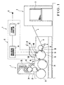
- a liquid transfer apparatus according to the first embodiment of the present invention will be described with reference to Figs. 1 to 3 .
- a sheet-fed rotary printing press 1 comprises a feed device 2 which feeds out sheets 3, i.e., sheet type printing films serving as stacked target liquid transfer bodies, one by one onto a feeder board 4, a corona discharge processing device 5 having dischargers 115 and 116 which subject the surface of each sheet 3 to corona discharge, and a printing unit 7 which prints on the sheet 3 that has undergone a corona discharge process.
- a feed device 2 which feeds out sheets 3, i.e., sheet type printing films serving as stacked target liquid transfer bodies, one by one onto a feeder board 4, a corona discharge processing device 5 having dischargers 115 and 116 which subject the surface of each sheet 3 to corona discharge, and a printing unit 7 which prints on the sheet 3 that has undergone a corona discharge process.
- a feedboard 8 is provided to have a surface inclining downward from the feeder board 4 downstream in the sheet convey direction.
- a registration device (not shown) adjusts the widthwise direction (direction perpendicular to sheet traveling direction) and direction perpendicular to the widthwise direction (the sheet traveling direction) of the sheet 3 fed out from the feeder board 4 onto the feedboard 8. Then, a swing arm shaft pregripper 9 grips the leading edge of the sheet 3 and gripping-changes the sheet 3 to the grippers of a transfer cylinder 10.
- the corona discharge processing device 5 comprises an RF power supply unit 13 which converts the power frequency of a commercial power supply 12 into RF, a high-voltage transformer 14 which boosts the power supply voltage converted into the RF, a dielectric electrode unit 17 to which RF high-voltage power from the high-voltage transformer 14 is supplied, and a stainless-steel conductive ground cylinder 18 (third cylinder) arranged upstream in the sheet convey direction of an impression cylinder 22 and blanket cylinder 23.
- the ground cylinder 18 serves as a guide portion which guides the sheet 3.
- the dielectric electrode unit 17 is arranged at a very small gap from the outer surface of the ground cylinder 18.
- the material of the ground cylinder 18 is not limited to stainless steel but may be any other material as far as it is a conductive metal.
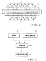
- the dielectric electrode unit 17 comprises dielectric covered electrodes 15 and 16 arranged with different phases in the circumferential direction of the ground cylinder 18.
- the dielectric covered electrodes 15 and 16 respectively comprise a plurality of dielectric covered electrode portions 15a to 15g and a plurality of dielectric covered electrode portions 16a to 16g which are arranged in two rows such that their adjacent ends are in contact with each other in the axial direction (direction perpendicular to the traveling direction of the sheet 3) of the ground cylinder 18.
- Each of the plurality of dielectric covered electrode portions 15a to 15g and each of the plurality of dielectric covered electrode portions 16a to 16g respectively have dischargers 115 and 116 at their centers.
- the ground cylinder 18 is arranged to oppose the transfer cylinder 10. Notches 19 are formed in the peripheral portion of the ground cylinder 18, at positions phase-shifted from each other by 180° in the circumferential direction, to extend in the axial direction of the ground cylinder 18. Gripper devices (to be merely referred to as grippers hereinafter) 20 which grip the leading edge of the sheet 3 are mounted in the notches 19.
- the printing unit 7 comprises a transfer cylinder 21 arranged to oppose the ground cylinder 18, the impression cylinder 22 (first cylinder) arranged to oppose the transfer cylinder 21, the blanket cylinder 23 (second cylinder) arranged to oppose the impression cylinder 22, a plate cylinder 24 which is in contact with the blanket cylinder 23, and an inking device 25 and dampening unit 26 which respectively supply ink and water to the outer surface of the plate cylinder 24.
- Known grippers which gripping-change the sheet 3, the leading edge of which is gripped by the grippers 20 of the ground cylinder 18, are arranged in the peripheral portion of the transfer cylinder 21 at positions phase-shifted from each other by 180° in the circumferential direction of the transfer cylinder 21.
- Known grippers which gripping-change the sheet 3, the leading edge of which is gripped by the grippers of the transfer cylinder 21, are arranged in the peripheral portion of the impression cylinder 22 at positions phase-shifted from each other by 180° in the circumferential direction of the impression cylinder 22.
- Fig. 3 is a block diagram showing the electrical arrangement of the liquid transfer apparatus according to this embodiment.
- a control device 30 is connected to the corona discharge processing device 5, an encoder 28, and a sheet size input device 29.
- the encoder 28 is axially mounted on the end shaft of the transfer cylinder 10 and detects the position of the sheet 3 in the sheet traveling direction which is conveyed as it is gripped by the grippers of the ground cylinder 18.
- the widthwise- and sheet traveling-direction sizes of the sheet 3 are input to the sheet size input device 29.
- the control device 30 controls the on/off operation of corona discharge processing device 5 on the basis of the sheet traveling-direction size of the sheet 3 output from the sheet size input device 29 and the sheet traveling-direction position of the sheet 3 which is output from the encoder 28.
- the control device 30 turns on the corona discharge processing device 5.
- the control device 30 turns off the corona discharge processing device 5.
- the control device 30 selectively turns on/off the dielectric covered electrode portions 15a to 15g and 16a to 16g which constitute the dischargers 15 and 16, respectively. More specifically, if the sheet 3 has a maximum width, the control device 30 turns on all of the dielectric covered electrode portions 15a to 15g and 16a to 16g. If the sheet 3 has a minimum width, the control device 30 turns off the dielectric covered electrode portions 15a, 15b, 15f, 15g, 16a, 16b, 16f, and 16g which are located at the first and second positions from each outer side of the ground cylinder 18 in the axial direction. Namely, only the dielectric covered electrode portions 15c, 15d, 15e, 16c, 16d, and 16e which are located close to the center are turned on.
- the control device 30 turns off the dielectric covered electrode portions 15a, 15g, 16a, and 16g which are located at the first position from each outer side of the ground cylinder 18 in the axial direction, and turns on the dielectric covered electrode portions 15b, 15c, 15d, 15e, 15f, 16b, 16c, 16d, 16e, and 16f which are located closer to the center. As corona discharge is performed for only necessary portions in accordance with the sheet size, unnecessary discharge does not take place, thus saving power.
- the sheet 3 which is fed out onto the feeder board 4 by the feed device 2 is adjusted in the widthwise direction and sheet traveling direction on the feedboard 8. Subsequently, the swing arm shaft pregripper 9 grips the leading edge of the sheet 3 and gripping-changes the sheet 3 to the grippers of the transfer cylinder 10. After being gripping-changed to the grippers of the transfer cylinder 10, the leading edge of the sheet 3 is gripping-changed to the gripper 20 of the ground cylinder 18 at a position where the transfer cylinder 10 opposes the ground cylinder 18. Then, the ground cylinder 18 conveys the sheet 3. During the conveyance by the ground cylinder 18, when the sheet 3 passes through the corona discharge processing device 5, the surface of the sheet 3 undergoes a corona discharge process by the dielectric covered electrodes 15 and 16.
- the leading edge of the corona-discharge-processed sheet 3 is gripping-changed from the gripper 20 of the ground cylinder 18 to the grippers of the transfer cylinder 21 at a position where the ground cylinder 18 opposes the transfer cylinder 21. Then, the sheet 3 is conveyed.
- the sheet 3 conveyed by the transfer cylinder 21 is gripping-changed to the grippers of the impression cylinder 22 at a position where the transfer cylinder 21 opposes the impression cylinder 22.
- the sheet 3 which is conveyed after being gripping-changed to the grippers of the impression cylinder 22 undergoes printing on its corona-discharge-processed surface when it passes through a position where the impression cylinder 22 opposes the blanket cylinder 23.
- the second embodiment of the present invention will be described with reference to Fig. 4 .
- the second embodiment is different from the first embodiment in that roll-type dielectric covered electrodes 35 and 36 replace the dischargers 15 and 16 of the first embodiment.
- the dielectric covered electrodes 35 and 36 are rotated in a direction opposite (clockwise in Fig. 4 ) to the rotation of a ground cylinder 18, i.e., in the same traveling direction as that of a sheet 3 gripped by the grippers of the ground cylinder 18, and at the same peripheral velocity as that of the ground cylinder 18.
- Five rows of dischargers 135 and five rows of dischargers 136 are respectively arranged in the peripheral portions of the dielectric covered electrodes 35 and 36 equidistantly in the circumferential directions.
- the dischargers 135 and 136 of the dielectric covered electrodes 35 and 36 are sequentially turned on each time they oppose the sheet 3 held by the ground cylinder 18, and are turned off each time they cease to oppose the sheet 3 held by the ground cylinder 18.
- the dischargers 135 and 136 are turned off even if they oppose the outer surface o the ground cylinder 18.
- the dielectric covered electrodes 35 and 36 are turned on/off in the widthwise direction in accordance with the size of the sheet 3, in the same manner as in the first embodiment.
- the surface of the sheet 3 traveling as it is gripped by the grippers of the ground cylinder 18 undergoes a corona discharge process by the dischargers 135 and 136 that are sequentially turned on.
- the dischargers 135 and 136 are sequentially turned on as they oppose the sheet 3, and are kept OFF otherwise. Therefore, when compared to the first embodiment in which the discharger 115 is kept ON while it opposes the sheet 3, the durability is improved and the number of times of maintenance operation can be reduced.
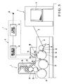
- a heat supply (heating) device 40 which supplies heat to a sheet 3 conveyed by a ground cylinder 18 is provided upstream in the sheet convey direction to be adjacent to a dielectric covered electrode 15 having a discharger 115.
- the corona discharge process by the dielectric covered electrode 15 may be performed in the same manner as in the first and second embodiments. More specifically, the heat supply process by the heat supply device 40 and the corona discharge process by the dielectric covered electrode 15 may be performed selectively in accordance with the state of the sheet 3.
- the first-stage dielectric covered electrode 15 or 35 and the second-stage dielectric covered electrode 16 or 36 are provided for the sake of uniforming the corona discharge process for the sheet 3. However, only the first-stage dielectric covered electrode may be necessary.
- the liquid to transfer onto the sheet 3 is ink, it may be varnish.
- the target liquid transfer body is the sheet 3, it may be a web. In this case, as the ground cylinder 18 need not convey the web, the ground cylinder 18 does not need grippers which hold the web. As a rotary body such as the ground cylinder 18 is not necessary, only a guide device which is conductive at least partially need be provided for guiding the web.
- the target liquid transfer body is not limited to a printing film made of a resin, but may be paper sheet, a foil sheet, or the like.
Landscapes
- Physics & Mathematics (AREA)
- General Physics & Mathematics (AREA)
- Engineering & Computer Science (AREA)
- Mechanical Engineering (AREA)
- Feeding Of Articles By Means Other Than Belts Or Rollers (AREA)
- Supply, Installation And Extraction Of Printed Sheets Or Plates (AREA)
Abstract
Description
- The present invention relates to a liquid transfer apparatus in a printing press or coating device, which modifies the surface of a printing film or sheet before transferring ink or varnish to the printing film or paper sheet.
- In general, a printing film, paper sheet, or the like undergoes a corona discharge process in advance to modify its surface. This is because corona discharge increases the adhesion properties of the ink, thus improving the printing result. It also improves the wear resistance of the surface of the printing film or paper sheet and decreases the amount of static electricity on the printing film, facilitating destaticization after the process.
- If a comparatively long period of time elapses since a corona discharge process until printing, the effect of the corona discharge process lowers. This makes inventory management very difficult for printing films, paper sheets, or the like that have undergone the corona discharge process. Consequently, the printing films, paper sheets, or the like must be purchased in accordance with the printing schedule.
- It is an object of the present invention to provide a liquid transfer apparatus which can recover the effect of a corona discharge process.
- In order to achieve the above object, according to the present invention, there is provided a liquid transfer apparatus comprising a first cylinder supported rotatably, a second cylinder arranged to oppose the first cylinder and supported rotatably, a target liquid transfer body to which a liquid is transferred when the target liquid transfer body travels between the first cylinder and the second cylinder, a guide device which is conductive at least partially and arranged more upstream of the target transfer body in a traveling direction thereof than the first cylinder and the second cylinder and which guides the target liquid transfer body, and a corona discharge processing device which is arranged to oppose the guide device and performing corona discharge for the target liquid transfer body traveling while being guided by the guide device.
-
-
Fig. 1 is a side view of a sheet-fed rotary printing press serving as a liquid transfer apparatus according to the first embodiment of the present invention; -
Fig. 2 is a plan view of a ground cylinder shown inFig. 1 ; -
Fig. 3 is a block diagram showing the electrical arrangement of the liquid transfer apparatus shown inFig. 1 ; -
Fig. 4 is a side view of a sheet-fed rotary printing press according to the second embodiment of the present invention; and -
Fig. 5 is a side view of a sheet-fed rotary printing press according to the third embodiment of the present invention. - A liquid transfer apparatus according to the first embodiment of the present invention will be described with reference to
Figs. 1 to 3 . - As shown in
Fig. 1 , a sheet-fed rotary printing press 1 comprises afeed device 2 which feeds outsheets 3, i.e., sheet type printing films serving as stacked target liquid transfer bodies, one by one onto a feeder board 4, a coronadischarge processing device 5 havingdischargers sheet 3 to corona discharge, and a printing unit 7 which prints on thesheet 3 that has undergone a corona discharge process. - A
feedboard 8 is provided to have a surface inclining downward from the feeder board 4 downstream in the sheet convey direction. A registration device (not shown) adjusts the widthwise direction (direction perpendicular to sheet traveling direction) and direction perpendicular to the widthwise direction (the sheet traveling direction) of thesheet 3 fed out from the feeder board 4 onto thefeedboard 8. Then, a swingarm shaft pregripper 9 grips the leading edge of thesheet 3 and gripping-changes thesheet 3 to the grippers of atransfer cylinder 10. - The corona
discharge processing device 5 comprises an RFpower supply unit 13 which converts the power frequency of acommercial power supply 12 into RF, a high-voltage transformer 14 which boosts the power supply voltage converted into the RF, a dielectric electrode unit 17 to which RF high-voltage power from the high-voltage transformer 14 is supplied, and a stainless-steel conductive ground cylinder 18 (third cylinder) arranged upstream in the sheet convey direction of animpression cylinder 22 andblanket cylinder 23. Theground cylinder 18 serves as a guide portion which guides thesheet 3. The dielectric electrode unit 17 is arranged at a very small gap from the outer surface of theground cylinder 18. The material of theground cylinder 18 is not limited to stainless steel but may be any other material as far as it is a conductive metal. - The dielectric electrode unit 17 comprises dielectric covered
electrodes ground cylinder 18. As shown inFig. 2 , the dielectric coveredelectrodes electrode portions 15a to 15g and a plurality of dielectric coveredelectrode portions 16a to 16g which are arranged in two rows such that their adjacent ends are in contact with each other in the axial direction (direction perpendicular to the traveling direction of the sheet 3) of theground cylinder 18. Each of the plurality of dielectric coveredelectrode portions 15a to 15g and each of the plurality of dielectric coveredelectrode portions 16a to 16g respectively havedischargers - The
ground cylinder 18 is arranged to oppose thetransfer cylinder 10.Notches 19 are formed in the peripheral portion of theground cylinder 18, at positions phase-shifted from each other by 180° in the circumferential direction, to extend in the axial direction of theground cylinder 18. Gripper devices (to be merely referred to as grippers hereinafter) 20 which grip the leading edge of thesheet 3 are mounted in thenotches 19. - The printing unit 7 comprises a
transfer cylinder 21 arranged to oppose theground cylinder 18, the impression cylinder 22 (first cylinder) arranged to oppose thetransfer cylinder 21, the blanket cylinder 23 (second cylinder) arranged to oppose theimpression cylinder 22, aplate cylinder 24 which is in contact with theblanket cylinder 23, and aninking device 25 anddampening unit 26 which respectively supply ink and water to the outer surface of theplate cylinder 24. - Known grippers (not shown) which gripping-change the
sheet 3, the leading edge of which is gripped by thegrippers 20 of theground cylinder 18, are arranged in the peripheral portion of thetransfer cylinder 21 at positions phase-shifted from each other by 180° in the circumferential direction of thetransfer cylinder 21. Known grippers (not shown) which gripping-change thesheet 3, the leading edge of which is gripped by the grippers of thetransfer cylinder 21, are arranged in the peripheral portion of theimpression cylinder 22 at positions phase-shifted from each other by 180° in the circumferential direction of theimpression cylinder 22. -
Fig. 3 is a block diagram showing the electrical arrangement of the liquid transfer apparatus according to this embodiment. As shown inFig. 3 , acontrol device 30 is connected to the coronadischarge processing device 5, anencoder 28, and a sheetsize input device 29. Theencoder 28 is axially mounted on the end shaft of thetransfer cylinder 10 and detects the position of thesheet 3 in the sheet traveling direction which is conveyed as it is gripped by the grippers of theground cylinder 18. Upon key operation of the operator, the widthwise- and sheet traveling-direction sizes of thesheet 3 are input to the sheetsize input device 29. Thecontrol device 30 controls the on/off operation of coronadischarge processing device 5 on the basis of the sheet traveling-direction size of thesheet 3 output from the sheetsize input device 29 and the sheet traveling-direction position of thesheet 3 which is output from theencoder 28. - This will be described in detail. When the leading edge of the
sheet 3 which is conveyed as it is gripped by the grippers of theground cylinder 18 reaches the dielectric coveredelectrode 16, that is, when the sheet on theground cylinder 18 has opposed the dielectric coveredelectrode 16, thecontrol device 30 turns on the coronadischarge processing device 5. When the trailing edge of thesheet 3 passes thedischarger 16, that is, when the outer surface of theground cylinder 18 has opposed the dielectric coveredelectrode 16, thecontrol device 30 turns off the coronadischarge processing device 5. - Similarly, when the leading edge of the
sheet 3 which is conveyed as it is gripped by the grippers of theground cylinder 18 reaches the dielectric coveredelectrode 15, that is, when the sheet on theground cylinder 18 has opposed the dielectric coveredelectrode 16, thecontrol device 30 turns on the coronadischarge processing device 5. When the trailing edge of thesheet 3 passes thedischarger 15, that is, when the outer surface of theground cylinder 18 has opposed the dielectric coveredelectrode 16, thecontrol device 30 turns off the coronadischarge processing device 5. - On the basis of the widthwise-direction size of the
sheet 3 input from the sheetsize input device 29, thecontrol device 30 selectively turns on/off the dielectric coveredelectrode portions 15a to 15g and 16a to 16g which constitute thedischargers sheet 3 has a maximum width, thecontrol device 30 turns on all of the dielectric coveredelectrode portions 15a to 15g and 16a to 16g. If thesheet 3 has a minimum width, thecontrol device 30 turns off the dielectric coveredelectrode portions ground cylinder 18 in the axial direction. Namely, only the dielectric coveredelectrode portions - If the sheet has a width between the maximum width and minimum width, in accordance with the size, the
control device 30 turns off the dielectric coveredelectrode portions ground cylinder 18 in the axial direction, and turns on the dielectric coveredelectrode portions - Printing operation in the sheet-fed rotary printing press having the above arrangement will be described. The
sheet 3 which is fed out onto the feeder board 4 by thefeed device 2 is adjusted in the widthwise direction and sheet traveling direction on thefeedboard 8. Subsequently, the swingarm shaft pregripper 9 grips the leading edge of thesheet 3 and gripping-changes thesheet 3 to the grippers of thetransfer cylinder 10. After being gripping-changed to the grippers of thetransfer cylinder 10, the leading edge of thesheet 3 is gripping-changed to thegripper 20 of theground cylinder 18 at a position where thetransfer cylinder 10 opposes theground cylinder 18. Then, theground cylinder 18 conveys thesheet 3. During the conveyance by theground cylinder 18, when thesheet 3 passes through the coronadischarge processing device 5, the surface of thesheet 3 undergoes a corona discharge process by the dielectric coveredelectrodes - The leading edge of the corona-discharge-processed
sheet 3 is gripping-changed from thegripper 20 of theground cylinder 18 to the grippers of thetransfer cylinder 21 at a position where theground cylinder 18 opposes thetransfer cylinder 21. Then, thesheet 3 is conveyed. Thesheet 3 conveyed by thetransfer cylinder 21 is gripping-changed to the grippers of theimpression cylinder 22 at a position where thetransfer cylinder 21 opposes theimpression cylinder 22. Thesheet 3 which is conveyed after being gripping-changed to the grippers of theimpression cylinder 22 undergoes printing on its corona-discharge-processed surface when it passes through a position where theimpression cylinder 22 opposes theblanket cylinder 23. - In this manner, since the corona discharge process is performed immediately before printing, its effect is sufficiently maintained when the ink is to be transferred onto the
sheet 3. Hence, the adhesion properties of the ink increase, the wear resistance is improved, and the destaticization properties are improved, leading to an improved quality. As thesheets 3 need not be purchased in accordance with the printing schedule, inventory management of thesheets 3 becomes possible, and a sudden printing order can sufficiently be accepted. - The second embodiment of the present invention will be described with reference to
Fig. 4 . The second embodiment is different from the first embodiment in that roll-type dielectric coveredelectrodes dischargers electrodes Fig. 4 ) to the rotation of aground cylinder 18, i.e., in the same traveling direction as that of asheet 3 gripped by the grippers of theground cylinder 18, and at the same peripheral velocity as that of theground cylinder 18. Five rows ofdischargers 135 and five rows ofdischargers 136 are respectively arranged in the peripheral portions of the dielectric coveredelectrodes - In this arrangement, as the dielectric covered
electrodes dischargers electrodes sheet 3 held by theground cylinder 18, and are turned off each time they cease to oppose thesheet 3 held by theground cylinder 18. Thus, depending on the sheet traveling-direction size of thesheet 3 input from a sheetsize input device 29 and the sheet position input from anencoder 28, when thesheet 3 does not oppose the dielectric coveredelectrodes dischargers ground cylinder 18. Depending on the widthwise-direction size of thesheet 3 input from the sheetsize input device 29, the dielectric coveredelectrodes sheet 3, in the same manner as in the first embodiment. - Therefore, the surface of the
sheet 3 traveling as it is gripped by the grippers of theground cylinder 18 undergoes a corona discharge process by thedischargers sheet 3 conveyed by theground cylinder 18 travels such that its trailing edge is levitated from the outer surface of theground cylinder 18, no friction occurs when the trailing edge of thesheet 3 comes into contact with the dielectric coveredelectrodes sheet 3 will not be damaged. Thedischargers sheet 3, and are kept OFF otherwise. Therefore, when compared to the first embodiment in which thedischarger 115 is kept ON while it opposes thesheet 3, the durability is improved and the number of times of maintenance operation can be reduced. - The third embodiment of the present invention will be described with reference to
Fig. 5 . According to the third embodiment, a heat supply (heating)device 40 which supplies heat to asheet 3 conveyed by aground cylinder 18 is provided upstream in the sheet convey direction to be adjacent to a dielectric coveredelectrode 15 having adischarger 115. - In this arrangement, heat is supplied to the
sheet 3 in advance before thesheet 3 undergoes a corona discharge process by the dielectric coveredelectrode 15. This further improves the effect of the corona discharge process by the dielectric coveredelectrode 15. This is effective when thesheets 3 stacked on afeed device 2 have undergone the corona discharge process in advance and need not undergo the corona discharge process by the dielectric coveredelectrode 15. More specifically, the corona discharge process performed on thesheet 3 can be reactivated by only supplying heat by theheat supply device 40 to thesheet 3 which is conveyed by theground cylinder 18. - If no heat need be supplied to the
sheet 3, only the corona discharge process by the dielectric coveredelectrode 15 may be performed in the same manner as in the first and second embodiments. More specifically, the heat supply process by theheat supply device 40 and the corona discharge process by the dielectric coveredelectrode 15 may be performed selectively in accordance with the state of thesheet 3. - In the above embodiments, the first-stage dielectric covered
electrode electrode sheet 3. However, only the first-stage dielectric covered electrode may be necessary. - Although the liquid to transfer onto the
sheet 3 is ink, it may be varnish. Although the target liquid transfer body is thesheet 3, it may be a web. In this case, as theground cylinder 18 need not convey the web, theground cylinder 18 does not need grippers which hold the web. As a rotary body such as theground cylinder 18 is not necessary, only a guide device which is conductive at least partially need be provided for guiding the web. The target liquid transfer body is not limited to a printing film made of a resin, but may be paper sheet, a foil sheet, or the like.
Claims (10)
- A liquid transfer apparatus characterized by comprising:a first cylinder (22) supported rotatably;a second cylinder (23) arranged to oppose said first cylinder and supported rotatably;a target liquid transfer body (3) to which a liquid is transferred when said target liquid transfer body travels between said first cylinder and said second cylinder;a guide device (18) which is conductive at least partially and arranged more upstream of said target transfer body in a traveling direction thereof than said first cylinder and said second cylinder and which guides said target liquid transfer body; anda corona discharge processing device (5) which is arranged to oppose said guide device and performs corona discharge for said target liquid transfer body traveling by being guided by said guide device.
- An apparatus according to claim 1,
wherein said target liquid transfer body comprises a sheet, and
said guide device comprises a third cylinder including a holding member for holding the sheet and supported rotatably. - An apparatus according to claim 1,
wherein said corona discharge processing device includes a plurality of dielectric covered electrodes (15, 15a - 15g, 16, 16a - 16g) in a direction perpendicular to the traveling direction of said target liquid transfer body,
said plurality of dielectric covered electrodes being selectively turned on/off in accordance with a size of said target liquid transfer body in a direction perpendicular to the traveling direction thereof. - An apparatus according to claim 3, further comprising
size input means (29) for inputting the size of said target liquid transfer body in the direction perpendicular to the traveling direction thereof, and
control means (30) for selectively turning on/off said plurality of dielectric covered electrodes in accordance with the size of said target liquid transfer body output from said size input means. - An apparatus according to claim 1,
wherein said corona discharge processing device includes a plurality of dielectric covered electrodes (15, 15a - 15g, 16, 16a - 16g) arranged relative to said target liquid transfer body in the traveling direction of said target liquid transfer body,
said plurality of dielectric covered electrodes being selectively turned on/off in accordance with a size of said target liquid transfer body in the traveling direction thereof and a position of said target liquid transfer body in the traveling direction thereof. - An apparatus according to claim 5, further comprising
size input means (29) for inputting the size of said target liquid transfer body in the traveling direction thereof,
position detection means (28) for detecting the position of said target liquid transfer body in the traveling direction thereof, and
control means (30) for selectively turning on/off said plurality of dielectric covered electrodes in accordance with the size of said target liquid transfer body in the traveling direction thereof output from said size input means and the position of said target liquid transfer body output from said position detection means. - An apparatus according to claim 1, wherein said corona discharge processing device includes a plurality of dielectric covered electrodes arranged in the traveling direction of said target liquid transfer body.
- An apparatus according to claim 1, wherein said corona discharge processing device includes a plurality of dielectric covered electrodes arranged in a peripheral portion of a rotatably supported rotary body at a predetermined interval in a rotational direction of said rotary body.
- An apparatus according to claim 1, further comprising
a heating device (40) arranged to oppose said guide device to heat said target liquid transfer body guided by said guide device,
wherein at least one of said heating device and said corona discharge processing device is actuated in accordance with a state of said target liquid transfer body. - An apparatus according to claim 1, wherein said guide device includes a conductive member toward which said corona discharge processing device discharges through said target liquid transfer body.
Applications Claiming Priority (1)
| Application Number | Priority Date | Filing Date | Title |
|---|---|---|---|
| JP2006321965A JP2008132723A (en) | 2006-11-29 | 2006-11-29 | Liquid transfer device |
Publications (1)
| Publication Number | Publication Date |
|---|---|
| EP1927473A1 true EP1927473A1 (en) | 2008-06-04 |
Family
ID=39203114
Family Applications (1)
| Application Number | Title | Priority Date | Filing Date |
|---|---|---|---|
| EP07022325A Withdrawn EP1927473A1 (en) | 2006-11-29 | 2007-11-16 | Liquid transfer apparatus |
Country Status (4)
| Country | Link |
|---|---|
| US (1) | US20080260429A1 (en) |
| EP (1) | EP1927473A1 (en) |
| JP (1) | JP2008132723A (en) |
| CN (1) | CN101190595B (en) |
Citations (7)
| Publication number | Priority date | Publication date | Assignee | Title |
|---|---|---|---|---|
| GB1080649A (en) * | 1963-11-21 | 1967-08-23 | Nat Distillers Chem Corp | Method to increase adhesion of a polyolefin coating to substrates |
| GB1080233A (en) * | 1963-09-09 | 1967-08-23 | Celanese Corp | Surface treatment of sheet materials and articles |
| DE1257414B (en) * | 1964-10-20 | 1967-12-28 | Dietrich Erben Dipl Ing | Device for treating the surface of thin-walled plastic bodies |
| US4208965A (en) * | 1977-03-25 | 1980-06-24 | Helmut Eichler | Method for electrostatic assistance in printing processes, and printing machines having electrostatic substrate contact pressure |
| WO2002016136A1 (en) * | 2000-08-25 | 2002-02-28 | Man Roland Druckmaschinen Ag | Method and device for coating printed products |
| DE10232255A1 (en) * | 2002-07-17 | 2004-02-05 | Koenig & Bauer Ag | Rotary print machine has a corona discharge print mechanism that is configured so that its print cylinder forms the counter electrode and so that it can be used at different stages along the processing line |
| DE102006019792A1 (en) * | 2005-05-04 | 2006-11-09 | Ist Metz Gmbh | Corona treatment device for flat sheet printing material, has gas stream blown on to flat material so that latter lies flat on cylindrical surface of transport electrode |
Family Cites Families (8)
| Publication number | Priority date | Publication date | Assignee | Title |
|---|---|---|---|---|
| BE600113A (en) * | 1960-02-12 | 1900-01-01 | ||
| DE2753750C2 (en) * | 1977-12-02 | 1982-12-23 | Hoechst Ag, 6000 Frankfurt | Device for the surface treatment of foil webs by means of electrical corona discharge |
| EP0138816B1 (en) * | 1983-02-07 | 1987-12-09 | Gravure Association of America, Inc. | Improved method and apparatus for direct charging of the surface of an impression roll of an electrostatic assist gravure press |
| JPH01136749A (en) * | 1987-11-25 | 1989-05-30 | Mitsubishi Heavy Ind Ltd | Paper powder removing device of printing apparatus |
| DE3828753C2 (en) * | 1988-08-25 | 1994-05-19 | Heidelberger Druckmasch Ag | Device for drying printed products in a printing press |
| JP3779952B2 (en) * | 2002-04-17 | 2006-05-31 | リョービ株式会社 | Printing unit for sheet-fed press |
| DE10312153A1 (en) * | 2003-03-17 | 2004-10-07 | Ebe Hesterman | Machine for sheet-fed rotary printing or sheet coating |
| DE102005038834A1 (en) * | 2005-08-17 | 2007-02-22 | Man Roland Druckmaschinen Ag | Sheet fed printing machine, for printing e.g. print sheet, has corona treatment devices putting corona treatment on upper side and lower side of print sheet, and scaling device combining sheet to scaling stream supplied via disposing table |
-
2006
- 2006-11-29 JP JP2006321965A patent/JP2008132723A/en active Pending
-
2007
- 2007-11-14 US US11/985,403 patent/US20080260429A1/en not_active Abandoned
- 2007-11-16 EP EP07022325A patent/EP1927473A1/en not_active Withdrawn
- 2007-11-28 CN CN2007101928900A patent/CN101190595B/en not_active Expired - Fee Related
Patent Citations (8)
| Publication number | Priority date | Publication date | Assignee | Title |
|---|---|---|---|---|
| GB1080233A (en) * | 1963-09-09 | 1967-08-23 | Celanese Corp | Surface treatment of sheet materials and articles |
| GB1080649A (en) * | 1963-11-21 | 1967-08-23 | Nat Distillers Chem Corp | Method to increase adhesion of a polyolefin coating to substrates |
| DE1257414B (en) * | 1964-10-20 | 1967-12-28 | Dietrich Erben Dipl Ing | Device for treating the surface of thin-walled plastic bodies |
| US4208965A (en) * | 1977-03-25 | 1980-06-24 | Helmut Eichler | Method for electrostatic assistance in printing processes, and printing machines having electrostatic substrate contact pressure |
| US4208965B1 (en) * | 1977-03-25 | 1983-01-10 | ||
| WO2002016136A1 (en) * | 2000-08-25 | 2002-02-28 | Man Roland Druckmaschinen Ag | Method and device for coating printed products |
| DE10232255A1 (en) * | 2002-07-17 | 2004-02-05 | Koenig & Bauer Ag | Rotary print machine has a corona discharge print mechanism that is configured so that its print cylinder forms the counter electrode and so that it can be used at different stages along the processing line |
| DE102006019792A1 (en) * | 2005-05-04 | 2006-11-09 | Ist Metz Gmbh | Corona treatment device for flat sheet printing material, has gas stream blown on to flat material so that latter lies flat on cylindrical surface of transport electrode |
Also Published As
| Publication number | Publication date |
|---|---|
| CN101190595B (en) | 2010-06-16 |
| JP2008132723A (en) | 2008-06-12 |
| CN101190595A (en) | 2008-06-04 |
| US20080260429A1 (en) | 2008-10-23 |
Similar Documents
| Publication | Publication Date | Title |
|---|---|---|
| EP4209349B1 (en) | Sheet processing machine, use of the sheet processing machine, method for conveying sheets and use of sheet guiding elements containing deionization devices | |
| EP1867477B2 (en) | A printing press with an intaglio printing unit, a stencil printing unit and a drying device | |
| JP2013099952A (en) | Intaglio printing press system for recto-verso intaglio-printing of sheets for production of banknotes and like securities | |
| EP2468506B1 (en) | Identification mark printing machine | |
| DE102019118565B4 (en) | Sheet processing machine and method for conveying sheets | |
| CN104718080B (en) | Combined printing machine | |
| US10427398B2 (en) | Security printing press having at least one printing assembly, and method for operating a squeegee device | |
| EP2657036A1 (en) | Sheet reversing device | |
| US20080260429A1 (en) | Liquid transfer apparatus | |
| CN100491123C (en) | Blowing device for printing presses | |
| CN120225361B (en) | Sheet-fed rotary printing press with electrode unit | |
| JP4450890B2 (en) | Sheet-fed rotary printing press | |
| US11207880B2 (en) | Device, method and printing press for multiple printing of printing substrate sheets | |
| US20150210061A1 (en) | Numbering and imprinting machine and printing press utilizing the same | |
| DE102023125604A1 (en) | Sheet-fed printing press with charging and discharging device | |
| DE102023125603A1 (en) | Sheet-fed printing press with charging device on the impression cylinder and discharging device | |
| DE102023125606A1 (en) | Sheet-fed printing press with two unloading devices | |
| US6722278B2 (en) | Sheet-fed rotary printing press | |
| JP2007050692A (en) | Sheet printer | |
| DE102019118571B4 (en) | Sheet processing machine and method for conveying sheets | |
| US793115A (en) | Sheet-controlling means. | |
| EP3434482B1 (en) | Double-sided varnishing apparatus | |
| DE102010028701A1 (en) | Sheet guiding device for use as e.g. feeder for sheet fed press, has guide surface for guiding sheets during transportation of sheets, where electrostatic adhesion or repulsion of sheets is influenced at surface by lifts | |
| JP2016129936A (en) | Printer | |
| JP2016129937A (en) | Printer |
Legal Events
| Date | Code | Title | Description |
|---|---|---|---|
| PUAI | Public reference made under article 153(3) epc to a published international application that has entered the european phase |
Free format text: ORIGINAL CODE: 0009012 |
|
| AK | Designated contracting states |
Kind code of ref document: A1 Designated state(s): AT BE BG CH CY CZ DE DK EE ES FI FR GB GR HU IE IS IT LI LT LU LV MC MT NL PL PT RO SE SI SK TR |
|
| AX | Request for extension of the european patent |
Extension state: AL BA HR MK RS |
|
| 17P | Request for examination filed |
Effective date: 20081112 |
|
| 17Q | First examination report despatched |
Effective date: 20081218 |
|
| AKX | Designation fees paid |
Designated state(s): AT BE BG CH CY CZ DE DK EE ES FI FR GB GR HU IE IS IT LI LT LU LV MC MT NL PL PT RO SE SI SK TR |
|
| STAA | Information on the status of an ep patent application or granted ep patent |
Free format text: STATUS: THE APPLICATION IS DEEMED TO BE WITHDRAWN |
|
| 18D | Application deemed to be withdrawn |
Effective date: 20090630 |