EP1927450A1 - Process for producing tire and tire vulcanization mold - Google Patents
Process for producing tire and tire vulcanization mold Download PDFInfo
- Publication number
- EP1927450A1 EP1927450A1 EP06810247A EP06810247A EP1927450A1 EP 1927450 A1 EP1927450 A1 EP 1927450A1 EP 06810247 A EP06810247 A EP 06810247A EP 06810247 A EP06810247 A EP 06810247A EP 1927450 A1 EP1927450 A1 EP 1927450A1
- Authority
- EP
- European Patent Office
- Prior art keywords
- tire
- bead
- rigid core
- pair
- mold
- Prior art date
- Legal status (The legal status is an assumption and is not a legal conclusion. Google has not performed a legal analysis and makes no representation as to the accuracy of the status listed.)
- Granted
Links
Images


Classifications
-
- B—PERFORMING OPERATIONS; TRANSPORTING
- B29—WORKING OF PLASTICS; WORKING OF SUBSTANCES IN A PLASTIC STATE IN GENERAL
- B29D—PRODUCING PARTICULAR ARTICLES FROM PLASTICS OR FROM SUBSTANCES IN A PLASTIC STATE
- B29D30/00—Producing pneumatic or solid tyres or parts thereof
- B29D30/06—Pneumatic tyres or parts thereof (e.g. produced by casting, moulding, compression moulding, injection moulding, centrifugal casting)
- B29D30/0601—Vulcanising tyres; Vulcanising presses for tyres
- B29D30/0661—Rigid cores therefor, e.g. annular or substantially toroidal cores
-
- B—PERFORMING OPERATIONS; TRANSPORTING
- B29—WORKING OF PLASTICS; WORKING OF SUBSTANCES IN A PLASTIC STATE IN GENERAL
- B29D—PRODUCING PARTICULAR ARTICLES FROM PLASTICS OR FROM SUBSTANCES IN A PLASTIC STATE
- B29D30/00—Producing pneumatic or solid tyres or parts thereof
- B29D30/06—Pneumatic tyres or parts thereof (e.g. produced by casting, moulding, compression moulding, injection moulding, centrifugal casting)
- B29D30/08—Building tyres
- B29D30/10—Building tyres on round cores, i.e. the shape of the core is approximately identical with the shape of the completed tyre
-
- B—PERFORMING OPERATIONS; TRANSPORTING
- B29—WORKING OF PLASTICS; WORKING OF SUBSTANCES IN A PLASTIC STATE IN GENERAL
- B29D—PRODUCING PARTICULAR ARTICLES FROM PLASTICS OR FROM SUBSTANCES IN A PLASTIC STATE
- B29D30/00—Producing pneumatic or solid tyres or parts thereof
- B29D30/06—Pneumatic tyres or parts thereof (e.g. produced by casting, moulding, compression moulding, injection moulding, centrifugal casting)
- B29D30/0601—Vulcanising tyres; Vulcanising presses for tyres
- B29D30/0606—Vulcanising moulds not integral with vulcanising presses
- B29D2030/0607—Constructional features of the moulds
- B29D2030/062—Means for sealing the tyre against the mould in the bead areas
- B29D2030/0621—Means for sealing the tyre against the mould in the bead areas to seal the bead portions against the mould i.e. by using pressing devices
- B29D2030/0627—Means for sealing the tyre against the mould in the bead areas to seal the bead portions against the mould i.e. by using pressing devices the pressing devices being ring-shaped
Definitions
- This invention relates to a method for manufacturing a tire and a tire curing mold utilized for this method, the method comprising steps of: forming green tire by assembling tire components on a rigid core having an outer surface corresponding to the inner surface shape of a product tire, preheating said green tire with the rigid core attached, and curing said green tire in a curing mold, for manufacturing a tire having carcass turn-up structure around a bead core, especially relates to the method and the mold capable of preventing possible bead portion failure due to the temperature rise while preheating the green tire.
- a tire manufacturing method utilizing a rigid core it is widely performed to preheat a green tire, for example, by keeping it in a preheating station where the temperature is maintained at a predetermined degree, before it is placed into the curing mold, in order to shorten curing time.
- This is performed because in case of the process without preheating, it is necessary to heat up not only a tire but also a rigid core having a large heat capacity, in the curing mold, and the additional heating for a rigid core requires excessive curing time.
- a green tire finished with its forming is transferred into a curing mold through the preheating station together with the rigid core attached, then cured in the curing mold, and afterwards, a cured tire is unloaded from a rigid core, then shipped through inspection process, while the rigid core is left to be cooled for the next green tire building,
- Patent Document 1 Japanese Patent Application Laid-open No. 2000-084937 ( JP2000084937 A )
- Patent Document 2 Japanese Patent Application Laid-open No. 2002-264134 ( JP2002264134 A )
- Fig 1 is a cross-sectional view showing an example of a construction of a green tire manufactured according to the abovementioned method.
- a green tire 90 is configured so that a radial carcass composed of at least one carcass ply 91 is disposed extending between a pair of bead cores 95, and a belt 96 and a tread rubber 97 are disposed outside the radial carcass.
- a structure wherein a pair of side portions 93 of the carcass ply are turned up around the bead cores 95, and stuck to the main portion 92 of the carcass ply extending between a pair of bead cores 95, is widely adopted.
- a cord constituting the carcass ply consists of woven organic fiber, or woven steel filament especially for a heavy loading tire.
- This invention has been conceived in view of such a problem, and it is, therefore, an object of the present invention to provide a method of manufacturing tires and curing mold for said method, capable of preventing such a failure that the turned-up portion and the main portion of the carcass are moved apart from each other.
- the present invention provides a method of manufacturing a tire having at least one carcass ply turned up around a pair of bead cores, comprising steps of: forming a green tire by assembling tire components on a rigid core having an outer surface corresponding to the inner surface shape of a product tire, preheating said green tire together with the rigid core attached, and curing said green tire in a curing mold, wherein said method comprises a step of assembling a pair of bead-holding rings to the rigid core prior to said preheating step; each bead-holding ring holding a corresponding bead portion of the green tire from the lateral outside.
- the present invention further provides a method of manufacturing a tire according to the invention in item (1), comprising a step of placing the green tire in the curing mold together with the bead-holding rings attached on the rigid core.
- the present invention further provides a method of manufacturing tires according to the invention in item (1) or (2), wherein the step of assembling the pair of bead-holding rings to the rigid core is performed by connecting the pair of bead-holding rings each other.
- the present invention further provides a tire curing mold to be utilized for the method of manufacturing a tire in any one of the inventions from item (1) to (3), comprising a tread-mold specifying an outer surface shape of tire tread portion, the tread-mold consisting of plural segments disposed in the tire circumferential direction, a pair of sidewall-molds specifying an outer surface shape of tire sidewall portions, and a pair of bead-molds specifying an outer surface shape of tire bead portions, said each bead-mold consisting of said bead-holding ring.
- a tire curing mold to be utilized for the method of manufacturing a tire in any one of the inventions from item (1) to (3), comprising a tread-mold specifying an outer surface shape of tire tread portion, the tread-mold consisting of plural segments disposed in the tire circumferential direction, a pair of sidewall-molds specifying an outer surface shape of tire sidewall portions, and a pair of bead-molds specifying an outer surface shape of tire
- a pair of bead-holding rings are assembled to the rigid core prior to said preheating step, wherein each bead-holding ring holds a corresponding bead portion from the lateral outside, so that a pair of bead-holding rings restrain the deformation of the bead portions even while they are being heated, as a result, it can be prevented the side portions being moved apart from the main portion of the carcass ply.
- the green tire is placed in the curing mold together with the bead-holding rings attached on the rigid core, so that a pair of bead-holding rings restrict deformation of the bead portions until deformation for restoration in the steel cords of the side portions of the carcass ply is kept under restraint by the adjacent cured rubber at the end of tire curing process, therefore, it is capable for preventing the side portions of the carcass ply being moved apart from the main portion.
- assembling the pair of bead-holding rings to the rigid core is being made by connecting the pair of bead-holding rings each other, so that bead potion holding can be performed assuredly.
- a tire curing mold comprises a tread-mold specifying an outer surface shape of tire tread portion, the tread-mold consisting of plural segments disposed in the tire circumferential direction, a pair of sidewall-molds specifying an outer surface shape of tire sidewall portions, and a pair of bead-molds specifying an outer surface shape of tire bead portions, said each bead-mold consisting of said bead-holding ring, so that deformation in the bead portions can be restrained by means of bead-holding rings, and additionally, tire outer surface can be molded to be continuous by configuring the sidewall-molds so as not to interfere with bead-holding rings.
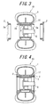
- Fig.3 - Fig.7 are schematic cross-sectional view of a tire at each stage in tire processing, to explain the tire manufacturing method of the present invention.
- a green tire 10 is formed at a tire building station, by applying such tire components as an inner liner, bead cores, carcass ply(s), belt plies, sidewall rubbers, or, a tread rubber, in sequence onto a rigid core 5 which is installed on the rotational shaft of a tire building machine, through the attachment 6 as shown in Fig.3 .
- each of bead-holding rings which have been standing by at the lateral outside of the rigid core 1 is transferred towards the lateral center of the rigid core 1 until it touches a corresponding bead portion of the green tire 10, then halted there.
- a plurality of double-end studs 3 with male screw portions 3a on both ends being installed circumferentially, while holes 2a being formed for letting these studs 3 through, it is capable reliably to fix a pair of bead-holding rings to the rigid core 10 with corresponding portions of a tire therebetween as shown in Fig. 4 , by screwing nuts 7 to the male screw portions 3a protruding out of the holes 2a towards the lateral outside, after a pair of bead-holding rings 2 touches bead portions of the tire respectively.
- the green tire 10 is taken out of the rotational shaft of a tire building machine and transferred to a green tire preheating station 20.
- a customizes transferring machine or a handling robot can be used for this transfer.
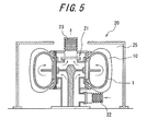
- the rigid core 1 is set onto a preheating apparatus 21 installed in a preheating chamber 25 as shown Fig. 5 .
- the temperature in the preheating chamber 25 is controlled to be higher than the room temperature and preheating apparatus 21 being configured so that the air with high temperature taken from a warm air inlet 22 circulates inside the rigid core 1, then goes out to a warm air outlet 23, both the green tire 10 and the rigid core 1 are heated up to the predetermined temperature.
- the green tire 10 is kept attached on the rigid core 1 during all the period while they are preheated at the preheating station 20, and the green tire finished with preheating is taken out of the preheating apparatus 21 together with the rigid core 1 attached, and transferred to the tire curing station.
- the curing mold 30 specifying the outer surface of the tire 10 and transmitting the heat to the green tire 10 from the outside
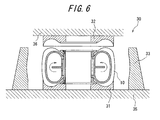
- the curing mold 30 consists of, as shown in cross-sectional view in Fig. 6 , a pair of sidewall-molds 31, 32 specifying an outer surface shape of the tire sidewall portions, a tread-mold 33 specifying an outer surface shape of the tire tread portion, and a pair of bead-mold specifying an outer surface shape of the tire bead portions.
- a pair of bead-holding rings 2 as a pair of bead-molds, since a green tire 10 is transferred to the curing station together with a pair of bead-holding rings 2 attached.
- the sidewall-molds 31, 32 are installed to a lower plate 35 and a upper plate 36 which are displaced closer and away against each other, respectively, and the circumferentially arranged segments 33a constituting the tread-mold 33 are capable to relocate in the radial direction on the lower plate 35.
- sidewall-molds 31, 32, tread-mold 33, and the bead-holding rings 2 are placed apart from each other, and the curing mold is capable of containing a green tire transferred therein, and at this state, a green tire transferred form the preheating station 20 is placed on the lower sidewall-mold.
- the curing mold 30 is closed by displacing sidewall-molds 31, 32, tread-mold 33, and bead-holding rings 2 closer to the each other and touching them each other, and then the curing process is started.
- the curing mold is again opened, and a cured tire including bead-holding rings 2, and the rigid core 1 is taken out of the curing mold 30, then at a rigid-core-assembling-disassembling station, bead-holding rings 2 are firstly disassembled out of the cured tire 1, then the rigid core 1 is taken out of the cured tire 10 after it is disassembled into pieces.
- a cured tire is transferred to the inspection process, while the disassembled rigid core 1 is reassembled at the rigid-core-assembling-disassembling station and the transferred to the tire building station together with the bead-holding rings 2 which have been already disassembled, in order to be ready fore next green tire forming.
- this invention since this invention restrict the deformation of tire bead portions by means of the bead-holding rings 2 from the beginning of preheating process to the end of the curing process, it is capable of preventing that the side portions of the carcass being moved apart from the main portion.
Landscapes
- Engineering & Computer Science (AREA)
- Mechanical Engineering (AREA)
- Moulds For Moulding Plastics Or The Like (AREA)
- Heating, Cooling, Or Curing Plastics Or The Like In General (AREA)
Abstract
Description
- This invention relates to a method for manufacturing a tire and a tire curing mold utilized for this method, the method comprising steps of: forming green tire by assembling tire components on a rigid core having an outer surface corresponding to the inner surface shape of a product tire, preheating said green tire with the rigid core attached, and curing said green tire in a curing mold, for manufacturing a tire having carcass turn-up structure around a bead core, especially relates to the method and the mold capable of preventing possible bead portion failure due to the temperature rise while preheating the green tire.
- There are already known tire manufacturing methods which comprise steps of; forming a green tire by assembling tire components on a rigid core having an outer surface corresponding to the inner surface shape of a product tire, placing said green tire in a curing mold and curing it (See Patent Document 1 and 2), and according to these methods, an extremely precise tire can be obtained, since every tire components are assembled in the same shape as they are in the product tire from the beginning of green tire forming, therefore, a tire has no residual stress compared to a tire manufactured by a method wherein a green tire formed into a different shape from that of the product tire is afterwards deformed into the shape of the product tire.
- In a tire manufacturing method utilizing a rigid core, as explained above, it is widely performed to preheat a green tire, for example, by keeping it in a preheating station where the temperature is maintained at a predetermined degree, before it is placed into the curing mold, in order to shorten curing time. This is performed because in case of the process without preheating, it is necessary to heat up not only a tire but also a rigid core having a large heat capacity, in the curing mold, and the additional heating for a rigid core requires excessive curing time.
- In the tire manufacturing method aforementioned, a green tire finished with its forming is transferred into a curing mold through the preheating station together with the rigid core attached, then cured in the curing mold, and afterwards, a cured tire is unloaded from a rigid core, then shipped through inspection process, while the rigid core is left to be cooled for the next green tire building,
- Patent Document 1: Japanese Patent Application Laid-open No.
2000-084937 JP2000084937 A - Patent Document 2: Japanese Patent Application Laid-open No.
2002-264134 JP2002264134 A -
Fig 1 is a cross-sectional view showing an example of a construction of a green tire manufactured according to the abovementioned method. Agreen tire 90 is configured so that a radial carcass composed of at least onecarcass ply 91 is disposed extending between a pair ofbead cores 95, and abelt 96 and atread rubber 97 are disposed outside the radial carcass. In this case, for fixing a radial carcass to thebead cores 95, a structure, wherein a pair ofside portions 93 of the carcass ply are turned up around thebead cores 95, and stuck to themain portion 92 of the carcass ply extending between a pair ofbead cores 95, is widely adopted. And, as a cord constituting the carcass ply consists of woven organic fiber, or woven steel filament especially for a heavy loading tire. - It has been made clear that when manufacturing a green tire with a carcass ply comprising woven steel filament cords, there may occur the failure such that the
side portion 93 of the carcass ply turned up aroundbead core 95 and themain portion 92 of the carcass ply, which were once stuck each other in tire building process as shown inFig.1 (In this state, the distance between center lines of side potion and main portion of the carcass ply in the thickness direction is d1), are moved apart from each other as shown inFig.2 (In this state, the distance between center lines of side potion and main portion of the carcass ply in the thickness direction is d2) due to the heat during the preheating process. - This is because the force to push back the side portion of the carcass ply to the state before it was turned up, is generated when the temperature rises at a folded portion of the carcass ply during the preheating process, as the temperature rise reduces the internal residual stress which was developed when the side portion of the carcass ply was turned up, due to high rigidity of the steel cords.
- This invention has been conceived in view of such a problem, and it is, therefore, an object of the present invention to provide a method of manufacturing tires and curing mold for said method, capable of preventing such a failure that the turned-up portion and the main portion of the carcass are moved apart from each other.
- (1) The present invention provides a method of manufacturing a tire having at least one carcass ply turned up around a pair of bead cores, comprising steps of: forming a green tire by assembling tire components on a rigid core having an outer surface corresponding to the inner surface shape of a product tire, preheating said green tire together with the rigid core attached, and curing said green tire in a curing mold,
wherein said method comprises a step of assembling a pair of bead-holding rings to the rigid core prior to said preheating step; each bead-holding ring holding a corresponding bead portion of the green tire from the lateral outside. - (2) The present invention further provides a method of manufacturing a tire according to the invention in item (1), comprising a step of placing the green tire in the curing mold together with the bead-holding rings attached on the rigid core.
- (3) The present invention further provides a method of manufacturing tires according to the invention in item (1) or (2), wherein the step of assembling the pair of bead-holding rings to the rigid core is performed by connecting the pair of bead-holding rings each other.
- (4) The present invention further provides a tire curing mold to be utilized for the method of manufacturing a tire in any one of the inventions from item (1) to (3), comprising a tread-mold specifying an outer surface shape of tire tread portion, the tread-mold consisting of plural segments disposed in the tire circumferential direction, a pair of sidewall-molds specifying an outer surface shape of tire sidewall portions, and a pair of bead-molds specifying an outer surface shape of tire bead portions, said each bead-mold consisting of said bead-holding ring.
- According to the invention in item (1), a pair of bead-holding rings are assembled to the rigid core prior to said preheating step, wherein each bead-holding ring holds a corresponding bead portion from the lateral outside, so that a pair of bead-holding rings restrain the deformation of the bead portions even while they are being heated, as a result, it can be prevented the side portions being moved apart from the main portion of the carcass ply.
- According to the invention in item (2), the green tire is placed in the curing mold together with the bead-holding rings attached on the rigid core, so that a pair of bead-holding rings restrict deformation of the bead portions until deformation for restoration in the steel cords of the side portions of the carcass ply is kept under restraint by the adjacent cured rubber at the end of tire curing process, therefore, it is capable for preventing the side portions of the carcass ply being moved apart from the main portion.
- According to the invention in item (3), assembling the pair of bead-holding rings to the rigid core is being made by connecting the pair of bead-holding rings each other, so that bead potion holding can be performed assuredly.
- According to the invention in item (4), a tire curing mold comprises a tread-mold specifying an outer surface shape of tire tread portion, the tread-mold consisting of plural segments disposed in the tire circumferential direction, a pair of sidewall-molds specifying an outer surface shape of tire sidewall portions, and a pair of bead-molds specifying an outer surface shape of tire bead portions, said each bead-mold consisting of said bead-holding ring, so that deformation in the bead portions can be restrained by means of bead-holding rings, and additionally, tire outer surface can be molded to be continuous by configuring the sidewall-molds so as not to interfere with bead-holding rings.
-
- [
Fig. 1] Fig.1 is a cross-sectional view showing the structure of a green tire. - [
Fig. 2] Fig.2 is a cross-sectional view of a green tire, wherein the side portions of the carcass ply are moved apart from the main portion. - [
Fig. 3] Fig.3 is a schematic cross-sectional view of a tire at a stage under the step of green tire forming of the present invention. - [
Fig. 4] Fig.4 is a schematic cross-sectional view of a tire at a stage following the one shown inFig.3 . - [
Fig. 5] Fig.5 is a schematic cross-sectional view of a tire at a stage under the step of preheating. - [
Fig. 6] Fig.6 is a schematic cross-sectional view of a tire a tire at a stage under the step of curing. - [
Fig. 7] Fig.7 is a schematic cross-sectional view of a tire at a stage following the one shown inFig. 6 . -
- 1
- Rigid core
- 2
- Bead-holding ring
- 2a
- Hole
- 3
- Double-end stud
- 3a
- Male screw portion
- 5
- Rotational shaft of tire building machine
- 6
- Attachment
- 7
- Nut
- 10
- (Green) tire
- 11
- Bead portion
- 20
- Preheating station
- 21
- Preheating apparatus
- 22
- Warm air inlet
- 23
- Warm air outlet
- 25
- Preheating chamber
- 30
- Curing mold
- 31,32
- Sidewall-mold
- 33
- Tread-mold
- 33a
- Segment
- 35
- Lower plate
- An embodiment of the present invention will be described hereinafter with reference to the drawings.
Fig.3 - Fig.7 are schematic cross-sectional view of a tire at each stage in tire processing, to explain the tire manufacturing method of the present invention. In tire building process agreen tire 10 is formed at a tire building station, by applying such tire components as an inner liner, bead cores, carcass ply(s), belt plies, sidewall rubbers, or, a tread rubber, in sequence onto arigid core 5 which is installed on the rotational shaft of a tire building machine, through theattachment 6 as shown inFig.3 . - Thereafter, each of bead-holding rings which have been standing by at the lateral outside of the rigid core 1, is transferred towards the lateral center of the rigid core 1 until it touches a corresponding bead portion of the
green tire 10, then halted there. On therigid core 10, a plurality of double-end studs 3 withmale screw portions 3a on both ends being installed circumferentially, whileholes 2a being formed for letting thesestuds 3 through, it is capable reliably to fix a pair of bead-holding rings to therigid core 10 with corresponding portions of a tire therebetween as shown inFig. 4 , by screwing nuts 7 to themale screw portions 3a protruding out of theholes 2a towards the lateral outside, after a pair of bead-holdingrings 2 touches bead portions of the tire respectively. - Hereinafter, the
green tire 10 is taken out of the rotational shaft of a tire building machine and transferred to a greentire preheating station 20. A customizes transferring machine or a handling robot can be used for this transfer. - At a preheating
station 20, the rigid core 1 is set onto a preheatingapparatus 21 installed in a preheatingchamber 25 as shownFig. 5 . The temperature in the preheatingchamber 25 is controlled to be higher than the room temperature and preheatingapparatus 21 being configured so that the air with high temperature taken from awarm air inlet 22 circulates inside the rigid core 1, then goes out to awarm air outlet 23, both thegreen tire 10 and the rigid core 1 are heated up to the predetermined temperature. Thegreen tire 10 is kept attached on the rigid core 1 during all the period while they are preheated at the preheatingstation 20, and the green tire finished with preheating is taken out of the preheatingapparatus 21 together with the rigid core 1 attached, and transferred to the tire curing station. - At the tire curing station, being arranged a curing
mold 30 specifying the outer surface of thetire 10 and transmitting the heat to thegreen tire 10 from the outside, the curingmold 30 consists of, as shown in cross-sectional view inFig. 6 , a pair of sidewall-molds mold 33 specifying an outer surface shape of the tire tread portion, and a pair of bead-mold specifying an outer surface shape of the tire bead portions. As explained already, in this embodiment of the present invention, it is preferable to use a pair of bead-holdingrings 2 as a pair of bead-molds, since agreen tire 10 is transferred to the curing station together with a pair of bead-holdingrings 2 attached. - The sidewall-
molds lower plate 35 and aupper plate 36 which are displaced closer and away against each other, respectively, and the circumferentially arranged segments 33a constituting the tread-mold 33 are capable to relocate in the radial direction on thelower plate 35. At the state that the curing mold is opened, sidewall-molds mold 33, and the bead-holdingrings 2 are placed apart from each other, and the curing mold is capable of containing a green tire transferred therein, and at this state, a green tire transferred form the preheatingstation 20 is placed on the lower sidewall-mold. - After that, the curing
mold 30 is closed by displacing sidewall-molds mold 33, and bead-holdingrings 2 closer to the each other and touching them each other, and then the curing process is started. - When the curing process is finished, the curing mold is again opened, and a cured tire including bead-holding
rings 2, and the rigid core 1 is taken out of the curingmold 30, then at a rigid-core-assembling-disassembling station, bead-holdingrings 2 are firstly disassembled out of the cured tire 1, then the rigid core 1 is taken out of the curedtire 10 after it is disassembled into pieces. - After that, a cured tire is transferred to the inspection process, while the disassembled rigid core 1 is reassembled at the rigid-core-assembling-disassembling station and the transferred to the tire building station together with the bead-holding
rings 2 which have been already disassembled, in order to be ready fore next green tire forming. - According to the method explained as above, since this invention restrict the deformation of tire bead portions by means of the bead-holding
rings 2 from the beginning of preheating process to the end of the curing process, it is capable of preventing that the side portions of the carcass being moved apart from the main portion. - Abovementioned method can be applied for manufacturing various kinds of tires.
Claims (4)
- A method of manufacturing a tire having at least one carcass ply turned up around a pair of bead cores, comprising steps of: forming a green tire by assembling tire components on a rigid core having an outer surface corresponding to the inner surface shape of a product tire, preheating said green tire together with the rigid core attached, and curing said green tire in a curing mold,
wherein said method further comprises a step of assembling a pair of bead-holding rings to the rigid core prior to said preheating step; each bead-holding ring holding a corresponding bead portion of the green tire from the lateral outside. - A method of manufacturing a tire according to Claim 1, further comprising a step of placing the green tire in the curing mold together with the bead-holding rings attached on the rigid core.
- A method of manufacturing a tire according to Claim 1 or 2, wherein the step of assembling the pair of bead-holding rings to the rigid core is performed by connecting the pair of bead-holding rings each other.
- A tire curing mold to be utilized for the method of manufacturing a tire according to any one of Claims 1-3, comprising a tread-mold specifying an outer surface shape of tire tread portion, the tread-mold consisting of plural segments disposed in the tire circumferential direction, a pair of sidewall-molds specifying an outer surface shape of tire sidewall portions, and a pair of bead-molds specifying an outer surface shape of tire bead portions, said each bead-mold consisting of said bead-holding ring.
Applications Claiming Priority (2)
| Application Number | Priority Date | Filing Date | Title |
|---|---|---|---|
| JP2005271703A JP4578367B2 (en) | 2005-09-20 | 2005-09-20 | Tire manufacturing method and tire vulcanizing method |
| PCT/JP2006/318505 WO2007034779A1 (en) | 2005-09-20 | 2006-09-19 | Process for producing tire and tire vulcanization mold |
Publications (3)
| Publication Number | Publication Date |
|---|---|
| EP1927450A1 true EP1927450A1 (en) | 2008-06-04 |
| EP1927450A4 EP1927450A4 (en) | 2011-12-21 |
| EP1927450B1 EP1927450B1 (en) | 2013-03-27 |
Family
ID=37888822
Family Applications (1)
| Application Number | Title | Priority Date | Filing Date |
|---|---|---|---|
| EP06810247A Ceased EP1927450B1 (en) | 2005-09-20 | 2006-09-19 | Process for producing tire and tire vulcanization mold |
Country Status (4)
| Country | Link |
|---|---|
| US (1) | US20090294026A1 (en) |
| EP (1) | EP1927450B1 (en) |
| JP (1) | JP4578367B2 (en) |
| WO (1) | WO2007034779A1 (en) |
Families Citing this family (2)
| Publication number | Priority date | Publication date | Assignee | Title |
|---|---|---|---|---|
| JP2013082143A (en) * | 2011-10-11 | 2013-05-09 | Sumitomo Rubber Ind Ltd | Method for manufacturing pneumatic tire, and pneumatic tire manufactured by the same |
| CN113492624A (en) * | 2020-04-03 | 2021-10-12 | 纳恩博(常州)科技有限公司 | Tire, tire manufacturing method, and tire mold |
Family Cites Families (19)
| Publication number | Priority date | Publication date | Assignee | Title |
|---|---|---|---|---|
| US1411588A (en) * | 1922-04-04 | Pnetjmatic-tire-makiira machine | ||
| US827404A (en) * | 1904-09-13 | 1906-07-31 | Emil Zohlen | Process of manufacturing tire-covers. |
| US1405470A (en) * | 1919-08-29 | 1922-02-07 | Goerge H Wheatley | Method of and apparatus for making resilient tires |
| GB425439A (en) * | 1934-04-25 | 1935-03-14 | Erwin Glatte | Improvements in or relating to screw-threaded metal parts |
| US3910735A (en) * | 1971-10-15 | 1975-10-07 | Pirelli | Apparatus for molding and curing a pneumatic tire in a perfectly centered position with respect to the equatorial plane of the curing mold |
| FR2303677A2 (en) * | 1975-03-13 | 1976-10-08 | Uniroyal | PROCESS FOR TREATING A PNEUMATIC BANDAGE WRAP TO AVOID CREEPING OF THE WEAR STRIPS OF THE HEELS |
| US4253513A (en) * | 1979-10-01 | 1981-03-03 | The Goodyear Tire & Rubber Company | Cast tire and method of manufacture |
| DE4003413A1 (en) * | 1990-02-05 | 1991-08-08 | Krupp Maschinentechnik | BALLESS TIRE HEATING PRESS |
| IT1259599B (en) * | 1992-07-01 | 1996-03-20 | Firestone Int Dev Spa | METHOD FOR THE PRODUCTION OF ROAD VEHICLE TIRES. |
| EP0604984A1 (en) | 1992-12-28 | 1994-07-06 | Bridgestone Corporation | Vulcanizing method and precuring device for a pneumatic tire |
| JPH06246751A (en) * | 1992-12-28 | 1994-09-06 | Bridgestone Corp | Vulcanizing method for pneumatic tire and preliminarily vulcanizing apparatus |
| JP3860345B2 (en) * | 1998-09-16 | 2006-12-20 | 株式会社ブリヂストン | Tire vulcanization molding method and vulcanization mold heating apparatus |
| US6479008B1 (en) * | 1999-03-26 | 2002-11-12 | Pirelli Pneumatici S.P.A. | Method and apparatus for moulding and curing tires for vehicle wheels |
| JP4039768B2 (en) * | 1999-06-11 | 2008-01-30 | 横浜ゴム株式会社 | Bead lock mechanism of bladderless tire vulcanizer |
| JP4493203B2 (en) * | 2000-12-12 | 2010-06-30 | 株式会社ブリヂストン | Pneumatic tire manufacturing method |
| JP4698822B2 (en) * | 2000-12-12 | 2011-06-08 | 三菱重工業株式会社 | Tire vulcanization molding apparatus, tire vulcanization molding inner mold, and tire vulcanization molding method |
| JP2002264134A (en) * | 2001-03-08 | 2002-09-18 | Bridgestone Corp | Tire vulcanization method and core device used therefor |
| JP4056290B2 (en) * | 2002-04-30 | 2008-03-05 | 株式会社ブリヂストン | Pneumatic tire manufacturing method and apparatus |
| JP2007022010A (en) * | 2005-07-21 | 2007-02-01 | Yokohama Rubber Co Ltd:The | Method for preliminarily heating rigid inner mold for tire vulcanization forming, and apparatus therefor |
-
2005
- 2005-09-20 JP JP2005271703A patent/JP4578367B2/en not_active Expired - Fee Related
-
2006
- 2006-09-19 EP EP06810247A patent/EP1927450B1/en not_active Ceased
- 2006-09-19 WO PCT/JP2006/318505 patent/WO2007034779A1/en not_active Ceased
- 2006-09-19 US US12/065,657 patent/US20090294026A1/en not_active Abandoned
Also Published As
| Publication number | Publication date |
|---|---|
| JP2007083413A (en) | 2007-04-05 |
| US20090294026A1 (en) | 2009-12-03 |
| WO2007034779A1 (en) | 2007-03-29 |
| EP1927450A4 (en) | 2011-12-21 |
| JP4578367B2 (en) | 2010-11-10 |
| EP1927450B1 (en) | 2013-03-27 |
Similar Documents
| Publication | Publication Date | Title |
|---|---|---|
| US6113833A (en) | Segmented toroidal core for manufacturing pneumatic tires | |
| US7628599B2 (en) | Self-locking tire mold apparatus | |
| EP3037249B1 (en) | Sleeveless tire building drum | |
| KR101130025B1 (en) | Cured tire manufacturing assembly | |
| EP1481791B1 (en) | Method for manufacturing tires on a flexible manufacturing system | |
| US8876508B2 (en) | Apparatus for producing pneumatic tyres | |
| US9156218B2 (en) | Apparatus for producing pneumatic tyres | |
| US20140004216A1 (en) | Method and apparatus for manufacturing pneumatic tyres | |
| US8597008B1 (en) | Method and apparatus for controlling the sidewall vs. tread curing temperature in a tire mold | |
| EP1479509B1 (en) | Method for building and transferring a tread-belt assembly | |
| EP1927450B1 (en) | Process for producing tire and tire vulcanization mold | |
| WO2001062480A1 (en) | Method of removing a dismountable toroidal support from a cured tyre | |
| CN104853906B (en) | Method for controlling geometry of green tires different from each other and process for manufacturing tires different from each other | |
| CN115605344B (en) | Vulcanizing equipment and methods for vulcanizing and molding tires | |
| JP6324403B2 (en) | Method and plant for assembling tires | |
| JP7006130B2 (en) | Manufacturing method and equipment for bead members | |
| JP6686550B2 (en) | Cushion tire manufacturing method | |
| JP5076705B2 (en) | Tire vulcanizing method and apparatus |
Legal Events
| Date | Code | Title | Description |
|---|---|---|---|
| PUAI | Public reference made under article 153(3) epc to a published international application that has entered the european phase |
Free format text: ORIGINAL CODE: 0009012 |
|
| 17P | Request for examination filed |
Effective date: 20080305 |
|
| AK | Designated contracting states |
Kind code of ref document: A1 Designated state(s): DE FR IT |
|
| DAX | Request for extension of the european patent (deleted) | ||
| RBV | Designated contracting states (corrected) |
Designated state(s): DE FR IT |
|
| A4 | Supplementary search report drawn up and despatched |
Effective date: 20111117 |
|
| RIC1 | Information provided on ipc code assigned before grant |
Ipc: B29C 33/02 20060101ALI20111111BHEP Ipc: B29L 30/00 20060101ALI20111111BHEP Ipc: B29C 35/02 20060101ALI20111111BHEP Ipc: B29D 30/10 20060101AFI20111111BHEP |
|
| REG | Reference to a national code |
Ref country code: DE Ref legal event code: R079 Ref document number: 602006035339 Country of ref document: DE Free format text: PREVIOUS MAIN CLASS: B29C0033020000 Ipc: B29D0030100000 |
|
| RIC1 | Information provided on ipc code assigned before grant |
Ipc: B29L 30/00 20060101ALI20120302BHEP Ipc: B29C 33/02 20060101ALI20120302BHEP Ipc: B29D 30/10 20060101AFI20120302BHEP Ipc: B29C 35/02 20060101ALI20120302BHEP |
|
| 17Q | First examination report despatched |
Effective date: 20120504 |
|
| GRAP | Despatch of communication of intention to grant a patent |
Free format text: ORIGINAL CODE: EPIDOSNIGR1 |
|
| GRAS | Grant fee paid |
Free format text: ORIGINAL CODE: EPIDOSNIGR3 |
|
| GRAA | (expected) grant |
Free format text: ORIGINAL CODE: 0009210 |
|
| AK | Designated contracting states |
Kind code of ref document: B1 Designated state(s): DE FR IT |
|
| REG | Reference to a national code |
Ref country code: DE Ref legal event code: R096 Ref document number: 602006035339 Country of ref document: DE Effective date: 20130516 |
|
| PLBE | No opposition filed within time limit |
Free format text: ORIGINAL CODE: 0009261 |
|
| STAA | Information on the status of an ep patent application or granted ep patent |
Free format text: STATUS: NO OPPOSITION FILED WITHIN TIME LIMIT |
|
| 26N | No opposition filed |
Effective date: 20140103 |
|
| REG | Reference to a national code |
Ref country code: DE Ref legal event code: R097 Ref document number: 602006035339 Country of ref document: DE Effective date: 20140103 |
|
| REG | Reference to a national code |
Ref country code: FR Ref legal event code: CA Effective date: 20140812 |
|
| REG | Reference to a national code |
Ref country code: FR Ref legal event code: PLFP Year of fee payment: 11 |
|
| REG | Reference to a national code |
Ref country code: FR Ref legal event code: PLFP Year of fee payment: 12 |
|
| PGFP | Annual fee paid to national office [announced via postgrant information from national office to epo] |
Ref country code: ES Payment date: 20170901 Year of fee payment: 12 |
|
| REG | Reference to a national code |
Ref country code: FR Ref legal event code: PLFP Year of fee payment: 13 |
|
| PG25 | Lapsed in a contracting state [announced via postgrant information from national office to epo] |
Ref country code: IT Free format text: LAPSE BECAUSE OF NON-PAYMENT OF DUE FEES Effective date: 20180919 |
|
| PGFP | Annual fee paid to national office [announced via postgrant information from national office to epo] |
Ref country code: FR Payment date: 20190926 Year of fee payment: 14 Ref country code: DE Payment date: 20190918 Year of fee payment: 14 |
|
| REG | Reference to a national code |
Ref country code: DE Ref legal event code: R119 Ref document number: 602006035339 Country of ref document: DE |
|
| PG25 | Lapsed in a contracting state [announced via postgrant information from national office to epo] |
Ref country code: FR Free format text: LAPSE BECAUSE OF NON-PAYMENT OF DUE FEES Effective date: 20200930 Ref country code: DE Free format text: LAPSE BECAUSE OF NON-PAYMENT OF DUE FEES Effective date: 20210401 |