EP1927434A1 - CMP conditioner - Google Patents
CMP conditioner Download PDFInfo
- Publication number
- EP1927434A1 EP1927434A1 EP07023031A EP07023031A EP1927434A1 EP 1927434 A1 EP1927434 A1 EP 1927434A1 EP 07023031 A EP07023031 A EP 07023031A EP 07023031 A EP07023031 A EP 07023031A EP 1927434 A1 EP1927434 A1 EP 1927434A1
- Authority
- EP
- European Patent Office
- Prior art keywords
- conditioner
- abrasive grains
- cmp
- ceramics
- low temperature
- Prior art date
- Legal status (The legal status is an assumption and is not a legal conclusion. Google has not performed a legal analysis and makes no representation as to the accuracy of the status listed.)
- Withdrawn
Links
Images

Classifications
-
- B—PERFORMING OPERATIONS; TRANSPORTING
- B24—GRINDING; POLISHING
- B24B—MACHINES, DEVICES, OR PROCESSES FOR GRINDING OR POLISHING; DRESSING OR CONDITIONING OF ABRADING SURFACES; FEEDING OF GRINDING, POLISHING, OR LAPPING AGENTS
- B24B53/00—Devices or means for dressing or conditioning abrasive surfaces
- B24B53/017—Devices or means for dressing, cleaning or otherwise conditioning lapping tools
-
- H—ELECTRICITY
- H10—SEMICONDUCTOR DEVICES; ELECTRIC SOLID-STATE DEVICES NOT OTHERWISE PROVIDED FOR
- H10P—GENERIC PROCESSES OR APPARATUS FOR THE MANUFACTURE OR TREATMENT OF DEVICES COVERED BY CLASS H10
- H10P52/00—Grinding, lapping or polishing of wafers, substrates or parts of devices
-
- B—PERFORMING OPERATIONS; TRANSPORTING
- B24—GRINDING; POLISHING
- B24B—MACHINES, DEVICES, OR PROCESSES FOR GRINDING OR POLISHING; DRESSING OR CONDITIONING OF ABRADING SURFACES; FEEDING OF GRINDING, POLISHING, OR LAPPING AGENTS
- B24B53/00—Devices or means for dressing or conditioning abrasive surfaces
- B24B53/12—Dressing tools; Holders therefor
Definitions
- the present invention relates to a CMP conditioner for conditioning the polishing pad of a CMP (Chemical Mechanical Polishing) apparatus that polishes semiconductor wafers and the like.
- CMP Chemical Mechanical Polishing
- Patent Document 1 Japanese Patent No. 527448
- Patent Document 2 Japanese Patent application Publication No. 2005-288685
- the ceramics binding phase is sintered for adhesion of abrasive grains at the high temperature of 1200°C.
- the abrasive grains are diamond super-abrasive grains
- surfaces of the super-abrasive grains became carbonized and blackened by the heat and chipping tends to occur.
- the surfaces of the diamond super-abrasive grains are coated as disclosed in Patent Documents 1 and 2, the cutting performance of the polishing pad by such super-abrasive grains became poor, which results in decrease of the pad polishing rate.
- this invention aims to provide a CMP conditioner which restricts metal dissolution in the slurry, without causing the chipping of the abrasive grains and/or decreasing the cutting performance.
- this invention features a CMP conditioner comprised of a conditioner body, facing and in contact with the polishing pad of the CMP apparatus; the CMP conditioner having an abrasive grain layer formed on the conditioning surface of the conditioning body; the abrasive grains distributed and fixed on the abrasive grain layer:
- the above mentioned conditioner body is made of ceramics, and the binding phase holding and fixing the abrasive grains in the abrasive grain layer is made of low temperature co-fired ceramics (LTCC).
- the abrasive grains in the CMP conditioner are held in the binding phase, which is made of low temperature co-fired ceramics; these low temperature co-fired ceramics are known to compose semiconductor substrates that can be sintered at relatively low temperatures of 1000°C or below. Therefore even the diamond super-abrasive grains need no surface coating, as the carbonization and/or chipping by the sintering is prevented.
- the abrasive grain layer holding the abrasive grains is formed on the binding phase; this layer and the conditioning surface of the conditioner body are made of the same ceramics:
- the CMP conditioner with the above structure can highly restrict metal dissolution in strong acid or strong alkaline slurry.
- the conditioner body can be sintered integrally with the binding phase.
- An example of the low temperature co-fired ceramics that can be used to compose the binding phase and/or the conditioner body is MgO-SiO 2 ceramics.
- spark plasma sintering (SPS) should be used for sintering. Since it is difficult to make holes for screws in the ceramics conditioner body to attach the CMP conditioner to the CMP apparatus, it is preferable that sections of the conditioner body are supported by a chassis made of resin, except for the conditioning surface.
- the CMP conditioner of this invention can prevent metal dissolution in slurry without causing the chipping of the abrasive grains and/or decreasing the cutting performance.
- it is possible to prevent, with reliability, semiconductor wafers from becoming contaminated by dissolved metals, and/or defects due to scratches, etc., from the abrasive grains in the CMP apparatus; thereby the polishing pad is in reliable condition, allowing efficient polishing of the semiconductor wafers.
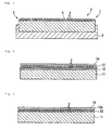
- Fig. 1 is a sectional view showing the CMP conditioner according to an embodiment of the invention.
- the CMP conditioner of this example has a disc shaped conditioner body 1: One of the surfaces is a conditioning surface 2, that faces and contacts the CMP conditioner's polishing pad: This conditioning surface 2, has abrasive grains 3 distributed, then fixed with binding phase 4; thus forming adhesive layer 5.
- the circumferential surface of conditioner body 1, and the opposite side of the conditioning surface 2, are attached to resin chassis 6; the chassis 6 has a contour that fits the dimensions of the conditioner.
- the abrasive grains 3 are diamond super-abrasive grains that have about the same average diameter, which are arranged approximately in a regular grid on the conditioning surface 2.
- the abrasive grains 3 protrude from the binding phase 4 surface by pressure adjustment during fabrication.
- the binding phase 4 is made of low temperature co-fired ceramics; this embodiment uses MgO-SiO 2 ceramics and the conditioner body 1 is also made of MgO-SiO 2 or SiC ceramics.
- this CMP conditioner On one circular side of a disc-shaped base of pre-sintered ceramics, the abrasive grains 3 are distributed and arranged, then they are sintered at temperatures lower than 1000°C.
- this sintering is preformed using spark plasma sintering; in which a raw object is placed in a mold structured by carbon dies and punches; this is placed under pressure and sintered using spark plasma generated by applying direct pulse currents to that raw object.
- Fig. 2 shows the abovementioned raw object as an example of conditioner material, during fabrication of the CMP conditioner in this embodiment.
- a pre-sintered ceramic base 11 made of MgO-SiO 2 or SiC one surface of this will become the conditioning surface 2; on this surface, a layer of low temperature co-fired sheet ceramics material 12 made of abovementioned materials, in the form of a sheet or foil with the thickness of 1 mm or less is placed: On that, abrasive grains 3 such as diamond super-abrasive grains, etc., are adhered using paste 13: On top of that alumina powder, SiC powder, or a sheet made of the granulation of these powders; these are placed as release agent 14.
- an abovementioned low temperature co-fired sheet ceramics material 12 is cut to fit the dimensions of the ceramics base 11; this sheet has abovementioned liquid paste 13 sprayed on it; on the sprayed surface, mesh having the grid size of the average grain size of abrasive grains 3 is placed; then the abrasive grains 3 are distributed on the mesh: The abrasive grains 3 that pass though the mesh are adhered by paste 13; the surplus grains 3 are removed by wiping, then the mesh is removed.
- the fixed abrasive grains 3 form a uniform grid pattern that matches the mesh: Then the low temperature co-fired sheet ceramics material 12 with the abrasive grains 3 fixed on it, is placed on the surface of the ceramic base 11; a coat of the abovementioned release agent 14 is placed on it, thus forming the conditioner material shown in Fig. 2 .
- the obtained conditioner material is set in the abovementioned mold, then placed in the spark plasma sintering system that will perform the spark plasma sintering: As the spark plasma sintering is performed under pressure, the abrasive grains 3 sink into the low temperature co-fired ceramics material 12, then the low temperature co-fired ceramics material 12 with the abrasive grains 3 fixed, becomes integrated with ceramic base 11; thus the abovementioned CMP conditioner body 1 will have, on it's conditioning surface 2; a firmly fixed single layer of abrasive grains 3, this becomes the abrasive grain layer 5: The fabrication of the CMP conditioner of the embodiment is completed when the chassis 6, is attached to the CMP conditioner body 1.
- the abrasive grain layer 5 has abrasive grains 3 fixed with binding phase 4; this binding phase 4 is formed when the low temperature co-fired ceramics material 12 is sintered, at the sintering temperature of 1000 °C or lower.
- the diameter of the conditioning surface 2 is 30 mm
- the abrasive grains 3 are diamond super-abrasive grains with the average grain size of 280 ⁇ m
- the abovementioned low temperature co-fired sheet ceramics material 12 is made of MgO-SiO 2 ceramics, at the thickness is about 0.4 mm:
- spark plasma sintering the abovementioned material is pressured at 20 KN for 1 minute at room temperature, then the temperature is increased to 650 °C in 5 minutes, next, the temperature is increased to 750 °C in 1 minute, the temperature is further increased to 800 °C for 1 minute, maintained at 800 °C for 1 minute, decreased to 300 °C in 10 minutes, then removed from the mold and cooled at room temperature, thus obtaining the abovementioned conditioner body 1.
- the conditioner surface 2 diameter is 98 mm: To sinter this by spark plasma sintering, the material is pressured at 20 KN for 1 minute at room temperature, then the temperature is increased 150 °C in 4 minutes, next, the temperature is increased to 700 °C in 5 minutes, temperature increased to 800 °C in 2 minutes, temperature increased to 850 °C in 2 minutes, the temperature is maintained at 850 °C for 1 minute, then the temperature is decreased to 300 °C in 100 minutes, then removed from the mold and cooled at room temperature.
- the conditioner body 1 is made of ceramics including the abrasive grain layer 5 and the binding phase 4; thus, there is very little such dissolution, 1 ppm or less, or no dissolution at all: If strong alkaline or strong acid slurry is used in the CMP conditioner, the conditioner body 1 will not corrode or the abrasive grains 3 is not dissociated.
- the conditioner body 1, made of ceramics, is mounted onto chassis 6, made of resin: attachments to join it to the CMP apparatus, such as screw holes can be made on chassis 6; there is no need to machine the conditioner body 1.
- the abovementioned binding phase 4 is made of low temperature co-fired ceramics material 12 such as MgO-SiO 2 ceramics; the sintering temperature is 1000 °C or lower; thus, if the abrasive grains 3 are diamond super-abrasive grains, they do not become blackened or carbonized and there is no need to coat the surface of the abrasive grains 3: The chipping that occurs in the abrasive grains 3 and the poor cutting performance by coating, leading to decrease the polishing rate of pad, are prevented.
- low temperature co-fired ceramics material 12 such as MgO-SiO 2 ceramics
- the abovementioned fabrication method uses, as conditioner material 12, low temperature co-fired ceramics material mentioned in the embodiment; this is sintered by spark plasma sintering:
- This spark plasma sintering makes it possible to increase the temperature of the raw object in a relatively short period of time; it is also possible to sinter at lower temperatures, thus reliably preventing damage to abrasive grains 3.
- the binding phase 4 sintered by spark plasma sintering has lesser pores and a denser structure; the Al 2 O 3 particles as a filler have sufficiently melted, hence almost none of Al 2 O 3 remains as spherical shape, thus making it possible to reliability retain abrasive grains 3.
- a low temperature co-fired sheet ceramics material 12 is placed on the surface of the abovementioned pre-sintered ceramic base 11, on that, abrasive grains 3, such as diamond super-abrasive grains are arrayed regularly by a mesh, and adhered by paste 13.
- abrasive grains 3 such as diamond super-abrasive grains are arrayed regularly by a mesh, and adhered by paste 13.
- Another example of preferable structure is shown in Fig.
- a pre-sintered ceramic base 11 has a low temperature co-fired sheet ceramics material 12 cut to fit the dimensions of the surface of the ceramic base 11; numerous holes 12a in a grid pattern are opened in the sheet, the hole size being approximately the same or somewhat smaller than the average diameter of the abrasive grains 3: Abrasive grains 3, in this case diamond super-abrasive grains are distributed on the holes 12a, the surplus abrasive grains 3 that did not fit in the holes 12a are removed; then low temperature co-fired ceramics material 12 with the abrasive grains 3 are placed on the surface of base 11, on that, an alumina sheet is placed as released agent 14.
- the abovementioned materials are sintered, preferably by spark plasma sintering, to construct a CMP conditioner. Since the structure of this CMP conditioner is the same as the conditioner of the embodiment, the efficiency is the same. Furthermore, the same sintering conditions are applied to the embodiment and the abovementioned materials.
- conditioner body 1 with an integrated abrasive grain layer 5 is formed by: A pre-sintered ceramic base 11 has low temperature co-fired ceramics material 12 placed on it, then it is sintered at low temperatures.
- Fig. 4 shows other examples of conditioner material: A mold, preferably from a spark plasma sintering system, has, as release agent, ceramics coat agent placed in it, then the ceramic material 15 in powder form is spread on the release agent 16.
- a low temperature co-fired sheet ceramics material 12 with the abrasive grains 3 are the same material as placed on the surface of ceramic base 11:
- the same low temperature co-fired sheet ceramics material 12 has holes 12a opened in it to attach the abrasive grains 3, then, an alumina sheet is placed on top as release agent 14: Then low temperature sintering is performed on both cases.
- both ceramic material 15 and low temperature co-fired ceramics material 12 used here are the same materials:
- the whole conditioner body 1, including the binding phase 4 and abrasive grain layer 5 can be efficiently sintered together at low temperature: If low temperature co-fired ceramics material 12 and material 15 with the binding phase 4 are sintered together, the CMP conditioner has an abrasive grain layer 5 with a higher ability to retain the abrasive grains 3. This advantage is especially evident when both low temperature co-fired ceramics material 12 and material 15 are the same low temperature co-fired ceramics material, such as MgO-SiO 2 ceramics.
- the conditioner body 1 is integrally molded by low temperature co-fired ceramics materials 15 placed in a mold, then sintered.
- the mold has release agent 16 put in; on that, material 15 is spread, then the diamond super-abrasive grains 3 are directly arrayed regularly; on that an alumina sheet is placed as release agent 14, and then, sintered at low temperatures.
- abrasive grains 3 are fixed in binding phase 4; forming abrasive layer 5, thus the whole of conditioner body 1 is formed by the integrated sintering of low temperature co-fired ceramics: thus the ability to retain the abrasive grains 3 increases.
- conditioner material shown in Fig. 4 and Fig. 5
- the powder form material 15 is spread in a mold, then sintered together at low temperatures with binding phase 4.
- the abrasive grains 3 and low temperature co-fired ceramics material 12 are the same as the abovementioned example; and if the material 15 in powder form and the low temperature co-fired ceramics material 12 are of the same composition:
- the material is pressured to 20 KN at room temperature for 1 minute, then the temperature is increased to 650°C in 5 minutes, the temperature is increased to 750°C in 1 minute, the temperature is increased to 800°C in 1 minute.
- the next step differs from the abovementioned case in that the whole conditioner body 1 including material 15 is sintered; thus it is maintained at 800°C for 5 minutes. Afterwards is the same as the abovementioned example, the temperature is decreased to 300°C in 10 minutes, taken out of the mold and cooled at room temperature.
Landscapes
- Engineering & Computer Science (AREA)
- Mechanical Engineering (AREA)
- Grinding-Machine Dressing And Accessory Apparatuses (AREA)
- Mechanical Treatment Of Semiconductor (AREA)
- Polishing Bodies And Polishing Tools (AREA)
Abstract
To provide a CMP conditioner that prevents dissolution of metals in slurry, without the chipping of the abrasive grains and/or decreasing the cutting performance.
[Issues to be solved by the invention]
The CMP apparatus has a polishing pad that faces and contacts conditioning surface 2 of the conditioner body 1. On this conditioning surface 2, abrasive grains 3 are distributed and fixed to form abrasive grain layer 5, thus forming the CMP conditioner. The conditioner body 1 is made of ceramics, the abrasive grains 3 in the abrasive grain layer 5 are held by binding phase 4 made of low temperature co-fired ceramics.
Description
- The present invention relates to a CMP conditioner for conditioning the polishing pad of a CMP (Chemical Mechanical Polishing) apparatus that polishes semiconductor wafers and the like.
- Various kinds of CMP conditioners in which abrasive grains are fixed by metal plating binding phase of Ni and the like, on a base metal plate, such as stainless steel have been reported. When highly corrosive strong acid or strong alkaline slurry is used in a CMP apparatus, the binding phase metal is dissolved, it become undesirable to polish semiconductor wafers in such slurry with dissolved metals. To avoid this problem, for example,
patent documents 1 and 2 disclose a CMP conditioner in which ceramics is employed as the binding phase.
[Patent Document 1]Japanese Patent No. 527448
[Patent Document 2]Japanese Patent application Publication No. 2005-288685 - In the CMP conditioner disclosed in
Patent Documents 1 and 2, the ceramics binding phase is sintered for adhesion of abrasive grains at the high temperature of 1200°C. At such a high temperature, for example, if the abrasive grains are diamond super-abrasive grains, surfaces of the super-abrasive grains became carbonized and blackened by the heat and chipping tends to occur. On the other hand, to prevent the surfaces from such carbonation by the heat, if the surfaces of the diamond super-abrasive grains are coated as disclosed inPatent Documents 1 and 2, the cutting performance of the polishing pad by such super-abrasive grains became poor, which results in decrease of the pad polishing rate. - With such background, this invention aims to provide a CMP conditioner which restricts metal dissolution in the slurry, without causing the chipping of the abrasive grains and/or decreasing the cutting performance.
- To overcome the above problems and accomplish the above objective, this invention features a CMP conditioner comprised of a conditioner body, facing and in contact with the polishing pad of the CMP apparatus; the CMP conditioner having an abrasive grain layer formed on the conditioning surface of the conditioning body; the abrasive grains distributed and fixed on the abrasive grain layer: The above mentioned conditioner body is made of ceramics, and the binding phase holding and fixing the abrasive grains in the abrasive grain layer is made of low temperature co-fired ceramics (LTCC).
- The abrasive grains in the CMP conditioner are held in the binding phase, which is made of low temperature co-fired ceramics; these low temperature co-fired ceramics are known to compose semiconductor substrates that can be sintered at relatively low temperatures of 1000°C or below. Therefore even the diamond super-abrasive grains need no surface coating, as the carbonization and/or chipping by the sintering is prevented. In addition, the abrasive grain layer holding the abrasive grains is formed on the binding phase; this layer and the conditioning surface of the conditioner body are made of the same ceramics: Thus the CMP conditioner with the above structure can highly restrict metal dissolution in strong acid or strong alkaline slurry.
- Although it is possible to use pre-sintered ceramics for the ceramics composing the conditioner body, if the body is made of the low temperature co-fired ceramics, and the binding phase uses the same low temperature co-fired ceramics, the conditioner body can be sintered integrally with the binding phase. An example of the low temperature co-fired ceramics that can be used to compose the binding phase and/or the conditioner body is MgO-SiO2 ceramics. Preferably, spark plasma sintering (SPS) should be used for sintering. Since it is difficult to make holes for screws in the ceramics conditioner body to attach the CMP conditioner to the CMP apparatus, it is preferable that sections of the conditioner body are supported by a chassis made of resin, except for the conditioning surface.
- The CMP conditioner of this invention can prevent metal dissolution in slurry without causing the chipping of the abrasive grains and/or decreasing the cutting performance. Thus, it is possible to prevent, with reliability, semiconductor wafers from becoming contaminated by dissolved metals, and/or defects due to scratches, etc., from the abrasive grains in the CMP apparatus; thereby the polishing pad is in reliable condition, allowing efficient polishing of the semiconductor wafers.
-
-
Fig. 1 is a sectional view showing the CMP conditioner according to an embodiment of the invention. -
Fig. 2 is a sectional view showing an example of conditioner material sintered at low temperature during the fabrication of the CMP conditioner shown inFig. 1 . -
Fig. 3 is a sectional view showing another example of conditioner material sintered at low temperature during the fabrication of the CMP conditioner shown inFig. 1 . -
Fig. 4 is a sectional view showing still another example of conditioner material sintered at low temperature during the fabrication of the CMP conditioner shown inFig. 1 . -
Fig. 5 is a sectional view showing yet another example of conditioner material sintered at low temperature during the fabrication of the CMP conditioner shown inFig. 1 . -
- 1:
- Conditioner body
- 2:
- Conditioning surface
- 3:
- Abrasive grains
- 4:
- Binding phase
- 5:
- Abrasive grain layer
- 6:
- Chassis
- 11:
- Ceramic base
- 12:
- Low temperature co-fired sheet ceramics
- 13:
- Paste
- 15:
- Ceramic materials
- 14, 16:
- Release agent
-
Fig. 1 is a sectional view showing the CMP conditioner according to an embodiment of the invention. The CMP conditioner of this example has a disc shaped conditioner body 1: One of the surfaces is aconditioning surface 2, that faces and contacts the CMP conditioner's polishing pad: Thisconditioning surface 2, hasabrasive grains 3 distributed, then fixed with bindingphase 4; thus formingadhesive layer 5. The circumferential surface of conditioner body 1, and the opposite side of theconditioning surface 2, are attached toresin chassis 6; thechassis 6 has a contour that fits the dimensions of the conditioner. - In this embodiment, the
abrasive grains 3 are diamond super-abrasive grains that have about the same average diameter, which are arranged approximately in a regular grid on theconditioning surface 2. Theabrasive grains 3 protrude from the bindingphase 4 surface by pressure adjustment during fabrication. - The binding
phase 4 is made of low temperature co-fired ceramics; this embodiment uses MgO-SiO2 ceramics and the conditioner body 1 is also made of MgO-SiO2 or SiC ceramics. - To fabricate this CMP conditioner: On one circular side of a disc-shaped base of pre-sintered ceramics, the
abrasive grains 3 are distributed and arranged, then they are sintered at temperatures lower than 1000°C. Preferably, this sintering is preformed using spark plasma sintering; in which a raw object is placed in a mold structured by carbon dies and punches; this is placed under pressure and sintered using spark plasma generated by applying direct pulse currents to that raw object. -
Fig. 2 shows the abovementioned raw object as an example of conditioner material, during fabrication of the CMP conditioner in this embodiment. In this example, a pre-sinteredceramic base 11 made of MgO-SiO2 or SiC, one surface of this will become theconditioning surface 2; on this surface, a layer of low temperature co-firedsheet ceramics material 12 made of abovementioned materials, in the form of a sheet or foil with the thickness of 1 mm or less is placed: On that,abrasive grains 3 such as diamond super-abrasive grains, etc., are adhered using paste 13: On top of that alumina powder, SiC powder, or a sheet made of the granulation of these powders; these are placed asrelease agent 14. - To prepare such conditioner material: for example, an abovementioned low temperature co-fired
sheet ceramics material 12 is cut to fit the dimensions of theceramics base 11; this sheet has abovementionedliquid paste 13 sprayed on it; on the sprayed surface, mesh having the grid size of the average grain size ofabrasive grains 3 is placed; then theabrasive grains 3 are distributed on the mesh: Theabrasive grains 3 that pass though the mesh are adhered bypaste 13; thesurplus grains 3 are removed by wiping, then the mesh is removed. Thus the fixedabrasive grains 3 form a uniform grid pattern that matches the mesh: Then the low temperature co-firedsheet ceramics material 12 with theabrasive grains 3 fixed on it, is placed on the surface of theceramic base 11; a coat of theabovementioned release agent 14 is placed on it, thus forming the conditioner material shown inFig. 2 . - The obtained conditioner material is set in the abovementioned mold, then placed in the spark plasma sintering system that will perform the spark plasma sintering: As the spark plasma sintering is performed under pressure, the
abrasive grains 3 sink into the low temperatureco-fired ceramics material 12, then the low temperatureco-fired ceramics material 12 with theabrasive grains 3 fixed, becomes integrated withceramic base 11; thus the abovementioned CMP conditioner body 1 will have, on it'sconditioning surface 2; a firmly fixed single layer ofabrasive grains 3, this becomes the abrasive grain layer 5: The fabrication of the CMP conditioner of the embodiment is completed when thechassis 6, is attached to the CMP conditioner body 1. - In CMP conditioners with such structure, the
abrasive grain layer 5 hasabrasive grains 3 fixed withbinding phase 4; thisbinding phase 4 is formed when the low temperatureco-fired ceramics material 12 is sintered, at the sintering temperature of 1000 °C or lower. For example, in this embodiment, the diameter of theconditioning surface 2 is 30 mm, theabrasive grains 3 are diamond super-abrasive grains with the average grain size of 280 µm, the abovementioned low temperature co-firedsheet ceramics material 12 is made of MgO-SiO2 ceramics, at the thickness is about 0.4 mm: To sinter this by spark plasma sintering, the abovementioned material is pressured at 20 KN for 1 minute at room temperature, then the temperature is increased to 650 °C in 5 minutes, next, the temperature is increased to 750 °C in 1 minute, the temperature is further increased to 800 °C for 1 minute, maintained at 800 °C for 1 minute, decreased to 300 °C in 10 minutes, then removed from the mold and cooled at room temperature, thus obtaining the abovementioned conditioner body 1. - If the
abrasive grains 3 and low temperatureco-fired ceramics material 12 is the same as above, and theconditioner surface 2 diameter is 98 mm: To sinter this by spark plasma sintering, the material is pressured at 20 KN for 1 minute at room temperature, then the temperature is increased 150 °C in 4 minutes, next, the temperature is increased to 700 °C in 5 minutes, temperature increased to 800 °C in 2 minutes, temperature increased to 850 °C in 2 minutes, the temperature is maintained at 850 °C for 1 minute, then the temperature is decreased to 300 °C in 100 minutes, then removed from the mold and cooled at room temperature. - Dissolution of one or several metals such as Fe, Co, Ni, Cu, and Zn occurs in CMP conditioners using metal plating phase as the binding phase: In CMP conditioners in this embodiment, fabricated and structured as previously mentioned, the conditioner body 1 is made of ceramics including the
abrasive grain layer 5 and thebinding phase 4; thus, there is very little such dissolution, 1 ppm or less, or no dissolution at all: If strong alkaline or strong acid slurry is used in the CMP conditioner, the conditioner body 1 will not corrode or theabrasive grains 3 is not dissociated. The conditioner body 1, made of ceramics, is mounted ontochassis 6, made of resin: attachments to join it to the CMP apparatus, such as screw holes can be made onchassis 6; there is no need to machine the conditioner body 1. - In our abovementioned CMP conditioner, the abovementioned
binding phase 4 is made of low temperatureco-fired ceramics material 12 such as MgO-SiO2 ceramics; the sintering temperature is 1000 °C or lower; thus, if theabrasive grains 3 are diamond super-abrasive grains, they do not become blackened or carbonized and there is no need to coat the surface of the abrasive grains 3: The chipping that occurs in theabrasive grains 3 and the poor cutting performance by coating, leading to decrease the polishing rate of pad, are prevented. In our CMP conditioner with the abovementioned structure, the wafer contamination due to dissolved metals or the scratches on the wafers from the chipping of abrasive grains can be prevented, while the polishing pad is in reliable condition, thus making possible efficient polishing of semiconductor wafers. - To fabricate such CMP conditioners, the abovementioned fabrication method uses, as
conditioner material 12, low temperature co-fired ceramics material mentioned in the embodiment; this is sintered by spark plasma sintering: This spark plasma sintering makes it possible to increase the temperature of the raw object in a relatively short period of time; it is also possible to sinter at lower temperatures, thus reliably preventing damage toabrasive grains 3. Compared to sintering performed in a conventional electric oven, thebinding phase 4 sintered by spark plasma sintering has lesser pores and a denser structure; the Al2O3 particles as a filler have sufficiently melted, hence almost none of Al2O3 remains as spherical shape, thus making it possible to reliability retainabrasive grains 3. - An example of the above mentioned conditioner materials used to fabricate the conditioning body 1 of such CMP conditioners: A low temperature co-fired
sheet ceramics material 12 is placed on the surface of the abovementioned pre-sinteredceramic base 11, on that,abrasive grains 3, such as diamond super-abrasive grains are arrayed regularly by a mesh, and adhered bypaste 13. Another example of preferable structure is shown inFig. 3 : A pre-sinteredceramic base 11 has a low temperature co-firedsheet ceramics material 12 cut to fit the dimensions of the surface of theceramic base 11;numerous holes 12a in a grid pattern are opened in the sheet, the hole size being approximately the same or somewhat smaller than the average diameter of the abrasive grains 3:Abrasive grains 3, in this case diamond super-abrasive grains are distributed on theholes 12a, the surplusabrasive grains 3 that did not fit in theholes 12a are removed; then low temperatureco-fired ceramics material 12 with theabrasive grains 3 are placed on the surface ofbase 11, on that, an alumina sheet is placed as releasedagent 14. - The abovementioned materials are sintered, preferably by spark plasma sintering, to construct a CMP conditioner. Since the structure of this CMP conditioner is the same as the conditioner of the embodiment, the efficiency is the same. Furthermore, the same sintering conditions are applied to the embodiment and the abovementioned materials.
- As shown in these examples, conditioner body 1 with an integrated
abrasive grain layer 5 is formed by: A pre-sinteredceramic base 11 has low temperatureco-fired ceramics material 12 placed on it, then it is sintered at low temperatures.Fig. 4 shows other examples of conditioner material: A mold, preferably from a spark plasma sintering system, has, as release agent, ceramics coat agent placed in it, then theceramic material 15 in powder form is spread on therelease agent 16. Placed on top of theceramic material 15 is, in one abovementioned example, a low temperature co-firedsheet ceramics material 12 with theabrasive grains 3; these are the same material as placed on the surface of ceramic base 11: In another abovementioned example, the same low temperature co-firedsheet ceramics material 12, hasholes 12a opened in it to attach theabrasive grains 3, then, an alumina sheet is placed on top as release agent 14: Then low temperature sintering is performed on both cases. - When low temperature
co-fired ceramics material 12 is placed onceramic material 15 and sintered at low temperatures, it is preferable that bothceramic material 15 and low temperatureco-fired ceramics material 12 used here are the same materials: Thus the whole conditioner body 1, including thebinding phase 4 andabrasive grain layer 5, can be efficiently sintered together at low temperature: If low temperatureco-fired ceramics material 12 andmaterial 15 with thebinding phase 4 are sintered together, the CMP conditioner has anabrasive grain layer 5 with a higher ability to retain theabrasive grains 3. This advantage is especially evident when both low temperatureco-fired ceramics material 12 andmaterial 15 are the same low temperature co-fired ceramics material, such as MgO-SiO2 ceramics. - In these before-mentioned other examples, the conditioner body 1 is integrally molded by low temperature
co-fired ceramics materials 15 placed in a mold, then sintered. In yet another example, shown inFig. 5 : As the material of the raw object, the mold hasrelease agent 16 put in; on that,material 15 is spread, then the diamondsuper-abrasive grains 3 are directly arrayed regularly; on that an alumina sheet is placed asrelease agent 14, and then, sintered at low temperatures. In this case,abrasive grains 3 are fixed inbinding phase 4; formingabrasive layer 5, thus the whole of conditioner body 1 is formed by the integrated sintering of low temperature co-fired ceramics: thus the ability to retain theabrasive grains 3 increases. - In conditioner material (s) shown in
Fig. 4 and Fig. 5 , thepowder form material 15 is spread in a mold, then sintered together at low temperatures withbinding phase 4. If theabrasive grains 3 and low temperatureco-fired ceramics material 12 are the same as the abovementioned example; and if the material 15 in powder form and the low temperatureco-fired ceramics material 12 are of the same composition: To sinter a conditioner body 1 having aconditioning surface 2 with a diameter of 30 mm by using the spark sintering plasma: The material is pressured to 20 KN at room temperature for 1 minute, then the temperature is increased to 650°C in 5 minutes, the temperature is increased to 750°C in 1 minute, the temperature is increased to 800°C in 1 minute. These steps are the same as the abovementioned example; the next step differs from the abovementioned case in that the whole conditioner body 1 includingmaterial 15 is sintered; thus it is maintained at 800°C for 5 minutes. Afterwards is the same as the abovementioned example, the temperature is decreased to 300°C in 10 minutes, taken out of the mold and cooled at room temperature.
Claims (4)
- A CMP conditioner comprising a conditioner body that faces and contacts the polishing pad of a CMP apparatus, and an abrasive grain layer formed on a conditioning surface of the conditioning body, abrasive grains being distributed and adhered on the abrasive grain layer, the CMP conditioner being characterized in that the conditioner body is made of ceramics and a binding phase holding the abrasive grains in the abrasive grain layer is made of low temperature co-fired ceramics.
- The CMP conditioner according to Claim 1, wherein the conditioner body is made of low temperature co-fired ceramics.
- The CMP conditioner according to Claim 1 or Claim 2, wherein the low temperature co-fired ceramics is MgO-SiO2 ceramics.
- The CMP conditioner according to any one of Claims 1 to 3, wherein sections other than the conditioning surface of the conditioner body are supported by a chassis made of resin.
Applications Claiming Priority (1)
| Application Number | Priority Date | Filing Date | Title |
|---|---|---|---|
| JP2006321542A JP2008132573A (en) | 2006-11-29 | 2006-11-29 | CMP conditioner |
Publications (1)
| Publication Number | Publication Date |
|---|---|
| EP1927434A1 true EP1927434A1 (en) | 2008-06-04 |
Family
ID=39046715
Family Applications (1)
| Application Number | Title | Priority Date | Filing Date |
|---|---|---|---|
| EP07023031A Withdrawn EP1927434A1 (en) | 2006-11-29 | 2007-11-28 | CMP conditioner |
Country Status (5)
| Country | Link |
|---|---|
| US (1) | US20080132153A1 (en) |
| EP (1) | EP1927434A1 (en) |
| JP (1) | JP2008132573A (en) |
| KR (1) | KR20080048947A (en) |
| TW (1) | TW200823011A (en) |
Families Citing this family (9)
| Publication number | Priority date | Publication date | Assignee | Title |
|---|---|---|---|---|
| SG174351A1 (en) | 2009-03-24 | 2011-10-28 | Saint Gobain Abrasives Inc | Abrasive tool for use as a chemical mechanical planarization pad conditioner |
| EP2438609A4 (en) * | 2009-06-02 | 2016-03-09 | Saint Gobain Abrasives Inc | CORROSION RESISTANT CMP PACKAGING TOOLS AND METHODS OF MAKING AND USING THE SAME |
| US20110097977A1 (en) * | 2009-08-07 | 2011-04-28 | Abrasive Technology, Inc. | Multiple-sided cmp pad conditioning disk |
| EP2474025A2 (en) | 2009-09-01 | 2012-07-11 | Saint-Gobain Abrasives, Inc. | Chemical mechanical polishing conditioner |
| DE102011109553B4 (en) * | 2011-08-05 | 2013-04-11 | Micro-Epsilon Messtechnik Gmbh & Co. Kg | Sensor and sensor element |
| CN203390712U (en) * | 2013-04-08 | 2014-01-15 | 宋健民 | Chemical mechanical polishing dresser |
| TWI706831B (en) * | 2020-02-10 | 2020-10-11 | 富仕多科技有限公司 | Base seat used in polishing pad conditioning apparatus |
| CN112959236A (en) * | 2021-02-24 | 2021-06-15 | 合肥铨得合半导体有限责任公司 | Ceramic powder of diamond disk and diamond anti-oxidation sintering method |
| TWI780883B (en) * | 2021-08-31 | 2022-10-11 | 中國砂輪企業股份有限公司 | Chemical mechanical polishing pad conditioner and manufacture method thereof |
Citations (3)
| Publication number | Priority date | Publication date | Assignee | Title |
|---|---|---|---|---|
| EP0499865A1 (en) * | 1991-02-04 | 1992-08-26 | Sumitomo Electric Industries, Ltd. | Glass-aluminum nitride composite material |
| JP2000190200A (en) * | 1998-12-25 | 2000-07-11 | Mitsubishi Materials Silicon Corp | Seasoning jig for polishing cloth |
| US6755720B1 (en) * | 1999-07-15 | 2004-06-29 | Noritake Co., Limited | Vitrified bond tool and method of manufacturing the same |
Family Cites Families (4)
| Publication number | Priority date | Publication date | Assignee | Title |
|---|---|---|---|---|
| US5380390B1 (en) * | 1991-06-10 | 1996-10-01 | Ultimate Abras Systems Inc | Patterned abrasive material and method |
| US6123612A (en) * | 1998-04-15 | 2000-09-26 | 3M Innovative Properties Company | Corrosion resistant abrasive article and method of making |
| JP3527448B2 (en) * | 1999-12-20 | 2004-05-17 | 株式会社リード | Dresser for CMP polishing cloth and its manufacturing method |
| TWI286963B (en) * | 2004-03-10 | 2007-09-21 | Read Co Ltd | Dresser for polishing cloth and method for manufacturing thereof |
-
2006
- 2006-11-29 JP JP2006321542A patent/JP2008132573A/en not_active Withdrawn
-
2007
- 2007-10-29 TW TW096140528A patent/TW200823011A/en unknown
- 2007-11-28 EP EP07023031A patent/EP1927434A1/en not_active Withdrawn
- 2007-11-28 KR KR1020070121768A patent/KR20080048947A/en not_active Withdrawn
- 2007-11-28 US US11/946,135 patent/US20080132153A1/en not_active Abandoned
Patent Citations (4)
| Publication number | Priority date | Publication date | Assignee | Title |
|---|---|---|---|---|
| EP0499865A1 (en) * | 1991-02-04 | 1992-08-26 | Sumitomo Electric Industries, Ltd. | Glass-aluminum nitride composite material |
| JP2000190200A (en) * | 1998-12-25 | 2000-07-11 | Mitsubishi Materials Silicon Corp | Seasoning jig for polishing cloth |
| US6755720B1 (en) * | 1999-07-15 | 2004-06-29 | Noritake Co., Limited | Vitrified bond tool and method of manufacturing the same |
| US20040185763A1 (en) * | 1999-07-15 | 2004-09-23 | Noritake Co., Limited | Vitrified bond tool and method of manufacturing the same |
Also Published As
| Publication number | Publication date |
|---|---|
| TW200823011A (en) | 2008-06-01 |
| JP2008132573A (en) | 2008-06-12 |
| US20080132153A1 (en) | 2008-06-05 |
| KR20080048947A (en) | 2008-06-03 |
Similar Documents
| Publication | Publication Date | Title |
|---|---|---|
| US20080132153A1 (en) | Cmp conditioner | |
| KR101483314B1 (en) | Extended life abrasive article and method | |
| KR100360669B1 (en) | Abrasive dressing tool and manufac ture method of abrasive dressing tool | |
| US7467989B2 (en) | Ceramic polishing pad dresser and method for fabricating the same | |
| US7300338B2 (en) | CMP diamond conditioning disk | |
| JP5295868B2 (en) | Dresser for polishing cloth and method for producing the same | |
| JP3527448B2 (en) | Dresser for CMP polishing cloth and its manufacturing method | |
| KR20080077094A (en) | Aluminum-silicon carbide composite and heat dissipation parts using the same | |
| SK9552001A3 (en) | Superabrasive wheel with active bond | |
| TW201105439A (en) | Composite material substrate for LED luminescent element, method for manufacturing the same and LED luminescent element | |
| KR20090078647A (en) | Conditioner for CPM Pads | |
| EP3135783B1 (en) | Aluminum-diamond composite, and heat dissipating component using same | |
| US6579332B1 (en) | Metal-bonded grinding tool and manufacturing method therefor | |
| JPH0215977A (en) | Diamond grindstone and manufacture thereof | |
| EP1201367B1 (en) | Dresser for polishing cloth and manufacturing method therefor | |
| KR20020046471A (en) | Method for chemical mechanical polishing pad conditioner | |
| JP6263725B2 (en) | Suction table | |
| JP2005288685A (en) | Dresser for polishing cloth, and manufacturing method thereof | |
| JP2007229865A (en) | Polishing pad dresser | |
| JP7336864B2 (en) | cutting blade | |
| KR200201101Y1 (en) | Abrasive dressing tool | |
| JPH02224976A (en) | Inner periphery type metal bonded abrasive cutting wheel and using method and manufacture thereof | |
| JPH07186046A (en) | Use of metal bond abrasive cutting wheel of inner circumferential type | |
| JP2004119858A (en) | Semiconductor device lead bending fixture |
Legal Events
| Date | Code | Title | Description |
|---|---|---|---|
| PUAI | Public reference made under article 153(3) epc to a published international application that has entered the european phase |
Free format text: ORIGINAL CODE: 0009012 |
|
| AK | Designated contracting states |
Kind code of ref document: A1 Designated state(s): AT BE BG CH CY CZ DE DK EE ES FI FR GB GR HU IE IS IT LI LT LU LV MC MT NL PL PT RO SE SI SK TR |
|
| AX | Request for extension of the european patent |
Extension state: AL BA HR MK RS |
|
| STAA | Information on the status of an ep patent application or granted ep patent |
Free format text: STATUS: THE APPLICATION HAS BEEN WITHDRAWN |
|
| 18W | Application withdrawn |
Effective date: 20081205 |