EP1925905A1 - Signal processing method and unit for a dimension-gauging system - Google Patents
Signal processing method and unit for a dimension-gauging system Download PDFInfo
- Publication number
- EP1925905A1 EP1925905A1 EP06124619A EP06124619A EP1925905A1 EP 1925905 A1 EP1925905 A1 EP 1925905A1 EP 06124619 A EP06124619 A EP 06124619A EP 06124619 A EP06124619 A EP 06124619A EP 1925905 A1 EP1925905 A1 EP 1925905A1
- Authority
- EP
- European Patent Office
- Prior art keywords
- transfer function
- field
- excitation
- magnetic field
- measured
- Prior art date
- Legal status (The legal status is an assumption and is not a legal conclusion. Google has not performed a legal analysis and makes no representation as to the accuracy of the status listed.)
- Granted
Links
Images
Classifications
-
- G—PHYSICS
- G01—MEASURING; TESTING
- G01B—MEASURING LENGTH, THICKNESS OR SIMILAR LINEAR DIMENSIONS; MEASURING ANGLES; MEASURING AREAS; MEASURING IRREGULARITIES OF SURFACES OR CONTOURS
- G01B7/00—Measuring arrangements characterised by the use of electric or magnetic techniques
- G01B7/02—Measuring arrangements characterised by the use of electric or magnetic techniques for measuring length, width or thickness
- G01B7/06—Measuring arrangements characterised by the use of electric or magnetic techniques for measuring length, width or thickness for measuring thickness
Definitions
- the invention relates to a signal processing method to determine at least one dimension of a non-ferrous, electrically conducting object comprising the step of measuring the reaction of a magnetic field to a change in excitation, where the magnetic field is being applied to the object.
- the invention relates also to a signal processing unit for a dimension-gauging system.
- the EP0349528B1 suggests changing the excitation of the magnetic field considerably by switching the current supply off.
- the time elapsing between the switch-off and the decaying of the part of the magnetic field being present in the air gap between the measuring equipment and the object is measured.
- the geometrical dimensions of the object are then determined based on the length of the measured time.
- the decay of the magnetic field in the air gap is called primary decay.
- the method proposed in EP0349528B1 was further improved in WO 01/01065 A1 to achieve a higher accuracy for objects with smaller dimensions. There, the measurement is not started directly after the excitation was changed but only after the primary decay is completed. After the primary decay only the part of the magnetic field inside the object remains which decays with a bigger time delay than the field in the air gap. The decay of the magnetic field in the object can be called secondary decay. The length of the secondary decay depends again on the geometric and resistive parameters of the object. Further embodiments of this method are described in WO 2005/064268 A1 and WO 2005/064269 A1 .
- the known methods all have in common that a period of time is measured and used to determine the geometrical dimensions of the object.
- This approach has a main drawback which especially affects the measuring accuracy of objects with small dimensions, like thin sheets. Since only two measurements are used to define the period of time, the initiation of the sampling of these two measurements becomes crucial. Only minor variations in the time to sample caused for example by varying delays in the signal processing circuitry may lead to significant differences in the measurement result. These differences increase with decreased dimensions of the object. Furthermore, the exact determination of the point in time when the change in the excitation of the magnetic field takes effect becomes more important if the object is smaller.
- the object of the invention is achieved by the provision of a signal processing method according to claim 1 and a signal processing unit according to claim 12.
- the invention is based on the general idea of searching a solution in the frequency domain instead of the time domain, since a further increase of precision in timing the two measurements discussed above is less applicable due to the resulting considerable effort and expenses.
- the inventive signal processing unit comprises the respective means to perform the method steps.
- the advantage of the current invention is that the accuracy of the determined dimension is now independent of the specific timing of only a few measurements. Instead, multiple samples are taken, which means that the time-dependent reaction of the magnetic field is taken into account as a whole function. Accordingly, the number of samples should be at least twenty, but considerably higher numbers of samples are preferred. Since more data samples are processed, reliable results are yielded even for very thin sheets.
- equidistant samples of the time-dependent reaction of the magnetic field are taken, i.e. the sampling is carried out at a constant sampling frequency. This simplifies the subsequent signal processing.
- the measured field transfer function For determining the measured field transfer function it is suggested to use equidistant samples of the time-dependent excitation of the magnetic field and to derive the corresponding frequency transformation by known mathematical methods, or to use a specific signal form in the excitation which may be represented by a low-order transfer function. If the second possibility is applied, preferably a step function is used for the excitation.
- the predetermined field transfer function is determined as a combination of the transfer function of the excitation with the transfer function representing the transmission behaviour of the non-ferrous object for a magnetic field.
- the transfer function representing the transmission behaviour of the object can be derived by known methods of control theory, for example by formulating a dynamic model of the behaviour in form of a linear, time-invariant system and by transforming the model into the frequency domain using Laplace transform.
- the general form of the predetermined field transfer function is better adapted to the real dynamic behaviour of the system compared to a general form found be applying known black-box methods of system identification, where the term system describes the dynamic behaviour between the excitation of the magnetic field and the field reaction caused by the object.
- the field reaction has to be measured on that side of the object which lies opposite to the side of the excitation of the magnetic field.
- the predetermined field transfer function is determined as a combination of the transfer function of the excitation with the transfer function representing the reflection behaviour of the object for a magnetic field. Accordingly, the field reaction has then to be measured on the same side of the object where the magnetic field is generated.
- Both embodiments can also be combined by formulating a predetermined field transfer function which comprises the excitation as well as the transmission and the reflection behaviour of the object. The field reaction is then measured on both sides of the object.
- the predetermined field transfer function is even closer adapted to the real system behaviour by taking into account further parts of the system which may influence the system dynamics. It is suggested that a part of the field transfer function may represent the behaviour of a field-generating coil and/or the behaviour of a field-measuring coil and/or the behaviour of a data sampling unit.
- the proposed invention is further suggested to be made applicable to the measurement of more than just one dimension of the object.
- the system model to represent the dynamic behaviour between the excitation and the field reaction, and hence the predetermined field transfer function can be extended to include the influence of a second and a third dimension of the object or to include material parameters of the object, such as conductivity or resistivity, respectively.
- material parameters of the object such as conductivity or resistivity, respectively.
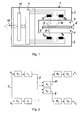
- the thickness-gauging system 1 of Fig. 1 has a U-shape form. It comprises two coils inside each of the legs of the U-shape; an upper transmitting coil T A and an upper receiving coil R A inside the upper leg 2 and a lower transmitting coil T B and a lower receiving coil R B inside the lower leg 3.
- a control unit 4 is connected to the two transmitting coils T A and T B in order to control their excitation by applying a corresponding current to them.
- a magnetic field develops in the open space between the two legs 2 and 3. This magnetic field penetrates into a thin sheet 5 which is placed inside the open space between the two legs 2 and 3 and which divides the open space into an upper space 6 and a lower space 7.
- the sheet 5 is made of a non-ferrous, electrically conductive material, such as a non-ferrous metal like aluminium or copper or such as an electrically conductive polymer or rubber, where the material has the resistivity ⁇ .
- the sheet 5 has the thickness d.
- the magnetic field generated by one or both of the transmitting coils T A and T B induces a current inside the sheet 5 which in turn induces a voltage in the receiving coils R A and R B .
- the induced voltage is measured by the control unit 4.
- the transmitting coils T A and T B and the sheet 5 are placed in such a way to each other that of the three geometric dimensions of the sheet only the thickness d influences the voltages induced in the receiving coils R A and R B .
- This arrangement is described in further detail in WO 01/01065A1 . Accordingly, the voltages induced in the receiving coils R A and R B represent the reaction of the magnetic field, where this reaction depends on the excitation of the field and on the thickness d and the resistivity ⁇ of sheet 5.
- Fig. 1 it is schematically shown that only the upper transmitting coil T A is excited.
- a magnetic field 8 develops inside the upper space 6, which penetrates the sheet 5. While transmitting through the sheet 5 the dynamic behaviour and the amplitude of the magnetic field 8 are changed. Part of the changed magnetic field leaves the sheet 5 on the opposite side of where it penetrated into the sheet. This part of the magnetic field is called transmitted field 9.
- the transmitted field 9 enters the lower open space 7 and reaches the lower receiving coil R B , where it can be detected.
- Another part of the changed magnetic field leaves the sheet 5 on the same side of where it penetrated into the sheet. This part is called the reflected field 10 and it extends into the upper open space 6 where it is detected by the upper receiving coil R A .
- the signal processing unit 11 receives from the control unit 4 data representing the time-dependent behaviour of the excitation of the magnetic field and of the reaction of the magnetic field, i.e. the induced voltages. From these data and from predetermined and stored information, the signal processing unit 11 determines the thickness d and the resistivity ⁇ of the sheet 5 by a method described below. Instead of being arranged as a separate hardware unit as depicted in Fig. 1, the signal processing unit 11 may also be integrated directly in the control unit 4.
- the signal processing unit 11 is connected to external devices via an interface 12 in order to output the thickness d and the resistivity ⁇ to a display and/or an external storage unit and/or a central control unit.
- the general form of the field transfer function In order to determine the thickness d and resistivity ⁇ from the measured time-dependent behaviours of the excitation and of the field reaction in the frequency domain, the general form of the field transfer function needs to be predetermined, so that the expected number of parameters and their influence on the transfer function are known.
- the general form of the transfer function is determined from a combination of separate transfer functions, each representing the dynamic behaviour of one of the elements influencing the overall dynamics between excitation and measurement of the field reaction.
- known methods of system identification may be used.
- the overall dynamic system represented by the predetermined field transfer function and the interconnection of its separate parts are shown in the block diagram in Fig. 2.
- the excitation constitutes the input variable X of the system. Depending on which of the transmitting coils is excited, the input variable may either be specified as X A or X B .
- the situation in Fig. 2 corresponds to the situation shown in Fig. 1 where only the upper transmitting coil X A is excited.
- the dynamic behaviour of the control signal generated by the control unit 4 to initiate or change the excitation of the transmitting coil T A is represented by the transfer function E A .
- the similar transfer functions, E B and T B are derived for the lower side.
- the generated or changed magnetic field 8 is transformed by the sheet 5 into two main parts, the transmitted field 9 and the reflected field 10.
- the process of voltage induction in the receiving coils R A and R B is represented by the corresponding transfer functions R A and R B
- the process of data sampling during the measurement of the time-dependent behaviour of the induced voltages is described by the respective transfer functions D A and D B .
- a transfer function F AR can be derived representing the behaviour between the excitation X A of the upper transmitting coil T A and the measurement of the field reaction Y AA at the upper receiving coil R A :
- F BR and F BT can be derived as:
- G(s) is the general form of the predetermined field transfer function used in the method described below to determine the thickness d and the resistivity ⁇ of the sheet 5.
- the parameters of the predetermined field transfer function G(s) are the gain b and the time constant a. Both parameters change with changing thickness d and resistivity ⁇ of the sheet 5, so that G(s) can also be written as G(d, ⁇ )
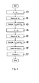
- the method to determine the thickness d and the resistivity ⁇ of the sheet 5 begins with the excitation of the upper transmitting coil T A in method step 13, as is depicted in Fig. 3.
- a constant current is applied to the upper transmitting coil T A .
- This current must be applied long enough so that the resulting magnetic field 8 can penetrate into the object 5.
- the excitation is changed suddenly and substantially by switching the current through the upper transmitting coil T A off.
- the reaction of the magnetic field is measured by sampling the voltages induced in the upper and the lower receiving coils, R A and R B , at a constant sampling rate of for example 100 Mega samples per second. This means that a measurement is taken every 0.01 microseconds.
- the samples are stored as Y AAi and Y ABi , with i being the sampling index.
- the measuring time is chosen to be long enough to capture the whole field reaction to the changed excitation.
- the same procedure for obtaining samples of field reaction Y BBi and Y BAi is repeated in steps 16 to 18 with the lower transmitting coil T B being excited.
- the excitation can not be represented easily by a known function, the excitation X needs to be sampled, too.
- the measured field transfer function H and the predetermined field transfer function G (d, ⁇ ) are numerically fitted as close as possible to each other by iteratively changing the parameters thickness d and resistivity ⁇ . Figuratively, this can be understood as bringing the bode plot of the predetermined field transfer function G(d, ⁇ ) to overlap with the bode plot of the measured transfer function H.
- the resulting thickness d and resistivity are output in step 20 to an external unit, which can be a display and/or a storage unit and/or a central control unit.
- an external unit which can be a display and/or a storage unit and/or a central control unit.
Landscapes
- Physics & Mathematics (AREA)
- General Physics & Mathematics (AREA)
- Investigating Or Analyzing Materials By The Use Of Magnetic Means (AREA)
- Measurement Of Length, Angles, Or The Like Using Electric Or Magnetic Means (AREA)
- Measuring Magnetic Variables (AREA)
- Measurement Of Velocity Or Position Using Acoustic Or Ultrasonic Waves (AREA)
- Multi-Process Working Machines And Systems (AREA)
- General Factory Administration (AREA)
- Measurement Of Resistance Or Impedance (AREA)
Abstract
Description
- The invention relates to a signal processing method to determine at least one dimension of a non-ferrous, electrically conducting object comprising the step of measuring the reaction of a magnetic field to a change in excitation, where the magnetic field is being applied to the object. The invention relates also to a signal processing unit for a dimension-gauging system.
- In the field of measurement of dimensions of a non-ferrous, electrically conducting object contactless methods are known which are based on the fact that such an object influences a magnetic field being applied to the object since an electric current is induced inside the object. The influence of the object on the magnetic field depends mainly on the geometrical dimensions and the resistivity of the object. Accordingly, if the resistivity is known, the geometrical dimensions can be identified by measuring the change in the magnetic field caused by the object.
- In order to create a distinctive point in time where the objects influence on the magnetic field can be clearly observed, the
EP0349528B1 suggests changing the excitation of the magnetic field considerably by switching the current supply off. The time elapsing between the switch-off and the decaying of the part of the magnetic field being present in the air gap between the measuring equipment and the object is measured. The geometrical dimensions of the object are then determined based on the length of the measured time. In the following, the decay of the magnetic field in the air gap is called primary decay. - The method proposed in
EP0349528B1 was further improved inWO 01/01065 A1 WO 2005/064268 A1 andWO 2005/064269 A1 . - The known methods all have in common that a period of time is measured and used to determine the geometrical dimensions of the object. This approach has a main drawback which especially affects the measuring accuracy of objects with small dimensions, like thin sheets. Since only two measurements are used to define the period of time, the initiation of the sampling of these two measurements becomes crucial. Only minor variations in the time to sample caused for example by varying delays in the signal processing circuitry may lead to significant differences in the measurement result. These differences increase with decreased dimensions of the object. Furthermore, the exact determination of the point in time when the change in the excitation of the magnetic field takes effect becomes more important if the object is smaller.
- Therefore, it is an object of the current invention to provide a signal processing method and a unit for a dimension-gauging system which is especially applicable to objects with small dimensions, in particular to very thin sheets.
- The object of the invention is achieved by the provision of a signal processing method according to
claim 1 and a signal processing unit according toclaim 12. - The invention is based on the general idea of searching a solution in the frequency domain instead of the time domain, since a further increase of precision in timing the two measurements discussed above is less applicable due to the resulting considerable effort and expenses.
- According to the invention, multiple samples of the time-dependent reaction of the magnetic field to the change in excitation are taken and the multiple samples are used to obtain a measured field transfer function, where the measured field transfer function is a representation of the actual dynamic behaviour between the excitation and the measured field reaction. The at least one dimension of the object is determined by fitting the measured field transfer function to a predetermined field transfer function, where the predetermined field transfer function represents the dynamic behaviour between the excitation and the measured field reaction with the one dimension as a parameter. The inventive signal processing unit comprises the respective means to perform the method steps.
- The advantage of the current invention is that the accuracy of the determined dimension is now independent of the specific timing of only a few measurements. Instead, multiple samples are taken, which means that the time-dependent reaction of the magnetic field is taken into account as a whole function. Accordingly, the number of samples should be at least twenty, but considerably higher numbers of samples are preferred. Since more data samples are processed, reliable results are yielded even for very thin sheets.
- Preferably, equidistant samples of the time-dependent reaction of the magnetic field are taken, i.e. the sampling is carried out at a constant sampling frequency. This simplifies the subsequent signal processing.
- For determining the measured field transfer function it is suggested to use equidistant samples of the time-dependent excitation of the magnetic field and to derive the corresponding frequency transformation by known mathematical methods, or to use a specific signal form in the excitation which may be represented by a low-order transfer function. If the second possibility is applied, preferably a step function is used for the excitation.
- In an embodiment of the invention, the predetermined field transfer function is determined as a combination of the transfer function of the excitation with the transfer function representing the transmission behaviour of the non-ferrous object for a magnetic field. The transfer function representing the transmission behaviour of the object can be derived by known methods of control theory, for example by formulating a dynamic model of the behaviour in form of a linear, time-invariant system and by transforming the model into the frequency domain using Laplace transform. By using this approach, the general form of the predetermined field transfer function is better adapted to the real dynamic behaviour of the system compared to a general form found be applying known black-box methods of system identification, where the term system describes the dynamic behaviour between the excitation of the magnetic field and the field reaction caused by the object. In order to determine the transfer function of the transmission behaviour, the field reaction has to be measured on that side of the object which lies opposite to the side of the excitation of the magnetic field.
- In a further embodiment, the predetermined field transfer function is determined as a combination of the transfer function of the excitation with the transfer function representing the reflection behaviour of the object for a magnetic field. Accordingly, the field reaction has then to be measured on the same side of the object where the magnetic field is generated.
- Both embodiments can also be combined by formulating a predetermined field transfer function which comprises the excitation as well as the transmission and the reflection behaviour of the object. The field reaction is then measured on both sides of the object.
- In yet further embodiments, the predetermined field transfer function is even closer adapted to the real system behaviour by taking into account further parts of the system which may influence the system dynamics. It is suggested that a part of the field transfer function may represent the behaviour of a field-generating coil and/or the behaviour of a field-measuring coil and/or the behaviour of a data sampling unit.
- The proposed invention is further suggested to be made applicable to the measurement of more than just one dimension of the object. The system model to represent the dynamic behaviour between the excitation and the field reaction, and hence the predetermined field transfer function, can be extended to include the influence of a second and a third dimension of the object or to include material parameters of the object, such as conductivity or resistivity, respectively. In the special field of rolling mills, where thin sheets of non-ferrous, electrically conducting material are produced, it is advantageous to determine the thickness as the at least one dimension and additionally the resistivity of the sheet, in order to have more than just one information on the quality of the product.
- The invention is now described by way of example with reference to the accompanying drawings in which:
- Figure 1
- shows a cross sectional view of a thickness-gauging system and a thin sheet;
- Figure 2
- shows a schematic diagram of the dynamic model of the system between excitation and field reaction;
- Figure 3
- shows a flowchart of a signal processing method to determine thickness and resistivity.
- The thickness-
gauging system 1 of Fig. 1 has a U-shape form. It comprises two coils inside each of the legs of the U-shape; an upper transmitting coil TA and an upper receiving coil RA inside theupper leg 2 and a lower transmitting coil TB and a lower receiving coil RB inside the lower leg 3. Acontrol unit 4 is connected to the two transmitting coils TA and TB in order to control their excitation by applying a corresponding current to them. As a result, a magnetic field develops in the open space between the twolegs 2 and 3. This magnetic field penetrates into athin sheet 5 which is placed inside the open space between the twolegs 2 and 3 and which divides the open space into anupper space 6 and a lower space 7. Thesheet 5 is made of a non-ferrous, electrically conductive material, such as a non-ferrous metal like aluminium or copper or such as an electrically conductive polymer or rubber, where the material has the resistivity ρ. Thesheet 5 has the thickness d. - The magnetic field generated by one or both of the transmitting coils TA and TB induces a current inside the
sheet 5 which in turn induces a voltage in the receiving coils RA and RB. The induced voltage is measured by thecontrol unit 4. In the special arrangement of Fig. 1, the transmitting coils TA and TB and thesheet 5 are placed in such a way to each other that of the three geometric dimensions of the sheet only the thickness d influences the voltages induced in the receiving coils RA and RB. This arrangement is described in further detail inWO 01/01065A1 sheet 5. - In Fig. 1 it is schematically shown that only the upper transmitting coil TA is excited. A
magnetic field 8 develops inside theupper space 6, which penetrates thesheet 5. While transmitting through thesheet 5 the dynamic behaviour and the amplitude of themagnetic field 8 are changed. Part of the changed magnetic field leaves thesheet 5 on the opposite side of where it penetrated into the sheet. This part of the magnetic field is called transmittedfield 9. The transmittedfield 9 enters the lower open space 7 and reaches the lower receiving coil RB, where it can be detected. Another part of the changed magnetic field leaves thesheet 5 on the same side of where it penetrated into the sheet. This part is called the reflectedfield 10 and it extends into the upperopen space 6 where it is detected by the upper receiving coil RA. - Connected to the
control unit 4 is asignal processing unit 11. Thesignal processing unit 11 receives from thecontrol unit 4 data representing the time-dependent behaviour of the excitation of the magnetic field and of the reaction of the magnetic field, i.e. the induced voltages. From these data and from predetermined and stored information, thesignal processing unit 11 determines the thickness d and the resistivity ρ of thesheet 5 by a method described below. Instead of being arranged as a separate hardware unit as depicted in Fig. 1, thesignal processing unit 11 may also be integrated directly in thecontrol unit 4. Thesignal processing unit 11 is connected to external devices via aninterface 12 in order to output the thickness d and the resistivity ρ to a display and/or an external storage unit and/or a central control unit. - In order to determine the thickness d and resistivity ρ from the measured time-dependent behaviours of the excitation and of the field reaction in the frequency domain, the general form of the field transfer function needs to be predetermined, so that the expected number of parameters and their influence on the transfer function are known. In this special example, the general form of the transfer function is determined from a combination of separate transfer functions, each representing the dynamic behaviour of one of the elements influencing the overall dynamics between excitation and measurement of the field reaction. Alternatively, known methods of system identification may be used.
- The separate transfer functions are derived by known methods from dynamic models described by differential equations. All the transfer functions described below are assumed to be Laplace transforms, which depend on the complex frequency variable s=σ+j·ω, as is known from the state of the art.
- The overall dynamic system represented by the predetermined field transfer function and the interconnection of its separate parts are shown in the block diagram in Fig. 2. The excitation constitutes the input variable X of the system. Depending on which of the transmitting coils is excited, the input variable may either be specified as XA or XB. The situation in Fig. 2 corresponds to the situation shown in Fig. 1 where only the upper transmitting coil XA is excited.
- The dynamic behaviour of the control signal generated by the
control unit 4 to initiate or change the excitation of the transmitting coil TA is represented by the transfer function EA. The dynamic behaviour of the upper transmitting coil TA itself which leads to the actual generation or change of themagnetic field 8, is represented by the transfer function TA. The similar transfer functions, EB and TB, are derived for the lower side. - As described above, the generated or changed
magnetic field 8 is transformed by thesheet 5 into two main parts, the transmittedfield 9 and the reflectedfield 10. The process of transforming one part of themagnetic field 8 into the reflectedfield 10 is described by the transfer function SR= SA, and the transformation of another part of themagnetic field 8 into the transmitted filed 9 is described by the transfer function ST=SB. The process of voltage induction in the receiving coils RA and RB is represented by the corresponding transfer functions RA and RB, and the process of data sampling during the measurement of the time-dependent behaviour of the induced voltages is described by the respective transfer functions DA and DB. - Accordingly, a transfer function FAR can be derived representing the behaviour between the excitation XA of the upper transmitting coil TA and the measurement of the field reaction YAA at the upper receiving coil RA:

- The transfer function FAT between the excitation XA of the upper transmitting coil TA and the measurement of the field reaction YAB at the lower receiving coil RB is represented by:


- In the opposite situation where only the lower transmitting coil TB is excited, the corresponding transfer functions FBR and FBT can be derived as:


- In order to derive a simplified relation which only contains the influence of the
sheet 5 on themagnetic field 8, the transfer functions FAT and FBT, respectively, for the transmittedfield 9 are divided by the corresponding transfer functions FAR and FBR, respectively, for the reflectedfield 10. - This results in the following equations:

- By multiplying these two expressions, a simplified relation is derived which only contains the transfer functions ST and SR representing the transmission and the reflection behaviour of the sheet 5:

- This simplified relation G(s) is the general form of the predetermined field transfer function used in the method described below to determine the thickness d and the resistivity ρ of the
sheet 5. - In the following it is assumed that the quotient of the transfer functions ST for the transmitted
field 9 and SR for the reflectedfield 10 is of first order and has the following form:
- Accordingly, the parameters of the predetermined field transfer function G(s) are the gain b and the time constant a. Both parameters change with changing thickness d and resistivity ρ of the
sheet 5, so that G(s) can also be written as G(d, ρ) - The method to determine the thickness d and the resistivity ρ of the
sheet 5 begins with the excitation of the upper transmitting coil TA inmethod step 13, as is depicted in Fig. 3. In the example described here, a constant current is applied to the upper transmitting coil TA. This current must be applied long enough so that the resultingmagnetic field 8 can penetrate into theobject 5. Instep 14 the excitation is changed suddenly and substantially by switching the current through the upper transmitting coil TA off. The reaction of the magnetic field is measured by sampling the voltages induced in the upper and the lower receiving coils, RA and RB, at a constant sampling rate of for example 100 Mega samples per second. This means that a measurement is taken every 0.01 microseconds. The samples are stored as YAAi and YABi, with i being the sampling index. The measuring time is chosen to be long enough to capture the whole field reaction to the changed excitation. The same procedure for obtaining samples of field reaction YBBi and YBAi is repeated insteps 16 to 18 with the lower transmitting coil TB being excited. - In step 19 a measured field transfer function H is obtained by using known methods of system identification and applying them to the following data: the known time-dependent excitation or input function which is represented by a step function X(s) = 1/s, the samples YAAi, YABi, YBBi and YBAi from the field reaction and the expected form of the field transfer function taken from the predetermined field transfer function G(s). In case the excitation can not be represented easily by a known function, the excitation X needs to be sampled, too.
- The measured field transfer function H and the predetermined field transfer function G (d, ρ) are numerically fitted as close as possible to each other by iteratively changing the parameters thickness d and resistivity ρ.
Figuratively, this can be understood as bringing the bode plot of the predetermined field transfer function G(d, ρ) to overlap with the bode plot of the measured transfer function H. - If the resistivity ρ is known beforehand, a similar method can be applied to determine only the thickness d using a predetermined function G(d) which only depends on the thickness d.
- The resulting thickness d and resistivity are output in
step 20 to an external unit, which can be a display and/or a storage unit and/or a central control unit.
Claims (12)
- Signal processing method to determine at least one dimension (d) of a non-ferrous, electrically conducting object (5) comprising the step of measuring the reaction (9, 10) of a magnetic field (8) to a change in excitation (X), where the magnetic field (8) is being applied to the object,
characterized by• acquiring multiple samples (YAAi, YABi, YBBi, YBAi) of the time-dependent reaction (9, 10) of the magnetic field (8),• obtaining from the multiple samples (YAAi, YABi, YBBi, YBAi) a measured field transfer function (H) which represents the actual dynamic behaviour between the excitation (X) and the measured field reaction (YA, YB),• determining the at least one dimension (d) of the object (5) by fitting the measured field transfer function (H) to a predetermined field transfer function (G(d)), where the predetermined field transfer function (G(d)) represents the dynamic behaviour between the excitation (X) and the measured field reaction (YA, YB) with the one dimension (d) as a parameter. - Method according to claim 1, wherein the measured transfer function (H) is obtained using equidistant samples of the time-dependent reaction (9, 10) of the magnetic field (8).
- Method according to claims 1 or 2, wherein the measured transfer function (H) is obtained using equidistant samples of the time-dependent excitation (X) of the magnetic field (8).
- Method according to claims 1 to 2, wherein the measured transfer function (H) is obtained using an excitation (X) which can be represented by a low-order transfer function.
- Method according to claim 4, wherein the excitation (X) is a step function.
- Method according to at least one of the preceding claims 1 to 5, wherein a part of the predetermined field transfer function (G(d)) represents the transmission behaviour (ST) of the object (5) for a magnetic field.
- Method according to at least one of the preceding claims 1 to 6, wherein a part of the predetermined field transfer function (G(d)) represents the reflection behaviour (SR) of the object for a magnetic field.
- Method according to at least one of the preceding claims 1 to 7, wherein a part of the predetermined field transfer function (G(d)) represents the behaviour of a field-generating coil (TA, TB).
- Method according to at least one of the preceding claims 1 to 8, wherein a part of the predetermined field transfer function (G(d)) represents the behaviour of a field-measuring coil (RA, RB).
- Method according to at least one of the preceding claims 1 to 9, wherein a part of the predetermined field transfer function (G(d)) represents the behaviour of a data sampling unit (DA, DB).
- Method according to at least one of the preceding claims 1 to 10, where additionally the resistivity (ρ) of the object (5) is determined by using a predetermined field transfer function (G(d, ρ)) which represents the dynamic behaviour between the excitation (X) and the measured field reaction (YA, YB) with the one dimension (d) as a parameter and the resistivity (ρ) as another parameter.
- Signal processing unit (11) for a dimension-gauging system (1) comprising means (RA, RB) to measure the reaction (9, 10) of a magnetic field (8) to a change in excitation (X), where the magnetic field (8) is being applied to a non-ferrous, electrically conducting object (5),
characterized by• means to acquire multiple samples (YAAi, YABi, YBBi, YBAi) of the time-dependent reaction (9, 10) of the magnetic field (8),• means to obtain from the multiple samples (YAAi, YABi, YBBi, YBAi) a measured field transfer function (H) which represents the actual dynamic behaviour between the excitation (X) and the measured field reaction (YA, YB),• means to determine at least one dimension (d) of the object (5) by fitting the measured field transfer function (H) to a predetermined field transfer function (G(d)), where the predetermined field transfer function (G(d)) represents the dynamic behaviour between the excitation (X) and the measured field reaction (YA, YB) with the one dimension (d) as a parameter.
Priority Applications (7)
| Application Number | Priority Date | Filing Date | Title |
|---|---|---|---|
| EP06124619A EP1925905B1 (en) | 2006-11-23 | 2006-11-23 | Signal processing method and unit for a dimension-gauging system |
| AT06124619T ATE500487T1 (en) | 2006-11-23 | 2006-11-23 | SIGNAL PROCESSING METHOD AND UNIT FOR A SIZE MEASURING SYSTEM |
| DE602006020462T DE602006020462D1 (en) | 2006-11-23 | 2006-11-23 | Signal processing method and unit for a sizing system |
| CN2007800435321A CN101542229B (en) | 2006-11-23 | 2007-11-22 | Signal processing method and unit for a dimension-gauging system |
| PCT/EP2007/062675 WO2008062031A1 (en) | 2006-11-23 | 2007-11-22 | Signal processing method and unit for a dimension-gauging system |
| JP2009537637A JP5155332B2 (en) | 2006-11-23 | 2007-11-22 | Signal processing method and apparatus for dimension measurement system |
| US12/469,287 US8280690B2 (en) | 2006-11-23 | 2009-05-20 | Signal processing method and unit for a dimension-gauging system |
Applications Claiming Priority (1)
| Application Number | Priority Date | Filing Date | Title |
|---|---|---|---|
| EP06124619A EP1925905B1 (en) | 2006-11-23 | 2006-11-23 | Signal processing method and unit for a dimension-gauging system |
Publications (2)
| Publication Number | Publication Date |
|---|---|
| EP1925905A1 true EP1925905A1 (en) | 2008-05-28 |
| EP1925905B1 EP1925905B1 (en) | 2011-03-02 |
Family
ID=37952409
Family Applications (1)
| Application Number | Title | Priority Date | Filing Date |
|---|---|---|---|
| EP06124619A Not-in-force EP1925905B1 (en) | 2006-11-23 | 2006-11-23 | Signal processing method and unit for a dimension-gauging system |
Country Status (7)
| Country | Link |
|---|---|
| US (1) | US8280690B2 (en) |
| EP (1) | EP1925905B1 (en) |
| JP (1) | JP5155332B2 (en) |
| CN (1) | CN101542229B (en) |
| AT (1) | ATE500487T1 (en) |
| DE (1) | DE602006020462D1 (en) |
| WO (1) | WO2008062031A1 (en) |
Families Citing this family (3)
| Publication number | Priority date | Publication date | Assignee | Title |
|---|---|---|---|---|
| EP2960668B1 (en) * | 2013-02-25 | 2018-05-16 | National University Corporation Kobe University | Distribution analyzing device and distribution analyzing method |
| US9880130B2 (en) | 2015-12-15 | 2018-01-30 | Eddyfi Ndt Inc. | Pulsed eddy current testing with dual-purpose coils |
| KR101921462B1 (en) * | 2016-11-16 | 2018-11-23 | 유진인스텍코어 주식회사 | Thickness measuring method of matal film |
Citations (4)
| Publication number | Priority date | Publication date | Assignee | Title |
|---|---|---|---|---|
| US5541510A (en) * | 1995-04-06 | 1996-07-30 | Kaman Instrumentation Corporation | Multi-Parameter eddy current measuring system with parameter compensation technical field |
| US5847562A (en) * | 1996-05-08 | 1998-12-08 | The United States Of America As Represented By The Administrator Of The National Aeronautics And Space Administration | Thickness gauging of single-layer conductive materials with two-point non linear calibration algorithm |
| DE29722715U1 (en) * | 1997-12-30 | 1999-04-29 | Klaschka GmbH & Co, 75233 Tiefenbronn | Sheet thickness measuring device |
| EP1521078A1 (en) * | 2003-09-30 | 2005-04-06 | General Electric Company | Methods and apparatus for inspection utilizing pulsed eddy current |
Family Cites Families (23)
| Publication number | Priority date | Publication date | Assignee | Title |
|---|---|---|---|---|
| SE451886B (en) * | 1986-10-10 | 1987-11-02 | Sten Linder | SET AND DEVICE FOR SOUND-FREE SEAT OF SIZES OF OR CONNECTED TO ELECTRICALLY CONDUCTIVE MATERIAL |
| JPH0648286B2 (en) * | 1986-10-28 | 1994-06-22 | 日本たばこ産業株式会社 | Transfer function measuring device |
| JPH02110310A (en) * | 1988-10-19 | 1990-04-23 | Nippon Electric Ind Co Ltd | Film thickness measuring apparatus |
| EP0554442B1 (en) * | 1991-08-26 | 1997-07-23 | The Foxboro Company | Multivariable adaptive feedforward controller |
| JPH0579934A (en) * | 1991-09-24 | 1993-03-30 | Japan Electron Control Syst Co Ltd | Ground plane torque detecting method and device for drive wheel |
| US5453689A (en) * | 1991-12-06 | 1995-09-26 | Massachusetts Institute Of Technology | Magnetometer having periodic winding structure and material property estimator |
| DE4433772A1 (en) * | 1994-09-22 | 1996-03-28 | Micro Epsilon Messtechnik | Sensor arrangement and method for data acquisition with the sensor arrangement |
| US6037768A (en) * | 1997-04-02 | 2000-03-14 | Iowa State University Research Foundation, Inc. | Pulsed eddy current inspections and the calibration and display of inspection results |
| JPH1144645A (en) * | 1997-07-28 | 1999-02-16 | Shimadzu Corp | Data processing equipment for analyzers |
| JP3767177B2 (en) * | 1998-06-29 | 2006-04-19 | 東海ゴム工業株式会社 | Active control unit |
| JP2002533659A (en) * | 1998-12-18 | 2002-10-08 | マイクロ−エプシロン・メステヒニク・ゲーエムベーハー・ウント・コンパニー・カー・ゲー | Operation method of eddy current sensor and eddy current sensor |
| KR100317598B1 (en) * | 1999-03-13 | 2001-12-22 | 박찬구 | A Laplace transform impedance spectrometer |
| SE517293C2 (en) | 1999-06-30 | 2002-05-21 | Abb Ab | Method and apparatus for inductive measurement of geometric dimension and electrical property with opposite magnetic fields |
| JP4352201B2 (en) * | 2001-05-15 | 2009-10-28 | 株式会社島津製作所 | Servo type material testing machine |
| JP2003240504A (en) * | 2002-02-18 | 2003-08-27 | Mitsubishi Heavy Ind Ltd | Eddy current magnetic field detection type pattern for measuring film thickness and method of measuring film thickness of the same |
| SE527125C2 (en) | 2003-12-31 | 2005-12-27 | Abb Ab | Method and apparatus for contactless measurement of thickness or conductivity with electromagnetic induction |
| SE527091C2 (en) | 2003-12-31 | 2005-12-20 | Abb Ab | Method and apparatus for contactless measurement of thickness and electrical conductivity of a measuring object |
| JP4390614B2 (en) * | 2004-01-16 | 2009-12-24 | 株式会社アルバック | Film thickness measuring device |
| US7113876B2 (en) * | 2004-09-08 | 2006-09-26 | Sentech Biomed Corporation | Technique and electronic circuitry for quantifying a transient signal using threshold-crossing counting to track signal amplitude |
| AU2004324310B2 (en) * | 2004-10-19 | 2008-10-02 | Widex A/S | System and method for adaptive microphone matching in a hearing aid |
| US20090224755A1 (en) * | 2004-11-30 | 2009-09-10 | Koninklijke Philips Electronics, N.V. | Means and method for sensing a magnetic stray field in biosensors |
| JP2006278698A (en) * | 2005-03-29 | 2006-10-12 | Kyocera Corp | Silicon wafer crack detection method and detection apparatus therefor |
| JP2006283808A (en) * | 2005-03-31 | 2006-10-19 | Tokkyokiki Corp | Damping device and method of designing damping device |
-
2006
- 2006-11-23 AT AT06124619T patent/ATE500487T1/en active
- 2006-11-23 DE DE602006020462T patent/DE602006020462D1/en active Active
- 2006-11-23 EP EP06124619A patent/EP1925905B1/en not_active Not-in-force
-
2007
- 2007-11-22 JP JP2009537637A patent/JP5155332B2/en not_active Expired - Fee Related
- 2007-11-22 CN CN2007800435321A patent/CN101542229B/en not_active Expired - Fee Related
- 2007-11-22 WO PCT/EP2007/062675 patent/WO2008062031A1/en not_active Ceased
-
2009
- 2009-05-20 US US12/469,287 patent/US8280690B2/en not_active Expired - Fee Related
Patent Citations (4)
| Publication number | Priority date | Publication date | Assignee | Title |
|---|---|---|---|---|
| US5541510A (en) * | 1995-04-06 | 1996-07-30 | Kaman Instrumentation Corporation | Multi-Parameter eddy current measuring system with parameter compensation technical field |
| US5847562A (en) * | 1996-05-08 | 1998-12-08 | The United States Of America As Represented By The Administrator Of The National Aeronautics And Space Administration | Thickness gauging of single-layer conductive materials with two-point non linear calibration algorithm |
| DE29722715U1 (en) * | 1997-12-30 | 1999-04-29 | Klaschka GmbH & Co, 75233 Tiefenbronn | Sheet thickness measuring device |
| EP1521078A1 (en) * | 2003-09-30 | 2005-04-06 | General Electric Company | Methods and apparatus for inspection utilizing pulsed eddy current |
Also Published As
| Publication number | Publication date |
|---|---|
| JP5155332B2 (en) | 2013-03-06 |
| US20090230951A1 (en) | 2009-09-17 |
| WO2008062031A1 (en) | 2008-05-29 |
| CN101542229A (en) | 2009-09-23 |
| US8280690B2 (en) | 2012-10-02 |
| CN101542229B (en) | 2011-12-21 |
| ATE500487T1 (en) | 2011-03-15 |
| DE602006020462D1 (en) | 2011-04-14 |
| JP2010510509A (en) | 2010-04-02 |
| EP1925905B1 (en) | 2011-03-02 |
Similar Documents
| Publication | Publication Date | Title |
|---|---|---|
| Tian et al. | Defect classification using a new feature for pulsed eddy current sensors | |
| Tian et al. | Multiple sensors on pulsed eddy-current detection for 3-D subsurface crack assessment | |
| Bernieri et al. | Crack depth estimation by using a multi-frequency ECT method | |
| EP0365622B1 (en) | Process and apparatus for non-destructive measurement of the magnetic properties of a test object | |
| KR101144684B1 (en) | Apparatus for evaluating characteristics of cell | |
| Smith et al. | Using an induction coil sensor to indirectly measure the B-field response in the bandwidth of the transient electromagnetic method | |
| Celik et al. | Stabilization of the inverse Laplace transform of multiexponential decay through introduction of a second dimension | |
| Guillen et al. | Partial discharge location in power transformer windings using the wavelet Laplace function | |
| EP2574911A1 (en) | Method and arrangement for crack detection in a metallic material | |
| CA2337294A1 (en) | Method and apparatus for evaluation of eddy current testing signal | |
| Luloff et al. | Solution for a transmit-receive eddy current probe above a layered planar conductive structure | |
| EP2409114B1 (en) | A method and an apparatus for measuring the thickness of a metal layer provided on a metal object | |
| CN108196215A (en) | A kind of DC electronic transformer delay time test method and device | |
| US8280690B2 (en) | Signal processing method and unit for a dimension-gauging system | |
| Boyle | Uncertainty in hybrid gravitational waveforms: Optimizing initial orbital<? format?> frequencies for binary black-hole simulations | |
| Plotnikov | Evaluation of limitations of the transient electromagnetic method in shallow-depth studies: Numerical experiment | |
| Luloff et al. | Examination of Dodd and Deeds solutions for a transmit-receive eddy current probe above a layered planar structure | |
| Zheng et al. | High-efficiency method for diffusion velocity of eddy current in metallic plates | |
| AU682902B2 (en) | Hardness testing of steels | |
| EP2024755B1 (en) | A method for determining the linear electrical response of a transformer, generator or electrical motor | |
| EP1684081A1 (en) | Method and device for characterizing the linear properties of an electrical component | |
| WO2025036538A1 (en) | A method of determining a content of an element | |
| JP6015954B2 (en) | Electromagnetic induction type inspection apparatus and electromagnetic induction type inspection method | |
| JPH073406B2 (en) | Hardness measuring method | |
| JP6516063B2 (en) | Measuring device and material testing machine |
Legal Events
| Date | Code | Title | Description |
|---|---|---|---|
| PUAI | Public reference made under article 153(3) epc to a published international application that has entered the european phase |
Free format text: ORIGINAL CODE: 0009012 |
|
| AK | Designated contracting states |
Kind code of ref document: A1 Designated state(s): AT BE BG CH CY CZ DE DK EE ES FI FR GB GR HU IE IS IT LI LT LU LV MC NL PL PT RO SE SI SK TR |
|
| AX | Request for extension of the european patent |
Extension state: AL BA HR MK RS |
|
| 17P | Request for examination filed |
Effective date: 20081013 |
|
| 17Q | First examination report despatched |
Effective date: 20081113 |
|
| AKX | Designation fees paid |
Designated state(s): AT BE BG CH CY CZ DE DK EE ES FI FR GB GR HU IE IS IT LI LT LU LV MC NL PL PT RO SE SI SK TR |
|
| GRAP | Despatch of communication of intention to grant a patent |
Free format text: ORIGINAL CODE: EPIDOSNIGR1 |
|
| GRAS | Grant fee paid |
Free format text: ORIGINAL CODE: EPIDOSNIGR3 |
|
| GRAA | (expected) grant |
Free format text: ORIGINAL CODE: 0009210 |
|
| AK | Designated contracting states |
Kind code of ref document: B1 Designated state(s): AT BE BG CH CY CZ DE DK EE ES FI FR GB GR HU IE IS IT LI LT LU LV MC NL PL PT RO SE SI SK TR |
|
| REG | Reference to a national code |
Ref country code: GB Ref legal event code: FG4D |
|
| REG | Reference to a national code |
Ref country code: CH Ref legal event code: EP |
|
| REG | Reference to a national code |
Ref country code: IE Ref legal event code: FG4D |
|
| REF | Corresponds to: |
Ref document number: 602006020462 Country of ref document: DE Date of ref document: 20110414 Kind code of ref document: P |
|
| REG | Reference to a national code |
Ref country code: DE Ref legal event code: R096 Ref document number: 602006020462 Country of ref document: DE Effective date: 20110414 |
|
| REG | Reference to a national code |
Ref country code: SE Ref legal event code: TRGR |
|
| REG | Reference to a national code |
Ref country code: NL Ref legal event code: VDEP Effective date: 20110302 |
|
| PG25 | Lapsed in a contracting state [announced via postgrant information from national office to epo] |
Ref country code: LT Free format text: LAPSE BECAUSE OF FAILURE TO SUBMIT A TRANSLATION OF THE DESCRIPTION OR TO PAY THE FEE WITHIN THE PRESCRIBED TIME-LIMIT Effective date: 20110302 Ref country code: LV Free format text: LAPSE BECAUSE OF FAILURE TO SUBMIT A TRANSLATION OF THE DESCRIPTION OR TO PAY THE FEE WITHIN THE PRESCRIBED TIME-LIMIT Effective date: 20110302 Ref country code: ES Free format text: LAPSE BECAUSE OF FAILURE TO SUBMIT A TRANSLATION OF THE DESCRIPTION OR TO PAY THE FEE WITHIN THE PRESCRIBED TIME-LIMIT Effective date: 20110613 Ref country code: GR Free format text: LAPSE BECAUSE OF FAILURE TO SUBMIT A TRANSLATION OF THE DESCRIPTION OR TO PAY THE FEE WITHIN THE PRESCRIBED TIME-LIMIT Effective date: 20110603 |
|
| LTIE | Lt: invalidation of european patent or patent extension |
Effective date: 20110302 |
|
| PG25 | Lapsed in a contracting state [announced via postgrant information from national office to epo] |
Ref country code: NL Free format text: LAPSE BECAUSE OF FAILURE TO SUBMIT A TRANSLATION OF THE DESCRIPTION OR TO PAY THE FEE WITHIN THE PRESCRIBED TIME-LIMIT Effective date: 20110302 Ref country code: CY Free format text: LAPSE BECAUSE OF FAILURE TO SUBMIT A TRANSLATION OF THE DESCRIPTION OR TO PAY THE FEE WITHIN THE PRESCRIBED TIME-LIMIT Effective date: 20110302 Ref country code: FI Free format text: LAPSE BECAUSE OF FAILURE TO SUBMIT A TRANSLATION OF THE DESCRIPTION OR TO PAY THE FEE WITHIN THE PRESCRIBED TIME-LIMIT Effective date: 20110302 Ref country code: SI Free format text: LAPSE BECAUSE OF FAILURE TO SUBMIT A TRANSLATION OF THE DESCRIPTION OR TO PAY THE FEE WITHIN THE PRESCRIBED TIME-LIMIT Effective date: 20110302 Ref country code: BG Free format text: LAPSE BECAUSE OF FAILURE TO SUBMIT A TRANSLATION OF THE DESCRIPTION OR TO PAY THE FEE WITHIN THE PRESCRIBED TIME-LIMIT Effective date: 20110602 |
|
| PG25 | Lapsed in a contracting state [announced via postgrant information from national office to epo] |
Ref country code: BE Free format text: LAPSE BECAUSE OF FAILURE TO SUBMIT A TRANSLATION OF THE DESCRIPTION OR TO PAY THE FEE WITHIN THE PRESCRIBED TIME-LIMIT Effective date: 20110302 |
|
| PG25 | Lapsed in a contracting state [announced via postgrant information from national office to epo] |
Ref country code: PT Free format text: LAPSE BECAUSE OF FAILURE TO SUBMIT A TRANSLATION OF THE DESCRIPTION OR TO PAY THE FEE WITHIN THE PRESCRIBED TIME-LIMIT Effective date: 20110704 Ref country code: EE Free format text: LAPSE BECAUSE OF FAILURE TO SUBMIT A TRANSLATION OF THE DESCRIPTION OR TO PAY THE FEE WITHIN THE PRESCRIBED TIME-LIMIT Effective date: 20110302 |
|
| PG25 | Lapsed in a contracting state [announced via postgrant information from national office to epo] |
Ref country code: CZ Free format text: LAPSE BECAUSE OF FAILURE TO SUBMIT A TRANSLATION OF THE DESCRIPTION OR TO PAY THE FEE WITHIN THE PRESCRIBED TIME-LIMIT Effective date: 20110302 Ref country code: RO Free format text: LAPSE BECAUSE OF FAILURE TO SUBMIT A TRANSLATION OF THE DESCRIPTION OR TO PAY THE FEE WITHIN THE PRESCRIBED TIME-LIMIT Effective date: 20110302 Ref country code: SK Free format text: LAPSE BECAUSE OF FAILURE TO SUBMIT A TRANSLATION OF THE DESCRIPTION OR TO PAY THE FEE WITHIN THE PRESCRIBED TIME-LIMIT Effective date: 20110302 Ref country code: IS Free format text: LAPSE BECAUSE OF FAILURE TO SUBMIT A TRANSLATION OF THE DESCRIPTION OR TO PAY THE FEE WITHIN THE PRESCRIBED TIME-LIMIT Effective date: 20110702 |
|
| PLBE | No opposition filed within time limit |
Free format text: ORIGINAL CODE: 0009261 |
|
| STAA | Information on the status of an ep patent application or granted ep patent |
Free format text: STATUS: NO OPPOSITION FILED WITHIN TIME LIMIT |
|
| 26N | No opposition filed |
Effective date: 20111205 |
|
| PG25 | Lapsed in a contracting state [announced via postgrant information from national office to epo] |
Ref country code: DK Free format text: LAPSE BECAUSE OF FAILURE TO SUBMIT A TRANSLATION OF THE DESCRIPTION OR TO PAY THE FEE WITHIN THE PRESCRIBED TIME-LIMIT Effective date: 20110302 Ref country code: PL Free format text: LAPSE BECAUSE OF FAILURE TO SUBMIT A TRANSLATION OF THE DESCRIPTION OR TO PAY THE FEE WITHIN THE PRESCRIBED TIME-LIMIT Effective date: 20110302 |
|
| REG | Reference to a national code |
Ref country code: DE Ref legal event code: R097 Ref document number: 602006020462 Country of ref document: DE Effective date: 20111205 |
|
| PG25 | Lapsed in a contracting state [announced via postgrant information from national office to epo] |
Ref country code: MC Free format text: LAPSE BECAUSE OF NON-PAYMENT OF DUE FEES Effective date: 20111130 |
|
| REG | Reference to a national code |
Ref country code: CH Ref legal event code: PL |
|
| PG25 | Lapsed in a contracting state [announced via postgrant information from national office to epo] |
Ref country code: CH Free format text: LAPSE BECAUSE OF NON-PAYMENT OF DUE FEES Effective date: 20111130 Ref country code: LI Free format text: LAPSE BECAUSE OF NON-PAYMENT OF DUE FEES Effective date: 20111130 |
|
| REG | Reference to a national code |
Ref country code: IE Ref legal event code: MM4A |
|
| PG25 | Lapsed in a contracting state [announced via postgrant information from national office to epo] |
Ref country code: IE Free format text: LAPSE BECAUSE OF NON-PAYMENT OF DUE FEES Effective date: 20111123 |
|
| PG25 | Lapsed in a contracting state [announced via postgrant information from national office to epo] |
Ref country code: LU Free format text: LAPSE BECAUSE OF NON-PAYMENT OF DUE FEES Effective date: 20111123 |
|
| PG25 | Lapsed in a contracting state [announced via postgrant information from national office to epo] |
Ref country code: IT Free format text: LAPSE BECAUSE OF NON-PAYMENT OF DUE FEES Effective date: 20121123 |
|
| PG25 | Lapsed in a contracting state [announced via postgrant information from national office to epo] |
Ref country code: TR Free format text: LAPSE BECAUSE OF FAILURE TO SUBMIT A TRANSLATION OF THE DESCRIPTION OR TO PAY THE FEE WITHIN THE PRESCRIBED TIME-LIMIT Effective date: 20110302 |
|
| PG25 | Lapsed in a contracting state [announced via postgrant information from national office to epo] |
Ref country code: HU Free format text: LAPSE BECAUSE OF FAILURE TO SUBMIT A TRANSLATION OF THE DESCRIPTION OR TO PAY THE FEE WITHIN THE PRESCRIBED TIME-LIMIT Effective date: 20110302 |
|
| REG | Reference to a national code |
Ref country code: FR Ref legal event code: PLFP Year of fee payment: 10 |
|
| REG | Reference to a national code |
Ref country code: FR Ref legal event code: PLFP Year of fee payment: 11 |
|
| REG | Reference to a national code |
Ref country code: FR Ref legal event code: PLFP Year of fee payment: 12 |
|
| REG | Reference to a national code |
Ref country code: GB Ref legal event code: 732E Free format text: REGISTERED BETWEEN 20180327 AND 20180328 |
|
| REG | Reference to a national code |
Ref country code: DE Ref legal event code: R081 Ref document number: 602006020462 Country of ref document: DE Owner name: ABB SCHWEIZ AG, CH Free format text: FORMER OWNER: ABB AB, VAESTERAS, SE |
|
| REG | Reference to a national code |
Ref country code: AT Ref legal event code: PC Ref document number: 500487 Country of ref document: AT Kind code of ref document: T Owner name: ABB SCHWEIZ AG, CH Effective date: 20180507 |
|
| REG | Reference to a national code |
Ref country code: FR Ref legal event code: TP Owner name: ABB SCHWEIZ AG, CH Effective date: 20181106 |
|
| PGFP | Annual fee paid to national office [announced via postgrant information from national office to epo] |
Ref country code: GB Payment date: 20231123 Year of fee payment: 18 |
|
| PGFP | Annual fee paid to national office [announced via postgrant information from national office to epo] |
Ref country code: SE Payment date: 20231120 Year of fee payment: 18 Ref country code: FR Payment date: 20231120 Year of fee payment: 18 Ref country code: DE Payment date: 20231121 Year of fee payment: 18 Ref country code: AT Payment date: 20231121 Year of fee payment: 18 |
|
| REG | Reference to a national code |
Ref country code: DE Ref legal event code: R119 Ref document number: 602006020462 Country of ref document: DE |
|
| REG | Reference to a national code |
Ref country code: SE Ref legal event code: EUG |
|
| REG | Reference to a national code |
Ref country code: AT Ref legal event code: MM01 Ref document number: 500487 Country of ref document: AT Kind code of ref document: T Effective date: 20241123 |
|
| GBPC | Gb: european patent ceased through non-payment of renewal fee |
Effective date: 20241123 |
|
| PG25 | Lapsed in a contracting state [announced via postgrant information from national office to epo] |
Ref country code: AT Free format text: LAPSE BECAUSE OF NON-PAYMENT OF DUE FEES Effective date: 20241123 |
|
| PG25 | Lapsed in a contracting state [announced via postgrant information from national office to epo] |
Ref country code: DE Free format text: LAPSE BECAUSE OF NON-PAYMENT OF DUE FEES Effective date: 20250603 |
|
| PG25 | Lapsed in a contracting state [announced via postgrant information from national office to epo] |
Ref country code: SE Free format text: LAPSE BECAUSE OF NON-PAYMENT OF DUE FEES Effective date: 20241124 |
|
| PG25 | Lapsed in a contracting state [announced via postgrant information from national office to epo] |
Ref country code: GB Free format text: LAPSE BECAUSE OF NON-PAYMENT OF DUE FEES Effective date: 20241123 |
|
| PG25 | Lapsed in a contracting state [announced via postgrant information from national office to epo] |
Ref country code: FR Free format text: LAPSE BECAUSE OF NON-PAYMENT OF DUE FEES Effective date: 20241130 |