EP1925884A1 - Heat source - Google Patents
Heat source Download PDFInfo
- Publication number
- EP1925884A1 EP1925884A1 EP06124859A EP06124859A EP1925884A1 EP 1925884 A1 EP1925884 A1 EP 1925884A1 EP 06124859 A EP06124859 A EP 06124859A EP 06124859 A EP06124859 A EP 06124859A EP 1925884 A1 EP1925884 A1 EP 1925884A1
- Authority
- EP
- European Patent Office
- Prior art keywords
- heat source
- heat
- combustion chamber
- channel
- burner
- Prior art date
- Legal status (The legal status is an assumption and is not a legal conclusion. Google has not performed a legal analysis and makes no representation as to the accuracy of the status listed.)
- Withdrawn
Links
Images


Classifications
-
- F—MECHANICAL ENGINEERING; LIGHTING; HEATING; WEAPONS; BLASTING
- F23—COMBUSTION APPARATUS; COMBUSTION PROCESSES
- F23D—BURNERS
- F23D14/00—Burners for combustion of a gas, e.g. of a gas stored under pressure as a liquid
- F23D14/46—Details, e.g. noise reduction means
- F23D14/66—Preheating the combustion air or gas
-
- F—MECHANICAL ENGINEERING; LIGHTING; HEATING; WEAPONS; BLASTING
- F02—COMBUSTION ENGINES; HOT-GAS OR COMBUSTION-PRODUCT ENGINE PLANTS
- F02G—HOT GAS OR COMBUSTION-PRODUCT POSITIVE-DISPLACEMENT ENGINE PLANTS; USE OF WASTE HEAT OF COMBUSTION ENGINES; NOT OTHERWISE PROVIDED FOR
- F02G1/00—Hot gas positive-displacement engine plants
- F02G1/04—Hot gas positive-displacement engine plants of closed-cycle type
- F02G1/043—Hot gas positive-displacement engine plants of closed-cycle type the engine being operated by expansion and contraction of a mass of working gas which is heated and cooled in one of a plurality of constantly communicating expansible chambers, e.g. Stirling cycle type engines
- F02G1/053—Component parts or details
- F02G1/055—Heaters or coolers
-
- F—MECHANICAL ENGINEERING; LIGHTING; HEATING; WEAPONS; BLASTING
- F23—COMBUSTION APPARATUS; COMBUSTION PROCESSES
- F23L—SUPPLYING AIR OR NON-COMBUSTIBLE LIQUIDS OR GASES TO COMBUSTION APPARATUS IN GENERAL ; VALVES OR DAMPERS SPECIALLY ADAPTED FOR CONTROLLING AIR SUPPLY OR DRAUGHT IN COMBUSTION APPARATUS; INDUCING DRAUGHT IN COMBUSTION APPARATUS; TOPS FOR CHIMNEYS OR VENTILATING SHAFTS; TERMINALS FOR FLUES
- F23L13/00—Construction of valves or dampers for controlling air supply or draught
- F23L13/02—Construction of valves or dampers for controlling air supply or draught pivoted about a single axis but having not other movement
- F23L13/04—Construction of valves or dampers for controlling air supply or draught pivoted about a single axis but having not other movement with axis perpendicular to face
-
- F—MECHANICAL ENGINEERING; LIGHTING; HEATING; WEAPONS; BLASTING
- F23—COMBUSTION APPARATUS; COMBUSTION PROCESSES
- F23L—SUPPLYING AIR OR NON-COMBUSTIBLE LIQUIDS OR GASES TO COMBUSTION APPARATUS IN GENERAL ; VALVES OR DAMPERS SPECIALLY ADAPTED FOR CONTROLLING AIR SUPPLY OR DRAUGHT IN COMBUSTION APPARATUS; INDUCING DRAUGHT IN COMBUSTION APPARATUS; TOPS FOR CHIMNEYS OR VENTILATING SHAFTS; TERMINALS FOR FLUES
- F23L15/00—Heating of air supplied for combustion
- F23L15/04—Arrangements of recuperators
-
- F—MECHANICAL ENGINEERING; LIGHTING; HEATING; WEAPONS; BLASTING
- F02—COMBUSTION ENGINES; HOT-GAS OR COMBUSTION-PRODUCT ENGINE PLANTS
- F02G—HOT GAS OR COMBUSTION-PRODUCT POSITIVE-DISPLACEMENT ENGINE PLANTS; USE OF WASTE HEAT OF COMBUSTION ENGINES; NOT OTHERWISE PROVIDED FOR
- F02G2254/00—Heat inputs
- F02G2254/50—Dome arrangements for heat input
-
- Y—GENERAL TAGGING OF NEW TECHNOLOGICAL DEVELOPMENTS; GENERAL TAGGING OF CROSS-SECTIONAL TECHNOLOGIES SPANNING OVER SEVERAL SECTIONS OF THE IPC; TECHNICAL SUBJECTS COVERED BY FORMER USPC CROSS-REFERENCE ART COLLECTIONS [XRACs] AND DIGESTS
- Y02—TECHNOLOGIES OR APPLICATIONS FOR MITIGATION OR ADAPTATION AGAINST CLIMATE CHANGE
- Y02E—REDUCTION OF GREENHOUSE GAS [GHG] EMISSIONS, RELATED TO ENERGY GENERATION, TRANSMISSION OR DISTRIBUTION
- Y02E20/00—Combustion technologies with mitigation potential
- Y02E20/34—Indirect CO2mitigation, i.e. by acting on non CO2directly related matters of the process, e.g. pre-heating or heat recovery
Definitions
- the invention relates to a heat source according to the preamble of claim 1.
- the publication WO 01/65099 discloses a Stirling engine and a heat source for heating the Stirling engine with high temperature heat.
- This device has the disadvantage that the amount of heat emitted is constant.
- a cogeneration plant with such a Stirling engine with heat source thus has the disadvantage that the heating power is not variable. This is a drawback, especially during the cold season, since the increased heating power requirement must be covered by a further heat source, for example with an additional oil or gas heater.
- the object of the invention is to form a heat source for a combined heat and power plant, which has a variable heat output. Another object of the invention is to design the heat source such that it can be operated with different fuels.
- a heat source comprising a combustion chamber for generating heat with a high temperature level, and comprising one in the combustion chamber opening burner and a heat exchanger, wherein the combustion chamber fluid is conductively connected to an exhaust passage which passes through the heat exchanger, and wherein the heat source comprises a first and a second fluid-conducting channel, via which a supply air flow to the combustion chamber can be fed, wherein the first channel is such that the supply air flow is supplied without heat exchange with exhaust gases of the combustion chamber, and wherein the second channel is fed through the heat exchanger extending the combustion chamber, and wherein a control valve is arranged to act such that the distribution of the supply air flow between the first and the second Channel is variable.
- supply air flow is understood herein to mean an influx of air or other oxidizing agent. Preferably, however, air is used as the feed.
- the heat source according to the invention comprises a combustion chamber and a heat exchanger, the combustion chamber being conductively connected to the heat exchanger via an exhaust gas channel.
- the inventive heat source comprises two different supply air flows, or two differently extending, fluid-conducting channels, via which the combustion chamber air is supplied.
- a first channel runs without heat exchange with exhaust gases into the combustion chamber, preferably from outside the heat source on direct routes into the combustion chamber, so that the combustion chamber via this first channel a supply air flow with relatively cool air, usually at a temperature of ambient air, is supplied.
- a second channel passes through the heat exchanger, in which heat is exchanged with the exhaust gas, so that the combustion chamber via this second channel a supply air flow with very hot air, with a high temperature of for example 500 - 700 ° C is supplied.
- the inventive heat source comprises a control valve, with which the distribution of the supply air flow between the first and second channel is controllable, which results in the advantage that the output of the heat source via the exhaust heat output can be controlled.
- the heat in the combustion chamber can also be influenced by the amount of fuel that is burned in the combustion chamber. Therefore, the heat output from the heat source of the present invention can be varied by, for example, the following method.
- the temperature of the gas within the combustion chamber is maintained at a constant or approximately constant value to operate the Stirling engine at a consistently high efficiency.
- heat output is supplied via the first channel more supply air and the second channel less supply air to the combustion chamber.
- a combined heat and power plant operated with the heat source according to the invention thus has the advantage that the heat output available for heating can be varied.
- the heat source In a simple operating method, the heat source generates only two different heat outputs, one lower or one lower higher output heat output by the supply air is supplied either only via the first or only via the second channel of the combustion chamber.
- the combustion chamber is preferably supplied with so much fuel that the temperature of the gas in the combustion chamber remains constant.
- a combined heat and power plant operated with this simple operating method thus has a constant electric power generated by the Stirling engine and its generator, whereas the heat output power can be selected between a low value, for example 6 kW and a high value, for example 9 kW.
- the combustion chamber is supplied with supply air both via the first and the second channel, wherein these two supplied partial streams supply air and the amount of fuel supplied is preferably metered such that the temperature in the combustion chamber has an approximately constant value, and the discharged Amount of heat corresponds to the desired value.
- This more demanding method of operation has the advantage that the Stirling engine can be operated with constant high efficiency, and the heat output from the heat source, which is advantageously used for heating purposes, is variable with respect to the respective requirements.
- Such a combined heat and power plant thus has the advantage that the increased in particular in winter and fluctuating heat output requirement for heating a house without additional burner can be provided.
- the inventive heat source can be operated for example with oil, gas or a gasified solid.
- the gasified solid is obtained, for example, by pyrolysis.
- the heat source can also be designed such that the same heat source with oil or gas or gasified solid is operable.
- FIG. 1 schematically shows a longitudinal section through one of the document WO 01/65099
- the heat source 1 comprises a combustion chamber 122 surrounded by a metal tube 906, an inner insulation 912, a heat exchanger 914 and an outer insulation 918.
- a fuel supply line 2a supplies fuel to the combustion chamber 122.
- the heat exchanger 914 runs an air duct 920, in which the supply air entering below warms up, before it flows up together with the fuel into the combustion chamber 122.
- the combustion gases 908 generated by the combustion process are supplied via the exhaust passage 910 along the inside of the heat exchanger 914 of the exhaust gas outlet 916.
- This heat source 1 is connected at the bottom to a Stirling engine, not shown, which drives a generator to form such a combined heat and power plant, which generates both electrical energy and heat energy.
- This combined heat and power plant is operated in an optimum operating state such that a constant electrical power and a constant heat output are generated.
- FIG. 2 shows an embodiment of the inventive heat source shown schematically in a longitudinal section.
- This heat source 1 has the advantage that its output heat output can be varied.
- the heat source 1 comprises an oil burner 2 with fuel supply line 2a and fuel nozzle 2b, which open into the combustion chamber 3.
- the fuel supply line 2a is surrounded by a first fluid-conducting channel 2c, in which a first supply air flow A1 is supplied to the fuel nozzle 2b via a turbulence insert 2f.
- the heat source 1 comprises a second fluid-conducting channel 2 e, which is referred to as a recuperator via a heat exchanger 4, and opens into the combustion chamber 3 via outlet openings 2 d arranged annularly around the outlet of the fuel nozzle 2 b.
- a second supply air flow A2 is supplied to the fuel nozzle 2b.
- the thus conducted air is mixed in the region of the fuel nozzle 2b with leaking fuel.
- the fuel nozzle 2b following and inside the combustion chamber 3 is arranged a flame tube 2g comprising a pre-evaporation tube 2h and a stationary tube 2i.
- the oil or a gas burner 2 is preferably operated such that the fuel and the air within the combustion chamber 3 undergo the most homogeneous possible mixing, and that in the combustion chamber 3, a recirculation flow R with a recirculation rate r of less than or equal to two forms, or even a recirculation rate r between two and ten.
- the recirculation rate r is the ratio of the recirculation flow R with respect to the total supply air flow A1 and A2. This creates a large volume of flame without local temperature spikes, significantly reducing the formation of NOx.
- a powered oil burner is also referred to as a high recirculation burner.
- the combustion chamber 3 of the heat source 1 is surrounded by an inner insulation 5 and an outer insulation 6. Between the inner and outer insulation 5, 6 extends only schematically illustrated heat exchanger 4, which includes a partition 4a, a portion of the second air channel 2e, and a portion of the exhaust passage 4c.
- the exhaust duct 4c begins at the outlet opening 4b of the combustion chamber 3 and directs the exhaust gas flow B via the heat exchanger 4 to the exhaust gas outlet 4d. Is at the exhaust outlet 4d arranged a water-conducting heat receiving tube 12, which extracts the exhaust gas flow B heat for heating purposes.
- the second supply air duct 2e down, and is then passed through the heat exchanger 4 and the outlet opening 2d in the combustion chamber 3.
- the head of a Stirling engine 10 which is indicated only schematically, projects into the combustion chamber 3 in order to be heated in this way.
- the two supply air ducts 2c, 2e are provided with a valve 8 in order to control the inflowing air quantity per unit time.
- Each supply air channel 2c, 2e could be provided with a separate, individually controllable control valve 8, for example, depending on an electromagnetic on-off valve.
- each control valve 8 is designed as open-close valves, which can occupy only one open and one closed position. This allows either only the first supply air duct 2c, or only the second supply air duct 2e, or to supply air to both the first and the second supply air duct 2c, 2e.
- the fuel quantity to be supplied via the fuel nozzle 2b should also be adapted when switching the control valves 8.
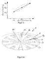
- FIG. 3 shows the heat output Q available at the exhaust gas outlet 4d as a function of the air inflow flow. If no supply air is supplied to the first supply air duct 2c, then the entire air flow C1 flows through the second supply air duct 2e, the heat output Q1 being present at the exhaust gas outlet 4d. If no supply air is supplied to the second supply air duct 2e, then the entire air flow C2 flows through the first supply air duct 2c, the heat output Q2 being present at the exhaust gas outlet 4d. In addition to the amount of air, the amount of fuel supplied is also changed accordingly. When simultaneously opened by the valve 8 supply air duct 2c and 2e, the total amount of air C3 flows partly through the first and partly through the second supply air duct 2c, 2e, wherein the heat output Q3 is applied to the exhaust gas outlet 4d.
- a three-way control valve 8 is used, which is configured as follows:
- the housing 7 has a base plate 8h with passage openings 8f and 8g, wherein the heat source 1 has partition walls and tubes designed such that the passage openings 8f open into the first supply air channel 2c and the passage openings 8g lead into the second supply air channel 2e.
- a cover 8e which is rotatable about the pivot bearing 8d and has passage openings 8g, 8f arranged such that either only the passage openings 8f or the passage openings 8g are completely opened, depending on the rotational position of the disc 8e that both the passage opening 8f and the passage opening 8g are partially opened.
- An air supply passage 9 is connected to the valve 8. Upstream could be arranged both at the air supply channel 9 and the fuel supply line 2a a pump 11, not shown.
- the passage openings 8g, 8f could also be arranged such that the cover 8e closes or opens the passage opening by a linear displacement.
- control valve 8 has two extreme positions in which only one of the two passage openings 8g, 8f is opened. In these two positions, the supplied airflow, as in FIG. 3 shown, the flow rate C 1 and C2, where C1, C2, for example, in the unit m 3 / s is shown, and the heat output at the exhaust outlet 4d has the value Q1 or Q2, where Q1, Q2, for example, in kilo joules (kJ) per second is shown.
- FIG. 2 shown control valve 8 also has the property that it is operable so that the distribution of the supply air flow between the first and the second channel 2c, 2e is variable.
- pump 11 By the air supply channel 9 upstream, not shown pump 11 also the amount of air per unit time of the supply air flow can be varied.
- the heat source 1 can thereby be controlled such that the heat output Q available at the exhaust gas outlet 4d can be varied as required in the range between Q1 and Q2 by dividing the supply air flow correspondingly between the first and the second channel 2c, 2e, and also if necessary, the amount of air per unit time and the amount of fuel per unit time via the pump 11 is driven accordingly.
- the valve 8 and the fuel pump 11 could also be configured so presettable that the valve 8 can be brought via the drive device in fixed predetermined positions, for example in 5 or 7 positions, each position of the valve 8 a predetermined heat output Q1 to Q7 result has, which as Low temperature heat is available especially for heating purposes.
- the heat or the temperature in the combustion chamber 3 and thereby the amount of heat transferred to the Stirling engine can also be influenced by a corresponding activation of the supplied supply air quantity and the amount of fuel supplied per unit time, so that the electrical power generated by the generator can also be influenced.
- the heat source is operated such that the heat or the temperature in the combustion chamber 3 remains constant, so that the generator generates a constant electric power, whereas the heat output can be varied.
- oil burner 2 could also be used a gas burner. It would have to be exchanged only designed as a fuel lance fuel supply line 2a. Otherwise the heat source 1 with gas burner would be identical to the one in FIG. 2 This feature provides the advantage that the heat source 1 for operation with a gas or oil burner is designed substantially identical, and that at any time a change from oil to gas operation or vice versa is possible by simply the fuel lance 2a is replaced. Otherwise, no changes to the heat source 1 Facultyt.
- FIGS. 4a . 4b and 4c show that in FIG. 2 illustrated three-way control valve 8 in detail.
- the control valve 8 can be actuated with a single, not shown drive means.
- the valve 8 comprises a fixed valve member 8h, which is configured as a circular base plate, with a plurality of circumferentially spaced inner fixed passage openings 8f and outer fixed passage openings 8g.
- the outer fixed passage openings 8g open, as in FIG. 2 shown, in the underlying second supply air duct 2e, whereas the inner fixed passage openings 8h open into the first supply air channel 2c.
- a movable valve member 8e arranged, which is designed in the illustrated embodiment as a rotatably mounted about a rotation axis 8d turntable 8e, wherein the hub 8e also has a plurality of circumferentially spaced apart inner rotatable passage openings 8i and outer rotatable passage openings 8k.
- the first total passage area F1 is the sum of the first partial passage areas f1 and the second total passage area F2 is the sum of the second partial passage areas f2, wherein the size of the partial passage areas f1, f2 and thus, of course, the total passage areas F1, F2 by the mutual position of the passage openings 8f and 8i respectively 8g and 8k is determined.
- FIG. 4a shows the turntable 8e in the already in FIG.
- FIG. 4c shows the turntable 8e in a position in which the inner passage openings 8f and 8i are fully opened, and the outer passage openings 8g and 8k are completely closed, so that the first part passage surfaces f1 are fully opened, and thereby also the total passage area F1.
- FIG. 4c shows the turntable 8e in a position in which the inner passage openings 8f and 8i are fully opened, and the outer passage openings 8g and 8k are completely closed, so that the first part passage surfaces f1 are fully opened, and thereby also the total passage area F1.
- FIG. 4b shows the hub 8e in an intermediate position in which both the first and the second partial passage surfaces f1 and f2 are partially opened, which means that the partial passage surfaces f1 and f2 or their total passage areas F1 and F2 have a smaller value than in FIG. 4a respectively Figure 4c position shown.
- both the first and the second supply air duct 2c, 2e supply air is supplied.
- FIG. 4b It can be seen that the total passage area F1 or F2 can be changed in the same way by rotating the turntable 8e by increasing the total passage area F1 of the first supply air flow A1 and reducing the total passage area F2 of the second supply air flow A2, or vice versa.
- the size of the total passage area F1 and F2 in response to the mutual displacement of movable valve member 8e to fixed valve member 8h is determined by means of the in FIGS. 4a to 4c illustrated rotary valve explained.
- the geometric configuration of the passage openings 8f, 8g, 8i and 8k and their mutual overlaps determined as a function of the angle of rotation the size of the total passage area F1 and F2 in function of the rotation angle of the turntable 8e.
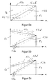
- the course of the total passage area F1 and the total passage area F2 as well as their sum F1 + F2 in function of the rotation angle ⁇ can, as in the Figures 5a, 5b and 5c shown, done in different ways.
- FIG. 5a shows the characteristics of the in the FIGS. 4a to 4c illustrated valve 8, as shown by 13a, in function of the rotation angle ⁇ constant sum F1 + F2, wherein the individual total passage areas F1 and F2 in function of the rotation angle, as shown by 13b, change linearly. This relationship could also be non-linear as shown by the dashed curve 13c. In this valve, therefore, the maximum value of the total passage areas F1 and F2 is the same size.
- FIG. 5b 13 shows the characteristic of a further valve 8 with a sum F1 + F2 decreasing as a function of the angle of rotation ⁇ , as illustrated by FIG. 13a, wherein the individual total passage areas F1 and F2 change linearly as a function of the angle of rotation, as illustrated in FIG. 13b.
- the maximum value of the total passage area F1 is thus greater than the maximum value of the total passage area F2.
- the course 13a and / or the course 13b could also run non-linearly, as shown by 13d, 13e.
- FIG. 5c shows the characteristic of another valve 8 with, as shown by 13a, as a function of the rotation angle ⁇ increasing sum F1 + F2 and linearly variable curve 13b.
- the maximum value of the total passage area F1 is thus smaller than the maximum value of the total passage area F2.
- the course 13a however, and / or the trace 13b could also be nonlinear as shown at 13d, 13e.
- the amount of air supplied to the combustion chamber 3 is the same as in FIGS FIGS. 5a to 5c shown course.
- the two supply air channels 2c and 2e of the heat source 1 usually have a different air resistance.
- linear characteristic has the consequence that the total of the combustion chamber 3 supplied amount of air changes in function of the rotation angle ⁇ .
- the valve 8, or its total passage surfaces F1 and F2 in function of the rotation angle ⁇ designed such that the effect of the different air resistances is compensated, and thus the total supplied via the supply air ducts 2c and 2e amount of air remains constant, regardless of the rotation angle ⁇ of the valve 8.
- FIGS. 5a to 5c shown relationship is of course not only for valves 8 with slidable by turning valve parts 8e. It could also be used a linearly displaceable valve member 8e.
- the in the FIGS. 5a to 5c shown relationship could also be achieved with two separate valves 8, wherein each of the two valves 8 one of the two total passage areas F1, F2 adjusts, so that by a corresponding control of the two valves 8 in the FIGS. 5a to 5c shown relationship can be generated.
Abstract
Description
Die Erfindung betrifft eine Wärmequelle gemäss dem Oberbegriff von Anspruch 1.The invention relates to a heat source according to the preamble of
Es ist bekannt mittels kleinen, dezentralen Blockheizkraftwerken aus Brennstoffenergie elektrische Energie und Heizungswärme zu erzeugen. Um diese kleinen Einheiten mit einem hohen elektrischen Wirkungsgrad zu betreiben sind Wärmequellen erforderlich, welche Temperaturen bis etwa 1000 °C erzeugen. Der Antrieb eines Stirling-Motors mit einer befeuerten Wärmequelle stellt höchste Ansprüche an die Befeuerung beziehungsweise an das Befeuerungsverfahren. Um mit dem Stirling-Motor einen hohen Wirkungsgrad zu erzielen ist im Brennraum der Wärmequelle ein heisses Gas mit einer möglichst hohen Temperatur erwünscht, ohne jedoch das Material des Stirlingmotors thermisch zu beschädigen. Diese hohen Temperaturen haben jedoch eine erhöhte Schadstoffemission (NOx und CO) zur Folge. Um diese gegensätzlichen Anforderungen optimal zu erfüllen werden Stirling-Motoren während dem Dauerbetrieb mit einer konstanten Wärmeleistung versorgt.It is known to produce electrical energy and heating heat by means of small, decentralized combined heat and power plants from fuel energy. In order to operate these small units with high electrical efficiency, heat sources are required which produce temperatures up to about 1000 ° C. The drive of a Stirling engine with a fired heat source places the highest demands on the firing system or on the firing process. In order to achieve high efficiency with the Stirling engine, a hot gas with the highest possible temperature is desired in the combustion chamber of the heat source, without, however, thermally damaging the material of the Stirling engine. However, these high temperatures result in increased pollutant emissions (NOx and CO). In order to optimally meet these conflicting requirements, Stirling engines are supplied with a constant heat output during continuous operation.
Die Druckschrift
Aufgabe der Erfindung ist es eine Wärmequelle für ein Blockheizkraftwerk zu bilden, welche eine variierbare Heizleistung aufweist. Eine weitere Aufgabe der Erfindung ist es die Wärmequelle derart auszubilden, dass diese mit unterschiedlichen Brennstoffen betreibbar ist.The object of the invention is to form a heat source for a combined heat and power plant, which has a variable heat output. Another object of the invention is to design the heat source such that it can be operated with different fuels.
Diese Aufgabe wird gelöst mit einer Wärmequelle aufweisend die Merkmale von Anspruch 1. Die Unteransprüche 2 bis 9 betreffen weitere, vorteilhaft ausgestaltete Wärmequellen. Die Aufgabe wird weiter gelöst mit einem Verfahren zum Betrieb einer Wärmequelle aufweisend die Merkmale von Anspruch 10.This object is achieved with a heat source having the features of
Die Aufgabe wird insbesondere gelöst mit einer Wärmequelle umfassend eine Brennkammer zur Erzeugung von Wärme mit hohem Temperaturniveau, sowie umfassend einen in die Brennkammer mündenden Brenner und einen Wärmetauscher, wobei die Brennkammer Fluid leitend mit einem Abgaskanal verbunden ist, welcher durch den Wärmetauscher verläuft, und wobei die Wärmequelle einen ersten und einen zweiten Fluid leitenden Kanal umfasst, über welche ein Zuluftstrom der Brennkammer zuführbar ist, wobei der erste Kanal derart verläuft, dass der Zuluftstrom ohne einen Wärmeaustausch mit Abgasen der Brennkammer zugeleitet ist, und wobei der zweite Kanal durch den Wärmetauscher verlaufend der Brennkammer zugeleitet ist, und wobei ein Regelventil derart wirkend angeordnet ist, dass die Verteilung des Zuluftstroms zwischen dem ersten und dem zweiten Kanal variierbar ist.The object is achieved in particular with a heat source comprising a combustion chamber for generating heat with a high temperature level, and comprising one in the combustion chamber opening burner and a heat exchanger, wherein the combustion chamber fluid is conductively connected to an exhaust passage which passes through the heat exchanger, and wherein the heat source comprises a first and a second fluid-conducting channel, via which a supply air flow to the combustion chamber can be fed, wherein the first channel is such that the supply air flow is supplied without heat exchange with exhaust gases of the combustion chamber, and wherein the second channel is fed through the heat exchanger extending the combustion chamber, and wherein a control valve is arranged to act such that the distribution of the supply air flow between the first and the second Channel is variable.
Unter dem Begriff Zuluftstrom wird hierin ein Zustrom aus Luft oder auch einem anderen Oxidationsmittel verstanden. Vorzugsweise wird jedoch Luft als Zustrom verwendet.The term supply air flow is understood herein to mean an influx of air or other oxidizing agent. Preferably, however, air is used as the feed.
Die erfindungsgemässe Wärmequelle umfasst eine Brennkammer sowie einen Wärmetauscher, wobei die Brennkammer über einen Abgaskanal Fluid leitend mit dem Wärmetauscher verbunden ist. Die erfindungsgemässe Wärmequelle umfasst zwei unterschiedliche Zuluftströme, beziehungsweise zwei unterschiedlich verlaufende, Fluid leitende Kanäle, über welche der Brennkammer Luft zugeleitet wird. Ein erster Kanal verläuft ohne einen Wärmetausch mit Abgasen in die Brennkammer, vorzugsweise von ausserhalb der Wärmequelle auf direkten Wege in die Brennkammer, sodass der Brennkammer über diesen ersten Kanal ein Zuluftstrom mit relativ kühler Luft, üblicherweise mit einer Temperatur von Umgebungsluft, zugeführt wird. Ein zweiter Kanal verläuft über den Wärmetauscher, in welchem Wärme mit dem Abgas ausgetauscht wird, sodass der Brennkammer über diesen zweiten Kanal ein Zuluftstrom mit sehr heisser Luft, mit einer hohen Temperatur von beispielsweise 500 - 700°C zugeführt wird. Die erfindungsgemässe Wärmequelle umfasst ein Regelventil, mit welchem die Verteilung des Zuluftstroms zwischen erstem und zweitem Kanal steuerbar ist, was den Vorteil ergibt, dass die von der Wärmequelle über das Abgas abgegebene Wärmeleistung ansteuerbar ist. Die Wärme in der Brennkammer lässt sich zudem über die zugeführte Menge Brennstoff, welche in der Brennkammer verbrennt, beeinflussen. Daher kann die von der erfindungsgemässen Wärmequelle abgegebene Wärmeleistung beispielsweise mit folgendem Verfahren variiert werden: Die Temperatur des Gases innerhalb der Brennkammer wird auf einem konstanten oder annähernd konstanten Wert gehalten, um den Stirling-Motor mit einem konstant hohen Wirkungsgrad zu betreiben. Um die von der Wärmequelle abgegebene Wärmeleistung zu erhöhen wird über den ersten Kanal mehr Zuluft und über den zweiten Kanal weniger Zuluft der Brennkammer zugeführt. Zudem wird dem Brenner mehr Brennstoff zugeführt, vorzugsweise derart, dass die Temperatur des Gases in der Brennkammer konstant oder annähernd konstant bleibt. Dies hat zur Folge, dass die Stirlingmaschine mit konstantem Wert betreibbar ist, wogegen die aus der Wärmequelle am kalten Ende des Rekuperators austretenden Abgase eine Niedertemperaturwärme mit höherer Wärmeleistung aufweisen, welche für Heizzwecke genutzt werden kann.The heat source according to the invention comprises a combustion chamber and a heat exchanger, the combustion chamber being conductively connected to the heat exchanger via an exhaust gas channel. The inventive heat source comprises two different supply air flows, or two differently extending, fluid-conducting channels, via which the combustion chamber air is supplied. A first channel runs without heat exchange with exhaust gases into the combustion chamber, preferably from outside the heat source on direct routes into the combustion chamber, so that the combustion chamber via this first channel a supply air flow with relatively cool air, usually at a temperature of ambient air, is supplied. A second channel passes through the heat exchanger, in which heat is exchanged with the exhaust gas, so that the combustion chamber via this second channel a supply air flow with very hot air, with a high temperature of for example 500 - 700 ° C is supplied. The inventive heat source comprises a control valve, with which the distribution of the supply air flow between the first and second channel is controllable, which results in the advantage that the output of the heat source via the exhaust heat output can be controlled. The heat in the combustion chamber can also be influenced by the amount of fuel that is burned in the combustion chamber. Therefore, the heat output from the heat source of the present invention can be varied by, for example, the following method. The temperature of the gas within the combustion chamber is maintained at a constant or approximately constant value to operate the Stirling engine at a consistently high efficiency. To increase the output from the heat source heat output is supplied via the first channel more supply air and the second channel less supply air to the combustion chamber. In addition, more fuel is supplied to the burner, preferably such that the temperature of the gas in the combustion chamber remains constant or approximately constant. This has the consequence that the Stirling engine can be operated with a constant value, whereas the exiting from the heat source at the cold end of the recuperator exhaust gases have a low-temperature heat with higher heat output, which can be used for heating purposes.
Ein Blockheizkraftwerk betrieben mit der erfindungsgemässen Wärmequelle weist somit den Vorteil auf, dass die zum Heizen zur Verfügung stehende Wärmeleistung variierbar ist.A combined heat and power plant operated with the heat source according to the invention thus has the advantage that the heat output available for heating can be varied.
In einem einfachen Betriebsverfahren erzeugt die Wärmequelle nur zwei unterschiedliche Wärmeleistungen, eine geringere oder eine höhere abgegebene Wärmeleistung, indem die Zuluft entweder nur über den ersten oder nur über den zweiten Kanal der Brennkammer zugeführt wird. Dabei wird der Brennkammer vorzugsweise derart viel Brennstoff zugeführt, dass die Temperatur des Gases in der Brennkammer konstant bleibt. Ein Blockheizkraftwerk betrieben mit diesem einfachen Betriebsverfahren weist somit eine konstante, über den Stirling-Motor und dessen Generator erzeugte elektrische Leistung auf, wogegen die abgegebene Wärmeleistung zwischen einem geringen Wert, beispielsweise 6 kW und einem hohen Wert, beispielsweise 9 kW gewählt werden kann.In a simple operating method, the heat source generates only two different heat outputs, one lower or one lower higher output heat output by the supply air is supplied either only via the first or only via the second channel of the combustion chamber. In this case, the combustion chamber is preferably supplied with so much fuel that the temperature of the gas in the combustion chamber remains constant. A combined heat and power plant operated with this simple operating method thus has a constant electric power generated by the Stirling engine and its generator, whereas the heat output power can be selected between a low value, for example 6 kW and a high value, for example 9 kW.
In einem anspruchsvolleren Betriebsverfahren stehen als abgegebene Wärmeleistung nicht nur die beiden Eckwerte (geringer Wert / hoher Wert) zur Verfügung, sondern auch die zwischen diesen Werten liegenden Wärmeleistungen, sodass die abgegebene Wärmeleistung veränderbar beziehungsweise modulierbar ist. Um dies zu erreichen wird der Brennkammer sowohl über den ersten als auch den zweiten Kanal Zuluft zugeführt, wobei diese beiden zugeführten Teilströme Zuluft und die zugeführte Menge Brennstoff vorzugsweise derart dosiert wird, dass die Temperatur in der Brennkammer einen etwa konstanten Wert aufweist, und die abgegebene Wärmemenge dem gewünschten Wert entspricht. Dieses anspruchsvollere Betriebsverfahren weist den Vorteil auf, dass der Stirling-Motor mit konstant hohem Wirkungsgrad betreibbar ist, und die von der Wärmequelle abgegebene Wärmeleistung, welche vorteilhafter weise zu Heizzwecken verwendet wird, bezüglich den jeweiligen Erfordernissen variierbar ist. Ein derartiges Blockheizkraftwerk weist somit den Vorteil auf, dass der insbesondere im Winter erhöhte und schwankende Wärmeleistungsbedarf zum Beheizen eines Hauses ohne zusätzlichen Brenner bereitgestellt werden kann.In a more demanding operating method, not only the two basic values (low value / high value) are available as output heat output, but also the heat outputs lying between these values, so that the output heat output can be changed or modulated. To achieve this, the combustion chamber is supplied with supply air both via the first and the second channel, wherein these two supplied partial streams supply air and the amount of fuel supplied is preferably metered such that the temperature in the combustion chamber has an approximately constant value, and the discharged Amount of heat corresponds to the desired value. This more demanding method of operation has the advantage that the Stirling engine can be operated with constant high efficiency, and the heat output from the heat source, which is advantageously used for heating purposes, is variable with respect to the respective requirements. Such a combined heat and power plant thus has the advantage that the increased in particular in winter and fluctuating heat output requirement for heating a house without additional burner can be provided.
Die erfindungsgemässe Wärmequelle kann beispielsweise mit Öl, Gas oder einem vergasten Feststoff betrieben werden. Der vergaste Feststoff wird beispielsweise durch Pyrolyse gewonnen. Die Wärmequelle kann auch derart ausgestaltet sein, dass dieselbe Wärmequelle mit Öl oder Gas oder vergastem Feststoff betreibbar ist.The inventive heat source can be operated for example with oil, gas or a gasified solid. The gasified solid is obtained, for example, by pyrolysis. The heat source can also be designed such that the same heat source with oil or gas or gasified solid is operable.
Die zur Erläuterung der Ausführungsbeispiele verwendeten Zeichnungen zeigen:
-
Fig. 1 eine bekannte Wärmequelle im Längsschnitt; -
Fig. 2 eine erfindungsgemässe, schematisch dargestellte Wärmequelle im Längsschnitt; -
Fig. 3 eine Grafik der erzeugten, variierbaren Wärmeleistung, -
Fig. 4a eine perspektivische Ansicht eines als Dreiwegventil ausgestalteten Regelventils; -
Fig. 4b das inFigur 4a -
Fig. 4c das inFigur 4a
-
Fig. 1 a known heat source in longitudinal section; -
Fig. 2 an inventive, schematically illustrated heat source in longitudinal section; -
Fig. 3 a graph of the generated, variable heat output, -
Fig. 4a a perspective view of a designed as a three-way valve control valve; -
Fig. 4b this inFIG. 4a illustrated control valve in half-open position; -
Fig. 4c this inFIG. 4a illustrated control valve with an open and a closed channel.
Grundsätzlich sind in den Zeichnungen gleiche Teile mit gleichen Bezugszeichen versehen.Basically, the same parts are given the same reference numerals in the drawings.
Die Brennkammer 3 der Wärmequelle 1 ist von einer Innenisolation 5 sowie einer Aussenisolation 6 umgeben. Zwischen der Innen- und Aussenisolation 5, 6 verläuft ein nur schematisch dargestellter Wärmetauscher 4, welcher eine Trennwand 4a, einen Teilabschnitt des zweiten Luftkanals 2e, sowie einen Teilabschnitt das Abgaskanals 4c umfasst. Der Abgaskanal 4c beginnt an der Austrittsöffnung 4b der Brennkammer 3 und leitet den Abgasstrom B über den Wärmetauscher 4 dem Abgasauslass 4d zu. Am Abgasauslass 4d ist ein Wasser leitendes Wärmeaufnahmerohr 12 angeordnet, welches dem Abgasstrom B Wärme für Heizzwecke entzieht. Zwischen der Aussenwand 7 und der Aussenisolation 6 verläuft im dargestellten Ausführungsbeispiel der zweite Zuluftkanal 2e nach unten, und ist danach über den Wärmetauscher 4 und die Austrittsöffnung 2d in den Brennraum 3 geleitet. Der Kopf einer Stirlingmaschine 10, welcher nur schematisch angedeutet ist, ragt in den Brennraum 3 hinein, um derart beheizt zu werden.The combustion chamber 3 of the
Die beiden Zuluftkanäle 2c, 2e sind mit einem Ventil 8 versehen, um die zufliessende Luftmenge pro Zeiteinheit anzusteuern. Jeder Zuluftkanal 2c, 2e könnte mit einem separaten, individuell ansteuerbaren Regelventil 8, beispielsweise je einem elektromagnetischen Auf-Zu-Ventil, versehen sein. In der einfachsten Ausgestaltung ist jedes Regelventil 8 als Auf-Zu-Ventile ausgestaltet, welche nur eine Offen- und eine Geschlossenstellung einnehmen können. Dies erlaubt entweder nur dem ersten Zuluftkanal 2c, oder nur dem zweiten Zuluftkanal 2e, oder sowohl dem ersten als auch dem zweiten Zuluftkanal 2c, 2e Luft zuzuführen. Um die Abgastemperatur in der Brennkammer 3 ungefähr konstant zu halten ist beim Schalten der Regelventile 8 zudem die über die Brennstoffdüse 2b zugeleitete Brennstoffmenge anzupassen. Dies ermöglicht die Wärmequelle vorzugsweise derart zu betreiben, dass die vom Stirlingmotor in der Brennkammer 3 abgeführte Wärmeleistung konstant bleibt, sodass der mit dem Stirlingmotor verbundene Generator eine konstante elektrische Leistung erzeugt, wogegen die über das Abgas B am Auslass 4d zur Verfügung stehende Wärmeleistung, wie in
Im Ausführungsbeispiel gemäss
Das in
Durch ein entsprechendes Ansteuern der zugeführten Zuluftmenge sowie der zugeführten Brennstoffmenge pro Zeiteinheit kann auch die Wärme beziehungsweise die Temperatur in der Brennkammer 3 und dadurch die an den Stirlingmotor übertragene Wärmemenge beeinflusst werden, sodass auch die vom Generator erzeugte elektrische Leistung beeinflussbar ist. Bevorzugt wird die Wärmequelle jedoch derart betrieben, dass die Wärme beziehungsweise die Temperatur in der Brennkammer 3 konstant bleibt, sodass der Generator eine konstante elektrische Leistung erzeugt, wogegen die abgegebene Wärmeleistung variiert werden kann.The heat or the temperature in the combustion chamber 3 and thereby the amount of heat transferred to the Stirling engine can also be influenced by a corresponding activation of the supplied supply air quantity and the amount of fuel supplied per unit time, so that the electrical power generated by the generator can also be influenced. Preferably, however, the heat source is operated such that the heat or the temperature in the combustion chamber 3 remains constant, so that the generator generates a constant electric power, whereas the heat output can be varied.
Anstelle des in
Die
Die Grösse der Gesamtdurchtrittsfläche F1 und F2 in Abhängigkeit der gegenseitigen Verschiebung von beweglichem Ventilteils 8e zu feststehendem Ventilteil 8h wird mit Hilfe des in den
Sofern die beiden Zuluftkanäle 2c und 2e der Wärmequelle 1 denselben Luftwiderstand aufweisen, weist die der Brennkammer 3 zugeführte Luftmenge denselben, wie in den
Der in den
Claims (11)
Priority Applications (1)
| Application Number | Priority Date | Filing Date | Title |
|---|---|---|---|
| EP06124859A EP1925884A1 (en) | 2006-11-27 | 2006-11-27 | Heat source |
Applications Claiming Priority (1)
| Application Number | Priority Date | Filing Date | Title |
|---|---|---|---|
| EP06124859A EP1925884A1 (en) | 2006-11-27 | 2006-11-27 | Heat source |
Publications (1)
| Publication Number | Publication Date |
|---|---|
| EP1925884A1 true EP1925884A1 (en) | 2008-05-28 |
Family
ID=38110424
Family Applications (1)
| Application Number | Title | Priority Date | Filing Date |
|---|---|---|---|
| EP06124859A Withdrawn EP1925884A1 (en) | 2006-11-27 | 2006-11-27 | Heat source |
Country Status (1)
| Country | Link |
|---|---|
| EP (1) | EP1925884A1 (en) |
Cited By (1)
| Publication number | Priority date | Publication date | Assignee | Title |
|---|---|---|---|---|
| AT513734A1 (en) * | 2012-12-04 | 2014-06-15 | Kofen Forschungs Und Entwicklungsgesellschaft M B H | Boiler with heat engine |
Citations (4)
| Publication number | Priority date | Publication date | Assignee | Title |
|---|---|---|---|---|
| DE2339639A1 (en) * | 1972-08-24 | 1974-03-07 | Philips Nv | HOT GAS ENGINE WITH A BURNER DEVICE WITH A BURNER CHAMBER, THE SMOKE GAS EXHAUST OF THAT CONNECTED TO A ROOM WITH A HEATER |
| US3848412A (en) * | 1970-03-06 | 1974-11-19 | Philips Corp | Method of supplying thermal energy to the heater of a hot-gas engine, as well as a hot-gas engine comprising a device for carrying out the method |
| US4480986A (en) * | 1983-09-14 | 1984-11-06 | Sea-Labs, Inc. | Liquid fuel vaporizing burner |
| WO2001065099A2 (en) * | 2000-03-02 | 2001-09-07 | New Power Concepts Llc | Stirling engine thermal system improvements |
-
2006
- 2006-11-27 EP EP06124859A patent/EP1925884A1/en not_active Withdrawn
Patent Citations (4)
| Publication number | Priority date | Publication date | Assignee | Title |
|---|---|---|---|---|
| US3848412A (en) * | 1970-03-06 | 1974-11-19 | Philips Corp | Method of supplying thermal energy to the heater of a hot-gas engine, as well as a hot-gas engine comprising a device for carrying out the method |
| DE2339639A1 (en) * | 1972-08-24 | 1974-03-07 | Philips Nv | HOT GAS ENGINE WITH A BURNER DEVICE WITH A BURNER CHAMBER, THE SMOKE GAS EXHAUST OF THAT CONNECTED TO A ROOM WITH A HEATER |
| US4480986A (en) * | 1983-09-14 | 1984-11-06 | Sea-Labs, Inc. | Liquid fuel vaporizing burner |
| WO2001065099A2 (en) * | 2000-03-02 | 2001-09-07 | New Power Concepts Llc | Stirling engine thermal system improvements |
Cited By (2)
| Publication number | Priority date | Publication date | Assignee | Title |
|---|---|---|---|---|
| AT513734A1 (en) * | 2012-12-04 | 2014-06-15 | Kofen Forschungs Und Entwicklungsgesellschaft M B H | Boiler with heat engine |
| AT513734B1 (en) * | 2012-12-04 | 2022-12-15 | Oekofen Forschungs Und Entw M B H | Boiler with heat engine |
Similar Documents
| Publication | Publication Date | Title |
|---|---|---|
| EP3186498B1 (en) | Gas turbine arrangement | |
| EP1330953B1 (en) | Burner system with multiple heat transfer systems and cooking device having such burner system | |
| DE10216749A1 (en) | Four-way mixing valve | |
| AT505769B1 (en) | OVEN | |
| DE2364455C3 (en) | Electric heater | |
| DE10012485B4 (en) | Device for controlling the supply of combustion air to the combustion chamber of a single fireplace, for example an oven, stove, stove or the like | |
| EP1925884A1 (en) | Heat source | |
| DE2223655B2 (en) | Device for preheating the sucked-in fuel-air mixture through the exhaust gases in internal combustion engines with controlled spark ignition, in particular in motor vehicles | |
| EP2071243B1 (en) | Combustion assembly, in particular stoves or tiled stoves | |
| EP1925883A1 (en) | Heat source with controlable fuel oil supply and method for operating the same | |
| DE69929769T2 (en) | Burner assembly and burner head for gas mixture combustion | |
| EP1455079B1 (en) | Heat transfer device between the exhaust gas of an internal combustion engine and a cooling fluid | |
| DE19947879B4 (en) | Heating arrangement with a burner-heated heater | |
| DE202014002500U1 (en) | heating system | |
| LU85944A1 (en) | DIRECTLY FIRED AIR HEATER WITH HEATING UNIT FOR A WARM AIR HEATING | |
| DE69908023T2 (en) | Improvement in combustion devices with multiple combustion air supply channels | |
| DE19757931A1 (en) | Device for recirculating exhaust gas and for preheating an exhaust gas cleaner | |
| DE102006037607A1 (en) | Air-heater for use in cold climates has two blowers are located in a duct upstream of the first combustion chamber and operate in parallel | |
| DE202004015288U1 (en) | Device to disperse exhaust gases from cooker combustion chamber has downstream heat exchanger, in hot air steam or microwave device for heating food, and circulation blower whereby combustion chamber is formed as dispersing exhaust chamber | |
| DE2842384A1 (en) | Mixing valve for low-temp. water - has additional warm supply for mixing with cold or hot water | |
| DE19706626A1 (en) | Exhaust fume system for internal combustion engine of motor vehicle | |
| DE2163822C3 (en) | Gas turbine engine with heat exchanger | |
| DE2715702A1 (en) | AIR HEATER | |
| WO2010020286A1 (en) | Multi-cylinder internal combustion engine | |
| DE2728897A1 (en) | Flue gas duct control for boilers - closes duct and opens ventilator at burner shut=down and vice=versa |
Legal Events
| Date | Code | Title | Description |
|---|---|---|---|
| PUAI | Public reference made under article 153(3) epc to a published international application that has entered the european phase |
Free format text: ORIGINAL CODE: 0009012 |
|
| AK | Designated contracting states |
Kind code of ref document: A1 Designated state(s): AT BE BG CH CY CZ DE DK EE ES FI FR GB GR HU IE IS IT LI LT LU LV MC NL PL PT RO SE SI SK TR |
|
| AX | Request for extension of the european patent |
Extension state: AL BA HR MK RS |
|
| 17P | Request for examination filed |
Effective date: 20081127 |
|
| AKX | Designation fees paid | ||
| REG | Reference to a national code |
Ref country code: DE Ref legal event code: 8566 |
|
| RAP1 | Party data changed (applicant data changed or rights of an application transferred) |
Owner name: CLEANERGY AB |
|
| RBV | Designated contracting states (corrected) |
Designated state(s): AT BE BG CH CY CZ DE DK EE ES FI FR GB GR HU IE IS IT LI LT LU LV MC NL PL PT RO SE SI SK TR |
|
| 17Q | First examination report despatched |
Effective date: 20090504 |
|
| STAA | Information on the status of an ep patent application or granted ep patent |
Free format text: STATUS: THE APPLICATION IS DEEMED TO BE WITHDRAWN |
|
| 18D | Application deemed to be withdrawn |
Effective date: 20090915 |