EP1925848A1 - Eccentrically rocking type reduction gear - Google Patents
Eccentrically rocking type reduction gear Download PDFInfo
- Publication number
- EP1925848A1 EP1925848A1 EP06797931A EP06797931A EP1925848A1 EP 1925848 A1 EP1925848 A1 EP 1925848A1 EP 06797931 A EP06797931 A EP 06797931A EP 06797931 A EP06797931 A EP 06797931A EP 1925848 A1 EP1925848 A1 EP 1925848A1
- Authority
- EP
- European Patent Office
- Prior art keywords
- outer teeth
- crankshafts
- gear
- speed reducer
- crankshaft
- Prior art date
- Legal status (The legal status is an assumption and is not a legal conclusion. Google has not performed a legal analysis and makes no representation as to the accuracy of the status listed.)
- Granted
Links
Images



Classifications
-
- F—MECHANICAL ENGINEERING; LIGHTING; HEATING; WEAPONS; BLASTING
- F16—ENGINEERING ELEMENTS AND UNITS; GENERAL MEASURES FOR PRODUCING AND MAINTAINING EFFECTIVE FUNCTIONING OF MACHINES OR INSTALLATIONS; THERMAL INSULATION IN GENERAL
- F16H—GEARING
- F16H1/00—Toothed gearings for conveying rotary motion
- F16H1/28—Toothed gearings for conveying rotary motion with gears having orbital motion
- F16H1/32—Toothed gearings for conveying rotary motion with gears having orbital motion in which the central axis of the gearing lies inside the periphery of an orbital gear
Definitions
- the present invention relates to an eccentrically oscillating speed reducer including a gear between crankshafts for transmitting a power inputted to one crankshaft of a plurality of crankshafts to remaining crankshafts.
- Patent Reference 1 JP-A-9-57678 (pages 3, 4, Figs 1 , 3 )
- the invention has been carried out in order to resolve the problem of the background art and it is an object thereof to provide an eccentrically oscillating speed reducer capable of reducing a number of parts more than that of the background art.
- An eccentrically oscillating speed reducer of the invention is constructed by a constitution including a first member having inner teeth, a plurality of crankshafts having outer teeth, an outer teeth member having outer teeth brought in mesh with the inner teeth of the first member and eccentrically moved by the crankshaft, a second member rotatably supporting the crankshafts and rotated to move relative to the first member by the crankshafts, and an inter-crankshaft gear brought in mesh with the outer teeth of the crankshafts to be rotatably supported and transmitting a power inputted to one crankshaft of the plurality of crankshafts to a remaining crankshaft.
- the eccentrically oscillating speed reducer of the invention there are not a pair of rolling bearings as in the background art for supporting the inter-crankshaft gear, and therefore, a number of parts can be reduced more than the background art.
- the inter-crankshaft gear is brought in mesh with the outer teeth of the crankshafts substantially at a middle portion between both ends of the crankshafts, even when the crankshafts are bent, the outer teeth of the crankshafts and the inter-crankshaft gear are difficult to be inclined, and the inter-crankshaft gear and the outer teeth of the crankshafts are brought in mesh with each other substantially uniformly in a tooth trace direction.
- the eccentrically oscillating speed reducer of the invention may be constructed by a constitution in which the inter-crankshaft gear includes outer teeth brought in mesh with the outer teeth of the crankshafts.
- the inter-crankshaft gear is small-sized and fabrication cost can be reduced.
- the eccentrically oscillating speed reducer of the invention may be constructed by a constitution in which the inter-crankshaft gear includes inner teeth brought in mesh with the outer teeth of the crankshafts.
- the eccentrically oscillating speed reducer of the invention may be constructed by a constitution in which the inter-crankshaft gear frictionally slides relative to the outer teeth member by way of an oil film.
- the eccentrically oscillating speed reducer of the invention can restrict the inter-crankshaft gear in an axial direction.
- the eccentrically oscillating speed reducer of the invention may be constructed by a constitution further including a bearing for rotatably supporting the second member relative to the first member, wherein an inter-crankshaft gear frictionally slides relative to the outer teeth member and the bearing by way of oil films.
- a bearing having a high hardness for rotatably supporting the second member relative to the first member is utilized also for supporting the inter-crankshaft gear, and therefore, in comparison with a constitution in which the inter-crankshaft gear is supported by a member having a low hardness, reduction of service life by wear of the member can be prevented.
- the inter-crankshaft gear can be restricted in the axial direction by making the inter-crankshaft gear frictionally slide relative to the outer teeth member and the bearing.
- the eccentrically oscillating speed reducer of the invention may be constructed by a constitution in which a through hole is formed substantially at a center of the second member, wherein the through hole is arranged on an inner side of the inter-crankshaft gear.
- the inter-crankshaft gear is not supported by a rolling bearing as in the background art, and therefore, a diameter of the through hole can be made to be larger than that of the background art by an amount of a portion supported by the rolling bearing which is not provided to the inter-crankshaft gear.
- the eccentrically oscillating speed reducer of the invention may be constructed by a constitution in which the second member includes a gear inserting part inserted to the inter-crankshaft gear.
- a space at inside of the speed reducer and a through hole are separated by the gear inserting part, and therefore, even when a lubricant is sealed to the space at inside of the speed reducer, the lubricant sealed to the space at inside of the speed reducer can be prevented from leaking out to the through hole.
- the eccentrically oscillating speed reducer of the invention may be constructed by a constitution including a plurality of the outer teeth members, wherein the inter-crankshaft gear is arranged between the plurality of outer teeth members.
- the inter-crankshaft gear is brought in mesh with the outer teeth of the crankshafts at substantially a middle portion between the bearings installed at both ends of the crankshafts for supporting the crankshafts, and therefore, even when the crankshafts are bent, the outer teeth of the crankshafts and the inter-crankshaft gear are difficult to be inclined and the inter-crankshaft gear and the outer teeth of the crankshafts are brought in mesh with each other substantially uniformly in a tooth trace direction.
- the invention can provide the eccentrically oscillating speed reducer capable of reducing a number of parts more than that of the background art.
- a joint 10 of an industrial robot includes an arm 20, an arm 30 turning relative to the arm 20, amotor 40 fixed to the arm 30 and generating a power for rotating the arm 30 relative to the arm 20, and an eccentrically oscillating speed reducer 100 fixed to the arm 20 and the arm 30 and constituting a power of the arm 30 relative to the arm 20 by the power generated by the motor 40 by reducing a speed thereof.
- the eccentrically oscillating speed reducer 100 includes a case 110 constituting a first member having inner teeth 110a, a crankshaft 121 having an eccentric portion 121a, an eccentric portion 121b and outer teeth 121c, a crankshaft 122 (refer to Fig.
- the case 110 includes a pin 111 for forming the inner teeth 110a, and a pin support member 112 embedded with the pin 111.
- crankshafts 121, 122, and 123 are arranged to be remote from each other by 120° on a circumference centering on a center point of a gear of the inner teeth 110a of the case 110.
- the carrier 140 includes a circular plate 141 having a column portion 141a inserted to a hole 131c of the outer teeth gear 131 and a hole 132c of the outer teeth gear 132, a circular plate 142 arranged at a position of interposing the outer teeth gears 131 and 132 along with the circular plate 141, a hollow cylinder 143 constituting a gear inserting part both ends of which are fixed by the circular plate 141 and the circular plate 142 and which is inserted into the cylindrical gear 180, an O ring 144 for sealing a gap of the circular plate 141 and the hollow cylinder 143, an O ring 145 for sealing a gap of the circular plate 142 and the hollow cylinder143, apositioningpin146forpositioningthecircular plates 141 and 142, and a bolt 147 for fastening the circular plates 141 and 142.
- Respective pluralities of the column portions 141a, the positioning pins 146, and the bolts 147 are arranged on a circumference centering on a center point of the gear of the inner teeth 110a of the case 110. Further, the carrier 140 is formed with a groove 140a containing the input gear 151 and the outer gear 152.
- the cylindrical gear 180 is arranged between the outer teeth gear 131 and the outer teeth gear 132 and rotatably supported by being brought in mesh with the outer teeth 121c, 122c, and 123c of the crankshafts 121, 122 and 123. Further, the cylindrical gear 180 is rotatably supported by producing sliding friction at portions thereof in contact with the outer teeth gears 131 and 132 by way of oil films.
- the through hole 101 is constituted by a hole 141b of the circular plate 141, a hole 142a of the circular plate 142 and a hole 143a of the hollow cylinder 143.
- a joint 10 includes a bolt 51 for fixing the arm 20 and the case 110, a bolt 52 for fixing the arm 30 and the motor 40, a bolt 53 for fixing the arm 30 and the circular plate 141, a hole 30a of the arm 30 and a wiring 60 passing the through hole 101 of the eccentrically oscillating speed reducer 100.
- respective pluralities of the bolts 51 and 53 are arranged on a circumference centering on the axis line of the eccentrically oscillating speed reducer 100.
- a plurality of the bolts 52 are arranged on a circumference centering on an axis line of the output shaft 41 and the motor 40.
- engaging faces of the arm 30 and the motor 40 and engaging faces of the arm 30 and the circular plate 141 are respectively sealed by a seal agent or the like.
- the power generated by the motor 40 is transmitted to the crankshaft 121 by way of the input gear 151 attached to the output shaft 41 of the motor 40 and the outer gear 152 attached to the crankshaft 121 by reducing a speed thereof and is transmitted to the cylindrical gear 180 by way of the outer teeth 121c of the crankshaft 121 and the outer teeth 181 of the cylindrical gear 180.
- the power transmitted to the cylindrical gear 180 is transmitted to the crankshaft 122 by way of the outer teeth 181 of the cylindrical gear 180 and the outer teeth 122c of the crankshaft 122 and transmitted to the crankshaft 123 by way of the outer teeth 181 of the cylindrical gear 180 and the outer teeth 123c of the crankshaft 123.
- the power transmitted to the crankshafts 121, 122, and 123 is transmitted to the outer teeth gears 131 and 132 by way of the eccentric portions 121a and 121b of the crankshaft 121 and the eccentric portions of the crankshafts 122 and 123 and is transmitted to the carrier 140 by reducing a speed thereof by way of the outer teeth 131a and 132a of the outer teeth gears 131 and 132, and the inner teeth 110a of the case 110.
- the carrier 140 is rotated relative to the case 110 and the arm 30 fixed to the carrier 140 is rotated relative to the arm 20 fixed with the case 110.
- the cylindrical gear 180 is brought in mesh with the outer teeth 121c, 122c, and 123c of the crankshafts 121, 122, and 123 to be rotatably supported, and there are not a pair of rolling bearings as in the background art for supporting the cylindrical gear 180, and therefore, a number of parts can be reduced more than that of the background art.
- the cylindrical gear 180 is not supported by the rolling bearings as in the background art, and therefore, a diameter of the through hole 101 can be made to be larger than that of the background art by an amount of dispensing with a portion supported by the rolling bearing which is not provided by the cylindrical gear 180.
- the cylindrical gear 180 includes the outer teeth 181 brought in mesh with the outer teeth 121c, 122c, and 123c of the crankshafts 121, 122, and 123, and therefore, the cylindrical gear 180 is small-sized in comparison with a constitution in which the inter-crankshaft gear includes the inner teeth brought in mesh with the outer teeth 121c, 122c, 123c of the crankshafts 121, 122, 123.
- the eccentrically oscillating speed reducer 100 in comparison with a constitution in which the inter-crankshaft gear includes the inner teeth brought in mesh with the outer teeth 121c, 122c, and 123c of the crankshafts 121, 122, and 123, fabrication cost can be reduced.
- the hollow cylinder 143 is inserted into the cylindrical gear 180 to separate a space at inside of the speed reducer and the through hole 101 by the hollow cylinder 143, and therefore, even when a lubricant is sealed at the space at inside of the speed reducer, the lubricant sealed at the space at inside of the speed reducer can be prevented from leaking out to the through hole 101.
- the cylindrical gear 180 is arrangedbetween the outer teeth gear 131 and the outer teeth gear 132, the cylindrical gear 180 is brought in mesh with the outer teeth 121c, 122c, and 123c of the crankshafts 121, 122, and 123 substantially at a middle portion between the bearings 175 and 176 arranged at both ends of the crankshaft 121 for supporting the crankshaft 121 and substantially a middle portion between bearings installed at both ends of the crankshafts 122 and 123 for supporting the crankshafts 122 and 123, and therefore, even when the crankshafts 121, 122, and 123 are bent, the outer teeth 121c, 122c, and 123c of the crankshafts 121, 122, and 123 and the cylindrical gear 180 are difficult to be inclined, and the cylindrical gear 180 and the outer teeth 121c, 122c, and 123c of the crankshafts 121, 122, and 123 are brought in mesh with each other substantially
- a difference of an outer diameter of the cylindrical gear 180 and an outer diameter of the hollow cylinder 143 is always larger than a distance 100a between a face of forming the hole 131d of the outer teeth gear 131 and an outer peripheral face of the hollow cylinder 143. That is, in order to prevent a portion of the cylindrical gear 180 from being brought to the hole 131d of the outer teeth gear 131, it is necessary that the difference 100b is larger than a maximum value of the distance 100a.
- the maximum value of the distance 100a is set to be larger than twice as much as an eccentric amount of the outer teeth gear 131 relative to the case 110 for preventing the outer teeth gear 131 and the hollow cylinder 143 from being brought into contact with each other in an eccentric movement of the outer teeth gear 131 relative to the case 110.
- a constitution of an eccentrically oscillating speed reducer 200 according to this embodiment is similar to a constitution in which the eccentrically oscillating speed reducer 100 is provided with a cylindrical gear 280 as a gear between crankshafts including inner teeth 281 brought in mesh with the outer teeth 121c, 122c, and 123c of the crankshafts 121, 122, and 123 for transmitting the power inputted to the crankshaft 121 to the crankshafts 122 and 123 in place of the cylindrical gear 180 (refer to Fig.1 ).
- the cylindrical gear 280 is arranged between the outer teeth gear 131 and the outer teeth gear 132, and brought in mesh with the outer teeth 121c, 122c, and 123c of the crankshafts 121, 122, and 123 to be rotatably supported. Further, the cylindrical gear 280 is rotatably supported by producing sliding friction at portions in contact with the outer teeth gears 131 and 132 by way of oil films.
- the cylindrical gear 280 is brought into contact with a pin 111 of the case 110 at an outer periphery thereof, and therefore, even when outer teeth of the outer teeth gears 131 and 132 are separated temporarily from portions of the plurality of the pins 111 of the case 110 when the outer teeth gears 131 and 132 are eccentrically moved relative to the case 110 as in a case in which the tooth shape curves of the outer teeth gears 131 and 132 are constituted by curve portions present on the innermost sides of epitrochoidal curves laminated together by shifting phases thereof (refer to JP-B-58-42382 ), or in a case in which tooth shapes of the outer teeth gears 131 and 132 are constituted by shapes cut off at tooth tip portions (refer to JP-A-2-261943 ) or the like, the pins 111 can be prevented from being detached from the pin support member 112.
- a constitution similar to the constitution of the eccentrically oscillating speed reducer 200 (refer to Fig.4 ) according to the second embodiment in a constitution of the eccentrically oscillating speed reducer according to the embodiment is attached with notation the same as that of the constitution of the eccentrically oscillating speed reducer 200 and a detailed explanation will be omitted.
- a constitution of an eccentrically oscillating speed reducer 300 according to the embodiment is similar to the constitution of the eccentrically oscillating speed reducer 200 except that the cylindrical gear 280 is brought in mesh with the outer teeth 121c, 1222c, and 123c of the crankshafts to be rotatably supported between the outer teeth gear 132 and the bearing 172 in the axial direction, sliding friction is produced at portions of the cylindrical gear 280 in contact with the outer teeth gear 132 and the bearing 172 by way of oil films to be rotatably supported.
- the bearing 172 having a high hardness for rotatably supporting the carrier 140 relative to the case 110 is utilized also for supporting the cylindrical gear 280, and therefore, in comparison with a constitution in which the cylindrical gear 280 is supported by a member having a low hardness, reduction in service life by wearing a member can be prevented.
- the cylindrical gear 280 is constituted to produce sliding friction between the cylindrical gear 280 and an inner ring 172a of the bearing 172
- the cylindrical gear 280 may be constituted to produce sliding friction between the cylindrical gear 280 and an outer ring 172b of the bearing 172.
- the eccentrically oscillating speed reducer 300 is provided with the cylindrical gear 280 having an inner teeth 281 brought in mesh with the outer teeth 121c, 122c, and 123c of the crankshafts 121, 122, and 123 to be rotatably supported for transmitting the power inputted to the crankshaft 121 to the crankshafts 122 and 123, so far as the cylindrical gear is rotatably supported by a bearing for rotatably supporting the carrier 140 relative to the case 140 by sliding friction, a cylindrical gear having outer teeth brought in mesh with the outer teeth 121c, 122c, and 123c of the crankshafts 121, 122, and 123 may be provided in place of the cylindrical gear 280 as in the eccentrically oscillating speed reducer 100 (refer to Fig.1 ) according to the first embodiment.
- inter-crankshaft gear of the invention is brought in mesh with the outer teeth provided at the crankshaft to be rotatably supported, by producing sliding friction at an outer periphery of the hollow cylinder 143 or an inner periphery of the pin 111 by way of oil films, the inter-crankshaft gear may further be brought into a state of being supported rotatably.
- the eccentrically oscillating speed reducer according to the invention achieves an effect of capable of reducing a number of parts more than that of the background art and is useful as an eccentrically oscillating speed reducer or the like used at a joint portion of an industrial machine of an industrial robot or the like.
Landscapes
- Engineering & Computer Science (AREA)
- General Engineering & Computer Science (AREA)
- Mechanical Engineering (AREA)
- Retarders (AREA)
Abstract
Description
- The present invention relates to an eccentrically oscillating speed reducer including a gear between crankshafts for transmitting a power inputted to one crankshaft of a plurality of crankshafts to remaining crankshafts.
- There is known an eccentrically oscillating speed reducer of a background art includingapluralityof crankshafts, a cylindrical gear for transmitting a power inputted to one crankshaft of the plurality of crankshafts to remaining crankshafts, and a pair of rolling bearings supporting the cylindrical gear (refer to, for example, Patent Reference 1). Patent Reference 1:
JP-A-9-57678 Figs 1 ,3 ) - However, according to the eccentrically oscillating speed reducer of the background art, a problem that a number of parts is large is posed.
- The invention has been carried out in order to resolve the problem of the background art and it is an object thereof to provide an eccentrically oscillating speed reducer capable of reducing a number of parts more than that of the background art.
- An eccentrically oscillating speed reducer of the invention is constructed by a constitution including a first member having inner teeth, a plurality of crankshafts having outer teeth, an outer teeth member having outer teeth brought in mesh with the inner teeth of the first member and eccentrically moved by the crankshaft, a second member rotatably supporting the crankshafts and rotated to move relative to the first member by the crankshafts, and an inter-crankshaft gear brought in mesh with the outer teeth of the crankshafts to be rotatably supported and transmitting a power inputted to one crankshaft of the plurality of crankshafts to a remaining crankshaft.
- By the constitution, according to the eccentrically oscillating speed reducer of the invention, there are not a pair of rolling bearings as in the background art for supporting the inter-crankshaft gear, and therefore, a number of parts can be reduced more than the background art.
Further, when there is constructed a constitution in which the inter-crankshaft gear is brought in mesh with the outer teeth of the crankshafts substantially at a middle portion between both ends of the crankshafts, even when the crankshafts are bent, the outer teeth of the crankshafts and the inter-crankshaft gear are difficult to be inclined, and the inter-crankshaft gear and the outer teeth of the crankshafts are brought in mesh with each other substantially uniformly in a tooth trace direction. Therefore, according to the eccentrically oscillating speed reducer of the invention, uneven wear is difficult to be brought about at the outer teeth of the crankshafts and the inter-crankshaft gear, and reduction of service life of the outer teeth of the crankshafts and the inter-crankshaft gear can be prevented. - Further, the eccentrically oscillating speed reducer of the invention may be constructed by a constitution in which the inter-crankshaft gear includes outer teeth brought in mesh with the outer teeth of the crankshafts.
- By the constitution, according to the eccentrically oscillating speed reducer of the invention, in comparison with a constitution of forming inner teeth brought in mesh with outer teeth of the crankshafts by the inter-crankshaft gear, the inter-crankshaft gear is small-sized and fabrication cost can be reduced.
- Further, the eccentrically oscillating speed reducer of the invention may be constructed by a constitution in which the inter-crankshaft gear includes inner teeth brought in mesh with the outer teeth of the crankshafts.
- Further, the eccentrically oscillating speed reducer of the invention may be constructed by a constitution in which the inter-crankshaft gear frictionally slides relative to the outer teeth member by way of an oil film.
- By the constitution, the eccentrically oscillating speed reducer of the invention can restrict the inter-crankshaft gear in an axial direction.
- Further, the eccentrically oscillating speed reducer of the invention may be constructed by a constitution further including a bearing for rotatably supporting the second member relative to the first member, wherein an inter-crankshaft gear frictionally slides relative to the outer teeth member and the bearing by way of oil films.
- By the constitution, according to the eccentrically oscillating speed reducer of the invention, a bearing having a high hardness for rotatably supporting the second member relative to the first member is utilized also for supporting the inter-crankshaft gear, and therefore, in comparison with a constitution in which the inter-crankshaft gear is supported by a member having a low hardness, reduction of service life by wear of the member can be prevented. Further, the inter-crankshaft gear can be restricted in the axial direction by making the inter-crankshaft gear frictionally slide relative to the outer teeth member and the bearing.
- Further, the eccentrically oscillating speed reducer of the invention may be constructed by a constitution in which a through hole is formed substantially at a center of the second member, wherein the through hole is arranged on an inner side of the inter-crankshaft gear.
- By the constitution, according to the eccentrically oscillating speed reducer of the invention, the inter-crankshaft gear is not supported by a rolling bearing as in the background art, and therefore, a diameter of the through hole can be made to be larger than that of the background art by an amount of a portion supported by the rolling bearing which is not provided to the inter-crankshaft gear.
- Further, the eccentrically oscillating speed reducer of the invention may be constructed by a constitution in which the second member includes a gear inserting part inserted to the inter-crankshaft gear.
- By the constitution, according to the eccentrically oscillating speed reducer of the invention, a space at inside of the speed reducer and a through hole are separated by the gear inserting part, and therefore, even when a lubricant is sealed to the space at inside of the speed reducer, the lubricant sealed to the space at inside of the speed reducer can be prevented from leaking out to the through hole.
- Further, the eccentrically oscillating speed reducer of the invention may be constructed by a constitution including a plurality of the outer teeth members, wherein the inter-crankshaft gear is arranged between the plurality of outer teeth members.
- By the constitution, according to the eccentrically oscillating speed reducer of the invention, the inter-crankshaft gear is brought in mesh with the outer teeth of the crankshafts at substantially a middle portion between the bearings installed at both ends of the crankshafts for supporting the crankshafts, and therefore, even when the crankshafts are bent, the outer teeth of the crankshafts and the inter-crankshaft gear are difficult to be inclined and the inter-crankshaft gear and the outer teeth of the crankshafts are brought in mesh with each other substantially uniformly in a tooth trace direction. Therefore, according to the eccentrically oscillating speed reducer of the invention, uneven wear is difficult to be brought about at the outer teeth of the crankshafts and the inter-crankshaft gear, reduction of service life of the outer teeth of the crankshafts and the inter-crankshaft gear can be prevented. Advantage of the Invention
- The invention can provide the eccentrically oscillating speed reducer capable of reducing a number of parts more than that of the background art.
-
-
Fig. 1 is a side sectional view of a joint of an industrial robot having an eccentrically oscillating speed reducer according to a first embodiment of the invention. -
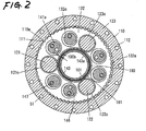
Fig. 2 is a sectional view taken along a line A-A ofFig. 1 . -
Fig.3 is a sectional view taken along a line B-B ofFig. 1 . -
Fig.4 is a side sectional view of an eccentrically oscillating speed reducer according to a second embodiment of the invention. -
Fig.5 is a sectional view taken along a line C-C ofFig.4 . -
Fig.6 is a side sectional view of an eccentrically oscillating speed reducer according to a third embodiment of the invention. - Embodiments of the invention will be explained in reference to the drawings as follows.
- First, a structure of an eccentrically oscillating speed reducer according to a first embodiment will be explained.
- As shown by
Fig.1 , ajoint 10 of an industrial robot includes anarm 20, anarm 30 turning relative to thearm 20,amotor 40 fixed to thearm 30 and generating a power for rotating thearm 30 relative to thearm 20, and an eccentrically oscillating speed reducer 100 fixed to thearm 20 and thearm 30 and constituting a power of thearm 30 relative to thearm 20 by the power generated by themotor 40 by reducing a speed thereof. - The eccentrically oscillating
speed reducer 100 includes acase 110 constituting a first member havinginner teeth 110a, acrankshaft 121 having aneccentric portion 121a, aneccentric portion 121b andouter teeth 121c, a crankshaft 122 (refer toFig. 2 ) having two eccentric portions, not illustrated, andouter teeth 122c (refer toFig.2 ) similar to thecrankshaft 121, a crankshaft 123 (refer toFig.2 ) having two eccentric portions, not illustrated andouter teeth 123c (refer toFig.2 ) similar to thecrankshaft 121, and anouter teeth gear 131 constituting an outer teeth member havingouter teeth 131a brought in mesh with theinner teeth 110a of thecase 110 and eccentrically moved by theeccentric portion 121a of thecrankshaft 121 or eccentric portions of thecrankshafts outer teeth gear 132 constituting an outer teeth member havingouter teeth 132a brought in mesh with theinner teeth 110a of thecase 110 and moved eccentrically by theeccentric portion 121b of thecrankshaft 121 or eccentric portions of thecrankshafts carrier 140 constituting a second member moved to rotate relative to thecase 110 by thecrankshafts Fig.3 ) attached to anoutput shaft 41 of themotor 40, anouter gear 152 attached to thecrankshaft 121 and brought in mesh with theinput gear 151,bearings carrier 140 relative to thecase 110, abearing 173 inserted to ahole 131b of theouter teeth gear 131 and rotatably supporting theeccentric portion 121b of thecrankshaft 121 relative to theouter teeth gear 131, abearing 174 inserted to ahole 132b of the outer teeth bearing 132 and supporting the eccentric portion of thecrankshaft 121 relative to theouter teeth gear 132, a bearing, not illustrated, inserted to a hole, not illustrated, of theouter teeth gear 131 similar to thehole 131b of theouter teeth gear 131 and rotatably supporting the eccentric portion of thecrankshaft 122 relative to theouter teeth gear 131 similar to thebearing 173, a bearing, not illustrated, inserted to a hole, not illustrated, of theouter teeth gear 132 similar to thehole 132b of theouter teeth gear 132 and rotatably supporting the eccentric portion of thecrankshaft 122 relative to theouter teeth gear 132 similar to thebearing 174, a bearing, not illustrated, inserted to a hole, not illustrated, of theouter teeth gear 131 similar to thehole 131b of theouter teeth gear 131 and rotatably supporting the eccentric portion of thecrankshaft 123 relative to theouter teeth gear 131 similar to thebearing 173, a bearing, notillustrated, inserted to a hole, not illustrated, of theouter teeth gear 132 similar to thehole 132b of theouter teeth gear 132 and rotatably supporting the eccentric portion of thecrankshaft 123 relative to theouter teeth gear 132 similar to thebearing 174,bearings crankshaft 121 at thecarrier 140, two bearings, not illustrated, rotatably supporting thecrankshaft 122 at thecarrier 140 similar to thebearings crankshaft 123 at thecarrier 140 similar to thebearings cylindrical gear 180 constituting a gear between crankshafts havingouter teeth 181 brought in mesh with theouter teeth crankshafts motor 40 inputted to thecrankshaft 121 to thecrankshafts oil seals case 110 and thecarrier 140, and thecarrier 140 is formed with athrough hole 101 substantially at a center thereof. - The
case 110 includes apin 111 for forming theinner teeth 110a, and apin support member 112 embedded with thepin 111. - The
crankshafts inner teeth 110a of thecase 110. - The
carrier 140 includes acircular plate 141 having acolumn portion 141a inserted to ahole 131c of theouter teeth gear 131 and ahole 132c of theouter teeth gear 132, acircular plate 142 arranged at a position of interposing theouter teeth gears circular plate 141, ahollow cylinder 143 constituting a gear inserting part both ends of which are fixed by thecircular plate 141 and thecircular plate 142 and which is inserted into thecylindrical gear 180, anO ring 144 for sealing a gap of thecircular plate 141 and thehollow cylinder 143, anO ring 145 for sealing a gap of thecircular plate 142 and the hollow cylinder143,apositioningpin146forpositioningthecircular plates bolt 147 for fastening thecircular plates column portions 141a, thepositioning pins 146, and thebolts 147 are arranged on a circumference centering on a center point of the gear of theinner teeth 110a of thecase 110. Further, thecarrier 140 is formed with agroove 140a containing theinput gear 151 and theouter gear 152. - The
cylindrical gear 180 is arranged between theouter teeth gear 131 and theouter teeth gear 132 and rotatably supported by being brought in mesh with theouter teeth crankshafts cylindrical gear 180 is rotatably supported by producing sliding friction at portions thereof in contact with theouter teeth gears - The
through hole 101 is constituted by ahole 141b of thecircular plate 141, ahole 142a of thecircular plate 142 and ahole 143a of thehollow cylinder 143. - Further, a
joint 10 includes abolt 51 for fixing thearm 20 and thecase 110, abolt 52 for fixing thearm 30 and themotor 40, abolt 53 for fixing thearm 30 and thecircular plate 141, ahole 30a of thearm 30 and awiring 60 passing the throughhole 101 of the eccentrically oscillatingspeed reducer 100. Further, respective pluralities of thebolts speed reducer 100. Further, a plurality of thebolts 52 are arranged on a circumference centering on an axis line of theoutput shaft 41 and themotor 40. - Further, engaging faces of the
arm 30 and themotor 40 and engaging faces of thearm 30 and thecircular plate 141 are respectively sealed by a seal agent or the like. - Next, operation of the
joint 10 will be explained. - When the
motor 40 generates a power, the power generated by themotor 40 is transmitted to thecrankshaft 121 by way of theinput gear 151 attached to theoutput shaft 41 of themotor 40 and theouter gear 152 attached to thecrankshaft 121 by reducing a speed thereof and is transmitted to thecylindrical gear 180 by way of theouter teeth 121c of thecrankshaft 121 and theouter teeth 181 of thecylindrical gear 180. Here, the power transmitted to thecylindrical gear 180 is transmitted to thecrankshaft 122 by way of theouter teeth 181 of thecylindrical gear 180 and theouter teeth 122c of thecrankshaft 122 and transmitted to thecrankshaft 123 by way of theouter teeth 181 of thecylindrical gear 180 and theouter teeth 123c of thecrankshaft 123. - Further, the power transmitted to the
crankshafts outer teeth gears eccentric portions crankshaft 121 and the eccentric portions of thecrankshafts carrier 140 by reducing a speed thereof by way of theouter teeth outer teeth gears inner teeth 110a of thecase 110. - Therefore, the
carrier 140 is rotated relative to thecase 110 and thearm 30 fixed to thecarrier 140 is rotated relative to thearm 20 fixed with thecase 110. - As explained above, according to the eccentrically oscillating
speed reducer 100, thecylindrical gear 180 is brought in mesh with theouter teeth crankshafts cylindrical gear 180, and therefore, a number of parts can be reduced more than that of the background art. - Further, according to the eccentrically oscillating
speed reducer 100, thecylindrical gear 180 is not supported by the rolling bearings as in the background art, and therefore, a diameter of the throughhole 101 can be made to be larger than that of the background art by an amount of dispensing with a portion supported by the rolling bearing which is not provided by thecylindrical gear 180. - Further, according to the eccentrically oscillating
speed reducer 100, thecylindrical gear 180 includes theouter teeth 181 brought in mesh with theouter teeth crankshafts cylindrical gear 180 is small-sized in comparison with a constitution in which the inter-crankshaft gear includes the inner teeth brought in mesh with theouter teeth crankshafts speed reducer 100, in comparison with a constitution in which the inter-crankshaft gear includes the inner teeth brought in mesh with theouter teeth crankshafts - Further, according to the eccentrically oscillating speed reducer 100, the
hollow cylinder 143 is inserted into thecylindrical gear 180 to separate a space at inside of the speed reducer and the throughhole 101 by thehollow cylinder 143, and therefore, even when a lubricant is sealed at the space at inside of the speed reducer, the lubricant sealed at the space at inside of the speed reducer can be prevented from leaking out to the throughhole 101. - Further, according to the eccentrically
oscillating speed reducer 100, thecylindrical gear 180 is arrangedbetween the outer teeth gear 131 and theouter teeth gear 132, thecylindrical gear 180 is brought in mesh with theouter teeth crankshafts bearings crankshaft 121 for supporting thecrankshaft 121 and substantially a middle portion between bearings installed at both ends of thecrankshafts crankshafts crankshafts outer teeth crankshafts cylindrical gear 180 are difficult to be inclined, and thecylindrical gear 180 and theouter teeth crankshafts oscillating speed reducer 100, uneven wear is difficult to be brought about at theouter teeth crankshafts cylindrical gear 180, and a reduction in service life of theouter teeth crankshafts cylindrical gear 180 can be prevented. - Further, in order to prevent a portion of the
cylindrical gear 180 from being brought into thehole 131d of the outer teeth gear 131 inserted with thehollow cylinder 143, it is necessary that a difference of an outer diameter of thecylindrical gear 180 and an outer diameter of thehollow cylinder 143 is always larger than adistance 100a between a face of forming thehole 131d of the outer teeth gear 131 and an outer peripheral face of thehollow cylinder 143. That is, in order to prevent a portion of thecylindrical gear 180 from being brought to thehole 131d of theouter teeth gear 131, it is necessary that thedifference 100b is larger than a maximum value of thedistance 100a. Here, the maximum value of thedistance 100a is set to be larger than twice as much as an eccentric amount of the outer teeth gear 131 relative to thecase 110 for preventing the outer teeth gear 131 and thehollow cylinder 143 from being brought into contact with each other in an eccentric movement of the outer teeth gear 131 relative to thecase 110. Although an explanation has been given of a relationship between the outer teeth gear 131 and thedifference 100b in the above-described, the same goes with a relationship between the outer teeth gear 132 and thedifference 100b. - First, a structure of an eccentrically oscillating speed reducer according to a second embodiment will be explained.
- Further, a constitution similar to the constitution of the eccentrically oscillating speed reducer 100 (refer to
Fig.1 ) according to the first embodiment in a constitution of the eccentrically oscillating speed reducer according to the embodiment is attached with notation the same as that of the constitution of the eccentricallyoscillating speed reducer 100 and a detailed explanation thereof will be omitted. - As shown by
Fig.4 andFig.5 , a constitution of an eccentricallyoscillating speed reducer 200 according to this embodiment is similar to a constitution in which the eccentricallyoscillating speed reducer 100 is provided with acylindrical gear 280 as a gear between crankshafts includinginner teeth 281 brought in mesh with theouter teeth crankshafts crankshaft 121 to thecrankshafts Fig.1 ). - The
cylindrical gear 280 is arranged between the outer teeth gear 131 and theouter teeth gear 132, and brought in mesh with theouter teeth crankshafts cylindrical gear 280 is rotatably supported by producing sliding friction at portions in contact with the outer teeth gears 131 and 132 by way of oil films. - In this embodiment, according to the eccentrically
oscillating speed reducer 200, thecylindrical gear 280 is brought into contact with apin 111 of thecase 110 at an outer periphery thereof, and therefore, even when outer teeth of the outer teeth gears 131 and 132 are separated temporarily from portions of the plurality of thepins 111 of thecase 110 when the outer teeth gears 131 and 132 are eccentrically moved relative to thecase 110 as in a case in which the tooth shape curves of the outer teeth gears 131 and 132 are constituted by curve portions present on the innermost sides of epitrochoidal curves laminated together by shifting phases thereof (refer toJP-B-58-42382 JP-A-2-261943 pins 111 can be prevented from being detached from thepin support member 112. - First, a structure of an eccentrically oscillating speed reducer according to a third embodiment will be explained.
- A constitution similar to the constitution of the eccentrically oscillating speed reducer 200 (refer to
Fig.4 ) according to the second embodiment in a constitution of the eccentrically oscillating speed reducer according to the embodiment is attached with notation the same as that of the constitution of the eccentricallyoscillating speed reducer 200 and a detailed explanation will be omitted. - As shown by
Fig.6 , a constitution of an eccentricallyoscillating speed reducer 300 according to the embodiment is similar to the constitution of the eccentricallyoscillating speed reducer 200 except that thecylindrical gear 280 is brought in mesh with theouter teeth bearing 172 in the axial direction, sliding friction is produced at portions of thecylindrical gear 280 in contact with the outer teeth gear 132 and thebearing 172 by way of oil films to be rotatably supported. - According to the eccentrically
oscillating speed reducer 300, the bearing 172 having a high hardness for rotatably supporting thecarrier 140 relative to thecase 110 is utilized also for supporting thecylindrical gear 280, and therefore, in comparison with a constitution in which thecylindrical gear 280 is supported by a member having a low hardness, reduction in service life by wearing a member can be prevented. - Further, although according to the eccentrically
oscillating speed reducer 300, thecylindrical gear 280 is constituted to produce sliding friction between thecylindrical gear 280 and aninner ring 172a of thebearing 172, thecylindrical gear 280 may be constituted to produce sliding friction between thecylindrical gear 280 and anouter ring 172b of thebearing 172. - Further, although the eccentrically
oscillating speed reducer 300 is provided with thecylindrical gear 280 having aninner teeth 281 brought in mesh with theouter teeth crankshafts crankshaft 121 to thecrankshafts carrier 140 relative to thecase 140 by sliding friction, a cylindrical gear having outer teeth brought in mesh with theouter teeth crankshafts cylindrical gear 280 as in the eccentrically oscillating speed reducer 100 (refer toFig.1 ) according to the first embodiment. - Further, although the inter-crankshaft gear of the invention is brought in mesh with the outer teeth provided at the crankshaft to be rotatably supported, by producing sliding friction at an outer periphery of the
hollow cylinder 143 or an inner periphery of thepin 111 by way of oil films, the inter-crankshaft gear may further be brought into a state of being supported rotatably. - As described above, the eccentrically oscillating speed reducer according to the invention achieves an effect of capable of reducing a number of parts more than that of the background art and is useful as an eccentrically oscillating speed reducer or the like used at a joint portion of an industrial machine of an industrial robot or the like.
Claims (8)
- An eccentrically oscillating speed reducer comprising:a first member having inner teeth;a plurality of crankshafts having outer teeth, an outer teeth member having outer teeth brought in mesh with the inner teeth of the first member and eccentrically moved by the crankshafts;a second member rotatably supporting the crankshafts and rotated to move relative to the first member by the crankshafts; andan inter-crankshaft gear brought in mesh with the outer teeth of the crankshafts to be rotatably supported and transmitting a power inputted to one crankshaft of the plurality of crankshafts to a remaining crankshaft.
- The eccentrically oscillating speed reducer according to Claim 1, wherein the inter-crankshaft gear includes outer teeth brought in mesh with the outer teeth of the crankshafts.
- The eccentrically oscillating speed reducer according to Claim 1, wherein the inter-crankshaft gear includes inner teeth brought in mesh with the outer teeth of the crankshafts.
- The eccentrically oscillating speed reducer according to Claim 1, wherein the inter-crankshaft gear frictionally slides relative to the outer teeth member by way of an oil film.
- The eccentrically oscillating speed reducer according to Claim 1, further comprising a bearing for rotatably supporting the second member relative to the first member, wherein an inter-crankshaft gear frictionally slides relative to the outer teeth member and the bearing by way of oil films.
- The eccentrically oscillating speed reducer according to Claim 1, wherein a through hole is formed substantially at a center of the second member;
wherein the through hole is arranged on an inner side of the inter-crankshaft gear. - The eccentrically oscillating speed reducer according to Claim 1, wherein the second member includes a gear inserting part inserted to the inter-crankshaft gear.
- The eccentrically oscillating speed reducer according to Claim 1, further comprising a plurality of the outer teeth members;
wherein the inter-crankshaft gear is arranged between the plurality of outer teeth members.
Applications Claiming Priority (2)
| Application Number | Priority Date | Filing Date | Title |
|---|---|---|---|
| JP2005265299 | 2005-09-13 | ||
| PCT/JP2006/318181 WO2007032400A1 (en) | 2005-09-13 | 2006-09-13 | Eccentrically rocking type reduction gear |
Publications (3)
| Publication Number | Publication Date |
|---|---|
| EP1925848A1 true EP1925848A1 (en) | 2008-05-28 |
| EP1925848A4 EP1925848A4 (en) | 2011-07-20 |
| EP1925848B1 EP1925848B1 (en) | 2013-06-05 |
Family
ID=37864991
Family Applications (1)
| Application Number | Title | Priority Date | Filing Date |
|---|---|---|---|
| EP06797931.0A Active EP1925848B1 (en) | 2005-09-13 | 2006-09-13 | Eccentrically rocking type reduction gear |
Country Status (6)
| Country | Link |
|---|---|
| US (1) | US7935017B2 (en) |
| EP (1) | EP1925848B1 (en) |
| JP (1) | JP4699470B2 (en) |
| KR (1) | KR101066234B1 (en) |
| CN (1) | CN101263319B (en) |
| WO (1) | WO2007032400A1 (en) |
Families Citing this family (33)
| Publication number | Priority date | Publication date | Assignee | Title |
|---|---|---|---|---|
| US9879760B2 (en) | 2002-11-25 | 2018-01-30 | Delbert Tesar | Rotary actuator with shortest force path configuration |
| JP4881646B2 (en) * | 2006-04-04 | 2012-02-22 | 住友重機械工業株式会社 | Decelerator |
| JP4851825B2 (en) * | 2006-03-29 | 2012-01-11 | 住友重機械工業株式会社 | Inscribed rocking mesh planetary gear reducer |
| DE102008026702B4 (en) | 2007-06-11 | 2021-04-22 | Sumitomo Heavy Industries, Ltd. | Joint drive device for a robot |
| JP2009024738A (en) * | 2007-07-17 | 2009-02-05 | Nabtesco Corp | Eccentric oscillating gear unit |
| WO2009017143A1 (en) * | 2007-07-31 | 2009-02-05 | Nabtesco Corporation | Gear device and rotation section structure adapted for industrial robot and using the gear device |
| JP2009041623A (en) | 2007-08-07 | 2009-02-26 | Sumitomo Heavy Ind Ltd | Oscillation inscribed planetary gear structure |
| JP2009041625A (en) * | 2007-08-07 | 2009-02-26 | Sumitomo Heavy Ind Ltd | Oscillation inscribed planetary gear structure |
| JP2009115274A (en) * | 2007-11-09 | 2009-05-28 | Nabtesco Corp | Eccentric oscillating gear device and joint structure of industrial robot equipped with the same |
| US8444520B2 (en) * | 2008-03-28 | 2013-05-21 | Nabtesco Corporation | Gear device |
| JP2010007830A (en) * | 2008-06-30 | 2010-01-14 | Nabtesco Corp | Gear device |
| JP5425668B2 (en) * | 2010-03-05 | 2014-02-26 | ナブテスコ株式会社 | Gear device |
| JP6029273B2 (en) * | 2011-11-10 | 2016-11-24 | ナブテスコ株式会社 | Gear transmission |
| CN103206517B (en) * | 2012-01-11 | 2017-04-26 | 株式会社捷太格特 | Speed Reduction Mechanism, And Motor Torque Transmission Device Including The Same |
| US10414271B2 (en) | 2013-03-01 | 2019-09-17 | Delbert Tesar | Multi-speed hub drive wheels |
| US9862263B2 (en) | 2013-03-01 | 2018-01-09 | Delbert Tesar | Multi-speed hub drive wheels |
| US9365105B2 (en) | 2013-10-11 | 2016-06-14 | Delbert Tesar | Gear train and clutch designs for multi-speed hub drives |
| US10422387B2 (en) | 2014-05-16 | 2019-09-24 | Delbert Tesar | Quick change interface for low complexity rotary actuator |
| US9657813B2 (en) | 2014-06-06 | 2017-05-23 | Delbert Tesar | Modified parallel eccentric rotary actuator |
| US9915319B2 (en) | 2014-09-29 | 2018-03-13 | Delbert Tesar | Compact parallel eccentric rotary actuator |
| CN105317933B (en) * | 2014-07-29 | 2016-11-09 | 江苏联合传动设备有限公司 | Single cycloidal gear speed reducer |
| US11014658B1 (en) | 2015-01-02 | 2021-05-25 | Delbert Tesar | Driveline architecture for rotorcraft featuring active response actuators |
| CN104696460B (en) * | 2015-01-15 | 2016-10-12 | 江苏联合传动设备有限公司 | Bearing decelerator |
| JP6522400B2 (en) * | 2015-04-15 | 2019-05-29 | ナブテスコ株式会社 | Reduction gear and gear used therefor |
| JP6629000B2 (en) * | 2015-07-31 | 2020-01-15 | ナブテスコ株式会社 | Eccentric oscillating gear device and its manufacturing method |
| JP6498569B2 (en) * | 2015-08-27 | 2019-04-10 | 住友重機械工業株式会社 | Eccentric rocking gear device |
| US10464413B2 (en) | 2016-06-24 | 2019-11-05 | Delbert Tesar | Electric multi-speed hub drive wheels |
| TWI609143B (en) | 2016-12-29 | 2017-12-21 | 財團法人工業技術研究院 | Eccentric oscillating speed reducer |
| CN108412967B (en) * | 2017-02-09 | 2024-09-27 | 国茂精密传动(常州)有限公司 | Eccentric swing type gear device |
| JP2021067316A (en) * | 2019-10-23 | 2021-04-30 | ナブテスコ株式会社 | Decelerator |
| JP7730299B2 (en) * | 2022-01-04 | 2025-08-27 | 住友重機械工業株式会社 | Eccentric oscillating gear device |
| KR102653722B1 (en) * | 2023-11-21 | 2024-04-02 | 에스아이이(주) | Motor housing cover of driving mechanism and drive mechanism using it |
| JP2025119912A (en) * | 2024-02-02 | 2025-08-15 | ナブテスコ株式会社 | Reducers and industrial machinery |
Family Cites Families (8)
| Publication number | Priority date | Publication date | Assignee | Title |
|---|---|---|---|---|
| US3217566A (en) * | 1963-08-20 | 1965-11-16 | Robert E Sanson | Gear transmission |
| JPH02261943A (en) | 1989-03-30 | 1990-10-24 | Teijin Seiki Co Ltd | planetary gear reducer |
| JP3659707B2 (en) | 1995-08-24 | 2005-06-15 | ナブテスコ株式会社 | Turning part structure for robots, etc. |
| JP3963587B2 (en) | 1998-09-02 | 2007-08-22 | 住友重機械工業株式会社 | Internal gear swing type intermeshing planetary gear unit |
| CN1293607A (en) * | 1999-01-28 | 2001-05-02 | 索尼公司 | Joint device for robot device and legged walking robot device |
| JP3703685B2 (en) * | 2000-05-15 | 2005-10-05 | ナブテスコ株式会社 | Eccentric oscillating speed reducer and joint of industrial machine having the same |
| JP3688230B2 (en) * | 2001-08-23 | 2005-08-24 | ナブテスコ株式会社 | Eccentric differential reducer |
| JP4267950B2 (en) * | 2003-03-28 | 2009-05-27 | 住友重機械工業株式会社 | Internal gear swing type intermeshing planetary gear unit |
-
2006
- 2006-09-13 CN CN2006800336035A patent/CN101263319B/en active Active
- 2006-09-13 US US12/066,400 patent/US7935017B2/en active Active
- 2006-09-13 JP JP2007535515A patent/JP4699470B2/en active Active
- 2006-09-13 KR KR1020087006202A patent/KR101066234B1/en active Active
- 2006-09-13 WO PCT/JP2006/318181 patent/WO2007032400A1/en not_active Ceased
- 2006-09-13 EP EP06797931.0A patent/EP1925848B1/en active Active
Also Published As
| Publication number | Publication date |
|---|---|
| CN101263319A (en) | 2008-09-10 |
| JP4699470B2 (en) | 2011-06-08 |
| KR20080043839A (en) | 2008-05-19 |
| WO2007032400A1 (en) | 2007-03-22 |
| EP1925848A4 (en) | 2011-07-20 |
| JPWO2007032400A1 (en) | 2009-03-19 |
| KR101066234B1 (en) | 2011-09-21 |
| EP1925848B1 (en) | 2013-06-05 |
| CN101263319B (en) | 2013-07-10 |
| US20100261567A1 (en) | 2010-10-14 |
| US7935017B2 (en) | 2011-05-03 |
Similar Documents
| Publication | Publication Date | Title |
|---|---|---|
| EP1925848B1 (en) | Eccentrically rocking type reduction gear | |
| US7901317B2 (en) | Reduction gear | |
| EP1918611A1 (en) | Center crank type eccentrically rocking reduction gear | |
| KR102381750B1 (en) | Reducer device | |
| EP2381130A2 (en) | Speed change gear | |
| EP2273140A1 (en) | Device with seals | |
| EP2592302A1 (en) | Deceleration device | |
| KR20120099748A (en) | Swinging internal engagement type planetary gear device | |
| US8343003B2 (en) | Joint driving apparatus for robot | |
| KR20150099387A (en) | Flexible engagement gear device | |
| JP6059643B2 (en) | Reduction gear | |
| KR101715978B1 (en) | Gear transmission | |
| KR20190106742A (en) | Gear unit | |
| JP5832959B2 (en) | Planetary gear set | |
| EP3812615B1 (en) | Speed reducer | |
| US11873891B2 (en) | Planetary gearbox, assembly method thereof, associated robot joint and robot | |
| EP3647616A1 (en) | Bearing and speed reducer | |
| CN111043251A (en) | Eccentric oscillating type reduction gear | |
| CN111720497B (en) | Cycloidal speed reducer, method for manufacturing cycloidal speed reducer, and motor unit | |
| JP2021028500A (en) | Differential speed reducer | |
| CN211231515U (en) | Eccentric transmission mechanism of speed reducer | |
| EP4345329A1 (en) | Bearing, strain wave gear device, and industrial robot | |
| JP2005344885A (en) | Planetary roller type speed reducer and speed reducer series | |
| JP2010043679A (en) | Reduction gear and method for fixing planetary gear for the same | |
| JP2010151231A (en) | Oil seal and turning device |
Legal Events
| Date | Code | Title | Description |
|---|---|---|---|
| PUAI | Public reference made under article 153(3) epc to a published international application that has entered the european phase |
Free format text: ORIGINAL CODE: 0009012 |
|
| 17P | Request for examination filed |
Effective date: 20080310 |
|
| AK | Designated contracting states |
Kind code of ref document: A1 Designated state(s): AT BE BG CH CY CZ DE DK EE ES FI FR GB GR HU IE IS IT LI LT LU LV MC NL PL PT RO SE SI SK TR |
|
| A4 | Supplementary search report drawn up and despatched |
Effective date: 20110621 |
|
| 17Q | First examination report despatched |
Effective date: 20120207 |
|
| DAX | Request for extension of the european patent (deleted) | ||
| GRAP | Despatch of communication of intention to grant a patent |
Free format text: ORIGINAL CODE: EPIDOSNIGR1 |
|
| RIN1 | Information on inventor provided before grant (corrected) |
Inventor name: HIROSE, JUN C/O TSU PLANT NABTESCO CORPORATION Inventor name: KAWASHIMA, KOJI C/O TSU PLANT NABTESCO CORPORATION Inventor name: KURITA, MASAKAZU C/O TSU PLANT NABTESCO CORPORATIO |
|
| GRAS | Grant fee paid |
Free format text: ORIGINAL CODE: EPIDOSNIGR3 |
|
| GRAA | (expected) grant |
Free format text: ORIGINAL CODE: 0009210 |
|
| AK | Designated contracting states |
Kind code of ref document: B1 Designated state(s): AT BE BG CH CY CZ DE DK EE ES FI FR GB GR HU IE IS IT LI LT LU LV MC NL PL PT RO SE SI SK TR |
|
| REG | Reference to a national code |
Ref country code: GB Ref legal event code: FG4D |
|
| REG | Reference to a national code |
Ref country code: CH Ref legal event code: EP |
|
| REG | Reference to a national code |
Ref country code: AT Ref legal event code: REF Ref document number: 615851 Country of ref document: AT Kind code of ref document: T Effective date: 20130615 |
|
| REG | Reference to a national code |
Ref country code: IE Ref legal event code: FG4D |
|
| REG | Reference to a national code |
Ref country code: DE Ref legal event code: R096 Ref document number: 602006036689 Country of ref document: DE Effective date: 20130801 |
|
| REG | Reference to a national code |
Ref country code: AT Ref legal event code: MK05 Ref document number: 615851 Country of ref document: AT Kind code of ref document: T Effective date: 20130605 |
|
| PG25 | Lapsed in a contracting state [announced via postgrant information from national office to epo] |
Ref country code: FI Free format text: LAPSE BECAUSE OF FAILURE TO SUBMIT A TRANSLATION OF THE DESCRIPTION OR TO PAY THE FEE WITHIN THE PRESCRIBED TIME-LIMIT Effective date: 20130605 Ref country code: GR Free format text: LAPSE BECAUSE OF FAILURE TO SUBMIT A TRANSLATION OF THE DESCRIPTION OR TO PAY THE FEE WITHIN THE PRESCRIBED TIME-LIMIT Effective date: 20130906 Ref country code: LT Free format text: LAPSE BECAUSE OF FAILURE TO SUBMIT A TRANSLATION OF THE DESCRIPTION OR TO PAY THE FEE WITHIN THE PRESCRIBED TIME-LIMIT Effective date: 20130605 Ref country code: AT Free format text: LAPSE BECAUSE OF FAILURE TO SUBMIT A TRANSLATION OF THE DESCRIPTION OR TO PAY THE FEE WITHIN THE PRESCRIBED TIME-LIMIT Effective date: 20130605 Ref country code: SI Free format text: LAPSE BECAUSE OF FAILURE TO SUBMIT A TRANSLATION OF THE DESCRIPTION OR TO PAY THE FEE WITHIN THE PRESCRIBED TIME-LIMIT Effective date: 20130605 Ref country code: SE Free format text: LAPSE BECAUSE OF FAILURE TO SUBMIT A TRANSLATION OF THE DESCRIPTION OR TO PAY THE FEE WITHIN THE PRESCRIBED TIME-LIMIT Effective date: 20130605 Ref country code: ES Free format text: LAPSE BECAUSE OF FAILURE TO SUBMIT A TRANSLATION OF THE DESCRIPTION OR TO PAY THE FEE WITHIN THE PRESCRIBED TIME-LIMIT Effective date: 20130916 |
|
| REG | Reference to a national code |
Ref country code: NL Ref legal event code: VDEP Effective date: 20130605 |
|
| REG | Reference to a national code |
Ref country code: LT Ref legal event code: MG4D |
|
| PG25 | Lapsed in a contracting state [announced via postgrant information from national office to epo] |
Ref country code: PL Free format text: LAPSE BECAUSE OF FAILURE TO SUBMIT A TRANSLATION OF THE DESCRIPTION OR TO PAY THE FEE WITHIN THE PRESCRIBED TIME-LIMIT Effective date: 20130605 Ref country code: BG Free format text: LAPSE BECAUSE OF FAILURE TO SUBMIT A TRANSLATION OF THE DESCRIPTION OR TO PAY THE FEE WITHIN THE PRESCRIBED TIME-LIMIT Effective date: 20130905 |
|
| PG25 | Lapsed in a contracting state [announced via postgrant information from national office to epo] |
Ref country code: LV Free format text: LAPSE BECAUSE OF FAILURE TO SUBMIT A TRANSLATION OF THE DESCRIPTION OR TO PAY THE FEE WITHIN THE PRESCRIBED TIME-LIMIT Effective date: 20130605 |
|
| PG25 | Lapsed in a contracting state [announced via postgrant information from national office to epo] |
Ref country code: SK Free format text: LAPSE BECAUSE OF FAILURE TO SUBMIT A TRANSLATION OF THE DESCRIPTION OR TO PAY THE FEE WITHIN THE PRESCRIBED TIME-LIMIT Effective date: 20130605 Ref country code: EE Free format text: LAPSE BECAUSE OF FAILURE TO SUBMIT A TRANSLATION OF THE DESCRIPTION OR TO PAY THE FEE WITHIN THE PRESCRIBED TIME-LIMIT Effective date: 20130605 Ref country code: BE Free format text: LAPSE BECAUSE OF FAILURE TO SUBMIT A TRANSLATION OF THE DESCRIPTION OR TO PAY THE FEE WITHIN THE PRESCRIBED TIME-LIMIT Effective date: 20130605 Ref country code: IS Free format text: LAPSE BECAUSE OF FAILURE TO SUBMIT A TRANSLATION OF THE DESCRIPTION OR TO PAY THE FEE WITHIN THE PRESCRIBED TIME-LIMIT Effective date: 20131005 Ref country code: PT Free format text: LAPSE BECAUSE OF FAILURE TO SUBMIT A TRANSLATION OF THE DESCRIPTION OR TO PAY THE FEE WITHIN THE PRESCRIBED TIME-LIMIT Effective date: 20131007 Ref country code: CZ Free format text: LAPSE BECAUSE OF FAILURE TO SUBMIT A TRANSLATION OF THE DESCRIPTION OR TO PAY THE FEE WITHIN THE PRESCRIBED TIME-LIMIT Effective date: 20130605 |
|
| PG25 | Lapsed in a contracting state [announced via postgrant information from national office to epo] |
Ref country code: NL Free format text: LAPSE BECAUSE OF FAILURE TO SUBMIT A TRANSLATION OF THE DESCRIPTION OR TO PAY THE FEE WITHIN THE PRESCRIBED TIME-LIMIT Effective date: 20130605 Ref country code: RO Free format text: LAPSE BECAUSE OF FAILURE TO SUBMIT A TRANSLATION OF THE DESCRIPTION OR TO PAY THE FEE WITHIN THE PRESCRIBED TIME-LIMIT Effective date: 20130605 |
|
| PLBE | No opposition filed within time limit |
Free format text: ORIGINAL CODE: 0009261 |
|
| STAA | Information on the status of an ep patent application or granted ep patent |
Free format text: STATUS: NO OPPOSITION FILED WITHIN TIME LIMIT |
|
| PG25 | Lapsed in a contracting state [announced via postgrant information from national office to epo] |
Ref country code: MC Free format text: LAPSE BECAUSE OF FAILURE TO SUBMIT A TRANSLATION OF THE DESCRIPTION OR TO PAY THE FEE WITHIN THE PRESCRIBED TIME-LIMIT Effective date: 20130605 Ref country code: DK Free format text: LAPSE BECAUSE OF FAILURE TO SUBMIT A TRANSLATION OF THE DESCRIPTION OR TO PAY THE FEE WITHIN THE PRESCRIBED TIME-LIMIT Effective date: 20130605 |
|
| REG | Reference to a national code |
Ref country code: CH Ref legal event code: PL |
|
| 26N | No opposition filed |
Effective date: 20140306 |
|
| GBPC | Gb: european patent ceased through non-payment of renewal fee |
Effective date: 20130913 |
|
| PG25 | Lapsed in a contracting state [announced via postgrant information from national office to epo] |
Ref country code: IT Free format text: LAPSE BECAUSE OF FAILURE TO SUBMIT A TRANSLATION OF THE DESCRIPTION OR TO PAY THE FEE WITHIN THE PRESCRIBED TIME-LIMIT Effective date: 20130605 |
|
| REG | Reference to a national code |
Ref country code: DE Ref legal event code: R097 Ref document number: 602006036689 Country of ref document: DE Effective date: 20140306 |
|
| REG | Reference to a national code |
Ref country code: FR Ref legal event code: ST Effective date: 20140530 |
|
| REG | Reference to a national code |
Ref country code: IE Ref legal event code: MM4A |
|
| PG25 | Lapsed in a contracting state [announced via postgrant information from national office to epo] |
Ref country code: LI Free format text: LAPSE BECAUSE OF NON-PAYMENT OF DUE FEES Effective date: 20130930 Ref country code: IE Free format text: LAPSE BECAUSE OF NON-PAYMENT OF DUE FEES Effective date: 20130913 Ref country code: CH Free format text: LAPSE BECAUSE OF NON-PAYMENT OF DUE FEES Effective date: 20130930 Ref country code: GB Free format text: LAPSE BECAUSE OF NON-PAYMENT OF DUE FEES Effective date: 20130913 |
|
| PG25 | Lapsed in a contracting state [announced via postgrant information from national office to epo] |
Ref country code: FR Free format text: LAPSE BECAUSE OF NON-PAYMENT OF DUE FEES Effective date: 20130930 |
|
| PG25 | Lapsed in a contracting state [announced via postgrant information from national office to epo] |
Ref country code: CY Free format text: LAPSE BECAUSE OF FAILURE TO SUBMIT A TRANSLATION OF THE DESCRIPTION OR TO PAY THE FEE WITHIN THE PRESCRIBED TIME-LIMIT Effective date: 20130605 Ref country code: TR Free format text: LAPSE BECAUSE OF FAILURE TO SUBMIT A TRANSLATION OF THE DESCRIPTION OR TO PAY THE FEE WITHIN THE PRESCRIBED TIME-LIMIT Effective date: 20130605 |
|
| PG25 | Lapsed in a contracting state [announced via postgrant information from national office to epo] |
Ref country code: LU Free format text: LAPSE BECAUSE OF NON-PAYMENT OF DUE FEES Effective date: 20130913 Ref country code: HU Free format text: LAPSE BECAUSE OF FAILURE TO SUBMIT A TRANSLATION OF THE DESCRIPTION OR TO PAY THE FEE WITHIN THE PRESCRIBED TIME-LIMIT; INVALID AB INITIO Effective date: 20060913 |
|
| P01 | Opt-out of the competence of the unified patent court (upc) registered |
Effective date: 20230615 |
|
| PGFP | Annual fee paid to national office [announced via postgrant information from national office to epo] |
Ref country code: DE Payment date: 20250919 Year of fee payment: 20 |