EP1925838A1 - Boot for constant velocity universal joint - Google Patents
Boot for constant velocity universal joint Download PDFInfo
- Publication number
- EP1925838A1 EP1925838A1 EP06797789A EP06797789A EP1925838A1 EP 1925838 A1 EP1925838 A1 EP 1925838A1 EP 06797789 A EP06797789 A EP 06797789A EP 06797789 A EP06797789 A EP 06797789A EP 1925838 A1 EP1925838 A1 EP 1925838A1
- Authority
- EP
- European Patent Office
- Prior art keywords
- peak
- valley
- section
- boot
- diameter section
- Prior art date
- Legal status (The legal status is an assumption and is not a legal conclusion. Google has not performed a legal analysis and makes no representation as to the accuracy of the status listed.)
- Granted
Links
Images


Classifications
-
- F—MECHANICAL ENGINEERING; LIGHTING; HEATING; WEAPONS; BLASTING
- F16—ENGINEERING ELEMENTS AND UNITS; GENERAL MEASURES FOR PRODUCING AND MAINTAINING EFFECTIVE FUNCTIONING OF MACHINES OR INSTALLATIONS; THERMAL INSULATION IN GENERAL
- F16D—COUPLINGS FOR TRANSMITTING ROTATION; CLUTCHES; BRAKES
- F16D3/00—Yielding couplings, i.e. with means permitting movement between the connected parts during the drive
- F16D3/84—Shrouds, e.g. casings, covers; Sealing means specially adapted therefor
- F16D3/843—Shrouds, e.g. casings, covers; Sealing means specially adapted therefor enclosed covers
- F16D3/845—Shrouds, e.g. casings, covers; Sealing means specially adapted therefor enclosed covers allowing relative movement of joint parts due to the flexing of the cover
-
- F—MECHANICAL ENGINEERING; LIGHTING; HEATING; WEAPONS; BLASTING
- F16—ENGINEERING ELEMENTS AND UNITS; GENERAL MEASURES FOR PRODUCING AND MAINTAINING EFFECTIVE FUNCTIONING OF MACHINES OR INSTALLATIONS; THERMAL INSULATION IN GENERAL
- F16D—COUPLINGS FOR TRANSMITTING ROTATION; CLUTCHES; BRAKES
- F16D3/00—Yielding couplings, i.e. with means permitting movement between the connected parts during the drive
- F16D3/16—Universal joints in which flexibility is produced by means of pivots or sliding or rolling connecting parts
- F16D3/20—Universal joints in which flexibility is produced by means of pivots or sliding or rolling connecting parts one coupling part entering a sleeve of the other coupling part and connected thereto by sliding or rolling members
- F16D3/22—Universal joints in which flexibility is produced by means of pivots or sliding or rolling connecting parts one coupling part entering a sleeve of the other coupling part and connected thereto by sliding or rolling members the rolling members being balls, rollers, or the like, guided in grooves or sockets in both coupling parts
- F16D3/223—Universal joints in which flexibility is produced by means of pivots or sliding or rolling connecting parts one coupling part entering a sleeve of the other coupling part and connected thereto by sliding or rolling members the rolling members being balls, rollers, or the like, guided in grooves or sockets in both coupling parts the rolling members being guided in grooves in both coupling parts
- F16D3/2237—Universal joints in which flexibility is produced by means of pivots or sliding or rolling connecting parts one coupling part entering a sleeve of the other coupling part and connected thereto by sliding or rolling members the rolling members being balls, rollers, or the like, guided in grooves or sockets in both coupling parts the rolling members being guided in grooves in both coupling parts where the grooves are composed of radii and adjoining straight lines, i.e. undercut free [UF] type joints
-
- F—MECHANICAL ENGINEERING; LIGHTING; HEATING; WEAPONS; BLASTING
- F16—ENGINEERING ELEMENTS AND UNITS; GENERAL MEASURES FOR PRODUCING AND MAINTAINING EFFECTIVE FUNCTIONING OF MACHINES OR INSTALLATIONS; THERMAL INSULATION IN GENERAL
- F16J—PISTONS; CYLINDERS; SEALINGS
- F16J3/00—Diaphragms; Bellows; Bellows pistons
- F16J3/04—Bellows
- F16J3/041—Non-metallic bellows
-
- F—MECHANICAL ENGINEERING; LIGHTING; HEATING; WEAPONS; BLASTING
- F16—ENGINEERING ELEMENTS AND UNITS; GENERAL MEASURES FOR PRODUCING AND MAINTAINING EFFECTIVE FUNCTIONING OF MACHINES OR INSTALLATIONS; THERMAL INSULATION IN GENERAL
- F16D—COUPLINGS FOR TRANSMITTING ROTATION; CLUTCHES; BRAKES
- F16D3/00—Yielding couplings, i.e. with means permitting movement between the connected parts during the drive
- F16D3/16—Universal joints in which flexibility is produced by means of pivots or sliding or rolling connecting parts
- F16D3/20—Universal joints in which flexibility is produced by means of pivots or sliding or rolling connecting parts one coupling part entering a sleeve of the other coupling part and connected thereto by sliding or rolling members
- F16D3/22—Universal joints in which flexibility is produced by means of pivots or sliding or rolling connecting parts one coupling part entering a sleeve of the other coupling part and connected thereto by sliding or rolling members the rolling members being balls, rollers, or the like, guided in grooves or sockets in both coupling parts
- F16D3/223—Universal joints in which flexibility is produced by means of pivots or sliding or rolling connecting parts one coupling part entering a sleeve of the other coupling part and connected thereto by sliding or rolling members the rolling members being balls, rollers, or the like, guided in grooves or sockets in both coupling parts the rolling members being guided in grooves in both coupling parts
- F16D2003/22316—Means for fastening or attaching the bellows or gaiters
Definitions
- the present invention relates to a boot for a constant velocity universal joint.
- the present invention relates to a boot for a constant velocity universal joint used for power transmission in automobiles and various industrial machineries.
- a bellows-like boot is attached to a constant velocity universal joint used for power transmission in automobiles and various industrial machineries.
- the bellows-like boot aims to prevent ingress of foreign objects, such as dust, into an interior of the joint and leakage of grease enclosed in the interior of the joint.
- a resin boot made from a thermoplastic elastomer is recently being used.
- this type of boot includes a large diameter section 102, a small diameter section 105, and a bellows section 108.
- the large diameter section 102 is fixed onto an outer ring 101 of a constant velocity universal joint 100.
- the small diameter section 105 is fixed onto a shaft 104 that extends from an inner ring 103.
- the bellows section 108 is provided between the large diameter section 102 and the small diameter section 105. Alternating valleys 106 and peaks 107 are formed in the bellows section 108.
- the large diameter section 102 and the small diameter section 105 are respectively fixed by a boot band 109 being fitted onto the large diameter section 102 and the small diameter section 105.
- a valley 106 closest to the large diameter section 102 is not in contact with the outer ring 101.
- the valley 106 closest to the large diameter section 102 may become caught between an opening end section and the shaft 104 at an opening section 101a of the outer ring 101 and become damaged.
- the boot cannot function as a boot, thereby requiring replacement or the like. Therefore, in a conventional boot such as that shown in Fig. 3 , a diameter of the valley 106 is required to be large to prevent the valley 106 from becoming caught between the opening end section and the shaft 104.
- a cylindrical section is provided between the large diameter section and the bellows section (Patent Document 1).
- a cylindrical section 111 having a larger inner diameter dimension than an outer diameter dimension of the outer ring 101 is provided between the large diameter section 102 and the bellows section 108.
- a thickness of the cylindrical section 111 is thicker than a thickness of the bellows section 108.
- a boot in which the diameter of the cylindrical section 111 is successively widened from the large diameter section 102 side towards the small diameter section 105 side.
- the boot flexes in an outer radial direction, as indicated by a phantom line, thereby preventing the valley 106 from becoming caught.
- Patent Document 2 and Patent Document 3 There is also a boot in which various boot thicknesses are set to prevent friction caused by rubbing within the bellows section in the bent joint state, thereby achieving enhancement in abrasion resistance.
- Patent Document 4 There is also a boot that bends in adherence to the bending of the joint, thereby preventing damage and achieving an enhancement in fatigability from flexing.
- Patent Document 1 Japanese Utility Model Application Publication No. 2525619
- Patent Document 2 Japanese Utility Model Laid-Open Publication No. Heisei 7-10561
- Patent Document 3 Japanese Utility Model Laid-Open Publication No. Heisei 6-82463
- Patent Document 4 Japanese Patent Laid-open Publication No.
- Patent Document 5 Japanese Patent Laid-open Publication No. Heisei 6-129536
- Patent Document 6 Japanese Patent Laid-open Publication No. Heisei 8-135675
- Patent Document 7 Japanese Utility Model Laid-Open Publication No. Heisei 7-38758
- the peak 107 is required to be designed to be higher to ensure bellows length (bellows film length). Therefore, a maximum outer diameter of the bellows section increases, thereby causing a spatial disadvantage.
- an axial direction length of the cylindrical section 111 is required to be relatively long. Therefore, an axial direction length of the entire boot increases. As a result, the numbers and disposal pitches of valleys 106 and peaks 107 in the bellows section 108 may be restricted, and flexibility and stretchability may deteriorate.
- Patent Document 2 In the boots described in Patent Document 2, Patent Document 3 and the like, abrasion resistance is enhanced. In Patent Document 4 to Patent Document 7 and the like, fatigability from flexing is enhanced, thereby extending life of the boot. Therefore, a boot such as those described in these Patent Documents and the like cannot prevent the bellows section from becoming caught in the outer ring opening section.
- the present invention provides a boot for a constant velocity universal joint that is compact in shape and can prevent a bellows section from becoming caught in an outer ring opening section.
- a boot for a constant velocity universal joint of the present invention includes a large diameter section that is attached to an opening end section of an outer joint component of a constant velocity universal joint, a small diameter section that is attached to a shaft connected to an inner joint component of the constant velocity universal joint, and a bellows section that is provided between the large diameter section and the small diameter section and has peaks and valleys alternately disposed in an axial direction.
- a peak is provided adjacent to the large diameter section and to the small diameter section.
- a peak and valley of an axial direction center section as reference, thicknesses of peaks and valleys to the small diameter section side of the reference peak and valley are thinner than reference thickness of the reference peak and valley and thicknesses of peaks and valleys to the large diameter section side of the reference peak and valley are thicker than the reference thickness of the reference peak and valley.
- the thickness of the peak adjacent to the large diameter section is the reference thickness.
- the peak is provided adjacent to the large diameter section and to the small diameter section.
- the thicknesses of the peaks and valleys to the small diameter section side of the reference peak and valley are thinner than the reference thickness of the reference peak and valley, and the thicknesses of peaks and valleys to the large diameter section side of the reference peak and valley are thicker than the reference thickness of the reference peak and valley.
- the thickness of the peak adjacent to the large diameter section is the reference thickness.
- a valley closest to the large diameter section can be displaced such as to prevent becoming caught between an opening end section of the outer ring and the shaft.
- the thicknesses of the peaks thicker than the reference thickness are preferably thicker than the thicknesses of the valleys thicker than the reference thickness.
- the bellows section has seven peaks and six valleys, and third peak and valley from the small diameter section are the reference.
- the thicknesses of the peaks and valleys can be increased or decreased within a range of 85% to 115%.
- a difference between the thicknesses m and r of two arbitrarily selected peaks 16 and valleys 17 is preferably kept constant.
- thermoplastic elastomer of an ester series, olefin series, urethane series, amide series, styrene series, and the like can be used as a boot material.
- the present invention can prevent the valley of the bellows section from becoming caught between the opening end section of the opening section of the outer ring and the shaft. As a result, damage to the bellows section caused by jamming on the joint side can be prevented.
- the boot can function as a boot for a long period of time. Because jamming is prevented, the outer diameter dimension is not required to be large. An interference range with peripheral devices can be reduced. Freedom in boot design increases. A design can be made in which the diameter of the valley closest to the large diameter section (position closest to the large diameter section) is made smaller than (lowered from) a track section diameter of the outer ring and a bellows length (bellows film length) is secured. A design having overall compactness in the radial direction and the axial direction can be made.
- the thicknesses of the peaks and valleys can be increased or decreased within the range of 85% to 115%. Therefore, high dimensional accuracy is not really required, and simplification of manufacturing can be achieved.
- the constant velocity universal joint boot 1 has superior strength and is advantageous in terms of abrasion resistance.
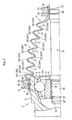
- a constant velocity universal joint boot 1 is attached to a constant velocity universal joint 2, as shown in Fig. 1 .
- the constant velocity universal joint 2 includes an outer joint member (outer ring) 4, an inner joint member (inner ring) 6, a plurality of balls 7, a holder 8, and the like.
- a plurality of guiding grooves (track grooves) 3 are formed on an inner circumferential surface of the outer ring 4 in an axial direction.
- a plurality of guiding grooves (track grooves) 5 are formed on an outer circumferential surface of the inner ring 6.
- the balls 7 are placed on ball tracks formed through coordination between the guiding grooves 3 of the outer ring 4 and the guiding grooves 5 of the inner ring 6.
- the holder 8 has pockets 8a for storing the balls 7.
- a shaft 10 is connected to an inner circumference of the inner ring 6, via a torque transmitting means, such as serration or a spline.
- a spline forming section 25 on which a spline 24 is formed is provided on an end section of the shaft 10.
- the spline forming section 25 being inserted into a center hole of the inner ring 6, the spline 24 of the shaft 10 and a spline 26 formed on an inner circumferential surface of the inner ring 6 are engaged.
- a stopper ring groove 27 is formed on the spline forming section 25 within an axial direction range of the spline 24.
- a stopper ring 28 is engaged with the stopper ring groove 27, forming a dislocation stopping mechanism.
- the constant velocity universal joint 2 is merely required to be that to which the constant velocity universal joint boot 1 can be attached. Therefore, various kinds of constant velocity universal joints can be used, for example, fixed constant velocity universal joints such as a Rzeppa-type or a Birfield-type, or slide-type constant velocity universal joints such as a double-offset-type, a tri-port-type, or a cross-groove-type.
- fixed constant velocity universal joints such as a Rzeppa-type or a Birfield-type
- slide-type constant velocity universal joints such as a double-offset-type, a tri-port-type, or a cross-groove-type.
- the constant velocity universal joint boot 1 (sometimes referred to, hereinafter, as simply boot 1) is formed by, for example, a thermoplastic elastomer of an ester series, olefin series, urethane series, amide series, styrene series, and the like.
- the thermoplastic elastomer has characteristics that are between plastic and rubber. While the thermoplastic elastomer is a rubber elastic body, the thermoplastic elastomer can be processed by an ordinary thermoplastic resin molding machine.
- the thermoplastic elastomer has advantages such as having self-reinforcement properties, having sufficient strength without use of reinforcing materials, not requiring a vulcanizing procedure during ordinary rubber molding, and furthermore, achieving simplified composition.
- the constant velocity universal joint boot 1 is formed from a cylindrical body and includes a large diameter section 11, a small diameter section 12, and a bellows section 13.
- the large diameter section 11 is fixed onto the outer ring 4.
- the small diameter section 12 is fixed onto the shaft 10 extending from the inner ring 6.
- the bellows section 13 is provided between the large diameter section 11 and the small diameter section 12.
- a plurality of valleys 15 and peaks 16 are alternately disposed in the bellows section 13 along an axial direction. Therefore, the boot 1 is provided with flexibility and stretchability in the axial direction.
- a valley 15 and a peak 16 are connected by a sloping section 17.
- a ring-shaped engaging groove 20 is formed in a circumferential direction on an outer circumferential surface on an opening side of the outer ring 4.
- the large diameter section 11 of the boot 1 is fitted outside of the opening side of the outer ring 4 such as to cover the engaging groove 20.
- a boot band 21 is fitted and attached to a fitting groove 18 formed on an outer circumferential surface of the large diameter section 11, thereby fixing the large diameter section 11 onto the outer ring 4.
- a boot attaching section 22 is provided in a position on the shaft 10 that projects from the outer ring 4 by a predetermined amount.
- the boot attaching section 22 has a ring-shaped engaging groove 23 along the circumferential direction.
- the small diameter section 12 of the boot 1 is fitted outside of the boot attaching section 22 such as to cover the engaging groove 23.
- the boot band 21 is fitted and attached to a fitting groove 19 formed on an outer circumferential surface of the small diameter section 12, thereby fixing the small diameter section 12 onto the shaft 10.
- the bellows section 13 of the boot 1 has seven peaks 16 and six valleys 15. Therefore, the peak 16 is provided adjacent to the large diameter section 11 and to the small diameter section 12.
- the peaks 16 from the small diameter section 12 towards the large diameter section 11 are sequentially referred to as a first peak 16a, a second peak 16b, a third peak 16c, a fourth peak 16d, a fifth peak 16e, a sixth peak 16f, and a seventh peak 16g.
- the valleys 15 are sequentially referred to as a first valley 15a, a second valley 15b, a third valley 15c, a fourth valley 15d, a fifth valley 15e, and a sixth valley 15f.
- thicknesses m and r (see Fig. 2 ) of the peaks and valleys 16 and 15 to the small diameter section 12 side of the reference peak and valley 16 and 15 are thinner than a reference thickness of the reference peak and valley 16 and 15. Thicknesses of the peaks and valleys 16 and 15 to the large diameter section 11 side of the reference peak and valley 16 and 15 are thicker than the reference thickness. Furthermore, a thickness m of the peak 16 (seventh peak 16g) adjacent to the large diameter section 11 is the reference thickness.
- each peak 16 and the thickness r of each valley 15 are set as shown in a following Table 1.
- A indicates the reference thickness.
- A can be arbitrarily set depending on a boot material being used and the like.
- a thickness m3 of the third peak 16c and a thickness r3 of the third valley 15c are the reference thickness.
- Thickness r1 of the first valley 15a and thickness r2 of the second valley 15b are each about 0.15 millimeters thinner than the reference thickness A.
- Thickness r4 of the fourth valley 15d, thickness r5 of the fifth valley 15e, and thickness r6 of the sixth valley 15f are each about 0.1 millimeters larger than the reference thickness A.
- the peak 16 is provided adjacent to the large diameter section 11 and to the small diameter section 12.
- the thicknesses of the peaks and valleys 16 and 15 to the small diameter section 12 side of the reference peak and valley 16 and 15 are thinner than the reference thickness of the reference peak and valley 16 and 15.
- the thicknesses of the peaks and valleys 16 and 15 to the large diameter section 11 side of the reference peak and valley 16 and 15 are thicker than the reference thickness.
- the thickness of the peak adjacent to the large diameter section is the reference thickness.
- the valley 15 closest to the large diameter section 11 can be displaced such as to prevent becoming caught between an opening end section 4a of the outer ring 4 and the shaft 10.
- the valley 15 of the bellows section 13 can be prevented from becoming caught between the opening end section 4a of the outer ring 4 and the shaft 10 in the bent joint state. Therefore, damage to the bellows section 13 caused by jamming on the joint side can be prevented.
- the boot can function as a boot for a long period of time. Because jamming is prevented, the outer diameter dimension is not required to be large. An interference range with peripheral devices can be reduced. Freedom in boot design increases.
- a design can be made in which the diameter of the valley 15 closest to the large diameter section (position closest to the large diameter section) is made smaller than (lowered from) a track section diameter of the outer ring 4 and a bellows length (bellows film length) is secured.
- a design having overall compactness in the radial direction and the axial direction can be made.
- the constant velocity universal joint boot 1 has superior strength and is advantageous in terms of abrasion resistance.
- the thickness m and r of the peaks and valleys 16 and 15 can be increased or decreased within a range of 85% to 115%. In this case, a difference between the thicknesses m and r of two arbitrarily selected peaks 16 and valleys 17 is preferably kept constant.
- the thicknesses m and r are increased or decreased and the thicknesses m and r set as shown in Table 1 are used as reference, when, for example, the thicknesses m and r reduced to 85%, the reference thicknesses m and r, and the thicknesses m and r increased to 115% are compared, a difference in the thicknesses of two arbitrary peaks 16 and valleys 15 regarding the thicknesses m and r that are reduced to 85%, a difference in the thicknesses of two arbitrary peaks 16 and valleys 15 regarding the reference thicknesses m and r, and a difference in the thicknesses of two arbitrary peaks 16 and valleys 15 regarding the thicknesses m and r that are increased to 115% are each set to be the same.
- the thickness of the first peak 16a is m11
- the thickness of the second peak 16b is m12
- a thickness of an n-th peak 16n is m1n regarding the reference thicknesses m and r
- the thickness of the first peak 16a is m21
- the thickness of the second peak 16b is m22
- a thickness of an n-th peak 16n is m2n regarding the thicknesses m and r that are reduced to 85%
- the thickness of the first peak 16a is m31
- the thickness of the second peak 16b is m32
- a thickness of an n-th peak 16n is m3n regarding the thicknesses m and r that are increased to 115%
- the thickness of the first valley 15a is r11, the thickness of the second valley 15b is r12, and so on such that a thickness of an n-th valley 15n is r1n regarding the reference thicknesses m and r
- the thickness of the first valley 15a is r21, the thickness of the second valley 15b is r22, and so on such that a thickness of an n-th valley 15n is r2n regarding the thicknesses m and r that are reduced to 85%
- the thickness of the first valley 15a is r31, the thickness of the second valley 15b is r32, and so on such that a thickness of an n-th valley 15n is r3n regarding the thicknesses m and r that are increased to 115%
- a relationship in a following Equation 2 is realized.
- the thicknesses of the peaks and valleys can be increased or decreased within the range of 85% to 115%. Even when the thicknesses are increased or decreased, the valley 15 of the bellows section 13 can be prevented from becoming caught between the opening end section 4a of the outer ring 4 and the shaft 10 in the bent joint state. Therefore, in the boot 1, high dimensional accuracy is not really required, and simplification of manufacturing can be achieved. To prevent the boot 1 from getting caught (jammed), the difference between the thicknesses m and r of two arbitrarily selected peaks 16 and valleys 15 is preferably kept constant.
- the third peak 16c, the fourth peak 16d, the seventh peak 16g, and the third valley 15c are set to be the reference thickness A.
- the first peak 16a, the second peak 16b, the first valley 15a, and the second valley 15b are set to be about 0.1 millimeters thinner than the reference thickness A.
- the fifth peak 16e and the sixth peak 16f are set to be about 0.05 millimeters thicker than the reference thickness A.
- the fourth valley 15d, the fifth valley 15e, and the sixth valley 16f are set to be about 0.1 millimeters thicker than the reference thickness A.
- the boot material is preferably a thermoplastic elastomer.
- the boot material can be other kinds of resin or rubber.
- a material having moderate flexibility, strength, sealing properties, and durability is preferably selected.
- the increase and decrease of the number of peaks and valleys 16 and 15 are arbitrary.
- the peak and valley 16 and 15 to be the reference is not limited to the third peak and valley 16 and 15.
Landscapes
- Engineering & Computer Science (AREA)
- General Engineering & Computer Science (AREA)
- Mechanical Engineering (AREA)
- Diaphragms And Bellows (AREA)
- Sealing Devices (AREA)
Abstract
Description
- The present invention relates to a boot for a constant velocity universal joint. In particular, the present invention relates to a boot for a constant velocity universal joint used for power transmission in automobiles and various industrial machineries.
- A bellows-like boot is attached to a constant velocity universal joint used for power transmission in automobiles and various industrial machineries. The bellows-like boot aims to prevent ingress of foreign objects, such as dust, into an interior of the joint and leakage of grease enclosed in the interior of the joint. A resin boot made from a thermoplastic elastomer is recently being used.
- As shown in
Fig. 3 , this type of boot includes alarge diameter section 102, asmall diameter section 105, and abellows section 108. Thelarge diameter section 102 is fixed onto anouter ring 101 of a constant velocityuniversal joint 100. Thesmall diameter section 105 is fixed onto ashaft 104 that extends from aninner ring 103. Thebellows section 108 is provided between thelarge diameter section 102 and thesmall diameter section 105.Alternating valleys 106 andpeaks 107 are formed in thebellows section 108. Thelarge diameter section 102 and thesmall diameter section 105 are respectively fixed by aboot band 109 being fitted onto thelarge diameter section 102 and thesmall diameter section 105. - When the boot is attached to the constant velocity
universal joint 100, in an unbent joint state (a state in which an axial center of theshaft 104 and an axial center of theouter ring 101 are the same), avalley 106 closest to thelarge diameter section 102 is not in contact with theouter ring 101. However, when the boot is used in a bent joint state (a state in which the axial center of theshaft 104 is at an angle to the axial center of the outer ring 101), thevalley 106 closest to thelarge diameter section 102 may become caught between an opening end section and theshaft 104 at anopening section 101a of theouter ring 101 and become damaged. When the boot is damaged, the boot cannot function as a boot, thereby requiring replacement or the like. Therefore, in a conventional boot such as that shown inFig. 3 , a diameter of thevalley 106 is required to be large to prevent thevalley 106 from becoming caught between the opening end section and theshaft 104. - As a boot in which the
valley 106 is prevented from becoming caught, there is a boot in which a cylindrical section is provided between the large diameter section and the bellows section (Patent Document 1). In other words, as shown inFig. 4 , acylindrical section 111 having a larger inner diameter dimension than an outer diameter dimension of theouter ring 101 is provided between thelarge diameter section 102 and thebellows section 108. A thickness of thecylindrical section 111 is thicker than a thickness of thebellows section 108. As a result of thecylindrical section 111 being provided, a distance is provided between thebellows section 108 and theopening section 101a of theouter ring 101, thereby preventing thevalley 106 from becoming caught. - Moreover, as shown in
Fig. 5 , there is a boot in which the diameter of thecylindrical section 111 is successively widened from thelarge diameter section 102 side towards thesmall diameter section 105 side. In this case, when a force in an arrow direction A is received from thebellows section 108 when the joint is bent, the boot flexes in an outer radial direction, as indicated by a phantom line, thereby preventing thevalley 106 from becoming caught. - There is also a boot in which various boot thicknesses are set to prevent friction caused by rubbing within the bellows section in the bent joint state, thereby achieving enhancement in abrasion resistance (
Patent Document 2 and Patent Document 3). There is also a boot that bends in adherence to the bending of the joint, thereby preventing damage and achieving an enhancement in fatigability from flexing (Patent Document 4,Patent Document 5,Patent Document 6, and Patent Document 7).
Patent Document 1: Japanese Utility Model Application Publication No.2525619
Patent Document 2: Japanese Utility Model Laid-Open Publication No.Heisei 7-10561
Patent Document 3: Japanese Utility Model Laid-Open Publication No.Heisei 6-82463
Patent Document 4: Japanese Patent Laid-open Publication No.2002-257152
Patent Document 5: Japanese Patent Laid-open Publication No.Heisei 6-129536
Patent Document 6: Japanese Patent Laid-open Publication No.Heisei 8-135675
Patent Document 7: Japanese Utility Model Laid-Open Publication No.Heisei 7-38758 - When the diameter of the
valley 106 is large, thepeak 107 is required to be designed to be higher to ensure bellows length (bellows film length). Therefore, a maximum outer diameter of the bellows section increases, thereby causing a spatial disadvantage. - In
Patent Document 1, an axial direction length of thecylindrical section 111 is required to be relatively long. Therefore, an axial direction length of the entire boot increases. As a result, the numbers and disposal pitches ofvalleys 106 andpeaks 107 in thebellows section 108 may be restricted, and flexibility and stretchability may deteriorate. - In the boots described in
Patent Document 2,Patent Document 3 and the like, abrasion resistance is enhanced. In Patent Document 4 toPatent Document 7 and the like, fatigability from flexing is enhanced, thereby extending life of the boot. Therefore, a boot such as those described in these Patent Documents and the like cannot prevent the bellows section from becoming caught in the outer ring opening section. - The present invention provides a boot for a constant velocity universal joint that is compact in shape and can prevent a bellows section from becoming caught in an outer ring opening section.
- A boot for a constant velocity universal joint of the present invention includes a large diameter section that is attached to an opening end section of an outer joint component of a constant velocity universal joint, a small diameter section that is attached to a shaft connected to an inner joint component of the constant velocity universal joint, and a bellows section that is provided between the large diameter section and the small diameter section and has peaks and valleys alternately disposed in an axial direction. In the boot for a constant velocity universal joint, a peak is provided adjacent to the large diameter section and to the small diameter section. With a peak and valley of an axial direction center section as reference, thicknesses of peaks and valleys to the small diameter section side of the reference peak and valley are thinner than reference thickness of the reference peak and valley and thicknesses of peaks and valleys to the large diameter section side of the reference peak and valley are thicker than the reference thickness of the reference peak and valley. The thickness of the peak adjacent to the large diameter section is the reference thickness.
- The peak is provided adjacent to the large diameter section and to the small diameter section. With the peak and valley of an axial direction center section as the reference, the thicknesses of the peaks and valleys to the small diameter section side of the reference peak and valley are thinner than the reference thickness of the reference peak and valley, and the thicknesses of peaks and valleys to the large diameter section side of the reference peak and valley are thicker than the reference thickness of the reference peak and valley. The thickness of the peak adjacent to the large diameter section is the reference thickness. As a result, when the boot is used in a bent joint state (a state in which an axial center of the shaft is at an angle to an axial center of the outer ring), a valley closest to the large diameter section can be displaced such as to prevent becoming caught between an opening end section of the outer ring and the shaft.
- To prevent catching, the thicknesses of the peaks thicker than the reference thickness are preferably thicker than the thicknesses of the valleys thicker than the reference thickness. For example, the bellows section has seven peaks and six valleys, and third peak and valley from the small diameter section are the reference.
- The thicknesses of the peaks and valleys can be increased or decreased within a range of 85% to 115%. In this case, a difference between the thicknesses m and r of two arbitrarily selected
peaks 16 andvalleys 17 is preferably kept constant. - A thermoplastic elastomer of an ester series, olefin series, urethane series, amide series, styrene series, and the like can be used as a boot material.
- The present invention can prevent the valley of the bellows section from becoming caught between the opening end section of the opening section of the outer ring and the shaft. As a result, damage to the bellows section caused by jamming on the joint side can be prevented. The boot can function as a boot for a long period of time. Because jamming is prevented, the outer diameter dimension is not required to be large. An interference range with peripheral devices can be reduced. Freedom in boot design increases. A design can be made in which the diameter of the valley closest to the large diameter section (position closest to the large diameter section) is made smaller than (lowered from) a track section diameter of the outer ring and a bellows length (bellows film length) is secured. A design having overall compactness in the radial direction and the axial direction can be made.
- The thicknesses of the peaks and valleys can be increased or decreased within the range of 85% to 115%. Therefore, high dimensional accuracy is not really required, and simplification of manufacturing can be achieved.
- Because the boot material is a thermoplastic elastomer, the constant velocity universal
joint boot 1 has superior strength and is advantageous in terms of abrasion resistance. -
-
Fig. 1 is a cross-sectional view of a state in which a constant velocity universal joint boot according to an embodiment of the present invention is attached to a constant velocity universal joint; -
Fig. 2 is an enlarged cross-sectional view of main components of the constant velocity universal joint boot; -
Fig. 3 is a cross-sectional view of a state in which a conventional constant velocity universal joint boot is attached to a constant velocity universal joint; -
Fig. 4 is a cross-sectional view of main components of a conventional catching prevention mechanism for the constant velocity universal joint boot; and -
Fig. 5 is a cross-sectional view of another conventional catching prevention mechanism for the constant velocity universal joint boot. - An embodiment of the present invention will be hereinafter described with reference to
Fig. 1 andFig. 2 . - A constant velocity universal
joint boot 1 is attached to a constant velocityuniversal joint 2, as shown inFig. 1 . The constant velocityuniversal joint 2 includes an outer joint member (outer ring) 4, an inner joint member (inner ring) 6, a plurality ofballs 7, aholder 8, and the like. A plurality of guiding grooves (track grooves) 3 are formed on an inner circumferential surface of the outer ring 4 in an axial direction. A plurality of guiding grooves (track grooves) 5 are formed on an outer circumferential surface of theinner ring 6. Theballs 7 are placed on ball tracks formed through coordination between the guidinggrooves 3 of the outer ring 4 and the guidinggrooves 5 of theinner ring 6. Theholder 8 haspockets 8a for storing theballs 7. - A
shaft 10 is connected to an inner circumference of theinner ring 6, via a torque transmitting means, such as serration or a spline. In other words, a spline forming section 25 on which aspline 24 is formed is provided on an end section of theshaft 10. As a result of the spline forming section 25 being inserted into a center hole of theinner ring 6, thespline 24 of theshaft 10 and aspline 26 formed on an inner circumferential surface of theinner ring 6 are engaged. Astopper ring groove 27 is formed on the spline forming section 25 within an axial direction range of thespline 24. Astopper ring 28 is engaged with thestopper ring groove 27, forming a dislocation stopping mechanism. - The constant velocity
universal joint 2 is merely required to be that to which the constant velocity universaljoint boot 1 can be attached. Therefore, various kinds of constant velocity universal joints can be used, for example, fixed constant velocity universal joints such as a Rzeppa-type or a Birfield-type, or slide-type constant velocity universal joints such as a double-offset-type, a tri-port-type, or a cross-groove-type. - The constant velocity universal joint boot 1 (sometimes referred to, hereinafter, as simply boot 1) is formed by, for example, a thermoplastic elastomer of an ester series, olefin series, urethane series, amide series, styrene series, and the like. The thermoplastic elastomer has characteristics that are between plastic and rubber. While the thermoplastic elastomer is a rubber elastic body, the thermoplastic elastomer can be processed by an ordinary thermoplastic resin molding machine. The thermoplastic elastomer has advantages such as having self-reinforcement properties, having sufficient strength without use of reinforcing materials, not requiring a vulcanizing procedure during ordinary rubber molding, and furthermore, achieving simplified composition.
- The constant velocity universal
joint boot 1 is formed from a cylindrical body and includes alarge diameter section 11, asmall diameter section 12, and abellows section 13. Thelarge diameter section 11 is fixed onto the outer ring 4. Thesmall diameter section 12 is fixed onto theshaft 10 extending from theinner ring 6. Thebellows section 13 is provided between thelarge diameter section 11 and thesmall diameter section 12. A plurality ofvalleys 15 andpeaks 16 are alternately disposed in thebellows section 13 along an axial direction. Therefore, theboot 1 is provided with flexibility and stretchability in the axial direction. Avalley 15 and apeak 16 are connected by a slopingsection 17. - A ring-shaped engaging
groove 20 is formed in a circumferential direction on an outer circumferential surface on an opening side of the outer ring 4. Thelarge diameter section 11 of theboot 1 is fitted outside of the opening side of the outer ring 4 such as to cover the engaginggroove 20. Aboot band 21 is fitted and attached to afitting groove 18 formed on an outer circumferential surface of thelarge diameter section 11, thereby fixing thelarge diameter section 11 onto the outer ring 4. - A
boot attaching section 22 is provided in a position on theshaft 10 that projects from the outer ring 4 by a predetermined amount. Theboot attaching section 22 has a ring-shaped engaginggroove 23 along the circumferential direction. Thesmall diameter section 12 of theboot 1 is fitted outside of theboot attaching section 22 such as to cover the engaginggroove 23. Theboot band 21 is fitted and attached to afitting groove 19 formed on an outer circumferential surface of thesmall diameter section 12, thereby fixing thesmall diameter section 12 onto theshaft 10. - The
bellows section 13 of theboot 1 has sevenpeaks 16 and sixvalleys 15. Therefore, thepeak 16 is provided adjacent to thelarge diameter section 11 and to thesmall diameter section 12. Thepeaks 16 from thesmall diameter section 12 towards thelarge diameter section 11 are sequentially referred to as afirst peak 16a, asecond peak 16b, athird peak 16c, afourth peak 16d, afifth peak 16e, asixth peak 16f, and aseventh peak 16g. Thevalleys 15 are sequentially referred to as afirst valley 15a, asecond valley 15b, athird valley 15c, afourth valley 15d, afifth valley 15e, and asixth valley 15f. - In the
bellows section 13, with the peak andvalley Fig. 2 ) of the peaks andvalleys small diameter section 12 side of the reference peak andvalley valley valleys large diameter section 11 side of the reference peak andvalley seventh peak 16g) adjacent to thelarge diameter section 11 is the reference thickness. - Specifically, the thickness m of each peak 16 and the thickness r of each
valley 15 are set as shown in a following Table 1. In Table 1, A indicates the reference thickness. A can be arbitrarily set depending on a boot material being used and the like. A thickness m3 of thethird peak 16c and a thickness r3 of thethird valley 15c are the reference thickness.[Table 1] First Peak 16aA-0.15 mm First Valley 15a A-0.15 mm Second Peak 16b A-0.15 mm Second Valley 15b A-0.15 mm Third Peak 16c A Third Valley 15c A Fourth Peak 16d A+0.1 mm Fourth Valley 15d A+0.1 mm Fifth Peak 16e A+0.15 mm Fifth Valley 15e A+0.1 mm Sixth Peak 16f A+0.15 mm Sixth Valley 15f A+0.1 mm Seventh Peak 16g A fourth peak 16d is about 0.1 millimeters thicker than the reference thickness A. Thickness m5 of thefifth peak 16e and thickness m6 of thesixth peak 16f are each about 0.15 millimeters thicker than the reference thickness A. Thickness m7 of theseventh peak 16g is the reference thickness A. - Thickness r1 of the
first valley 15a and thickness r2 of thesecond valley 15b are each about 0.15 millimeters thinner than the reference thickness A. Thickness r4 of thefourth valley 15d, thickness r5 of thefifth valley 15e, and thickness r6 of thesixth valley 15f are each about 0.1 millimeters larger than the reference thickness A. - In this way, the
peak 16 is provided adjacent to thelarge diameter section 11 and to thesmall diameter section 12. With the peak andvalley valleys small diameter section 12 side of the reference peak andvalley valley valleys large diameter section 11 side of the reference peak andvalley valley 15 closest to thelarge diameter section 11 can be displaced such as to prevent becoming caught between anopening end section 4a of the outer ring 4 and theshaft 10. - As a result of the thicknesses m and r of the peaks and
valleys valley 15 of thebellows section 13 can be prevented from becoming caught between the openingend section 4a of the outer ring 4 and theshaft 10 in the bent joint state. Therefore, damage to thebellows section 13 caused by jamming on the joint side can be prevented. The boot can function as a boot for a long period of time. Because jamming is prevented, the outer diameter dimension is not required to be large. An interference range with peripheral devices can be reduced. Freedom in boot design increases. A design can be made in which the diameter of thevalley 15 closest to the large diameter section (position closest to the large diameter section) is made smaller than (lowered from) a track section diameter of the outer ring 4 and a bellows length (bellows film length) is secured. A design having overall compactness in the radial direction and the axial direction can be made. - Because the boot material is a thermoplastic elastomer, the constant velocity universal
joint boot 1 has superior strength and is advantageous in terms of abrasion resistance. - The thickness m and r of the peaks and
valleys peaks 16 andvalleys 17 is preferably kept constant. - In other words, when the thicknesses m and r are increased or decreased and the thicknesses m and r set as shown in Table 1 are used as reference, when, for example, the thicknesses m and r reduced to 85%, the reference thicknesses m and r, and the thicknesses m and r increased to 115% are compared, a difference in the thicknesses of two
arbitrary peaks 16 andvalleys 15 regarding the thicknesses m and r that are reduced to 85%, a difference in the thicknesses of twoarbitrary peaks 16 andvalleys 15 regarding the reference thicknesses m and r, and a difference in the thicknesses of twoarbitrary peaks 16 andvalleys 15 regarding the thicknesses m and r that are increased to 115% are each set to be the same. - Specifically, when the thickness of the
first peak 16a is m11, the thickness of thesecond peak 16b is m12, and so on such that a thickness of an n-th peak 16n is m1n regarding the reference thicknesses m and r, when the thickness of thefirst peak 16a is m21, the thickness of thesecond peak 16b is m22, and so on such that a thickness of an n-th peak 16n is m2n regarding the thicknesses m and r that are reduced to 85%, and when the thickness of thefirst peak 16a is m31, the thickness of thesecond peak 16b is m32, and so on such that a thickness of an n-th peak 16n is m3n regarding the thicknesses m and r that are increased to 115%, a relationship in a followingEquation 1 is realized.
- In addition, when the thickness of the
first valley 15a is r11, the thickness of thesecond valley 15b is r12, and so on such that a thickness of an n-th valley 15n is r1n regarding the reference thicknesses m and r, when the thickness of thefirst valley 15a is r21, the thickness of thesecond valley 15b is r22, and so on such that a thickness of an n-th valley 15n is r2n regarding the thicknesses m and r that are reduced to 85%, and when the thickness of thefirst valley 15a is r31, the thickness of thesecond valley 15b is r32, and so on such that a thickness of an n-th valley 15n is r3n regarding the thicknesses m and r that are increased to 115%, a relationship in a followingEquation 2 is realized.
- In this way, the thicknesses of the peaks and valleys can be increased or decreased within the range of 85% to 115%. Even when the thicknesses are increased or decreased, the
valley 15 of thebellows section 13 can be prevented from becoming caught between the openingend section 4a of the outer ring 4 and theshaft 10 in the bent joint state. Therefore, in theboot 1, high dimensional accuracy is not really required, and simplification of manufacturing can be achieved. To prevent theboot 1 from getting caught (jammed), the difference between the thicknesses m and r of two arbitrarily selectedpeaks 16 andvalleys 15 is preferably kept constant. - When the
boot 1 is configured as shown in Table 1, jamming can be effectively prevented. However, jamming cannot be prevented when the thicknesses m and r are set as shown in Table 2 and Table 3.[Table 2] First Peak 16aA First Valley 15a A Second Peak 16b A Second Valley 15b A Third Peak 16c A Third Valley 15c A Fourth Peak 16d A Fourth Valley 15d A Fifth Peak 16e A+0.05 mm Fifth Valley 15e A Sixth Peak 16f A+0.05 mm Sixth Valley 15f A Seventh Peak 16gA First Peak 16aA-0.1 mm First Valley 15a A-0.1 mm Second Peak 16b A-0.1 mm Second Valley 15b A-0.1 mm Third Peak 16c A Third Valley 15c A Fourth Peak 16d A Fourth Valley 15d A+0.1 mm Fifth Peak 16e A+0.05 mm Fifth Valley 15e A+0.1 mm Sixth Peak 16f A+0.05 mm Sixth Valley 15f A+0.1 mm Seventh Peak 16g A other peaks 16 andvalleys 15 are set to be the reference thickness A. - In the settings shown in Table 3, the
third peak 16c, thefourth peak 16d, theseventh peak 16g, and thethird valley 15c are set to be the reference thickness A. Thefirst peak 16a, thesecond peak 16b, thefirst valley 15a, and thesecond valley 15b are set to be about 0.1 millimeters thinner than the reference thickness A. Thefifth peak 16e and thesixth peak 16f are set to be about 0.05 millimeters thicker than the reference thickness A. Thefourth valley 15d, thefifth valley 15e, and thesixth valley 16f are set to be about 0.1 millimeters thicker than the reference thickness A. - The boot material is preferably a thermoplastic elastomer. However, the boot material can be other kinds of resin or rubber. In this case, a material having moderate flexibility, strength, sealing properties, and durability is preferably selected.
- The increase and decrease of the number of peaks and
valleys valley valley
Claims (6)
- A boot for a constant velocity universal joint comprising: a large diameter section that is attached to an opening end section of an outer joint component of a constant velocity universal joint, a small diameter section that is attached to a shaft connected to an inner joint component of the constant velocity universal joint, and a bellows section that is provided between the large diameter section and the small diameter section and has peaks and valleys alternately disposed in an axial direction, wherein
a peak is provided adjacent to the large diameter section and to the small diameter section,
with a peak and valley of an axial direction center section as reference, thicknesses of peaks and valleys to the small diameter section side of the reference peak and valley are thinner than reference thickness of the reference peak and valley and thicknesses of peaks and valleys to the large diameter section side of the reference peak and valley are thicker than the reference thickness of the reference peak and valley, and
the thickness of the peak adjacent to the large diameter section is the reference thickness. - The boot for a constant velocity universal joint according to claim 1, wherein the thicknesses of the peaks thicker than the reference thickness are thicker than the thicknesses of the valleys thicker than the reference thickness.
- The boot for a constant velocity universal joint according to claim 1 or 2, wherein the bellows section has seven peaks and six valleys, and third peak and valley from the small diameter section are the reference.
- The boot for a constant velocity universal joint according to any one of claims 1 to 3, wherein the thicknesses of the peaks and valleys are increased or decreased within a range of 85% to 115%.
- The boot for a constant velocity universal joint according to claim 4, wherein a difference between the thicknesses of two arbitrarily selected peaks and valleys is kept constant, and the thicknesses of the peaks and valleys are increased or decreased within the range of 85% to 115%.
- The boot for a constant velocity universal joint according to any one of claims 1 to 5, wherein a boot material is a thermoplastic elastomer of an ester series, olefin series, urethane series, amide series, styrene series, and the like.
Applications Claiming Priority (2)
| Application Number | Priority Date | Filing Date | Title |
|---|---|---|---|
| JP2005270358A JP4832837B2 (en) | 2005-09-16 | 2005-09-16 | Constant velocity universal boots |
| PCT/JP2006/317963 WO2007032301A1 (en) | 2005-09-16 | 2006-09-11 | Boot for constant velocity universal joint |
Publications (3)
| Publication Number | Publication Date |
|---|---|
| EP1925838A1 true EP1925838A1 (en) | 2008-05-28 |
| EP1925838A4 EP1925838A4 (en) | 2009-09-23 |
| EP1925838B1 EP1925838B1 (en) | 2017-05-31 |
Family
ID=37864894
Family Applications (1)
| Application Number | Title | Priority Date | Filing Date |
|---|---|---|---|
| EP06797789.2A Not-in-force EP1925838B1 (en) | 2005-09-16 | 2006-09-11 | Boot for constant velocity universal joint |
Country Status (5)
| Country | Link |
|---|---|
| US (1) | US20090214286A1 (en) |
| EP (1) | EP1925838B1 (en) |
| JP (1) | JP4832837B2 (en) |
| CN (1) | CN101292092B (en) |
| WO (1) | WO2007032301A1 (en) |
Families Citing this family (3)
| Publication number | Priority date | Publication date | Assignee | Title |
|---|---|---|---|---|
| CN101696622A (en) * | 2009-10-23 | 2010-04-21 | 上海佳友市政建筑有限公司 | Single acting connector capable of changing angle to drive |
| CN105351381A (en) * | 2015-12-15 | 2016-02-24 | 天津市环宇橡塑股份有限公司 | CVJ dust cover arranged at drive shaft expansion end and having eight-crest structure |
| CN105387092A (en) * | 2015-12-15 | 2016-03-09 | 天津市环宇橡塑股份有限公司 | Driving shaft fixed end CVJ (Constant Velocity Joint) dustproof cover with structure with five wave peaks and five wave troughs |
Family Cites Families (22)
| Publication number | Priority date | Publication date | Assignee | Title |
|---|---|---|---|---|
| JPS61244925A (en) * | 1985-04-19 | 1986-10-31 | Toyoda Gosei Co Ltd | Mechanical axial joint boot |
| JPS6252220A (en) * | 1985-08-31 | 1987-03-06 | Toyoda Gosei Co Ltd | Boot for mechanical shaft coupling |
| US4923432A (en) * | 1989-02-10 | 1990-05-08 | Moog Automotive, Inc. | Flexible boot for driving axle joints |
| JP2525619Y2 (en) | 1990-08-31 | 1997-02-12 | エヌティエヌ株式会社 | Universal joint boots |
| JPH04160229A (en) * | 1990-10-25 | 1992-06-03 | Toyoda Gosei Co Ltd | Boots for constant velocity joint |
| JPH06129536A (en) | 1991-12-27 | 1994-05-10 | Kyoraku Co Ltd | Boot |
| US5394532A (en) * | 1992-04-15 | 1995-02-28 | Storage Technology Corporation | Disk drive array memory system having instant format capability |
| JPH0682463U (en) | 1993-05-07 | 1994-11-25 | エヌオーケー株式会社 | boots |
| JPH0710561U (en) | 1993-07-16 | 1995-02-14 | 東洋ゴム工業株式会社 | Wide angle universal joint boot |
| JPH0738758U (en) * | 1993-09-30 | 1995-07-14 | エヌティエヌ株式会社 | Resin boot for constant velocity universal joint |
| GB2287289B (en) * | 1994-02-24 | 1996-11-27 | Draftex Ind Ltd | Protective bellows |
| JPH08135675A (en) * | 1994-11-10 | 1996-05-31 | Nok Corp | Boot for shaft coupling |
| JP2942709B2 (en) * | 1994-11-24 | 1999-08-30 | 本田技研工業株式会社 | Rotary joint boot mounting structure |
| US6244967B1 (en) | 1997-09-30 | 2001-06-12 | Ntn Corporation | Constant velocity joint with resin boot |
| JP4203688B2 (en) * | 1998-04-23 | 2009-01-07 | Nok株式会社 | Universal joint boots |
| JP3644584B2 (en) * | 1999-08-26 | 2005-04-27 | 豊田合成株式会社 | Constant velocity joint boots |
| JP2002250442A (en) * | 2001-02-23 | 2002-09-06 | Yokohama Rubber Co Ltd:The | Joint boot |
| JP4546655B2 (en) * | 2001-03-02 | 2010-09-15 | キーパー株式会社 | CVJ boots |
| DE20122503U1 (en) * | 2001-03-14 | 2005-12-29 | Gkn Driveline International Gmbh | Bellows arrangement for tripod joint unit has bellows with one end fixed to front face of adapter ring round aperture of outer section of joint |
| JP4764565B2 (en) * | 2001-06-01 | 2011-09-07 | 株式会社フコク | Method for producing hollow body made of thermoplastic plastic, and apparatus for producing the hollow body |
| US7357725B2 (en) * | 2004-12-01 | 2008-04-15 | Fukoku Co., Ltd. | Boot for constant velocity universal joint |
| WO2007049429A1 (en) * | 2005-10-25 | 2007-05-03 | Nok Corporation | Boot for universal joint |
-
2005
- 2005-09-16 JP JP2005270358A patent/JP4832837B2/en not_active Expired - Fee Related
-
2006
- 2006-09-11 WO PCT/JP2006/317963 patent/WO2007032301A1/en not_active Ceased
- 2006-09-11 CN CN2006800327727A patent/CN101292092B/en not_active Expired - Fee Related
- 2006-09-11 EP EP06797789.2A patent/EP1925838B1/en not_active Not-in-force
- 2006-09-11 US US11/991,421 patent/US20090214286A1/en not_active Abandoned
Also Published As
| Publication number | Publication date |
|---|---|
| JP4832837B2 (en) | 2011-12-07 |
| US20090214286A1 (en) | 2009-08-27 |
| EP1925838A4 (en) | 2009-09-23 |
| CN101292092B (en) | 2010-08-11 |
| EP1925838B1 (en) | 2017-05-31 |
| WO2007032301A1 (en) | 2007-03-22 |
| JP2007078148A (en) | 2007-03-29 |
| CN101292092A (en) | 2008-10-22 |
Similar Documents
| Publication | Publication Date | Title |
|---|---|---|
| US7201664B2 (en) | Fixed constant velocity joint | |
| US8328650B2 (en) | Constant velocity universal joint | |
| CN102265049B (en) | Boot for constant velocity universal joint, and constant velocity universal joint | |
| CN107250588B (en) | Constant velocity universal joint | |
| US8246475B2 (en) | Constant velocity joint | |
| EP1925838B1 (en) | Boot for constant velocity universal joint | |
| EP2177779B1 (en) | Silicone boot for constant velocity universal joint and constant velocity universal joint | |
| JP2006132684A (en) | Seal member for bearing | |
| JP3632568B2 (en) | Resin boots for constant velocity joints | |
| EP2312177A1 (en) | Constant velocity universal joint | |
| EP2241774A1 (en) | Boot for constant velocity universal joint | |
| JP4554306B2 (en) | Constant velocity joint | |
| EP1936217B1 (en) | Boot for universal joint | |
| EP1862707A1 (en) | Ball screw | |
| CN101657648B (en) | Boot for constant velocity universal joint | |
| US20140179449A1 (en) | Crimpless boot | |
| JP5528689B2 (en) | Constant velocity universal joint assembly method | |
| JP2007146932A (en) | Boot for uniform speed universal joint | |
| JP2010112530A (en) | Method of assembling constant velocity universal joint | |
| JP4601538B2 (en) | Fixed constant velocity joint | |
| JP2007146959A (en) | Sealing structure | |
| JP2021143729A (en) | Elastic boot for seal and seal assembly comprising the same | |
| JP2007032761A (en) | Resin boot for constant velocity universal joint | |
| JP2009275758A (en) | Constant velocity universal joint boot | |
| JP2007113612A (en) | Resin boot for constant velocity universal joint |
Legal Events
| Date | Code | Title | Description |
|---|---|---|---|
| PUAI | Public reference made under article 153(3) epc to a published international application that has entered the european phase |
Free format text: ORIGINAL CODE: 0009012 |
|
| 17P | Request for examination filed |
Effective date: 20080311 |
|
| AK | Designated contracting states |
Kind code of ref document: A1 Designated state(s): AT BE BG CH CY CZ DE DK EE ES FI FR GB GR HU IE IS IT LI LT LU LV MC NL PL PT RO SE SI SK TR |
|
| A4 | Supplementary search report drawn up and despatched |
Effective date: 20090826 |
|
| 17Q | First examination report despatched |
Effective date: 20091109 |
|
| DAX | Request for extension of the european patent (deleted) | ||
| GRAP | Despatch of communication of intention to grant a patent |
Free format text: ORIGINAL CODE: EPIDOSNIGR1 |
|
| INTG | Intention to grant announced |
Effective date: 20161222 |
|
| GRAS | Grant fee paid |
Free format text: ORIGINAL CODE: EPIDOSNIGR3 |
|
| GRAA | (expected) grant |
Free format text: ORIGINAL CODE: 0009210 |
|
| RIN1 | Information on inventor provided before grant (corrected) |
Inventor name: TAKEMURA, ATSUTO Inventor name: TOMIYAMA, MIKIO Inventor name: UENO, TSUYOSHI Inventor name: HARADA, SHINTARO Inventor name: OOSUMI, TOMONARI |
|
| AK | Designated contracting states |
Kind code of ref document: B1 Designated state(s): AT BE BG CH CY CZ DE DK EE ES FI FR GB GR HU IE IS IT LI LT LU LV MC NL PL PT RO SE SI SK TR |
|
| REG | Reference to a national code |
Ref country code: CH Ref legal event code: EP Ref country code: GB Ref legal event code: FG4D |
|
| REG | Reference to a national code |
Ref country code: AT Ref legal event code: REF Ref document number: 897772 Country of ref document: AT Kind code of ref document: T Effective date: 20170615 |
|
| REG | Reference to a national code |
Ref country code: IE Ref legal event code: FG4D |
|
| REG | Reference to a national code |
Ref country code: DE Ref legal event code: R096 Ref document number: 602006052697 Country of ref document: DE |
|
| REG | Reference to a national code |
Ref country code: FR Ref legal event code: PLFP Year of fee payment: 12 |
|
| REG | Reference to a national code |
Ref country code: NL Ref legal event code: MP Effective date: 20170531 |
|
| REG | Reference to a national code |
Ref country code: LT Ref legal event code: MG4D |
|
| REG | Reference to a national code |
Ref country code: AT Ref legal event code: MK05 Ref document number: 897772 Country of ref document: AT Kind code of ref document: T Effective date: 20170531 |
|
| PG25 | Lapsed in a contracting state [announced via postgrant information from national office to epo] |
Ref country code: AT Free format text: LAPSE BECAUSE OF FAILURE TO SUBMIT A TRANSLATION OF THE DESCRIPTION OR TO PAY THE FEE WITHIN THE PRESCRIBED TIME-LIMIT Effective date: 20170531 Ref country code: ES Free format text: LAPSE BECAUSE OF FAILURE TO SUBMIT A TRANSLATION OF THE DESCRIPTION OR TO PAY THE FEE WITHIN THE PRESCRIBED TIME-LIMIT Effective date: 20170531 Ref country code: LT Free format text: LAPSE BECAUSE OF FAILURE TO SUBMIT A TRANSLATION OF THE DESCRIPTION OR TO PAY THE FEE WITHIN THE PRESCRIBED TIME-LIMIT Effective date: 20170531 Ref country code: GR Free format text: LAPSE BECAUSE OF FAILURE TO SUBMIT A TRANSLATION OF THE DESCRIPTION OR TO PAY THE FEE WITHIN THE PRESCRIBED TIME-LIMIT Effective date: 20170901 Ref country code: FI Free format text: LAPSE BECAUSE OF FAILURE TO SUBMIT A TRANSLATION OF THE DESCRIPTION OR TO PAY THE FEE WITHIN THE PRESCRIBED TIME-LIMIT Effective date: 20170531 |
|
| PG25 | Lapsed in a contracting state [announced via postgrant information from national office to epo] |
Ref country code: LV Free format text: LAPSE BECAUSE OF FAILURE TO SUBMIT A TRANSLATION OF THE DESCRIPTION OR TO PAY THE FEE WITHIN THE PRESCRIBED TIME-LIMIT Effective date: 20170531 Ref country code: IS Free format text: LAPSE BECAUSE OF FAILURE TO SUBMIT A TRANSLATION OF THE DESCRIPTION OR TO PAY THE FEE WITHIN THE PRESCRIBED TIME-LIMIT Effective date: 20170930 Ref country code: NL Free format text: LAPSE BECAUSE OF FAILURE TO SUBMIT A TRANSLATION OF THE DESCRIPTION OR TO PAY THE FEE WITHIN THE PRESCRIBED TIME-LIMIT Effective date: 20170531 Ref country code: BG Free format text: LAPSE BECAUSE OF FAILURE TO SUBMIT A TRANSLATION OF THE DESCRIPTION OR TO PAY THE FEE WITHIN THE PRESCRIBED TIME-LIMIT Effective date: 20170831 Ref country code: SE Free format text: LAPSE BECAUSE OF FAILURE TO SUBMIT A TRANSLATION OF THE DESCRIPTION OR TO PAY THE FEE WITHIN THE PRESCRIBED TIME-LIMIT Effective date: 20170531 |
|
| PG25 | Lapsed in a contracting state [announced via postgrant information from national office to epo] |
Ref country code: SK Free format text: LAPSE BECAUSE OF FAILURE TO SUBMIT A TRANSLATION OF THE DESCRIPTION OR TO PAY THE FEE WITHIN THE PRESCRIBED TIME-LIMIT Effective date: 20170531 Ref country code: DK Free format text: LAPSE BECAUSE OF FAILURE TO SUBMIT A TRANSLATION OF THE DESCRIPTION OR TO PAY THE FEE WITHIN THE PRESCRIBED TIME-LIMIT Effective date: 20170531 Ref country code: EE Free format text: LAPSE BECAUSE OF FAILURE TO SUBMIT A TRANSLATION OF THE DESCRIPTION OR TO PAY THE FEE WITHIN THE PRESCRIBED TIME-LIMIT Effective date: 20170531 Ref country code: CZ Free format text: LAPSE BECAUSE OF FAILURE TO SUBMIT A TRANSLATION OF THE DESCRIPTION OR TO PAY THE FEE WITHIN THE PRESCRIBED TIME-LIMIT Effective date: 20170531 Ref country code: RO Free format text: LAPSE BECAUSE OF FAILURE TO SUBMIT A TRANSLATION OF THE DESCRIPTION OR TO PAY THE FEE WITHIN THE PRESCRIBED TIME-LIMIT Effective date: 20170531 |
|
| PG25 | Lapsed in a contracting state [announced via postgrant information from national office to epo] |
Ref country code: PL Free format text: LAPSE BECAUSE OF FAILURE TO SUBMIT A TRANSLATION OF THE DESCRIPTION OR TO PAY THE FEE WITHIN THE PRESCRIBED TIME-LIMIT Effective date: 20170531 Ref country code: IT Free format text: LAPSE BECAUSE OF FAILURE TO SUBMIT A TRANSLATION OF THE DESCRIPTION OR TO PAY THE FEE WITHIN THE PRESCRIBED TIME-LIMIT Effective date: 20170531 |
|
| REG | Reference to a national code |
Ref country code: DE Ref legal event code: R097 Ref document number: 602006052697 Country of ref document: DE |
|
| PLBE | No opposition filed within time limit |
Free format text: ORIGINAL CODE: 0009261 |
|
| STAA | Information on the status of an ep patent application or granted ep patent |
Free format text: STATUS: NO OPPOSITION FILED WITHIN TIME LIMIT |
|
| REG | Reference to a national code |
Ref country code: CH Ref legal event code: PL |
|
| 26N | No opposition filed |
Effective date: 20180301 |
|
| GBPC | Gb: european patent ceased through non-payment of renewal fee |
Effective date: 20170911 |
|
| PG25 | Lapsed in a contracting state [announced via postgrant information from national office to epo] |
Ref country code: MC Free format text: LAPSE BECAUSE OF FAILURE TO SUBMIT A TRANSLATION OF THE DESCRIPTION OR TO PAY THE FEE WITHIN THE PRESCRIBED TIME-LIMIT Effective date: 20170531 Ref country code: SI Free format text: LAPSE BECAUSE OF FAILURE TO SUBMIT A TRANSLATION OF THE DESCRIPTION OR TO PAY THE FEE WITHIN THE PRESCRIBED TIME-LIMIT Effective date: 20170531 |
|
| REG | Reference to a national code |
Ref country code: IE Ref legal event code: MM4A |
|
| REG | Reference to a national code |
Ref country code: BE Ref legal event code: MM Effective date: 20170930 |
|
| PG25 | Lapsed in a contracting state [announced via postgrant information from national office to epo] |
Ref country code: LU Free format text: LAPSE BECAUSE OF NON-PAYMENT OF DUE FEES Effective date: 20170911 |
|
| PG25 | Lapsed in a contracting state [announced via postgrant information from national office to epo] |
Ref country code: IE Free format text: LAPSE BECAUSE OF NON-PAYMENT OF DUE FEES Effective date: 20170911 Ref country code: CH Free format text: LAPSE BECAUSE OF NON-PAYMENT OF DUE FEES Effective date: 20170930 Ref country code: GB Free format text: LAPSE BECAUSE OF NON-PAYMENT OF DUE FEES Effective date: 20170911 Ref country code: LI Free format text: LAPSE BECAUSE OF NON-PAYMENT OF DUE FEES Effective date: 20170930 |
|
| REG | Reference to a national code |
Ref country code: FR Ref legal event code: PLFP Year of fee payment: 13 |
|
| PG25 | Lapsed in a contracting state [announced via postgrant information from national office to epo] |
Ref country code: BE Free format text: LAPSE BECAUSE OF NON-PAYMENT OF DUE FEES Effective date: 20170930 |
|
| PG25 | Lapsed in a contracting state [announced via postgrant information from national office to epo] |
Ref country code: HU Free format text: LAPSE BECAUSE OF FAILURE TO SUBMIT A TRANSLATION OF THE DESCRIPTION OR TO PAY THE FEE WITHIN THE PRESCRIBED TIME-LIMIT; INVALID AB INITIO Effective date: 20060911 |
|
| PG25 | Lapsed in a contracting state [announced via postgrant information from national office to epo] |
Ref country code: CY Free format text: LAPSE BECAUSE OF NON-PAYMENT OF DUE FEES Effective date: 20170531 |
|
| PG25 | Lapsed in a contracting state [announced via postgrant information from national office to epo] |
Ref country code: TR Free format text: LAPSE BECAUSE OF FAILURE TO SUBMIT A TRANSLATION OF THE DESCRIPTION OR TO PAY THE FEE WITHIN THE PRESCRIBED TIME-LIMIT Effective date: 20170531 |
|
| PG25 | Lapsed in a contracting state [announced via postgrant information from national office to epo] |
Ref country code: PT Free format text: LAPSE BECAUSE OF FAILURE TO SUBMIT A TRANSLATION OF THE DESCRIPTION OR TO PAY THE FEE WITHIN THE PRESCRIBED TIME-LIMIT Effective date: 20170531 |
|
| PGFP | Annual fee paid to national office [announced via postgrant information from national office to epo] |
Ref country code: DE Payment date: 20200901 Year of fee payment: 15 Ref country code: FR Payment date: 20200812 Year of fee payment: 15 |
|
| REG | Reference to a national code |
Ref country code: DE Ref legal event code: R119 Ref document number: 602006052697 Country of ref document: DE |
|
| PG25 | Lapsed in a contracting state [announced via postgrant information from national office to epo] |
Ref country code: FR Free format text: LAPSE BECAUSE OF NON-PAYMENT OF DUE FEES Effective date: 20210930 Ref country code: DE Free format text: LAPSE BECAUSE OF NON-PAYMENT OF DUE FEES Effective date: 20220401 |