EP1925829A1 - A metal clamping screw for plastic component - Google Patents
A metal clamping screw for plastic component Download PDFInfo
- Publication number
- EP1925829A1 EP1925829A1 EP06425790A EP06425790A EP1925829A1 EP 1925829 A1 EP1925829 A1 EP 1925829A1 EP 06425790 A EP06425790 A EP 06425790A EP 06425790 A EP06425790 A EP 06425790A EP 1925829 A1 EP1925829 A1 EP 1925829A1
- Authority
- EP
- European Patent Office
- Prior art keywords
- clamping screw
- diameter
- hole
- rod
- plastic component
- Prior art date
- Legal status (The legal status is an assumption and is not a legal conclusion. Google has not performed a legal analysis and makes no representation as to the accuracy of the status listed.)
- Withdrawn
Links
- 239000004033 plastic Substances 0.000 title claims abstract description 27
- 239000002184 metal Substances 0.000 title claims abstract description 13
- 238000002485 combustion reaction Methods 0.000 description 3
- 239000002991 molded plastic Substances 0.000 description 3
- 230000000694 effects Effects 0.000 description 2
- 230000007246 mechanism Effects 0.000 description 2
- 230000035882 stress Effects 0.000 description 2
- 229910000831 Steel Inorganic materials 0.000 description 1
- 230000001627 detrimental effect Effects 0.000 description 1
- 239000013013 elastic material Substances 0.000 description 1
- 238000012423 maintenance Methods 0.000 description 1
- 239000000463 material Substances 0.000 description 1
- 239000010959 steel Substances 0.000 description 1
- 230000008646 thermal stress Effects 0.000 description 1
Images


Classifications
-
- F—MECHANICAL ENGINEERING; LIGHTING; HEATING; WEAPONS; BLASTING
- F16—ENGINEERING ELEMENTS AND UNITS; GENERAL MEASURES FOR PRODUCING AND MAINTAINING EFFECTIVE FUNCTIONING OF MACHINES OR INSTALLATIONS; THERMAL INSULATION IN GENERAL
- F16B—DEVICES FOR FASTENING OR SECURING CONSTRUCTIONAL ELEMENTS OR MACHINE PARTS TOGETHER, e.g. NAILS, BOLTS, CIRCLIPS, CLAMPS, CLIPS OR WEDGES; JOINTS OR JOINTING
- F16B35/00—Screw-bolts; Stay-bolts; Screw-threaded studs; Screws; Set screws
- F16B35/04—Screw-bolts; Stay-bolts; Screw-threaded studs; Screws; Set screws with specially-shaped head or shaft in order to fix the bolt on or in an object
- F16B35/041—Specially-shaped shafts
- F16B35/048—Specially-shaped necks
Definitions
- the present invention relates to a metal clamping screw for plastic components.
- the present invention may advantageously be applied to the assembly of components of an internal combustion engine, to which the following description will explicitly refer without however loosing generality.
- Modern internal combustion engines display a high number of moulded plastic components, because a moulded plastic component is generally more cost-effective (especially when the component has a complex shape) and lighter than an equivalent metal component in the case high mechanical and/or thermal resistance are not required.
- the suction manifold of an internal combustion engine is virtually always designed in a moulded plastic material, because the suction manifold displays an elaborate shape and is neither exposed to mechanical stresses nor to thermal stresses.
- the plastic components are clamped to one another and are clamped to their supports by means of metal clamping screws so as to allow the subsequent disassembly of the plastic components themselves during maintenance or repair operations.
- the plastic components display through-holes within each of which a clamping screw is placed, which is screwed in an underlying threaded dead hole which is aligned with the through-hole.
- a local plastic deformation of the plastic component is avoided below the head of the clamping screw. It must be noted that a possible local plastic deformation of the plastic component below the head of the screw is particularly detrimental, because it leads to the loss of clamping force from the clamping screw and thus to a subsequent partial detachment of the plastic component.
- numeral 1 indicates, as a whole, a metal clamping screw (typically formed by steel) to be inserted within a through-hole 2 of a plastic component 3 (shown in figure 3).
- a metal clamping screw typically formed by steel
- the clamping screw 1 comprises a head 4 displaying a diameter greater than the diameter of the through-hole 2, and a rod 5 displaying a diameter smaller than the diameter of the through-hole 2 and having a threaded lower portion 6.
- the clamping screw 1 comprises an intermediate portion 7, which is arranged between the head 4 and the rod 5 and has no threads; the intermediate portion 7 displays a diameter, which is smaller than the diameter of the head 4, greater than the diameter of the rod 5, and is substantially equal to the diameter of the through-hole 2.
- the clamping screw 1 also comprises a non-return washer 8, which is made in an elastic material and is arranged around the rod 5 immediately below the intermediate portion 7.
- the non-return washer 8 displays an external diameter equal to the diameter of the intermediate portion 7 and is arranged at a non threaded portion of the rod 5.
- the clamping screw 1 has no non-return washer 8.
- the above described clamping screw 1 displays many advantages, because it is easy and cost-effective to implement and at the same time, in virtue of the presence of the intermediate portion 7, it allows to avoid the use of a metal bush with a considerable reduction of the total costs of the plastic component 3.
Landscapes
- Engineering & Computer Science (AREA)
- General Engineering & Computer Science (AREA)
- Mechanical Engineering (AREA)
- Connection Of Plates (AREA)
Abstract
A metal clamping screw (1) to be inserted within a through-hole (2) of a plastic component (3); the clamping screw (1) displays a head (4) having a diameter greater than the diameter of the through-hole (2) and a rod (5) having a diameter smaller than the diameter of the through-hole (2) and a threaded lower portion (6); an intermediate portion (7) is provided between the head (4) and the rod (5), which has no threads and displays a diameter smaller than the diameter of the head (4), greater than the diameter of the rod (5) and equal to the diameter of the through-hole (2).
Description
- The present invention relates to a metal clamping screw for plastic components.
- The present invention may advantageously be applied to the assembly of components of an internal combustion engine, to which the following description will explicitly refer without however loosing generality.
- Modern internal combustion engines display a high number of moulded plastic components, because a moulded plastic component is generally more cost-effective (especially when the component has a complex shape) and lighter than an equivalent metal component in the case high mechanical and/or thermal resistance are not required. For instance, the suction manifold of an internal combustion engine is virtually always designed in a moulded plastic material, because the suction manifold displays an elaborate shape and is neither exposed to mechanical stresses nor to thermal stresses.
- The plastic components are clamped to one another and are clamped to their supports by means of metal clamping screws so as to allow the subsequent disassembly of the plastic components themselves during maintenance or repair operations. For such a purpose, the plastic components display through-holes within each of which a clamping screw is placed, which is screwed in an underlying threaded dead hole which is aligned with the through-hole. Before inserting a clamping screw within a through-hole of a plastic component, it is required to insert a metal bush within the through-hole itself, which serves to distribute the pressure exerted by the clamping screw head on the external surface of the plastic component; in virtue of the presence of the metal bush, "creep" mechanisms are avoided in the plastic component, i.e. a local plastic deformation of the plastic component is avoided below the head of the clamping screw. It must be noted that a possible local plastic deformation of the plastic component below the head of the screw is particularly detrimental, because it leads to the loss of clamping force from the clamping screw and thus to a subsequent partial detachment of the plastic component.
- However, the need to insert the bushes within the through-holes of the plastic components increases the total cost of the plastic components themselves, both as an effect of the provisioning costs for the bushes and as an effect of the costs deriving from the assembly of the bushes.
- It is the object of the present invention to provide a metal clamping screw for plastic components, which clamping screw being free from the above described drawbacks and, especially, it being easy and cost-effective to implement.
- According to the present invention there is provided a metal clamping screw for plastic components according to that claimed in the accompanying claims.
- The present invention will now be described with reference to the accompanying drawings, which show a non-limitative example of embodiment thereof, in which:
- figure 1 is a side view of a metal clamping screw made according to the present invention;
- figure 2 is a plan view of the clamping screw in figure 1;
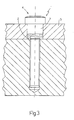
- figure 3 is a side sectional view of a portion of a plastic component clamped by means of the clamping screw in figure 1; and
- figure 4 is a side view of a variant of the clamping screw in figure 1; and
- figure 5 is a plan view of the clamping screw in figure 4.
- In figure 1,
numeral 1 indicates, as a whole, a metal clamping screw (typically formed by steel) to be inserted within a through-hole 2 of a plastic component 3 (shown in figure 3). - The
clamping screw 1 comprises ahead 4 displaying a diameter greater than the diameter of the through-hole 2, and arod 5 displaying a diameter smaller than the diameter of the through-hole 2 and having a threadedlower portion 6. - Furthermore, the
clamping screw 1 comprises anintermediate portion 7, which is arranged between thehead 4 and therod 5 and has no threads; theintermediate portion 7 displays a diameter, which is smaller than the diameter of thehead 4, greater than the diameter of therod 5, and is substantially equal to the diameter of the through-hole 2. - According to the embodiment shown in figure 1, the
clamping screw 1 also comprises a non-return washer 8, which is made in an elastic material and is arranged around therod 5 immediately below theintermediate portion 7. Preferably, the non-return washer 8 displays an external diameter equal to the diameter of theintermediate portion 7 and is arranged at a non threaded portion of therod 5. - According to the alternative embodiment shown in figure 4, the
clamping screw 1 has no non-return washer 8. - Experimental evidence has demonstrated that, in virtue of the presence of the
intermediate portion 7 which engages the through-hole 2 of theplastic component 3, the stress exerted by thehead 4 of theclamping screw 1 on the external surface of theplastic component 3 does not determine "creep" mechanisms in theplastic component 3 itself, i.e. a local plastic deformation of theplastic component 3 below thehead 4 of theclamping screw 1 is avoided. - The above described
clamping screw 1 displays many advantages, because it is easy and cost-effective to implement and at the same time, in virtue of the presence of theintermediate portion 7, it allows to avoid the use of a metal bush with a considerable reduction of the total costs of theplastic component 3.
Claims (4)
- A metal clamping screw (1) to be inserted within a through-hole (2) of a plastic component (3); the clamping screw (1) comprises:a head (4) displaying a diameter greater than the diameter of the through-hole (2); anda rod (5) displaying a diameter smaller than the diameter of the through-hole (2) and having a threaded lower portion (6);the clamping screw (1) is characterised in that it comprises an intermediate portion (7), which is arranged between the head (4) and the rod (5), has no threads, and displays a diameter smaller than the diameter of the head (4), greater than the diameter of the rod (5) and equal to the diameter of the through-hole (2).
- A clamping screw (1) according to claim 1, comprising a non-return washer (8), which is arranged around the rod (5) immediately below the intermediate portion (7).
- A clamping screw (1) according to claim 2, wherein the non-return washer (8) displays an external diameter equal to the diameter of the intermediate portion (7).
- A clamping screw (1) according to claim 2 or 3, wherein the non-return washer (8) is arranged at a non-threaded portion of the rod (5).
Priority Applications (1)
| Application Number | Priority Date | Filing Date | Title |
|---|---|---|---|
| EP06425790A EP1925829A1 (en) | 2006-11-21 | 2006-11-21 | A metal clamping screw for plastic component |
Applications Claiming Priority (1)
| Application Number | Priority Date | Filing Date | Title |
|---|---|---|---|
| EP06425790A EP1925829A1 (en) | 2006-11-21 | 2006-11-21 | A metal clamping screw for plastic component |
Publications (1)
| Publication Number | Publication Date |
|---|---|
| EP1925829A1 true EP1925829A1 (en) | 2008-05-28 |
Family
ID=37969907
Family Applications (1)
| Application Number | Title | Priority Date | Filing Date |
|---|---|---|---|
| EP06425790A Withdrawn EP1925829A1 (en) | 2006-11-21 | 2006-11-21 | A metal clamping screw for plastic component |
Country Status (1)
| Country | Link |
|---|---|
| EP (1) | EP1925829A1 (en) |
Citations (6)
| Publication number | Priority date | Publication date | Assignee | Title |
|---|---|---|---|---|
| US4797022A (en) * | 1987-01-09 | 1989-01-10 | Textron Inc. | Fastener and fabrication method therefor |
| JPH07224825A (en) * | 1994-02-10 | 1995-08-22 | Daiwa Kasei Kogyo Kk | Part fitting structure |
| DE29502068U1 (en) * | 1995-02-10 | 1996-06-13 | Gebrüder Kömmerling Kunststoffwerke GmbH, 66954 Pirmasens | Screw, especially for plastic window profiles |
| FR2780458A1 (en) * | 1998-06-24 | 1999-12-31 | Coutier Moulage Gen Ind | Fixing screw between synthetic material and metal piece |
| EP1650444A1 (en) * | 2004-10-20 | 2006-04-26 | LuK Lamellen und Kupplungsbau Beteiligungs KG | Assembly for fastening a plastic component to a support element |
| WO2006100841A1 (en) * | 2005-03-24 | 2006-09-28 | Ckd Corporation | Block fixing structure and integrated valve |
-
2006
- 2006-11-21 EP EP06425790A patent/EP1925829A1/en not_active Withdrawn
Patent Citations (6)
| Publication number | Priority date | Publication date | Assignee | Title |
|---|---|---|---|---|
| US4797022A (en) * | 1987-01-09 | 1989-01-10 | Textron Inc. | Fastener and fabrication method therefor |
| JPH07224825A (en) * | 1994-02-10 | 1995-08-22 | Daiwa Kasei Kogyo Kk | Part fitting structure |
| DE29502068U1 (en) * | 1995-02-10 | 1996-06-13 | Gebrüder Kömmerling Kunststoffwerke GmbH, 66954 Pirmasens | Screw, especially for plastic window profiles |
| FR2780458A1 (en) * | 1998-06-24 | 1999-12-31 | Coutier Moulage Gen Ind | Fixing screw between synthetic material and metal piece |
| EP1650444A1 (en) * | 2004-10-20 | 2006-04-26 | LuK Lamellen und Kupplungsbau Beteiligungs KG | Assembly for fastening a plastic component to a support element |
| WO2006100841A1 (en) * | 2005-03-24 | 2006-09-28 | Ckd Corporation | Block fixing structure and integrated valve |
Similar Documents
| Publication | Publication Date | Title |
|---|---|---|
| US6769409B2 (en) | Fuel injector supporting device | |
| EP2325443A3 (en) | Attaching ceramic matrix composite to high temperature gas turbine structure | |
| US8740532B2 (en) | Stud fasteners for fastening a cylinder head to an engine block and kit containing said stud fasteners | |
| US20130121786A1 (en) | Screw assembly element | |
| US10683885B2 (en) | Dual purpose threaded insert/compression limiter | |
| EP2837835A1 (en) | Attachment device for non-permanently attaching a child component to a parent component | |
| JP4712705B2 (en) | Double nut for controlled installation of components by bolt connection | |
| US8490595B2 (en) | Fastening system | |
| US20130056613A1 (en) | Grommet Mounting Assembly | |
| KR101727659B1 (en) | Repairing method of the bolt hole of clamp bolt for a fuel injector | |
| US10907574B2 (en) | Screw connection system for a plastic component and a metal component | |
| US20100180853A1 (en) | Automotive engine bearing | |
| JP6057417B2 (en) | Ground anchor head structure | |
| CN211474282U (en) | Cylinder cap easy to assemble and dismantle | |
| EP2341221A1 (en) | Device for mounting the cylinder head of an engine | |
| CA3101814C (en) | Nut clips for attaching objects to a pole | |
| CN104024601B (en) | Exhaust turbine supercharger | |
| CN204025296U (en) | A kind of nut | |
| US20080006234A1 (en) | Fastening structure for a cylinder block | |
| EP2395252A1 (en) | Connecting arrangement and method for fastening a bolt | |
| CN201241908Y (en) | Anti-twisting snap riveting nut | |
| CN205446341U (en) | Hexagon nut | |
| CN110815128B (en) | Test piece dismantling device and dismantling method | |
| CN212337982U (en) | Connecting mechanism of elastic reed | |
| CN220792230U (en) | Pneumatic film regulating valve |
Legal Events
| Date | Code | Title | Description |
|---|---|---|---|
| PUAI | Public reference made under article 153(3) epc to a published international application that has entered the european phase |
Free format text: ORIGINAL CODE: 0009012 |
|
| AK | Designated contracting states |
Kind code of ref document: A1 Designated state(s): AT BE BG CH CY CZ DE DK EE ES FI FR GB GR HU IE IS IT LI LT LU LV MC NL PL PT RO SE SI SK TR |
|
| AX | Request for extension of the european patent |
Extension state: AL BA HR MK RS |
|
| AKX | Designation fees paid | ||
| REG | Reference to a national code |
Ref country code: DE Ref legal event code: 8566 |
|
| STAA | Information on the status of an ep patent application or granted ep patent |
Free format text: STATUS: THE APPLICATION IS DEEMED TO BE WITHDRAWN |
|
| 18D | Application deemed to be withdrawn |
Effective date: 20081129 |