EP1925818A2 - Schott eines Rotors einer Windenergieanlage - Google Patents
Schott eines Rotors einer Windenergieanlage Download PDFInfo
- Publication number
- EP1925818A2 EP1925818A2 EP07022094A EP07022094A EP1925818A2 EP 1925818 A2 EP1925818 A2 EP 1925818A2 EP 07022094 A EP07022094 A EP 07022094A EP 07022094 A EP07022094 A EP 07022094A EP 1925818 A2 EP1925818 A2 EP 1925818A2
- Authority
- EP
- European Patent Office
- Prior art keywords
- bulkhead
- rotor
- rotor blade
- blade
- openings
- Prior art date
- Legal status (The legal status is an assumption and is not a legal conclusion. Google has not performed a legal analysis and makes no representation as to the accuracy of the status listed.)
- Granted
Links
Images

Classifications
-
- F—MECHANICAL ENGINEERING; LIGHTING; HEATING; WEAPONS; BLASTING
- F03—MACHINES OR ENGINES FOR LIQUIDS; WIND, SPRING, OR WEIGHT MOTORS; PRODUCING MECHANICAL POWER OR A REACTIVE PROPULSIVE THRUST, NOT OTHERWISE PROVIDED FOR
- F03D—WIND MOTORS
- F03D1/00—Wind motors with rotation axis substantially parallel to the air flow entering the rotor
- F03D1/06—Rotors
- F03D1/065—Rotors characterised by their construction elements
- F03D1/0658—Arrangements for fixing wind-engaging parts to a hub
-
- F—MECHANICAL ENGINEERING; LIGHTING; HEATING; WEAPONS; BLASTING
- F03—MACHINES OR ENGINES FOR LIQUIDS; WIND, SPRING, OR WEIGHT MOTORS; PRODUCING MECHANICAL POWER OR A REACTIVE PROPULSIVE THRUST, NOT OTHERWISE PROVIDED FOR
- F03D—WIND MOTORS
- F03D80/00—Details, components or accessories not provided for in groups F03D1/00 - F03D17/00
- F03D80/50—Maintenance or repair
-
- F—MECHANICAL ENGINEERING; LIGHTING; HEATING; WEAPONS; BLASTING
- F05—INDEXING SCHEMES RELATING TO ENGINES OR PUMPS IN VARIOUS SUBCLASSES OF CLASSES F01-F04
- F05B—INDEXING SCHEME RELATING TO WIND, SPRING, WEIGHT, INERTIA OR LIKE MOTORS, TO MACHINES OR ENGINES FOR LIQUIDS COVERED BY SUBCLASSES F03B, F03D AND F03G
- F05B2230/00—Manufacture
- F05B2230/80—Repairing, retrofitting or upgrading methods
-
- Y—GENERAL TAGGING OF NEW TECHNOLOGICAL DEVELOPMENTS; GENERAL TAGGING OF CROSS-SECTIONAL TECHNOLOGIES SPANNING OVER SEVERAL SECTIONS OF THE IPC; TECHNICAL SUBJECTS COVERED BY FORMER USPC CROSS-REFERENCE ART COLLECTIONS [XRACs] AND DIGESTS
- Y02—TECHNOLOGIES OR APPLICATIONS FOR MITIGATION OR ADAPTATION AGAINST CLIMATE CHANGE
- Y02E—REDUCTION OF GREENHOUSE GAS [GHG] EMISSIONS, RELATED TO ENERGY GENERATION, TRANSMISSION OR DISTRIBUTION
- Y02E10/00—Energy generation through renewable energy sources
- Y02E10/70—Wind energy
- Y02E10/72—Wind turbines with rotation axis in wind direction
-
- Y—GENERAL TAGGING OF NEW TECHNOLOGICAL DEVELOPMENTS; GENERAL TAGGING OF CROSS-SECTIONAL TECHNOLOGIES SPANNING OVER SEVERAL SECTIONS OF THE IPC; TECHNICAL SUBJECTS COVERED BY FORMER USPC CROSS-REFERENCE ART COLLECTIONS [XRACs] AND DIGESTS
- Y02—TECHNOLOGIES OR APPLICATIONS FOR MITIGATION OR ADAPTATION AGAINST CLIMATE CHANGE
- Y02P—CLIMATE CHANGE MITIGATION TECHNOLOGIES IN THE PRODUCTION OR PROCESSING OF GOODS
- Y02P70/00—Climate change mitigation technologies in the production process for final industrial or consumer products
- Y02P70/50—Manufacturing or production processes characterised by the final manufactured product
Definitions
- the invention relates to a bulkhead of a wind power plant, which is or will be arranged in or on the blade root of a rotor blade or in the region between the blade root of a rotor blade and a rotor hub.
- the invention relates to a rotor blade and the arrangement of a bulkhead on a rotor blade or on a rotor hub of a wind turbine.
- Wind turbines are known in the art.
- the wind turbines have at least one rotor blade, which is arranged on a rotor hub.
- a bulkhead is formed in the blade root of the rotor blade so that personnel can position themselves on the bulkhead with appropriate positioning during maintenance work in the rotor hub or in the rotor blade and carry out maintenance work.
- the bulkhead In order to get out of the rotor hub into the rotor blade, the bulkhead usually has a hatch or a passage hatch in the middle of the bulkhead.
- the object of the present invention is to develop a bulkhead of a wind turbine, so that the bulkhead can also be used in rotor blades with a larger blade connection diameter.
- a bulkhead of a wind turbine which is or is arranged in or on the blade root of a rotor blade or in the region between the blade root of a rotor blade and a rotor hub, which is further developed in that the bulkhead has at least two through-openings.
- the through-openings are each dimensioned so that a person, for example, from the rotor hub in the rotor blade with appropriate Position of the rotor blade rise or can get.
- the through-openings In order to stand securely on the bulkhead, the through-openings have corresponding hatch flaps so that the bulkhead serves as a working platform during maintenance work.
- the through-hatches are arranged at corresponding preferred locations, preferably outside the center of the bulkhead, so that maintenance personnel can open a closure hatch at the through-opening in a simple manner and can get into the rotor blade through the latter.
- the through-openings are placed in such a way that the access is simplified accordingly.
- At least one passage opening is arranged outside the center of the bulkhead or between the middle of the bulkhead and the edge of the bulkhead.
- the center of the bulkhead is understood to be the point through which the rotor blade axis of rotation or the rotor blade longitudinal axis runs transversely, in particular perpendicular, to the plane of the bulkhead.
- a facilitated access to the rotor blades is obtained in particular if a plurality of through-openings are formed or provided on the outer edge of the bulkhead.
- At least two through-openings with respect to the center of the bulkhead or the axis of rotation of the rotor blade, are offset by a predetermined angle between 45 ° and 180 ° with respect to each other.
- Preferred angles between two passage openings are in particular angles of 90 ° and 180 °.
- a simplified maintenance of a rotor blade results when the through-openings are or are arranged in the region of the nose of the rotor blade and / or in the region of the pressure side of the rotor blade and / or in the region of the suction side of the rotor blade, preferably at the edge of the rotor blade.
- the bulkhead is circular, wherein the bulkhead are or are connected via corresponding flange connections or the like to the rotor blade and / or the rotor hub.
- An inventive and advantageous bulkhead with a plurality of through-openings results in particular when the bulkhead has a diameter of more than 2 m, in particular more than 2.5 m, preferably more than 3.0 m.
- the through-openings are designed to be closed.
- Corresponding closing devices are familiar to the person skilled in the art and known.
- a rotor blade which is formed with a bulkhead according to the invention.
- a corresponding rotor hub and a rotor having at least one rotor blade and a rotor hub are provided with a bulkhead according to the invention or are.
- FIG. 1 shows a schematic representation of a wind power plant 10.
- the wind power plant 10 has a tower 11 and a rotor 12, which comprises three rotor blades 14, which are mounted on a rotor hub.
- the rotor hub 9 is connected to a rotor shaft.
- the rotor 12 rotates in a conventional manner.
- power can be generated by a generator connected to the rotor 12 or to the generator connected via the rotor hub 9 and the rotor shaft 13 and delivered to a consumer network.
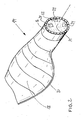
- Fig. 2 shows a lower portion of the rotor blade 14 in a perspective view.
- the rotor blade 14 has on the side facing the rotor hub on a so-called rotor blade root 16, which is formed in cross-section generally circular or circular.
- the rotor blade 14 itself is hollow in the interior.
- the rotor blade 14 is formed profiled between the rotor blade root 16 and the rotor blade tip and has a pressure side 18.
- the pressure side 18 is assigned to the associated suction side on the opposite side not designated here.
- a bulkhead 22 is arranged in the rotor blade 14, it being possible in one embodiment to glue the bulkhead 22 into the rotor blade root 16.
- the bulkhead 22 is fixedly mounted to the rotor blade root 16 or inserted therein.
- the bulkhead 22 is also circular in shape and has three vias 24 located outside the midpoint M of the bulkhead 22.
- the naturalsteigeöticianen 24 are dimensioned so that a person after opening a hatch at the Through hole 24 can rise from the rotor hub into the interior of the rotor blade 14.
- the bulkhead 22 can be used as a suitable working platform for maintenance work on the rotor hub or on the rotor blade 14.
- the through-openings 24 are arranged distributed on the outer circumference of the bulkhead 22, wherein the through-openings 24 are arranged offset by an angle of 90 °.
- axis of rotation 26 of the rotor blade 14 is indicated by a dash-dotted line perpendicular pierces the bulkhead 22 at the point M in the geometric sense.
Landscapes
- Engineering & Computer Science (AREA)
- Life Sciences & Earth Sciences (AREA)
- Sustainable Development (AREA)
- Sustainable Energy (AREA)
- Chemical & Material Sciences (AREA)
- Combustion & Propulsion (AREA)
- Mechanical Engineering (AREA)
- General Engineering & Computer Science (AREA)
- Wind Motors (AREA)
Abstract
Description
- Die Erfindung betrifft ein Schott einer Windenergieanlage, das in oder an der Blattwurzel eines Rotorblatts oder im Bereich zwischen der Blattwurzel eines Rotorblatts und einer Rotornabe angeordnet ist oder wird.
- Darüber hinaus betrifft die Erfindung ein Rotorblatt sowie die Anordnung eines Schotts an einem Rotorblatt oder an einer Rotornabe einer Windenergieanlage.
- Windenergieanlagen sind im Stand der Technik bekannt. Hierbei weisen die Windenergieanlagen mindestens ein Rotorblatt auf, das an einer Rotornabe angeordnet ist. In der Blattwurzel des Rotorblatts ist aus Sicherheitsgründen ein Schott ausgebildet, so dass bei Wartungsarbeiten in der Rotornabe oder im Rotorblatt Personal bei entsprechender Positionierung auf dem Schott steht und Wartungsarbeiten durchführen kann.
- Um aus der Rotornabe in das Rotorblatt zu gelangen, verfügt das Schott in der Regel über eine Luke bzw. eine Durchsteigeluke in der Mitte des Schotts.
- In
DE 20 2004 003 521 U1 ist eine innen begehbare Rotornabe beschrieben, die ein im Bereich ihres Ringflansches angeordnetes Aussteifungsschott aufweist. Dieses Aussteifungsschott weist in der Mitte eine Durchsteigeöffnung für das Wartungspersonal auf. - Ausgehend von diesem Stand der Technik besteht die Aufgabe der vorliegenden Erfindung darin, ein Schott einer Windenergieanlage weiterzubilden, so dass das Schott auch bei Rotorblättern mit einem größeren Blattanschlussdurchmesser eingesetzt werden kann.
- Die Lösung der Aufgabe erfolgt durch ein Schott einer Windenergieanlage, das in oder an der Blattwurzel eines Rotorblatts oder im Bereich zwischen der Blattwurzel eines Rotorblatts und einer Rotornabe angeordnet ist oder wird, das dadurch weitergebildet ist, dass das Schott wenigstens zwei Durchsteigeöffnungen aufweist.
- Dadurch, dass wenigstens zwei Durchsteigeöffnungen im Schott im Durchgang zwischen der Rotornabe und dem Rotorblatt ausgebildet sind, ist es beispielsweise möglich, dass bei Verunfallung einer Person, die durch eine Durchsteigeöffnung in das Rotorblatt eingestiegen ist, eine Rettungsperson über die zweite Durchsteigeöffnung in das Rotorblatt einsteigt, um die verunfallte Person zu retten. Hierdurch ergibt sich eine schnellere und einfachere Möglichkeit, Personen aus dem Rotorblatt zu retten. Dadurch werden die Sicherheitsmaßnahmen an einer Windenergieanlage wesentlich erhöht.
- Die Durchsteigeöffnungen sind jeweils so dimensioniert, dass eine Person beispielsweise aus der Rotornabe in das Rotorblatt bei entsprechender Stellung des Rotorblatts steigen bzw. gelangen kann. Um sicher auf dem Schott zu stehen, verfügen die Durchsteigeöffnungen über entsprechende Lukenklappen, so dass das Schott als Arbeitsplattform bei Wartungsarbeiten dient.
- Darüber hinaus wird der Zugang zu Rotorblättern aus der Rotornabe erleichtert, wenn mehrere Durchsteigeöffnungen am Schott vorgesehen sind, da beispielsweise beim Herstellen von großen Rotornaben und großen Rotorblättern, beispielsweise mit einem Blattwurzeldurchmesser von etwa 3 m, die Zugangsmöglichkeiten und somit die Wartung erleichtert werden.
- Hierbei sind die Durchsteigeluken an entsprechenden bevorzugten Orten, vorzugsweise außerhalb der Mitte des Schotts, angeordnet, so dass Wartungspersonal auf einfache Weise eine Verschlussluke an der Durchsteigeöffnung öffnen und durch diese in das Rotorblatt einsteigen kann. Insbesondere sind die Durchsteigeöffnungen derart platziert, dass der Zugang entsprechend vereinfacht wird.
- Darüber hinaus ist in einer bevorzugten Ausführungsform vorgesehen, dass wenigstens eine Durchsteigeöffnung außerhalb der Mitte des Schotts oder zwischen der Mitte des Schotts und dem Rand des Schotts angeordnet ist. Unter der Mitte des Schotts wird der Punkt verstanden, durch den die Rotorblattdrehachse oder die Rotorblattlängsachse quer, insbesondere senkrecht, zur Ebene des Schotts verläuft.
- Ein erleichterter Zugang zu den Rotorblättern ergibt sich insbesondere dann, wenn mehrere Durchsteigeöffnungen am äußeren Rand des Schotts ausgebildet oder vorgesehen sind.
- Besonders ist es bevorzugt, wenn wenigstens zwei Durchsteigeöffnungen, bezogen auf die Mitte des Schotts oder die Drehachse des Rotorblatts, um einen vorbestimmten Winkel zwischen 45° und 180° zueinander versetzt angeordnet sind. Bevorzugte Winkel zwischen zwei Durchsteigeöffnungen sind insbesondere Winkel von 90° und 180°.
- Eine vereinfachte Wartung eines Rotorblatts ergibt sich dann, wenn die Durchsteigeöffnungen im Bereich der Nase des Rotorblatts und/oder im Bereich der Druckseite des Rotorblatts und/oder im Bereich der Saugseite des Rotorblatts, vorzugsweise am Rand des Rotorblatts, angeordnet sind oder werden.
- Insbesondere ist das Schott kreisförmig ausgebildet, wobei das Schott über entsprechende Flanschverbindungen oder dergleichen mit dem Rotorblatt und/oder der Rotornabe verbunden sind oder werden.
- Ein erfindungsgemäßes und vorteilhaftes Schott mit mehreren Durchsteigeöffnungen ergibt sich insbesondere dann, wenn das Schott einen Durchmesser von mehr als 2 m, insbesondere mehr als 2,5 m, vorzugsweise mehr als 3,0 m aufweist. Dadurch ist es möglich, dass auch größere Windenergieanlagen, bei denen die Rotorblätter einen Rotorblattdurchmesser von mehr als 2 m, 2, 5 oder 3 m oder mehr haben, mit einem erfindungsgemäßen Schott versehen werden, wodurch die Wartung der Rotorblätter oder auch die Rettung von verunfallten Personen vereinfacht wird.
- Darüber hinaus sind die Durchsteigeöffnungen verschließbar ausgebildet. Entsprechende Schließeinrichtungen sind dem Fachmann geläufig und bekannt.
- Überdies wird die Aufgabe gelöst durch ein Rotorblatt, das mit einem erfindungsgemäßen Schott ausgebildet ist. Im Rahmen der Erfindung ist es auch möglich, dass eine entsprechende Rotornabe sowie ein Rotor, der wenigstens ein Rotorblatt und eine Rotornabe aufweist, mit einem erfindungsgemäßen Schott versehen werden oder sind.
- Außerdem erfolgt eine weitere Lösung der Aufgabe durch eine Anordnung eines Schotts an oder in einem Rotorblatt einer Windenergieanlage im Bereich der Blattwurzel oder an einer Rotornabe einer Windenergieanlage oder durch eine Anordnung eines Schotts im Bereich zwischen einem Rotorblatt und einer Rotornabe. Zu weiteren Einzelheiten und zur Vermeidung von Wiederholungen wird auf die vorangehenden Ausführungen des Schotts verwiesen.
- Die Erfindung wird nachstehend ohne Beschränkung des allgemeinen Erfindungsgedankens anhand von Ausführungsbeispielen unter Bezugnahme auf die Zeichnungen beschrieben, wobei bezüglich aller im Text nicht näher erläuterten erfindungsgemäßen Einzelheiten ausdrücklich auf die Zeichnungen verwiesen wird. Es zeigen:
- Fig.1
- eine schematische Darstellung einer Windenergieanlage und
- Fig. 2
- eine perspektivische Ansicht eines Rotorblatts mit einem erfindungsgemäßen Schott.
- In den folgenden Figuren sind jeweils gleiche oder gleichartige Elemente bzw. entsprechende Teile mit denselben Bezugsziffern versehen, so dass von einer entsprechenden erneuten Vorstellung abgesehen wird.
- Fig. 1 zeigt eine schematische Darstellung einer Windenergieanlage 10. Die Windenergieanlage 10 weist einen Turm 11 auf und einen Rotor 12, der drei Rotorblätter 14 umfasst, die auf einer Rotornabe angebracht sind. Die Rotornabe 9 ist mit einer Rotorwelle verbunden. Bei Windanfall dreht sich der Rotor 12 in an sich bekannter Weise. Hierdurch kann Leistung von einem an den Rotor 12 bzw. an den über die Rotornabe 9 und die Rotorwelle 13 angeschlossenen Generator erzeugt werden und in ein Verbrauchernetz abgegeben werden.
- Fig. 2 zeigt einen unteren Abschnitt des Rotorblatts 14 in einer perspektivischen Darstellung. Das Rotorblatt 14 verfügt auf der der Rotornabe zugewandten Seite über eine so genannte Rotorblattwurzel 16, die im Querschnitt im Allgemeinen kreisförmig bzw. kreisrund ausgebildet ist. Das Rotorblatt 14 selbst ist im Innenraum hohl. Das Rotorblatt 14 ist zwischen der Rotorblattwurzel 16 und der Rotorblattspitze profiliert ausgebildet und verfügt über eine Druckseite 18. Der Druckseite 18 ist auf der hier nicht bezeichneten gegenüber liegenden Seite die dazugehörige Saugseite zugeordnet.
- Die entsprechenden Rotorblattprofile entlang der Längsachse des Rotorblatts 14 laufen an der Hinterkante 20 des Rotorblatts 14 zusammen. Im Bereich der Rotorblattwurzel 16 ist ein Schott 22 in dem Rotorblatt 14 angeordnet, wobei es in einer Ausgestaltung möglich ist, das Schott 22 in die Rotorblattwurzel 16 einzukleben. Das Schott 22 ist fest an der Rotorblattwurzel 16 montiert oder darin eingesetzt.
- Das Schott 22 ist ebenfalls kreisförmig ausgebildet und verfügt über drei Durchsteigeöffnungen 24, die außerhalb des Mittelpunkts M des Schotts 22 angeordnet sind. Die Durchsteigeöffnungen 24 sind so dimensioniert, dass eine Person nach Öffnung einer Luke an der Durchsteigeöffnung 24 von der Rotornabe in den Innenraum des Rotorblatts 14 steigen kann.
- Dadurch, dass mehrere Durchsteigeöffnungen am Schott 22 ausgebildet sind, wird ein einfacher und sicherer Ein- bzw. Ausgang an den Rotorblättern 14 auch bei großen Durchmessern der Rotorblattwurzel 16, beispielsweise größer als 2 m oder 2,5 m oder 3,0 m sichergestellt.
- Durch das Schott 22 wird ein Hineinfallen von Gegenständen oder von Personen aus der Rotornabe in das Rotorblatt 14 verhindert sowie das Rotorblatt 14 gegenüber der Rotornabe bezüglich Schmutz und/oder Feuchtigkeit abgedichtet. Gleichzeitig kann das Schott 22 als entsprechende Arbeitsplattform bei Wartungsarbeiten an der Rotornabe oder am Rotorblatt 14 eingesetzt werden. Die Durchsteigeöffnungen 24 sind am äußeren Umfang des Schotts 22 verteilt angeordnet, wobei die Durchsteigeöffnungen 24 um einen Winkel von 90° versetzt angeordnet sind. Dadurch ist es möglich, beispielsweise die Durchsteigeöffnungen 24 in einer entsprechenden 12 Uhr-, 3 Uhr- und 6 Uhr-Position (bzw. 3 Uhr-, 6 Uhr-, 9 Uhr-Position) anzuordnen, wenn das Rotorblatt 14 zu Wartungsarbeiten mit der Vorderkante, d.h. mit der Anströmseite bei horizontal angeordnetem Rotorblatt 14 an der Windenergieanlage gelagert ist. Diese Positionen entsprechen den Anordnungen der Durchsteigeöffnungen im Bereich der Druckseite, der Nase und der Saugseite.
- Darüber hinaus ist in Fig. 2 die Drehachse 26 des Rotorblatts 14 mit einer strich-punktierten Linie eingezeichnet, die senkrecht das Schott 22 im Punkt M im geometrischen Sinne durchsticht.
-
- 9
- Rotornabe
- 10
- Windenergieanlage
- 11
- Turm
- 12
- Rotor
- 14
- Rotorblatt
- 16
- Rotorblattwurzel
- 18
- Druckseite
- 20
- Hinterkante
- 22
- Schott
- 24
- Durchsteigeöffnung
- M
- Mittelpunkt
Claims (10)
- Schott (22) einer Windenergieanlage (10), das in oder an der Blattwurzel (16) eines Rotorblatts (14) oder im Bereich zwischen der Blattwurzel (16) eines Rotorblatts (14) und einer Rotornabe (9) angeordnet ist oder wird, dadurch gekennzeichnet, dass das Schott (22) wenigstens zwei Durchsteigeöffnungen (24) aufweist.
- Schott (22) nach Anspruch 1, dadurch gekennzeichnet, dass wenigstens eine Durchsteigeöffnung (24) außerhalb der Mitte des Schotts (22) oder zwischen der Mitte des Schotts (22) und dem Rand des Schotts (22) angeordnet ist.
- Schott (22) nach Anspruch 1 oder 2, dadurch gekennzeichnet, dass mehrere Durchsteigeöffnungen (24) am Rand des Schotts (22) ausgebildet sind.
- Schott (22) nach einem der Ansprüche 1 bis 3, dadurch gekennzeichnet, dass wenigstens zwei Durchsteigeöffnungen (24), bezogen auf die Mitte (M) des Schotts (22), um einen vorbestimmten Winkel zwischen 45° und 180° zueinander versetzt angeordnet sind.
- Schott (22) nach einem der Ansprüche 1 bis 4, dadurch gekennzeichnet, dass die Durchsteigeöffnungen (24) im Bereich der Nase des Rotorblatts (14) und/oder im Bereich der Druckseite (18) des Rotorblatts (14) und/oder im Bereich der Saugseite des Rotorblatts (14), vorzugsweise am Rand des Rotorblatts (14), angeordnet sind oder werden.
- Schott (22) nach einem der Ansprüche 1 bis 5, dadurch gekennzeichnet, dass das Schott (22) kreisförmig ausgebildet ist.
- Schott (22) nach einem der Ansprüche 1 bis 6, dadurch gekennzeichnet, dass das Schott (22) einen Durchmesser von mehr als 2 m, insbesondere mehr als 2,5 m, vorzugsweise mehr als 3,0 m aufweist.
- Schott (22) nach einem der Ansprüche 1 bis 7, dadurch gekennzeichnet, dass die Durchsteigeöffnungen (24) verschließbar ausgebildet sind.
- Rotorblatt (14) oder Rotor (12) oder Rotornabe (9) mit einem Schott (22) nach einem der Ansprüche 1 bis 8.
- Anordnung eines Schotts (22) an einem Rotorblatt (14) einer Windenergieanlage (10) oder an einer Rotornabe (9) einer Windenergieanlage (10) oder Anordnung eines Schotts (22) zwischen einem Rotorblatt (14) und einer Rotornabe (9), wobei das Schott (22) nach einem der Ansprüche 1 bis 8 ausgebildet ist.
Applications Claiming Priority (1)
| Application Number | Priority Date | Filing Date | Title |
|---|---|---|---|
| DE102006055091A DE102006055091A1 (de) | 2006-11-21 | 2006-11-21 | Schott einer Windenergieanlage |
Publications (3)
| Publication Number | Publication Date |
|---|---|
| EP1925818A2 true EP1925818A2 (de) | 2008-05-28 |
| EP1925818A3 EP1925818A3 (de) | 2009-12-23 |
| EP1925818B1 EP1925818B1 (de) | 2019-01-09 |
Family
ID=38823553
Family Applications (1)
| Application Number | Title | Priority Date | Filing Date |
|---|---|---|---|
| EP07022094.2A Active EP1925818B1 (de) | 2006-11-21 | 2007-11-14 | Rotor einer Windenergieanlage mit einem Schott |
Country Status (5)
| Country | Link |
|---|---|
| US (1) | US8096759B2 (de) |
| EP (1) | EP1925818B1 (de) |
| DE (1) | DE102006055091A1 (de) |
| DK (1) | DK1925818T3 (de) |
| ES (1) | ES2719253T3 (de) |
Cited By (4)
| Publication number | Priority date | Publication date | Assignee | Title |
|---|---|---|---|---|
| EP2447524A1 (de) * | 2010-10-29 | 2012-05-02 | General Electric Company | Gehäusesystem für eine Windturbinenwinkelverstellungsanordnung |
| EP2532882A1 (de) * | 2011-06-10 | 2012-12-12 | General Electric Company | System und Verfahren zur Montage einer Windturbine mit einer Neigungsanordnung |
| WO2013041190A1 (de) * | 2011-09-21 | 2013-03-28 | Repower Systems Se | Schott einer windturbinenschaufel |
| EP4624747A1 (de) | 2024-03-27 | 2025-10-01 | Nordex Energy SE & Co. KG | Windenergieanlagenrotorblatt mit einer bodenplatte mit durchstiegsöffnung |
Families Citing this family (13)
| Publication number | Priority date | Publication date | Assignee | Title |
|---|---|---|---|---|
| DE102010042530B4 (de) | 2010-10-15 | 2015-04-30 | Senvion Se | Schott einer Windenergieanlage |
| US8250761B2 (en) * | 2010-12-13 | 2012-08-28 | General Electric Company | Methods of manufacturing rotor blades for a wind turbine |
| DE102011077402A1 (de) | 2011-06-10 | 2012-12-13 | Repower Systems Se | Rotorblatt einer Windenergieanlage und Windenergieanlage |
| US9115698B2 (en) * | 2012-03-06 | 2015-08-25 | General Electric Company | Wind turbine with access features for gaining access to the interior of a rotor hub |
| DE102012217904A1 (de) * | 2012-10-01 | 2014-04-03 | Repower Systems Se | Faserverbundbauteil und Rotorblatt |
| EP3690233B1 (de) * | 2012-11-19 | 2022-05-11 | LM Wind Power A/S | Schottwand für das rotorblatt einer windturbine |
| DE102017004056A1 (de) * | 2017-04-27 | 2018-10-31 | Senvion Gmbh | Blattadapter für Windenergieanlagen |
| DE102018108610A1 (de) * | 2018-04-11 | 2019-10-17 | Wobben Properties Gmbh | Rotornabe einer Windenergieanlage, sowie Verfahren zur Montage einer solchen Rotornabe |
| US11415105B2 (en) * | 2018-10-22 | 2022-08-16 | Tpi Composites, Inc. | Gantry-less wind turbine web installation with heating |
| US11131290B2 (en) * | 2019-06-25 | 2021-09-28 | General Electric Company | Scarf connection for a wind turbine rotor blade |
| GB202002062D0 (en) * | 2020-02-14 | 2020-04-01 | Blade Dynamics Ltd | Wind turbine rotor blade with framed access window |
| EP4008895B1 (de) * | 2020-12-03 | 2025-09-10 | General Electric Renovables España S.L. | Wurzelabschnitt für eine windturbinenschaufel |
| EP4160003A1 (de) * | 2021-09-29 | 2023-04-05 | Siemens Gamesa Renewable Energy A/S | Verfahren zur bereitstellung von zugang zum inneren einer hohlen schaufel einer windturbine, leiterträgeranordnung und windturbine |
Citations (2)
| Publication number | Priority date | Publication date | Assignee | Title |
|---|---|---|---|---|
| DE202004003521U1 (de) | 2004-03-06 | 2004-06-24 | W2E Wind To Engergy Gmbh | Innenbegehbare Rotornabe |
| WO2004090326A1 (en) | 2003-04-12 | 2004-10-21 | General Electric Company | Reinforced hub for the rotor of a wind energy turbine |
Family Cites Families (12)
| Publication number | Priority date | Publication date | Assignee | Title |
|---|---|---|---|---|
| WO1999043955A1 (en) | 1998-02-24 | 1999-09-02 | Lm Glasfiber A/S | Wind turbine blade |
| DE29817382U1 (de) * | 1998-09-28 | 1999-02-18 | aerodyn Engineering GmbH, 24768 Rendsburg | Sicherheitskorb zum Einsteigen in die Rotornabe einer Windenergieanlage |
| DK173641B1 (da) | 1998-12-15 | 2001-05-14 | Bonus Energy As | Generator, fortrinsvis til en vindmølle |
| ITBZ20010043A1 (it) * | 2001-09-13 | 2003-03-13 | High Technology Invest Bv | Generatore elettrico azionato da energia eolica. |
| DE10201726B4 (de) | 2002-01-18 | 2004-10-21 | Wobben, Aloys, Dipl.-Ing. | Windenergieanlage |
| NL1021673C1 (nl) * | 2002-10-17 | 2004-04-20 | Mecal Applied Mechanics B V | Verbeterde naaf voor een windturbine. |
| DE10337534B4 (de) * | 2003-08-14 | 2019-12-12 | W2E Wind To Energy Gmbh | Windenergiekonverter mit einer einen Innenraum aufweisenden Rotornabe |
| DE102004023773B3 (de) * | 2004-05-11 | 2005-11-17 | Repower Systems Ag | Windenergieanlage |
| DE102004057979C5 (de) * | 2004-11-30 | 2019-09-26 | Senvion Gmbh | Rotorblatt |
| DE102004058776B3 (de) * | 2004-12-07 | 2006-07-13 | Nordex Energy Gmbh | Vorrichtung zur Belüftung einer Rotornabe einer Windenergieanlage |
| DK176019B1 (da) * | 2004-12-29 | 2005-12-12 | Lm Glasfiber As | Vinge til vindenergianlæg udstyret med opsamlingsmidler |
| US7614850B2 (en) * | 2006-07-11 | 2009-11-10 | General Electric Company | Apparatus for assembling rotary machines |
-
2006
- 2006-11-21 DE DE102006055091A patent/DE102006055091A1/de not_active Withdrawn
-
2007
- 2007-11-14 DK DK07022094.2T patent/DK1925818T3/en active
- 2007-11-14 EP EP07022094.2A patent/EP1925818B1/de active Active
- 2007-11-14 ES ES07022094T patent/ES2719253T3/es active Active
- 2007-11-20 US US11/943,021 patent/US8096759B2/en active Active
Patent Citations (2)
| Publication number | Priority date | Publication date | Assignee | Title |
|---|---|---|---|---|
| WO2004090326A1 (en) | 2003-04-12 | 2004-10-21 | General Electric Company | Reinforced hub for the rotor of a wind energy turbine |
| DE202004003521U1 (de) | 2004-03-06 | 2004-06-24 | W2E Wind To Engergy Gmbh | Innenbegehbare Rotornabe |
Cited By (4)
| Publication number | Priority date | Publication date | Assignee | Title |
|---|---|---|---|---|
| EP2447524A1 (de) * | 2010-10-29 | 2012-05-02 | General Electric Company | Gehäusesystem für eine Windturbinenwinkelverstellungsanordnung |
| EP2532882A1 (de) * | 2011-06-10 | 2012-12-12 | General Electric Company | System und Verfahren zur Montage einer Windturbine mit einer Neigungsanordnung |
| WO2013041190A1 (de) * | 2011-09-21 | 2013-03-28 | Repower Systems Se | Schott einer windturbinenschaufel |
| EP4624747A1 (de) | 2024-03-27 | 2025-10-01 | Nordex Energy SE & Co. KG | Windenergieanlagenrotorblatt mit einer bodenplatte mit durchstiegsöffnung |
Also Published As
| Publication number | Publication date |
|---|---|
| EP1925818A3 (de) | 2009-12-23 |
| DE102006055091A1 (de) | 2008-05-29 |
| DK1925818T3 (en) | 2019-04-23 |
| EP1925818B1 (de) | 2019-01-09 |
| US20080118365A1 (en) | 2008-05-22 |
| ES2719253T3 (es) | 2019-07-09 |
| US8096759B2 (en) | 2012-01-17 |
Similar Documents
| Publication | Publication Date | Title |
|---|---|---|
| EP1925818B1 (de) | Rotor einer Windenergieanlage mit einem Schott | |
| DE10201726B4 (de) | Windenergieanlage | |
| EP2035694B1 (de) | Rotornabe einer windenergieanlage | |
| EP2273101B1 (de) | Verfahren zur montage von rotorblättern einer windenergieanlage | |
| EP3129651B1 (de) | Gondel einer windenergieanlage | |
| EP3455493B1 (de) | Windenergieanlagen-rotorblatt, und windenergieanlage mit selbigem | |
| EP3396154B1 (de) | Blattadapter für windenergieanlagen | |
| EP1544458A2 (de) | Winkelregelung zur Rotorblatteinstellung für Windturbine | |
| EP3728835B1 (de) | Windkraftanlage mit rotornabenverlängerung | |
| WO2020118328A1 (de) | Planetengetriebe für eine windkraftanlage | |
| EP2627898A1 (de) | Schott einer windenergieanlage | |
| WO2014023850A1 (de) | Rotorwelle für eine windturbine | |
| DE102006053712A1 (de) | Rotorblatt und Windkraftanlage | |
| EP2718564B1 (de) | Rotorblatt einer windenergieanlage und windenergieanlage | |
| EP2985452A1 (de) | Rotorblattverlängerungskörper sowie windenergieanlage | |
| WO2010045914A2 (de) | Lageveränderlicher pitch-antrieb | |
| DE112017004377B4 (de) | Windturbinenanlage | |
| EP3775534B1 (de) | Rotornabe einer windenergieanlage, sowie verfahren zur montage einer solchen rotornabe | |
| EP2758658B1 (de) | Schott einer windturbinenschaufel | |
| DE102009007812B4 (de) | Windkraftanlage mit windschlüpfiger Profilierung | |
| EP3221578B1 (de) | Auslegung einer windenergieanlage | |
| EP3379077B1 (de) | Drehverbindung einer windenergieanlage und verzahnung für eine drehverbindung | |
| EP3380719B1 (de) | Rotorblatt einer windenergieanlage | |
| EP3438450B1 (de) | Plattform für wartungsarbeiten an einer windenergieanlage, verfahren zur montage einer solchen plattform und windenergieanlage | |
| DE102009004070A1 (de) | Windenergieanlage |
Legal Events
| Date | Code | Title | Description |
|---|---|---|---|
| PUAI | Public reference made under article 153(3) epc to a published international application that has entered the european phase |
Free format text: ORIGINAL CODE: 0009012 |
|
| AK | Designated contracting states |
Kind code of ref document: A2 Designated state(s): AT BE BG CH CY CZ DE DK EE ES FI FR GB GR HU IE IS IT LI LT LU LV MC MT NL PL PT RO SE SI SK TR |
|
| AX | Request for extension of the european patent |
Extension state: AL BA HR MK RS |
|
| PUAL | Search report despatched |
Free format text: ORIGINAL CODE: 0009013 |
|
| AK | Designated contracting states |
Kind code of ref document: A3 Designated state(s): AT BE BG CH CY CZ DE DK EE ES FI FR GB GR HU IE IS IT LI LT LU LV MC MT NL PL PT RO SE SI SK TR |
|
| AX | Request for extension of the european patent |
Extension state: AL BA HR MK RS |
|
| 17P | Request for examination filed |
Effective date: 20100210 |
|
| 17Q | First examination report despatched |
Effective date: 20100316 |
|
| AKX | Designation fees paid |
Designated state(s): AT BE BG CH CY CZ DE DK EE ES FI FR GB GR HU IE IS IT LI LT LU LV MC MT NL PL PT RO SE SI SK TR |
|
| RIN1 | Information on inventor provided before grant (corrected) |
Inventor name: QUELL, PETER Inventor name: EUSTERBARKEY, CARSTEN Inventor name: BENDEL, URS |
|
| RAP1 | Party data changed (applicant data changed or rights of an application transferred) |
Owner name: REPOWER SYSTEMS SE |
|
| RAP1 | Party data changed (applicant data changed or rights of an application transferred) |
Owner name: SENVION SE |
|
| RAP1 | Party data changed (applicant data changed or rights of an application transferred) |
Owner name: SENVION GMBH |
|
| STAA | Information on the status of an ep patent application or granted ep patent |
Free format text: STATUS: EXAMINATION IS IN PROGRESS |
|
| GRAP | Despatch of communication of intention to grant a patent |
Free format text: ORIGINAL CODE: EPIDOSNIGR1 |
|
| STAA | Information on the status of an ep patent application or granted ep patent |
Free format text: STATUS: GRANT OF PATENT IS INTENDED |
|
| INTG | Intention to grant announced |
Effective date: 20180604 |
|
| GRAS | Grant fee paid |
Free format text: ORIGINAL CODE: EPIDOSNIGR3 |
|
| GRAJ | Information related to disapproval of communication of intention to grant by the applicant or resumption of examination proceedings by the epo deleted |
Free format text: ORIGINAL CODE: EPIDOSDIGR1 |
|
| GRAL | Information related to payment of fee for publishing/printing deleted |
Free format text: ORIGINAL CODE: EPIDOSDIGR3 |
|
| STAA | Information on the status of an ep patent application or granted ep patent |
Free format text: STATUS: EXAMINATION IS IN PROGRESS |
|
| GRAJ | Information related to disapproval of communication of intention to grant by the applicant or resumption of examination proceedings by the epo deleted |
Free format text: ORIGINAL CODE: EPIDOSDIGR1 |
|
| GRAL | Information related to payment of fee for publishing/printing deleted |
Free format text: ORIGINAL CODE: EPIDOSDIGR3 |
|
| GRAR | Information related to intention to grant a patent recorded |
Free format text: ORIGINAL CODE: EPIDOSNIGR71 |
|
| STAA | Information on the status of an ep patent application or granted ep patent |
Free format text: STATUS: GRANT OF PATENT IS INTENDED |
|
| INTC | Intention to grant announced (deleted) | ||
| GRAA | (expected) grant |
Free format text: ORIGINAL CODE: 0009210 |
|
| STAA | Information on the status of an ep patent application or granted ep patent |
Free format text: STATUS: THE PATENT HAS BEEN GRANTED |
|
| INTG | Intention to grant announced |
Effective date: 20181115 |
|
| AK | Designated contracting states |
Kind code of ref document: B1 Designated state(s): AT BE BG CH CY CZ DE DK EE ES FI FR GB GR HU IE IS IT LI LT LU LV MC MT NL PL PT RO SE SI SK TR |
|
| REG | Reference to a national code |
Ref country code: GB Ref legal event code: FG4D Free format text: NOT ENGLISH |
|
| REG | Reference to a national code |
Ref country code: AT Ref legal event code: REF Ref document number: 1087628 Country of ref document: AT Kind code of ref document: T Effective date: 20190115 Ref country code: CH Ref legal event code: EP |
|
| REG | Reference to a national code |
Ref country code: DE Ref legal event code: R096 Ref document number: 502007016553 Country of ref document: DE |
|
| REG | Reference to a national code |
Ref country code: IE Ref legal event code: FG4D Free format text: LANGUAGE OF EP DOCUMENT: GERMAN |
|
| REG | Reference to a national code |
Ref country code: DK Ref legal event code: T3 Effective date: 20190415 |
|
| REG | Reference to a national code |
Ref country code: NL Ref legal event code: MP Effective date: 20190109 |
|
| REG | Reference to a national code |
Ref country code: LT Ref legal event code: MG4D |
|
| PG25 | Lapsed in a contracting state [announced via postgrant information from national office to epo] |
Ref country code: NL Free format text: LAPSE BECAUSE OF FAILURE TO SUBMIT A TRANSLATION OF THE DESCRIPTION OR TO PAY THE FEE WITHIN THE PRESCRIBED TIME-LIMIT Effective date: 20190109 |
|
| REG | Reference to a national code |
Ref country code: ES Ref legal event code: FG2A Ref document number: 2719253 Country of ref document: ES Kind code of ref document: T3 Effective date: 20190709 |
|
| PG25 | Lapsed in a contracting state [announced via postgrant information from national office to epo] |
Ref country code: PT Free format text: LAPSE BECAUSE OF FAILURE TO SUBMIT A TRANSLATION OF THE DESCRIPTION OR TO PAY THE FEE WITHIN THE PRESCRIBED TIME-LIMIT Effective date: 20190509 Ref country code: SE Free format text: LAPSE BECAUSE OF FAILURE TO SUBMIT A TRANSLATION OF THE DESCRIPTION OR TO PAY THE FEE WITHIN THE PRESCRIBED TIME-LIMIT Effective date: 20190109 Ref country code: PL Free format text: LAPSE BECAUSE OF FAILURE TO SUBMIT A TRANSLATION OF THE DESCRIPTION OR TO PAY THE FEE WITHIN THE PRESCRIBED TIME-LIMIT Effective date: 20190109 Ref country code: LT Free format text: LAPSE BECAUSE OF FAILURE TO SUBMIT A TRANSLATION OF THE DESCRIPTION OR TO PAY THE FEE WITHIN THE PRESCRIBED TIME-LIMIT Effective date: 20190109 Ref country code: FI Free format text: LAPSE BECAUSE OF FAILURE TO SUBMIT A TRANSLATION OF THE DESCRIPTION OR TO PAY THE FEE WITHIN THE PRESCRIBED TIME-LIMIT Effective date: 20190109 |
|
| PG25 | Lapsed in a contracting state [announced via postgrant information from national office to epo] |
Ref country code: BG Free format text: LAPSE BECAUSE OF FAILURE TO SUBMIT A TRANSLATION OF THE DESCRIPTION OR TO PAY THE FEE WITHIN THE PRESCRIBED TIME-LIMIT Effective date: 20190409 Ref country code: IS Free format text: LAPSE BECAUSE OF FAILURE TO SUBMIT A TRANSLATION OF THE DESCRIPTION OR TO PAY THE FEE WITHIN THE PRESCRIBED TIME-LIMIT Effective date: 20190509 Ref country code: GR Free format text: LAPSE BECAUSE OF FAILURE TO SUBMIT A TRANSLATION OF THE DESCRIPTION OR TO PAY THE FEE WITHIN THE PRESCRIBED TIME-LIMIT Effective date: 20190410 Ref country code: LV Free format text: LAPSE BECAUSE OF FAILURE TO SUBMIT A TRANSLATION OF THE DESCRIPTION OR TO PAY THE FEE WITHIN THE PRESCRIBED TIME-LIMIT Effective date: 20190109 |
|
| REG | Reference to a national code |
Ref country code: DE Ref legal event code: R026 Ref document number: 502007016553 Country of ref document: DE |
|
| PLBI | Opposition filed |
Free format text: ORIGINAL CODE: 0009260 |
|
| PLBI | Opposition filed |
Free format text: ORIGINAL CODE: 0009260 |
|
| PLAX | Notice of opposition and request to file observation + time limit sent |
Free format text: ORIGINAL CODE: EPIDOSNOBS2 |
|
| PG25 | Lapsed in a contracting state [announced via postgrant information from national office to epo] |
Ref country code: CZ Free format text: LAPSE BECAUSE OF FAILURE TO SUBMIT A TRANSLATION OF THE DESCRIPTION OR TO PAY THE FEE WITHIN THE PRESCRIBED TIME-LIMIT Effective date: 20190109 Ref country code: RO Free format text: LAPSE BECAUSE OF FAILURE TO SUBMIT A TRANSLATION OF THE DESCRIPTION OR TO PAY THE FEE WITHIN THE PRESCRIBED TIME-LIMIT Effective date: 20190109 Ref country code: IT Free format text: LAPSE BECAUSE OF FAILURE TO SUBMIT A TRANSLATION OF THE DESCRIPTION OR TO PAY THE FEE WITHIN THE PRESCRIBED TIME-LIMIT Effective date: 20190109 Ref country code: SK Free format text: LAPSE BECAUSE OF FAILURE TO SUBMIT A TRANSLATION OF THE DESCRIPTION OR TO PAY THE FEE WITHIN THE PRESCRIBED TIME-LIMIT Effective date: 20190109 Ref country code: EE Free format text: LAPSE BECAUSE OF FAILURE TO SUBMIT A TRANSLATION OF THE DESCRIPTION OR TO PAY THE FEE WITHIN THE PRESCRIBED TIME-LIMIT Effective date: 20190109 |
|
| 26 | Opposition filed |
Opponent name: NORDEX ENERGY GMBH Effective date: 20191009 Opponent name: VESTAS WIND SYSTEMS A/S Effective date: 20191008 |
|
| 26 | Opposition filed |
Opponent name: LM WP PATENT HOLDING A/S LM WIND POWER A/S Effective date: 20191009 |
|
| PLBB | Reply of patent proprietor to notice(s) of opposition received |
Free format text: ORIGINAL CODE: EPIDOSNOBS3 |
|
| PG25 | Lapsed in a contracting state [announced via postgrant information from national office to epo] |
Ref country code: SI Free format text: LAPSE BECAUSE OF FAILURE TO SUBMIT A TRANSLATION OF THE DESCRIPTION OR TO PAY THE FEE WITHIN THE PRESCRIBED TIME-LIMIT Effective date: 20190109 |
|
| PG25 | Lapsed in a contracting state [announced via postgrant information from national office to epo] |
Ref country code: TR Free format text: LAPSE BECAUSE OF FAILURE TO SUBMIT A TRANSLATION OF THE DESCRIPTION OR TO PAY THE FEE WITHIN THE PRESCRIBED TIME-LIMIT Effective date: 20190109 |
|
| REG | Reference to a national code |
Ref country code: CH Ref legal event code: PL |
|
| PG25 | Lapsed in a contracting state [announced via postgrant information from national office to epo] |
Ref country code: MC Free format text: LAPSE BECAUSE OF FAILURE TO SUBMIT A TRANSLATION OF THE DESCRIPTION OR TO PAY THE FEE WITHIN THE PRESCRIBED TIME-LIMIT Effective date: 20190109 Ref country code: CH Free format text: LAPSE BECAUSE OF NON-PAYMENT OF DUE FEES Effective date: 20191130 Ref country code: LU Free format text: LAPSE BECAUSE OF NON-PAYMENT OF DUE FEES Effective date: 20191114 Ref country code: LI Free format text: LAPSE BECAUSE OF NON-PAYMENT OF DUE FEES Effective date: 20191130 |
|
| REG | Reference to a national code |
Ref country code: BE Ref legal event code: MM Effective date: 20191130 |
|
| PG25 | Lapsed in a contracting state [announced via postgrant information from national office to epo] |
Ref country code: IE Free format text: LAPSE BECAUSE OF NON-PAYMENT OF DUE FEES Effective date: 20191114 |
|
| PG25 | Lapsed in a contracting state [announced via postgrant information from national office to epo] |
Ref country code: BE Free format text: LAPSE BECAUSE OF NON-PAYMENT OF DUE FEES Effective date: 20191130 |
|
| RAP2 | Party data changed (patent owner data changed or rights of a patent transferred) |
Owner name: SIEMENS GAMESA RENEWABLE ENERGY SERVICE GMBH |
|
| REG | Reference to a national code |
Ref country code: AT Ref legal event code: MM01 Ref document number: 1087628 Country of ref document: AT Kind code of ref document: T Effective date: 20191114 |
|
| PG25 | Lapsed in a contracting state [announced via postgrant information from national office to epo] |
Ref country code: AT Free format text: LAPSE BECAUSE OF NON-PAYMENT OF DUE FEES Effective date: 20191114 |
|
| PLAB | Opposition data, opponent's data or that of the opponent's representative modified |
Free format text: ORIGINAL CODE: 0009299OPPO |
|
| R26 | Opposition filed (corrected) |
Opponent name: NORDEX ENERGY SE & CO. KG Effective date: 20191009 |
|
| PG25 | Lapsed in a contracting state [announced via postgrant information from national office to epo] |
Ref country code: CY Free format text: LAPSE BECAUSE OF FAILURE TO SUBMIT A TRANSLATION OF THE DESCRIPTION OR TO PAY THE FEE WITHIN THE PRESCRIBED TIME-LIMIT Effective date: 20190109 |
|
| PLCK | Communication despatched that opposition was rejected |
Free format text: ORIGINAL CODE: EPIDOSNREJ1 |
|
| PG25 | Lapsed in a contracting state [announced via postgrant information from national office to epo] |
Ref country code: HU Free format text: LAPSE BECAUSE OF FAILURE TO SUBMIT A TRANSLATION OF THE DESCRIPTION OR TO PAY THE FEE WITHIN THE PRESCRIBED TIME-LIMIT; INVALID AB INITIO Effective date: 20071114 Ref country code: MT Free format text: LAPSE BECAUSE OF FAILURE TO SUBMIT A TRANSLATION OF THE DESCRIPTION OR TO PAY THE FEE WITHIN THE PRESCRIBED TIME-LIMIT Effective date: 20190109 |
|
| APAH | Appeal reference modified |
Free format text: ORIGINAL CODE: EPIDOSCREFNO |
|
| APAW | Appeal reference deleted |
Free format text: ORIGINAL CODE: EPIDOSDREFNO |
|
| APBM | Appeal reference recorded |
Free format text: ORIGINAL CODE: EPIDOSNREFNO |
|
| APBP | Date of receipt of notice of appeal recorded |
Free format text: ORIGINAL CODE: EPIDOSNNOA2O |
|
| APBQ | Date of receipt of statement of grounds of appeal recorded |
Free format text: ORIGINAL CODE: EPIDOSNNOA3O |
|
| APBQ | Date of receipt of statement of grounds of appeal recorded |
Free format text: ORIGINAL CODE: EPIDOSNNOA3O |
|
| RAP4 | Party data changed (patent owner data changed or rights of a patent transferred) |
Owner name: SIEMENS GAMESA RENEWABLE ENERGY SERVICE GMBH |
|
| REG | Reference to a national code |
Ref country code: DE Ref legal event code: R081 Ref document number: 502007016553 Country of ref document: DE Owner name: SIEMENS GAMESA RENEWABLE ENERGY SERVICE GMBH, DE Free format text: FORMER OWNER: SENVION GMBH, 22297 HAMBURG, DE |
|
| REG | Reference to a national code |
Ref country code: GB Ref legal event code: 732E Free format text: REGISTERED BETWEEN 20230727 AND 20230802 |
|
| REG | Reference to a national code |
Ref country code: DE Ref legal event code: R100 Ref document number: 502007016553 Country of ref document: DE |
|
| APBU | Appeal procedure closed |
Free format text: ORIGINAL CODE: EPIDOSNNOA9O |
|
| PLBN | Opposition rejected |
Free format text: ORIGINAL CODE: 0009273 |
|
| STAA | Information on the status of an ep patent application or granted ep patent |
Free format text: STATUS: OPPOSITION REJECTED |
|
| 27O | Opposition rejected |
Effective date: 20230922 |
|
| PGFP | Annual fee paid to national office [announced via postgrant information from national office to epo] |
Ref country code: DE Payment date: 20241128 Year of fee payment: 18 |
|
| PGFP | Annual fee paid to national office [announced via postgrant information from national office to epo] |
Ref country code: DK Payment date: 20241126 Year of fee payment: 18 |
|
| PGFP | Annual fee paid to national office [announced via postgrant information from national office to epo] |
Ref country code: GB Payment date: 20241126 Year of fee payment: 18 |
|
| PGFP | Annual fee paid to national office [announced via postgrant information from national office to epo] |
Ref country code: FR Payment date: 20241126 Year of fee payment: 18 |
|
| PGFP | Annual fee paid to national office [announced via postgrant information from national office to epo] |
Ref country code: ES Payment date: 20241218 Year of fee payment: 18 |
|
| REG | Reference to a national code |
Ref country code: DE Ref legal event code: R119 Ref document number: 502007016553 Country of ref document: DE |
|
| REG | Reference to a national code |
Ref country code: DK Ref legal event code: EBP Effective date: 20251130 |