EP1925796A1 - A butterfly valve of a swirl system for an internal combustion engine - Google Patents
A butterfly valve of a swirl system for an internal combustion engine Download PDFInfo
- Publication number
- EP1925796A1 EP1925796A1 EP06425789A EP06425789A EP1925796A1 EP 1925796 A1 EP1925796 A1 EP 1925796A1 EP 06425789 A EP06425789 A EP 06425789A EP 06425789 A EP06425789 A EP 06425789A EP 1925796 A1 EP1925796 A1 EP 1925796A1
- Authority
- EP
- European Patent Office
- Prior art keywords
- butterfly valve
- valve plate
- shaft
- seat
- butterfly
- Prior art date
- Legal status (The legal status is an assumption and is not a legal conclusion. Google has not performed a legal analysis and makes no representation as to the accuracy of the status listed.)
- Granted
Links
Images

Classifications
-
- F—MECHANICAL ENGINEERING; LIGHTING; HEATING; WEAPONS; BLASTING
- F16—ENGINEERING ELEMENTS AND UNITS; GENERAL MEASURES FOR PRODUCING AND MAINTAINING EFFECTIVE FUNCTIONING OF MACHINES OR INSTALLATIONS; THERMAL INSULATION IN GENERAL
- F16K—VALVES; TAPS; COCKS; ACTUATING-FLOATS; DEVICES FOR VENTING OR AERATING
- F16K1/00—Lift valves or globe valves, i.e. cut-off apparatus with closure members having at least a component of their opening and closing motion perpendicular to the closing faces
- F16K1/16—Lift valves or globe valves, i.e. cut-off apparatus with closure members having at least a component of their opening and closing motion perpendicular to the closing faces with pivoted closure-members
- F16K1/18—Lift valves or globe valves, i.e. cut-off apparatus with closure members having at least a component of their opening and closing motion perpendicular to the closing faces with pivoted closure-members with pivoted discs or flaps
- F16K1/22—Lift valves or globe valves, i.e. cut-off apparatus with closure members having at least a component of their opening and closing motion perpendicular to the closing faces with pivoted closure-members with pivoted discs or flaps with axis of rotation crossing the valve member, e.g. butterfly valves
- F16K1/221—Lift valves or globe valves, i.e. cut-off apparatus with closure members having at least a component of their opening and closing motion perpendicular to the closing faces with pivoted closure-members with pivoted discs or flaps with axis of rotation crossing the valve member, e.g. butterfly valves specially adapted operating means therefor
-
- F—MECHANICAL ENGINEERING; LIGHTING; HEATING; WEAPONS; BLASTING
- F02—COMBUSTION ENGINES; HOT-GAS OR COMBUSTION-PRODUCT ENGINE PLANTS
- F02B—INTERNAL-COMBUSTION PISTON ENGINES; COMBUSTION ENGINES IN GENERAL
- F02B31/00—Modifying induction systems for imparting a rotation to the charge in the cylinder
- F02B31/04—Modifying induction systems for imparting a rotation to the charge in the cylinder by means within the induction channel, e.g. deflectors
- F02B31/06—Movable means, e.g. butterfly valves
-
- F—MECHANICAL ENGINEERING; LIGHTING; HEATING; WEAPONS; BLASTING
- F02—COMBUSTION ENGINES; HOT-GAS OR COMBUSTION-PRODUCT ENGINE PLANTS
- F02D—CONTROLLING COMBUSTION ENGINES
- F02D9/00—Controlling engines by throttling air or fuel-and-air induction conduits or exhaust conduits
- F02D9/08—Throttle valves specially adapted therefor; Arrangements of such valves in conduits
- F02D9/10—Throttle valves specially adapted therefor; Arrangements of such valves in conduits having pivotally-mounted flaps
- F02D9/1005—Details of the flap
- F02D9/101—Special flap shapes, ribs, bores or the like
-
- F—MECHANICAL ENGINEERING; LIGHTING; HEATING; WEAPONS; BLASTING
- F02—COMBUSTION ENGINES; HOT-GAS OR COMBUSTION-PRODUCT ENGINE PLANTS
- F02D—CONTROLLING COMBUSTION ENGINES
- F02D9/00—Controlling engines by throttling air or fuel-and-air induction conduits or exhaust conduits
- F02D9/08—Throttle valves specially adapted therefor; Arrangements of such valves in conduits
- F02D9/10—Throttle valves specially adapted therefor; Arrangements of such valves in conduits having pivotally-mounted flaps
- F02D9/1035—Details of the valve housing
- F02D9/106—Sealing of the valve shaft in the housing, e.g. details of the bearings
-
- Y—GENERAL TAGGING OF NEW TECHNOLOGICAL DEVELOPMENTS; GENERAL TAGGING OF CROSS-SECTIONAL TECHNOLOGIES SPANNING OVER SEVERAL SECTIONS OF THE IPC; TECHNICAL SUBJECTS COVERED BY FORMER USPC CROSS-REFERENCE ART COLLECTIONS [XRACs] AND DIGESTS
- Y02—TECHNOLOGIES OR APPLICATIONS FOR MITIGATION OR ADAPTATION AGAINST CLIMATE CHANGE
- Y02T—CLIMATE CHANGE MITIGATION TECHNOLOGIES RELATED TO TRANSPORTATION
- Y02T10/00—Road transport of goods or passengers
- Y02T10/10—Internal combustion engine [ICE] based vehicles
- Y02T10/12—Improving ICE efficiencies
-
- Y—GENERAL TAGGING OF NEW TECHNOLOGICAL DEVELOPMENTS; GENERAL TAGGING OF CROSS-SECTIONAL TECHNOLOGIES SPANNING OVER SEVERAL SECTIONS OF THE IPC; TECHNICAL SUBJECTS COVERED BY FORMER USPC CROSS-REFERENCE ART COLLECTIONS [XRACs] AND DIGESTS
- Y10—TECHNICAL SUBJECTS COVERED BY FORMER USPC
- Y10T—TECHNICAL SUBJECTS COVERED BY FORMER US CLASSIFICATION
- Y10T29/00—Metal working
- Y10T29/49—Method of mechanical manufacture
- Y10T29/494—Fluidic or fluid actuated device making
Abstract
Description
- The present invention relates to a butterfly valve of a swirl system for an internal combustion engine.
- An internal combustion engine is provided with a number of cylinders, each of which is connected to an intake manifold by means of at least one intake valve and to an exhaust manifold by means of at least one exhaust valve. The intake manifold receives fresh air (i.e. air from the external environment) through a feeding pipe regulated by a butterfly valve and is connected to the cylinders by means of corresponding intake pipes, each of which is regulated by at least one intake valve.
- The introduction of a swirl system, which is adapted to vary the section of the intake pipes during engine operation according to the speed of the engine itself (i.e. to the angular revolution speed of the crankshaft), has recently been suggested. At low speeds, the air introduction section through the intake pipes is decreased so as to generate turbulences in the intake air flow which improve the mixing of air and fuel in the cylinders; in virtue of the presence of these turbulences which improve mixing, all the injected fuel is burnt and thus the polluting emissions generated by the combustion are reduced. At high speeds, the introduction section of the air through the intake pipes is maximised so as to allow a complete filling of the cylinders and, thus, to allow the generation of the maximum possible power.
- In order to vary the air introduction section through the intake pipes, each intake pipe presents two reciprocally parallel channels, only one of which may be fully closed by a butterfly choke valve. At low speeds, the butterfly choke valves are closed consequently reducing the air introduction section through the intake pipes, while at high speeds the butterfly choke valves are opened to maximise the air introduction section through the intake pipes.
- Each butterfly valve comprises a butterfly valve plate fitted onto a shaft, which is rotationally mounted within the intake channel to turn about a rotation axis under the bias of an actuating device. Normally, the butterfly valve plate is welded onto the shaft, e.g. by spot laser welding. If the welding between the shaft and the butterfly valve plate is not perfectly performed, there is the risk that such welding may break in time, mainly due to the high pressures which occur within the intake channel at high speeds. In case of a fracture of the welding between shaft and butterfly valve plate, the butterfly valve plate itself may fall along the intake channel until it reaches the intake valves and thus damage the intake valves themselves.
- Consequently, a rigorous inspection of each welding between a shaft and a butterfly valve plate is needed; however, such inspections considerably increase production costs of the butterfly valves of a swirl system.
- It is the object of the present invention to make a butterfly valve of a swirl system for an internal combustion engine, which swirl system is free from the drawbacks described above, easy and cost-effective to manufacture and simple to assemble.
- According to the present invention a butterfly valve of a swirl system for an internal combustion engine is made according to that established in the accompanying claims.
- The present invention will now be described with reference to the accompanying drawings which illustrate a non-limitative example of embodiment thereof, in which:
- figure 1 is a schematic view of an internal combustion engine provided with a swirl system which comprises butterfly choke valves made according to the present invention;
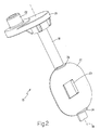
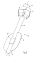
- figures 2 and 3 are two perspective views of a part of a butterfly choke valve in figure 1; and
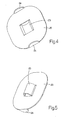
- figures 4 and 5 are two prospective views of a butterfly valve plate of the butterfly choke valve in figures 2 and 3.
- In figure 1,
numeral 1 indicates as a whole an internal combustion engine provided with four cylinders 2 (only one of which is shown in figure 1), each of which is connected to an intake manifold 3 by means of two intake valves 4 (only one of which is shown in figure 1) and to anexhaust manifold 5 by means of two exhaust valves 6 (only one of which is shown in figure 1). - Intake manifold 3 receives fresh air (i.e. air from the external environment) through a feeding pipe 7 regulated by a
butterfly valve 8 and is connected tocylinders 2 by means of corresponding intake pipes 9 (only one of which is shown in figure 1), each of which comprises two reciprocallyparallel channels 10 and is regulated by corresponding intake valves 4. Similarly,exhaust manifold 5 is connected tocylinders 2 by means of corresponding exhaust conduits 11 (only one of which is shown in figure 1), each of which is regulated by corresponding exhaust valves 6; anemission pipe 12, which ends with a muffler (known and not shown) to emit the gases produced by combustion into the atmosphere departs fromexhaust manifold 5. - According to a preferred embodiment, the fuel (e.g. petrol, diesel, methane or LPG) is injected within each
intake pipe 9 by means of acorresponding injector 13 arranged near corresponding intake valves 4. According to a different embodiment (not shown),injectors 13 are arranged so as to directly inject the fuel within eachcylinder 2. - Intake manifold 3 comprises a
swirl system 14, which is adapted to vary the introduction section of the air ofintake pipes 9 during the operation ofengine 1 according to the speed ofengine 1 itself. Specifically,swirl system 14 comprises for each intake pipe 9 achoke valve 15, which is mounted along one of the twochannels 10 ofintake conduit 9 and is adapted to vary the air introduction section throughchannel 10 itself; specifically, eachchoke valve 15 is mobile between a closed position in which it fully closeschannel 10 and a maximum opening position. - Preferably,
swirl system 14 comprises a single actuator device 16 of the electronic or pneumatic type, which simultaneously and synchronously displaces all fourchoke valves 15. Actuator device 16 comprises an electrical motor (according to a different embodiment, the motor is either pneumatic or hydraulic), which controls the displacement of a bar between two limit positions corresponding to the closed and maximum opening positions of thechoke valves 15; the bar is mechanically connected to all fourchoke valves 15 so as to simultaneously and synchronously displace allchoke valves 15 themselves. - As shown in figures 2 and 3, each
butterfly choke valve 15 comprises ashaft 18, which is rotationally mounted about arotation axis 19 under the bias of actuating device 16 and supports abutterfly valve plate 20 adapted to fluid-tightly close achannel 10 of anintake conduit 9. Preferably, eachbutterfly valve plate 20 is rigidly connected toshaft 18 by welding; alternatively, eachbutterfly valve plate 20 may be rigidly connected toshaft 18 by means of screws. - Each
butterfly choke valve 15 further comprises afastening flange 21, which is fitted ontoshaft 18 and made integral withshaft 18 itself. Fasteningflange 21 displays aconnection pin 22, which is eccentrically mounted with respect torotation axis 19 and achieves the mechanical connection between the bar of actuator device 16 andshaft 18 ofbutterfly choke valve 15 to transmit motion from actuator device 16 tobutterfly choke valve 15 itself. - Each
butterfly valve plate 20 comprises aseat 23, which is coaxially arranged with respect toshaft 18 and accommodatesshaft 18 within itself. According to a preferred embodiment shown in the accompanying figures, eachseat 23 displays a closed semicircular shape; alternatively, eachseat 23 could display a centrally open semicircular shape. - The function of each
seat 23 is to maintainbutterfly valve plate 20 in contact withshaft 18 in case of breakage of the connection (welding or screws) betweenbutterfly valve plate 20 andshaft 18 itself. In this manner, in case of breakage of the connection (welding or screws) betweenbutterfly valve plate 20 andshaft 18,butterfly valve plate 20 remains in contact withshaft 18 and cannot fall alongintake channel 10. - Preferably, each
butterfly valve plate 20 comprises twocentring elements 24, which are perpendicularly arranged with respect tobutterfly valve plate 20, display a semicircular shape, and are coaxially arranged with respect torotation axis 19 at two opposite ends ofbutterfly valve plate 20. - Each
butterfly valve plate 20 is slightly smaller thancorresponding intake channel 10 becausebutterfly valve plate 20 must be free to turn withinintake channel 10; furthermore, the difference of dimension between eachbutterfly valve plate 20 andcorresponding intake channel 10 must be such to avoid any mechanical interference also considering the inevitable construction tolerances ofbutterfly valve plate 20 and ofintake channel 10. In some cases, a certain introduction gap between eachbutterfly valve plate 20 andcorresponding intake channel 10 is also required by the engine manufacturer in project specifications. - The dimensional difference described above between each
butterfly valve plate 20 andcorresponding intake channel 10 normally determines a certain uncertainty about the axial position ofbutterfly valve plate 20 withincorresponding intake channel 10; the function ofcentring elements 24 is to determine a certain axial position ofbutterfly valve plate 20 withincorresponding intake channel 10. - Preferably, each
butterfly valve plate 20 is made by pressing a metal sheet; the manufacturing on eachbutterfly valve plate 20 of bothseat 23 andcentring elements 24 is performed at the same time as the pressing ofbutterfly valve plate 20 from the metal sheet by appropriately shaping the die. Consequently, the manufacturing on eachbutterfly valve plate 20 of bothseat 23 andcentring elements 24 is fast and cost-effective and does not imply any increase of cost with respect to a standardbutterfly valve plate 20. Specifically, the manufacturing of eachseat 23 contemplates to cutbutterfly valve plate 20 along at least two cutting lines perpendicularly arranged torotation axis 19 and to locally deformbutterfly valve plate 20 between the two cutting lines. - Subsequently, each
shaft 18 is inserted withinseat 23 of correspondingbutterfly valve plate 20 andbutterfly valve plate 20 is rigidly connected to shaft 18 (by welding or by means of screws). - Each
butterfly choke valve 15 described above displays a number of advantages, because it allows to maintainbutterfly valve plate 20 in contact withshaft 18 in the case of breakage of the connection (welding or screws) betweenbutterfly valve plate 20 andshaft 18 itself. Furthermore, thanks to the presence ofcentring elements 24, the axial position ofbutterfly valve plate 20 is determined in a certain manner withincorresponding intake channel 10. Finally, the manufacturing of eachbutterfly choke valve 15 described above is very cost-effective because, as mentioned above, no increase of cost with respect to astandard choke valve 15 is implied.
Claims (8)
- A butterfly valve (15) of a swirl system (14) for an internal combustion engine (1); the butterfly valve (15) comprises:a shaft (18) which is rotationally mounted within an intake channel (10) to rotate about a rotation axis (19); anda butterfly valve plate (20) which is rigidly connected to the shaft (18);the butterfly valve (15) is characterised in that the butterfly valve plate (20) comprises a seat (23), which is coaxially arranged with respect to the shaft (18) and accommodates the shaft (18) within itself.
- A butterfly valve (15) according to claim 1, wherein the seat (23) displays a closed semicircular shape.
- A butterfly valve (15) according to claim 1, wherein the seat (23) displays a centrally open semicircular shape.
- A butterfly valve (15) according to claim 1, 2 or 3, wherein the butterfly valve plate (20) comprises two centring elements (24), which are perpendicularly arranged with respect to the butterfly valve plate (20), display a semicircular shape, and are coaxially arranged to the rotation axis (19) at two opposite ends of the butterfly valve plate (20).
- A butterfly valve (15) of a swirl system (14) for an internal combustion engine (1); the butterfly valve (15) comprises:a shaft (18) which is rotationally mounted within an intake channel (10) to rotate about a rotation axis (19); anda butterfly valve plate (20) which is rigidly connected to the shaft (18);the butterfly valve (15) is characterised in that that the butterfly valve plate (20) comprises two centring elements (24), which are perpendicularly arranged with respect to the butterfly valve plate (20), display a semicircular shape, and are coaxially arranged to the rotation axis (22) at two opposite ends of the butterfly valve plate (20).
- A manufacturing method of a butterfly valve (15) of a swirl system (14) for an internal combustion engine (1); the butterfly valve (15) comprises:a shaft (18) which is rotationally mounted within an intake channel (10) to rotate about a rotation axis (19); anda butterfly valve plate (20) which is rigidly connected to the shaft (18);the method is characterised in that it comprises the steps of:manufacturing a seat (23) on the butterfly valve plate (20);fitting the shaft (18) within the seat (23); andrigidly connecting the butterfly valve plate (20) to the shaft (18).
- A method according to claim 6, wherein the step of making the seat (23) on the butterfly valve plate (20) contemplates:cutting the butterfly valve plate (20) along at least two cutting lines perpendicularly arranged to the rotation axis (22); andlocally deforming the butterfly valve plate (20) between those two cutting lines.
- A method according to claim 6 or 7, wherein the butterfly valve plate (20) is pressed from a metal sheet; the step of making the seat (23) on the butterfly valve plate (20) is performed at the same time as the pressing of the butterfly valve plate (20) from the metal sheet.
Priority Applications (9)
| Application Number | Priority Date | Filing Date | Title |
|---|---|---|---|
| PL06425789T PL1925796T3 (en) | 2006-11-21 | 2006-11-21 | A butterfly valve of a swirl system for an internal combustion engine |
| DE602006005167T DE602006005167D1 (en) | 2006-11-21 | 2006-11-21 | Throttle valve of a swirl system for an internal combustion engine |
| EP06425789A EP1925796B1 (en) | 2006-11-21 | 2006-11-21 | A butterfly valve of a swirl system for an internal combustion engine |
| PT06425789T PT1925796E (en) | 2006-11-21 | 2006-11-21 | A butterfly valve of a swirl system for an internal combustion engine |
| ES06425789T ES2321027T3 (en) | 2006-11-21 | 2006-11-21 | BUTTERFLY VALVE OF A TURBULENCE SYSTEM FOR AN INTERNAL COMBUSTION ENGINE. |
| AT06425789T ATE422610T1 (en) | 2006-11-21 | 2006-11-21 | THROTTLE VALVE OF A SWIRL SYSTEM FOR AN INTERNAL COMBUSTION ENGINE |
| US11/941,359 US7789372B2 (en) | 2006-11-21 | 2007-11-16 | Butterfly valve of a swirl system for an internal combustion engine |
| BRPI0705168-9A BRPI0705168B1 (en) | 2006-11-21 | 2007-11-21 | BUTTERFLY VALVE FROM A TURBULENCE SYSTEM FOR AN INTERNAL COMBUSTION ENGINE |
| CN2007101875049A CN101220772B (en) | 2006-11-21 | 2007-11-21 | Butterfly valve of a swirl system for an internal combustion engine |
Applications Claiming Priority (1)
| Application Number | Priority Date | Filing Date | Title |
|---|---|---|---|
| EP06425789A EP1925796B1 (en) | 2006-11-21 | 2006-11-21 | A butterfly valve of a swirl system for an internal combustion engine |
Publications (2)
| Publication Number | Publication Date |
|---|---|
| EP1925796A1 true EP1925796A1 (en) | 2008-05-28 |
| EP1925796B1 EP1925796B1 (en) | 2009-02-11 |
Family
ID=37945036
Family Applications (1)
| Application Number | Title | Priority Date | Filing Date |
|---|---|---|---|
| EP06425789A Not-in-force EP1925796B1 (en) | 2006-11-21 | 2006-11-21 | A butterfly valve of a swirl system for an internal combustion engine |
Country Status (9)
| Country | Link |
|---|---|
| US (1) | US7789372B2 (en) |
| EP (1) | EP1925796B1 (en) |
| CN (1) | CN101220772B (en) |
| AT (1) | ATE422610T1 (en) |
| BR (1) | BRPI0705168B1 (en) |
| DE (1) | DE602006005167D1 (en) |
| ES (1) | ES2321027T3 (en) |
| PL (1) | PL1925796T3 (en) |
| PT (1) | PT1925796E (en) |
Cited By (1)
| Publication number | Priority date | Publication date | Assignee | Title |
|---|---|---|---|---|
| WO2009129968A1 (en) * | 2008-04-22 | 2009-10-29 | Ktm Sportmotorcycle Ag | Combustion air guide device |
Families Citing this family (5)
| Publication number | Priority date | Publication date | Assignee | Title |
|---|---|---|---|---|
| EP2148077A1 (en) * | 2008-07-24 | 2010-01-27 | Magneti Marelli Powertrain S.p.A. | A suction manifold with a pneumatic actuator mechanically coupled to a shaft of a choking device by means of a rack |
| DE102010023412B4 (en) * | 2010-06-11 | 2012-05-24 | Pierburg Gmbh | Valve device for an internal combustion engine |
| CN108302206B (en) * | 2013-12-25 | 2021-07-09 | 爱三工业株式会社 | Double eccentric valve |
| DE112014006049T5 (en) * | 2013-12-25 | 2016-09-08 | Aisan Kogyo Kabushiki Kaisha | Double eccentric valve |
| CN113272540B (en) * | 2019-02-05 | 2023-06-20 | 皮尔伯格有限责任公司 | Shutter device for an internal combustion engine |
Citations (4)
| Publication number | Priority date | Publication date | Assignee | Title |
|---|---|---|---|---|
| DE10132185A1 (en) * | 2001-07-03 | 2003-01-16 | Volkswagen Ag | Internal combustion engine intake system boxes drive shafts concentrically with play freedom with exhaust return and intake integrated at metering valve. |
| EP1371832A1 (en) * | 2002-06-14 | 2003-12-17 | Robert Bosch Gmbh | Butterfly valve having overmolded axle |
| EP1408216A2 (en) * | 2002-10-09 | 2004-04-14 | Aisan Kogyo Kabushiki Kaisha | Throttle control heat dissipation device |
| DE10325196B3 (en) * | 2003-06-04 | 2005-02-10 | Pierburg Gmbh | Bypass valve for vehicle fuel unit has flow channels, switching flap and three sealing lips |
Family Cites Families (10)
| Publication number | Priority date | Publication date | Assignee | Title |
|---|---|---|---|---|
| US1517335A (en) * | 1924-12-02 | Frederick | ||
| US1230882A (en) * | 1917-03-24 | 1917-06-26 | Wrightsville Hardware Company | Damper. |
| US2529572A (en) * | 1946-01-15 | 1950-11-14 | Weatherhead Co | Carburetor valve |
| US2772850A (en) * | 1955-05-09 | 1956-12-04 | Nelson C Eaton | Flow control gate |
| US4213595A (en) * | 1978-05-04 | 1980-07-22 | Avm Corporation | Butterfly valve |
| JPS54147318A (en) * | 1978-05-12 | 1979-11-17 | Toyota Motor Corp | Exhaust gas flow control valve for internal combustion engine |
| DE3643948A1 (en) * | 1986-12-22 | 1988-06-23 | Vdo Schindling | THROTTLE VALVE CONNECTOR FOR AN INTERNAL COMBUSTION ENGINE |
| US4715581A (en) * | 1987-03-23 | 1987-12-29 | Sheet Metal Connectors, Inc. | Damper construction |
| US4967778A (en) * | 1989-10-16 | 1990-11-06 | Allied-Signal Inc. | Butterfly valve apparatus and method |
| WO2002004798A1 (en) * | 2000-07-11 | 2002-01-17 | Siemens Aktiengesellschaft | Control valve |
-
2006
- 2006-11-21 PL PL06425789T patent/PL1925796T3/en unknown
- 2006-11-21 EP EP06425789A patent/EP1925796B1/en not_active Not-in-force
- 2006-11-21 AT AT06425789T patent/ATE422610T1/en not_active IP Right Cessation
- 2006-11-21 PT PT06425789T patent/PT1925796E/en unknown
- 2006-11-21 DE DE602006005167T patent/DE602006005167D1/en active Active
- 2006-11-21 ES ES06425789T patent/ES2321027T3/en active Active
-
2007
- 2007-11-16 US US11/941,359 patent/US7789372B2/en not_active Expired - Fee Related
- 2007-11-21 BR BRPI0705168-9A patent/BRPI0705168B1/en not_active IP Right Cessation
- 2007-11-21 CN CN2007101875049A patent/CN101220772B/en not_active Expired - Fee Related
Patent Citations (4)
| Publication number | Priority date | Publication date | Assignee | Title |
|---|---|---|---|---|
| DE10132185A1 (en) * | 2001-07-03 | 2003-01-16 | Volkswagen Ag | Internal combustion engine intake system boxes drive shafts concentrically with play freedom with exhaust return and intake integrated at metering valve. |
| EP1371832A1 (en) * | 2002-06-14 | 2003-12-17 | Robert Bosch Gmbh | Butterfly valve having overmolded axle |
| EP1408216A2 (en) * | 2002-10-09 | 2004-04-14 | Aisan Kogyo Kabushiki Kaisha | Throttle control heat dissipation device |
| DE10325196B3 (en) * | 2003-06-04 | 2005-02-10 | Pierburg Gmbh | Bypass valve for vehicle fuel unit has flow channels, switching flap and three sealing lips |
Cited By (1)
| Publication number | Priority date | Publication date | Assignee | Title |
|---|---|---|---|---|
| WO2009129968A1 (en) * | 2008-04-22 | 2009-10-29 | Ktm Sportmotorcycle Ag | Combustion air guide device |
Also Published As
| Publication number | Publication date |
|---|---|
| DE602006005167D1 (en) | 2009-03-26 |
| BRPI0705168B1 (en) | 2018-07-24 |
| PT1925796E (en) | 2009-04-28 |
| EP1925796B1 (en) | 2009-02-11 |
| BRPI0705168A2 (en) | 2009-07-21 |
| ES2321027T3 (en) | 2009-06-01 |
| CN101220772B (en) | 2012-01-18 |
| US20080149876A1 (en) | 2008-06-26 |
| PL1925796T3 (en) | 2009-07-31 |
| US7789372B2 (en) | 2010-09-07 |
| ATE422610T1 (en) | 2009-02-15 |
| CN101220772A (en) | 2008-07-16 |
Similar Documents
| Publication | Publication Date | Title |
|---|---|---|
| EP1908943B1 (en) | Variable geometry intake manifold for an internal combustion engine | |
| US7789372B2 (en) | Butterfly valve of a swirl system for an internal combustion engine | |
| EP1884636B1 (en) | Variable geometry intake manifold for an internal combustion engine | |
| CN1944999B (en) | Swirl system intake manifold for an internal combustion engine | |
| US7856957B2 (en) | Intake manifold with a swirl system for an internal combustion engine | |
| US20130149114A1 (en) | Housing for a blade wheel | |
| US10738662B2 (en) | Valve arrangement and valve guide | |
| EP2148076A1 (en) | Integrated suction manifold provided with a fuel common rail | |
| EP1912011B1 (en) | Lock coupling between two mechanical components | |
| EP1950393A1 (en) | Intake manifold having a swirl system for an internal combustion engine | |
| EP2148077A1 (en) | A suction manifold with a pneumatic actuator mechanically coupled to a shaft of a choking device by means of a rack | |
| US6443134B1 (en) | Intake device for an internal combustion engine | |
| EP1916400A1 (en) | Variable geometry intake manifold with integrated actuator for an internal combustion engine | |
| US10883443B2 (en) | Integrated cylinder head fluid injection apparatus | |
| CN117469058A (en) | Exhaust gas recirculation system and automobile | |
| EP2148078A1 (en) | A suction manifold with an intermediate flange integrating the seals | |
| EP2025885A2 (en) | Oil control valve for variable cam phaser | |
| JP2015092066A (en) | Catalytic converter | |
| JP2005344517A (en) | Intake air throttling device for internal combustion engine |
Legal Events
| Date | Code | Title | Description |
|---|---|---|---|
| PUAI | Public reference made under article 153(3) epc to a published international application that has entered the european phase |
Free format text: ORIGINAL CODE: 0009012 |
|
| 17P | Request for examination filed |
Effective date: 20070806 |
|
| AK | Designated contracting states |
Kind code of ref document: A1 Designated state(s): AT BE BG CH CY CZ DE DK EE ES FI FR GB GR HU IE IS IT LI LT LU LV MC NL PL PT RO SE SI SK TR |
|
| AX | Request for extension of the european patent |
Extension state: AL BA HR MK RS |
|
| GRAP | Despatch of communication of intention to grant a patent |
Free format text: ORIGINAL CODE: EPIDOSNIGR1 |
|
| GRAS | Grant fee paid |
Free format text: ORIGINAL CODE: EPIDOSNIGR3 |
|
| GRAA | (expected) grant |
Free format text: ORIGINAL CODE: 0009210 |
|
| AKX | Designation fees paid |
Designated state(s): AT BE BG CH CY CZ DE DK EE ES FI FR GB GR HU IE IS IT LI LT LU LV MC NL PL PT RO SE SI SK TR |
|
| AK | Designated contracting states |
Kind code of ref document: B1 Designated state(s): AT BE BG CH CY CZ DE DK EE ES FI FR GB GR HU IE IS IT LI LT LU LV MC NL PL PT RO SE SI SK TR |
|
| REG | Reference to a national code |
Ref country code: GB Ref legal event code: FG4D |
|
| REG | Reference to a national code |
Ref country code: CH Ref legal event code: EP |
|
| RAP2 | Party data changed (patent owner data changed or rights of a patent transferred) |
Owner name: MAGNETI MARELLI HOLDING S.P.A. |
|
| REG | Reference to a national code |
Ref country code: IE Ref legal event code: FG4D |
|
| RAP2 | Party data changed (patent owner data changed or rights of a patent transferred) |
Owner name: MAGNETI MARELLI S.P.A. |
|
| REF | Corresponds to: |
Ref document number: 602006005167 Country of ref document: DE Date of ref document: 20090326 Kind code of ref document: P |
|
| REG | Reference to a national code |
Ref country code: PT Ref legal event code: SC4A Free format text: AVAILABILITY OF NATIONAL TRANSLATION Effective date: 20090420 |
|
| NLT2 | Nl: modifications (of names), taken from the european patent patent bulletin |
Owner name: MAGNETI MARELLI S.P.A. Effective date: 20090311 Owner name: MAGNETI MARELLI HOLDING S.P.A. Effective date: 20090304 |
|
| REG | Reference to a national code |
Ref country code: ES Ref legal event code: FG2A Ref document number: 2321027 Country of ref document: ES Kind code of ref document: T3 |
|
| REG | Reference to a national code |
Ref country code: SE Ref legal event code: TRGR |
|
| PG25 | Lapsed in a contracting state [announced via postgrant information from national office to epo] |
Ref country code: SI Free format text: LAPSE BECAUSE OF FAILURE TO SUBMIT A TRANSLATION OF THE DESCRIPTION OR TO PAY THE FEE WITHIN THE PRESCRIBED TIME-LIMIT Effective date: 20090211 Ref country code: NL Free format text: LAPSE BECAUSE OF FAILURE TO SUBMIT A TRANSLATION OF THE DESCRIPTION OR TO PAY THE FEE WITHIN THE PRESCRIBED TIME-LIMIT Effective date: 20090211 Ref country code: FI Free format text: LAPSE BECAUSE OF FAILURE TO SUBMIT A TRANSLATION OF THE DESCRIPTION OR TO PAY THE FEE WITHIN THE PRESCRIBED TIME-LIMIT Effective date: 20090211 Ref country code: LT Free format text: LAPSE BECAUSE OF FAILURE TO SUBMIT A TRANSLATION OF THE DESCRIPTION OR TO PAY THE FEE WITHIN THE PRESCRIBED TIME-LIMIT Effective date: 20090211 |
|
| REG | Reference to a national code |
Ref country code: PL Ref legal event code: T3 |
|
| NLV1 | Nl: lapsed or annulled due to failure to fulfill the requirements of art. 29p and 29m of the patents act | ||
| PG25 | Lapsed in a contracting state [announced via postgrant information from national office to epo] |
Ref country code: IS Free format text: LAPSE BECAUSE OF FAILURE TO SUBMIT A TRANSLATION OF THE DESCRIPTION OR TO PAY THE FEE WITHIN THE PRESCRIBED TIME-LIMIT Effective date: 20090611 Ref country code: AT Free format text: LAPSE BECAUSE OF FAILURE TO SUBMIT A TRANSLATION OF THE DESCRIPTION OR TO PAY THE FEE WITHIN THE PRESCRIBED TIME-LIMIT Effective date: 20090211 Ref country code: LV Free format text: LAPSE BECAUSE OF FAILURE TO SUBMIT A TRANSLATION OF THE DESCRIPTION OR TO PAY THE FEE WITHIN THE PRESCRIBED TIME-LIMIT Effective date: 20090211 |
|
| PG25 | Lapsed in a contracting state [announced via postgrant information from national office to epo] |
Ref country code: BE Free format text: LAPSE BECAUSE OF FAILURE TO SUBMIT A TRANSLATION OF THE DESCRIPTION OR TO PAY THE FEE WITHIN THE PRESCRIBED TIME-LIMIT Effective date: 20090211 |
|
| PG25 | Lapsed in a contracting state [announced via postgrant information from national office to epo] |
Ref country code: CZ Free format text: LAPSE BECAUSE OF FAILURE TO SUBMIT A TRANSLATION OF THE DESCRIPTION OR TO PAY THE FEE WITHIN THE PRESCRIBED TIME-LIMIT Effective date: 20090211 Ref country code: DK Free format text: LAPSE BECAUSE OF FAILURE TO SUBMIT A TRANSLATION OF THE DESCRIPTION OR TO PAY THE FEE WITHIN THE PRESCRIBED TIME-LIMIT Effective date: 20090211 Ref country code: EE Free format text: LAPSE BECAUSE OF FAILURE TO SUBMIT A TRANSLATION OF THE DESCRIPTION OR TO PAY THE FEE WITHIN THE PRESCRIBED TIME-LIMIT Effective date: 20090211 |
|
| PG25 | Lapsed in a contracting state [announced via postgrant information from national office to epo] |
Ref country code: RO Free format text: LAPSE BECAUSE OF FAILURE TO SUBMIT A TRANSLATION OF THE DESCRIPTION OR TO PAY THE FEE WITHIN THE PRESCRIBED TIME-LIMIT Effective date: 20090211 Ref country code: SK Free format text: LAPSE BECAUSE OF FAILURE TO SUBMIT A TRANSLATION OF THE DESCRIPTION OR TO PAY THE FEE WITHIN THE PRESCRIBED TIME-LIMIT Effective date: 20090211 |
|
| PLBE | No opposition filed within time limit |
Free format text: ORIGINAL CODE: 0009261 |
|
| STAA | Information on the status of an ep patent application or granted ep patent |
Free format text: STATUS: NO OPPOSITION FILED WITHIN TIME LIMIT |
|
| 26N | No opposition filed |
Effective date: 20091112 |
|
| PG25 | Lapsed in a contracting state [announced via postgrant information from national office to epo] |
Ref country code: BG Free format text: LAPSE BECAUSE OF FAILURE TO SUBMIT A TRANSLATION OF THE DESCRIPTION OR TO PAY THE FEE WITHIN THE PRESCRIBED TIME-LIMIT Effective date: 20090511 |
|
| PGFP | Annual fee paid to national office [announced via postgrant information from national office to epo] |
Ref country code: ES Payment date: 20091106 Year of fee payment: 4 Ref country code: SE Payment date: 20091027 Year of fee payment: 4 |
|
| PGFP | Annual fee paid to national office [announced via postgrant information from national office to epo] |
Ref country code: PT Payment date: 20091110 Year of fee payment: 4 |
|
| PG25 | Lapsed in a contracting state [announced via postgrant information from national office to epo] |
Ref country code: MC Free format text: LAPSE BECAUSE OF NON-PAYMENT OF DUE FEES Effective date: 20091130 |
|
| REG | Reference to a national code |
Ref country code: IE Ref legal event code: MM4A |
|
| PG25 | Lapsed in a contracting state [announced via postgrant information from national office to epo] |
Ref country code: GR Free format text: LAPSE BECAUSE OF FAILURE TO SUBMIT A TRANSLATION OF THE DESCRIPTION OR TO PAY THE FEE WITHIN THE PRESCRIBED TIME-LIMIT Effective date: 20090512 Ref country code: IE Free format text: LAPSE BECAUSE OF NON-PAYMENT OF DUE FEES Effective date: 20091121 |
|
| PG25 | Lapsed in a contracting state [announced via postgrant information from national office to epo] |
Ref country code: LU Free format text: LAPSE BECAUSE OF NON-PAYMENT OF DUE FEES Effective date: 20091121 |
|
| REG | Reference to a national code |
Ref country code: PT Ref legal event code: MM4A Free format text: LAPSE DUE TO NON-PAYMENT OF FEES Effective date: 20110523 |
|
| REG | Reference to a national code |
Ref country code: SE Ref legal event code: EUG |
|
| PG25 | Lapsed in a contracting state [announced via postgrant information from national office to epo] |
Ref country code: HU Free format text: LAPSE BECAUSE OF FAILURE TO SUBMIT A TRANSLATION OF THE DESCRIPTION OR TO PAY THE FEE WITHIN THE PRESCRIBED TIME-LIMIT Effective date: 20090812 |
|
| REG | Reference to a national code |
Ref country code: CH Ref legal event code: PL |
|
| GBPC | Gb: european patent ceased through non-payment of renewal fee |
Effective date: 20101121 |
|
| PG25 | Lapsed in a contracting state [announced via postgrant information from national office to epo] |
Ref country code: CH Free format text: LAPSE BECAUSE OF NON-PAYMENT OF DUE FEES Effective date: 20101130 Ref country code: LI Free format text: LAPSE BECAUSE OF NON-PAYMENT OF DUE FEES Effective date: 20101130 Ref country code: PT Free format text: LAPSE BECAUSE OF NON-PAYMENT OF DUE FEES Effective date: 20110523 |
|
| PG25 | Lapsed in a contracting state [announced via postgrant information from national office to epo] |
Ref country code: TR Free format text: LAPSE BECAUSE OF FAILURE TO SUBMIT A TRANSLATION OF THE DESCRIPTION OR TO PAY THE FEE WITHIN THE PRESCRIBED TIME-LIMIT Effective date: 20090211 |
|
| PG25 | Lapsed in a contracting state [announced via postgrant information from national office to epo] |
Ref country code: SE Free format text: LAPSE BECAUSE OF NON-PAYMENT OF DUE FEES Effective date: 20101122 Ref country code: CY Free format text: LAPSE BECAUSE OF FAILURE TO SUBMIT A TRANSLATION OF THE DESCRIPTION OR TO PAY THE FEE WITHIN THE PRESCRIBED TIME-LIMIT Effective date: 20090211 |
|
| PG25 | Lapsed in a contracting state [announced via postgrant information from national office to epo] |
Ref country code: GB Free format text: LAPSE BECAUSE OF NON-PAYMENT OF DUE FEES Effective date: 20101121 |
|
| REG | Reference to a national code |
Ref country code: ES Ref legal event code: FD2A Effective date: 20120110 |
|
| PG25 | Lapsed in a contracting state [announced via postgrant information from national office to epo] |
Ref country code: ES Free format text: LAPSE BECAUSE OF NON-PAYMENT OF DUE FEES Effective date: 20101122 |
|
| REG | Reference to a national code |
Ref country code: FR Ref legal event code: PLFP Year of fee payment: 10 |
|
| REG | Reference to a national code |
Ref country code: FR Ref legal event code: PLFP Year of fee payment: 11 |
|
| PGFP | Annual fee paid to national office [announced via postgrant information from national office to epo] |
Ref country code: PL Payment date: 20161025 Year of fee payment: 11 |
|
| REG | Reference to a national code |
Ref country code: FR Ref legal event code: PLFP Year of fee payment: 12 |
|
| REG | Reference to a national code |
Ref country code: FR Ref legal event code: PLFP Year of fee payment: 13 |
|
| PG25 | Lapsed in a contracting state [announced via postgrant information from national office to epo] |
Ref country code: PL Free format text: LAPSE BECAUSE OF NON-PAYMENT OF DUE FEES Effective date: 20171121 |
|
| PGFP | Annual fee paid to national office [announced via postgrant information from national office to epo] |
Ref country code: DE Payment date: 20191021 Year of fee payment: 14 |
|
| PGFP | Annual fee paid to national office [announced via postgrant information from national office to epo] |
Ref country code: IT Payment date: 20191021 Year of fee payment: 14 Ref country code: FR Payment date: 20191022 Year of fee payment: 14 |
|
| REG | Reference to a national code |
Ref country code: DE Ref legal event code: R119 Ref document number: 602006005167 Country of ref document: DE |
|
| PG25 | Lapsed in a contracting state [announced via postgrant information from national office to epo] |
Ref country code: IT Free format text: LAPSE BECAUSE OF NON-PAYMENT OF DUE FEES Effective date: 20201121 Ref country code: FR Free format text: LAPSE BECAUSE OF NON-PAYMENT OF DUE FEES Effective date: 20201130 |
|
| PG25 | Lapsed in a contracting state [announced via postgrant information from national office to epo] |
Ref country code: DE Free format text: LAPSE BECAUSE OF NON-PAYMENT OF DUE FEES Effective date: 20210601 |