EP1925489A1 - Instrument panel for automotive vehicles - Google Patents
Instrument panel for automotive vehicles Download PDFInfo
- Publication number
- EP1925489A1 EP1925489A1 EP07380311A EP07380311A EP1925489A1 EP 1925489 A1 EP1925489 A1 EP 1925489A1 EP 07380311 A EP07380311 A EP 07380311A EP 07380311 A EP07380311 A EP 07380311A EP 1925489 A1 EP1925489 A1 EP 1925489A1
- Authority
- EP
- European Patent Office
- Prior art keywords
- opening
- cover
- panel
- duct
- display
- Prior art date
- Legal status (The legal status is an assumption and is not a legal conclusion. Google has not performed a legal analysis and makes no representation as to the accuracy of the status listed.)
- Granted
Links
Images

Classifications
-
- B—PERFORMING OPERATIONS; TRANSPORTING
- B60—VEHICLES IN GENERAL
- B60K—ARRANGEMENT OR MOUNTING OF PROPULSION UNITS OR OF TRANSMISSIONS IN VEHICLES; ARRANGEMENT OR MOUNTING OF PLURAL DIVERSE PRIME-MOVERS IN VEHICLES; AUXILIARY DRIVES FOR VEHICLES; INSTRUMENTATION OR DASHBOARDS FOR VEHICLES; ARRANGEMENTS IN CONNECTION WITH COOLING, AIR INTAKE, GAS EXHAUST OR FUEL SUPPLY OF PROPULSION UNITS IN VEHICLES
- B60K35/00—Instruments specially adapted for vehicles; Arrangement of instruments in or on vehicles
- B60K35/50—Instruments characterised by their means of attachment to or integration in the vehicle
-
- B—PERFORMING OPERATIONS; TRANSPORTING
- B60—VEHICLES IN GENERAL
- B60K—ARRANGEMENT OR MOUNTING OF PROPULSION UNITS OR OF TRANSMISSIONS IN VEHICLES; ARRANGEMENT OR MOUNTING OF PLURAL DIVERSE PRIME-MOVERS IN VEHICLES; AUXILIARY DRIVES FOR VEHICLES; INSTRUMENTATION OR DASHBOARDS FOR VEHICLES; ARRANGEMENTS IN CONNECTION WITH COOLING, AIR INTAKE, GAS EXHAUST OR FUEL SUPPLY OF PROPULSION UNITS IN VEHICLES
- B60K37/00—Dashboards
- B60K37/20—Dashboard panels
-
- B—PERFORMING OPERATIONS; TRANSPORTING
- B60—VEHICLES IN GENERAL
- B60K—ARRANGEMENT OR MOUNTING OF PROPULSION UNITS OR OF TRANSMISSIONS IN VEHICLES; ARRANGEMENT OR MOUNTING OF PLURAL DIVERSE PRIME-MOVERS IN VEHICLES; AUXILIARY DRIVES FOR VEHICLES; INSTRUMENTATION OR DASHBOARDS FOR VEHICLES; ARRANGEMENTS IN CONNECTION WITH COOLING, AIR INTAKE, GAS EXHAUST OR FUEL SUPPLY OF PROPULSION UNITS IN VEHICLES
- B60K2360/00—Indexing scheme associated with groups B60K35/00 or B60K37/00 relating to details of instruments or dashboards
- B60K2360/60—Structural details of dashboards or instruments
- B60K2360/65—Features of dashboards
- B60K2360/658—Dashboard parts used as air ducts
-
- B—PERFORMING OPERATIONS; TRANSPORTING
- B60—VEHICLES IN GENERAL
- B60K—ARRANGEMENT OR MOUNTING OF PROPULSION UNITS OR OF TRANSMISSIONS IN VEHICLES; ARRANGEMENT OR MOUNTING OF PLURAL DIVERSE PRIME-MOVERS IN VEHICLES; AUXILIARY DRIVES FOR VEHICLES; INSTRUMENTATION OR DASHBOARDS FOR VEHICLES; ARRANGEMENTS IN CONNECTION WITH COOLING, AIR INTAKE, GAS EXHAUST OR FUEL SUPPLY OF PROPULSION UNITS IN VEHICLES
- B60K2360/00—Indexing scheme associated with groups B60K35/00 or B60K37/00 relating to details of instruments or dashboards
- B60K2360/60—Structural details of dashboards or instruments
- B60K2360/68—Features of instruments
- B60K2360/693—Cover plate features
Definitions
- the present invention relates to an instrument panel for automotive vehicles, and more specifically to an instrument panel with a head-up display.
- the current trend in automobile manufacture is to provide vehicles with a head-up display offering the driver at all times the values of specific functions of the vehicle, such as speed, engine revolutions, kilometers traveled, consumption, etc.
- the display For the driver to easily access the information, the display must be assembled such that it is easily visible by said driver without the driver having to distract his/her attention from driving.
- head-up displays are assembled directly on the panel, coinciding with an opening therein, having dimensions approximately equal or slightly greater than those of the display.
- the body or components of the display are housed inside the panel.
- the defrost duct runs under the panel, crossing under the opening, which is a problem for the assembly and disassembly of the display because once it is assembled, it cannot be disassembled or extracted without having previously extracted the defrost duct, and to do that the entire panel assembly must be disassembled. Due to its dimensions, the defrost duct is a hard-to-manage component which requires more work and, in short, any operation is more complicated and expensive.
- the object of the present invention is to eliminate the problems set forth by means of a panel with a head-up display, the display of which is installed such that its assembly and disassembly can be carried out very quickly and easily without needing to have to disassemble the panel or the defrost duct.
- the opening in which the display is assembled has dimensions exceeding those of said display and is located between the windshield and the steering wheel.
- the defrost duct crossing under the opening is interrupted precisely in coincidence with said opening.
- This opening is closed by means of an outer cover having a slightly larger contour, such that it will abut against the contour or edge of the opening.
- the cover reproduces the surface of the panel in the area of the opening such that it will virtually complete the surface of the panel.
- the mentioned cover has a duct section integrated in the rear part that coincides in dimensions and position with the previously mentioned interrupted duct section or portion of the defrost duct. At its end sections, this duct section integrated in the cover will support sealing joints with the adjacent sections of the defrost duct, running behind the instrument panel. With this set-up, a good seal will be obtained between the duct section integrated in the cover and the adjacent sections of the defrost duct running behind the board.
- the cover closing the opening of the board has a window in which the display is assembled.
- the cover is further provided with anchoring means for anchoring it to the contour of the opening, which means can consist of clamps assembled behind the cover and fixed by elastic deformation of a pin that can be anchored under the edge of the opening, operating like clips.
- the solution proposed by the invention is to make an opening in the panel having dimensions that are greater than those of the display, cutting the part of the defrost duct coinciding with said opening and integrating it in the cover, with dimensions and a position fitting with the end sections of the cut duct.
- the assembly of the display will thus be carried out in a simple manner because the cover must simply be coupled on the corresponding opening, the latter being fixed by the anchoring means for the anchoring thereof and with the duct section it incorporates, completing the defrost duct. To disassemble the display, it will be enough to simply act behind the panel to release the anchoring means and extracting or separating the cover.
- An advantage derived from the set-up of the panel of the invention is that it allows the defrost duct to run as close to the panel as needed, without being any drawback whatsoever for the assembly and disassembly of the display.
- Figures 1 and 2 show the instrument panel 1 of an automotive vehicle, the defrost duct running under such panel and which is referenced as 2.
- the defrost duct 2 is interrupted in coincidence with this opening 5 by means of transverse cuts of such duct.
- the opening 5 is closed by means of a cover 6, shown in Figure 3 , which will have a contour slightly exceeding that of the opening 5 and its outer surface will imitate the relief of the panel corresponding to the area of said opening 5.
- the cover 6 incorporates in its rear surface a duct section 7 coinciding with the cut or interrupted section in the defrost duct 2, under the opening 5.
- This duct section 7 will be sized and positioned such that it coincides with the adjacent sections corresponding to the cuts of the defrost duct 2.
- Duct section 7 incorporated in the cover 6 can further be provided at its end sections with gaskets 8 assuring a leak-tight closure with the end sections of duct 2.
- duct section 7 can be fixed to the cover 6 by means of pins 9 integral with said cover and lugs 10 integral with duct section 7, abutted and fixed by means of screws 11.
- Figure 5 shows how duct section 7, fixed to the cover 6, can be joined to the end sections of the duct 2, this joint being sealed by means of gasket 8.
- the cover 6 has an opening 12 sized to couple on the head-up display thereon.
- the cover 6 furthermore supports attachment means for attaching it to the panel, which means, as shown in Figure 6 , can be formed by clamps 13 fixed for example to a wall or lugs 14 of the cover 6, the clamps of which form an elastically deformable pin 15 which, once it is introduced through the opening 5 of the panel, will recover its position, the lower part resting against the contour of said opening and operating like a stop to prevent the accidental separation of the cover 6.
Landscapes
- Engineering & Computer Science (AREA)
- Chemical & Material Sciences (AREA)
- Combustion & Propulsion (AREA)
- Transportation (AREA)
- Mechanical Engineering (AREA)
- Instrument Panels (AREA)
- Vehicle Waterproofing, Decoration, And Sanitation Devices (AREA)
Abstract
Description
- The present invention relates to an instrument panel for automotive vehicles, and more specifically to an instrument panel with a head-up display.
- The current trend in automobile manufacture is to provide vehicles with a head-up display offering the driver at all times the values of specific functions of the vehicle, such as speed, engine revolutions, kilometers traveled, consumption, etc.
- For the driver to easily access the information, the display must be assembled such that it is easily visible by said driver without the driver having to distract his/her attention from driving.
- In traditional panels, head-up displays are assembled directly on the panel, coinciding with an opening therein, having dimensions approximately equal or slightly greater than those of the display. The body or components of the display are housed inside the panel. The defrost duct runs under the panel, crossing under the opening, which is a problem for the assembly and disassembly of the display because once it is assembled, it cannot be disassembled or extracted without having previously extracted the defrost duct, and to do that the entire panel assembly must be disassembled. Due to its dimensions, the defrost duct is a hard-to-manage component which requires more work and, in short, any operation is more complicated and expensive.
- The object of the present invention is to eliminate the problems set forth by means of a panel with a head-up display, the display of which is installed such that its assembly and disassembly can be carried out very quickly and easily without needing to have to disassemble the panel or the defrost duct.
- Therefore, according to the invention the opening in which the display is assembled has dimensions exceeding those of said display and is located between the windshield and the steering wheel. The defrost duct crossing under the opening is interrupted precisely in coincidence with said opening. This opening is closed by means of an outer cover having a slightly larger contour, such that it will abut against the contour or edge of the opening. The cover reproduces the surface of the panel in the area of the opening such that it will virtually complete the surface of the panel.
- The mentioned cover has a duct section integrated in the rear part that coincides in dimensions and position with the previously mentioned interrupted duct section or portion of the defrost duct. At its end sections, this duct section integrated in the cover will support sealing joints with the adjacent sections of the defrost duct, running behind the instrument panel. With this set-up, a good seal will be obtained between the duct section integrated in the cover and the adjacent sections of the defrost duct running behind the board.
- The cover closing the opening of the board has a window in which the display is assembled. The cover is further provided with anchoring means for anchoring it to the contour of the opening, which means can consist of clamps assembled behind the cover and fixed by elastic deformation of a pin that can be anchored under the edge of the opening, operating like clips.
- As can be seen, the solution proposed by the invention is to make an opening in the panel having dimensions that are greater than those of the display, cutting the part of the defrost duct coinciding with said opening and integrating it in the cover, with dimensions and a position fitting with the end sections of the cut duct.
- The assembly of the display will thus be carried out in a simple manner because the cover must simply be coupled on the corresponding opening, the latter being fixed by the anchoring means for the anchoring thereof and with the duct section it incorporates, completing the defrost duct. To disassemble the display, it will be enough to simply act behind the panel to release the anchoring means and extracting or separating the cover.
- An advantage derived from the set-up of the panel of the invention is that it allows the defrost duct to run as close to the panel as needed, without being any drawback whatsoever for the assembly and disassembly of the display.
- The arrangement of the joints between the duct section incorporated in the cover and the end sections of the duct fixed to the panel prevents losses of air from occurring in said duct, which together with the possibility of improving the path of the duct, will prevent the occurrence of problems in the air piping.
- In order to better understand the set-up and features of the panel of the invention, a more detailed description thereof is provided below with the aid of the attached drawings which show a non-limiting embodiment.
- In the drawings:
-
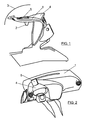
Figure 1 shows a side elevational view of a panel set up according to the invention. -
Figure 2 shows a front perspective view of the panel ofFigure 3 . -
Figure 3 shows an upper perspective view of the cover forming part of the panel of the invention. -
Figure 4 shows a cross-sectional view of the cover taken according to section line IV-IV ofFigure 3 . -
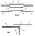
Figure 5 shows a longitudinal sectional view of the cover taken according to section line V-V ofFigure 3 . -
Figure 6 shows a partial cross-sectional view of the cover taken according to section line VI-VI ofFigure 3 . -
Figures 1 and 2 show theinstrument panel 1 of an automotive vehicle, the defrost duct running under such panel and which is referenced as 2. Anopening 5, which will have dimensions considerably exceeding those of the head-up display to be assembled, is made in this panel in the area comprised between thewindshield 3 and thevisor 4, in front of which the steering wheel is located. Thedefrost duct 2 is interrupted in coincidence with this opening 5 by means of transverse cuts of such duct. - The
opening 5 is closed by means of acover 6, shown inFigure 3 , which will have a contour slightly exceeding that of theopening 5 and its outer surface will imitate the relief of the panel corresponding to the area of saidopening 5. - The
cover 6 incorporates in its rear surface aduct section 7 coinciding with the cut or interrupted section in thedefrost duct 2, under theopening 5. Thisduct section 7 will be sized and positioned such that it coincides with the adjacent sections corresponding to the cuts of thedefrost duct 2.Duct section 7 incorporated in thecover 6 can further be provided at its end sections withgaskets 8 assuring a leak-tight closure with the end sections ofduct 2. - As can be seen in
Figure 4 ,duct section 7 can be fixed to thecover 6 by means of pins 9 integral with said cover andlugs 10 integral withduct section 7, abutted and fixed by means ofscrews 11. -
Figure 5 shows howduct section 7, fixed to thecover 6, can be joined to the end sections of theduct 2, this joint being sealed by means ofgasket 8. - As can be seen in
Figure 3 , thecover 6 has an opening 12 sized to couple on the head-up display thereon. - The
cover 6 furthermore supports attachment means for attaching it to the panel, which means, as shown inFigure 6 , can be formed byclamps 13 fixed for example to a wall orlugs 14 of thecover 6, the clamps of which form an elastically deformable pin 15 which, once it is introduced through theopening 5 of the panel, will recover its position, the lower part resting against the contour of said opening and operating like a stop to prevent the accidental separation of thecover 6. - With the discussed set-up, once the display is fixed to the
cover 6, to assemble said cover it is enough to simply position it on theopening 5 and press towards the panel, until deforming the pins 15 of theclamps 13, until reaching the position ofFigure 6 . To disassemble the cover, it is sufficient to simply act inside thepanel 1 on the pins 15, deforming them to release the stop formed against the edge of theopening 5.
Claims (3)
- An instrument panel for automotive vehicles, including a head-up display assembled in an opening made in said panel, the defrost duct running thereunder, characterized in that the mentioned opening has dimensions exceeding those of the display, is made between the windshield and the steering wheel, and the defrost duct is interrupted in coincidence with such opening; which opening is closed by means of an outer cover having a contour slightly greater than that of the opening, reproducing the surface of the panel in the area of the opening and partially integrating a duct section, coinciding in dimensions and position with the cut portion of the defrost duct; said cover having a window in which the display is assembled and anchoring means for anchoring it to the contour of the opening.
- A panel according to claim 1, characterized in that sealing joints are arranged between the end sections of the duct integrated in the cover and the adjacent sections of the defrost duct running under the panel.
- A panel according to claim 1, characterized in that the anchoring means of the cover consist of clamps assembled behind said cover and fixed by elastic deformation of a pin anchored under the edge of the opening.
Applications Claiming Priority (1)
| Application Number | Priority Date | Filing Date | Title |
|---|---|---|---|
| ES200602519U ES1064208Y (en) | 2006-11-21 | 2006-11-21 | INSTRUMENT BOARD FOR CAR VEHICLE |
Publications (2)
| Publication Number | Publication Date |
|---|---|
| EP1925489A1 true EP1925489A1 (en) | 2008-05-28 |
| EP1925489B1 EP1925489B1 (en) | 2009-09-30 |
Family
ID=38291764
Family Applications (1)
| Application Number | Title | Priority Date | Filing Date |
|---|---|---|---|
| EP07380311A Not-in-force EP1925489B1 (en) | 2006-11-21 | 2007-11-12 | Instrument panel for automotive vehicles |
Country Status (4)
| Country | Link |
|---|---|
| EP (1) | EP1925489B1 (en) |
| AT (1) | ATE444198T1 (en) |
| DE (1) | DE602007002607D1 (en) |
| ES (2) | ES1064208Y (en) |
Cited By (1)
| Publication number | Priority date | Publication date | Assignee | Title |
|---|---|---|---|---|
| US10739592B2 (en) | 2017-12-20 | 2020-08-11 | Volkswagen Aktiengesellschaft | Vehicle with a head-up display integrated into the dashboard |
Families Citing this family (1)
| Publication number | Priority date | Publication date | Assignee | Title |
|---|---|---|---|---|
| ES1064208Y (en) * | 2006-11-21 | 2007-05-16 | Seat Sa | INSTRUMENT BOARD FOR CAR VEHICLE |
Citations (7)
| Publication number | Priority date | Publication date | Assignee | Title |
|---|---|---|---|---|
| US3635305A (en) * | 1968-12-17 | 1972-01-18 | Nippon Denso Co | Housing for enclosing instruments and the like to be mounted on front instrument panel of compartment of automobile |
| JPS6175025A (en) * | 1984-09-21 | 1986-04-17 | Nissan Motor Co Ltd | Vehicle display unit |
| EP0508323A1 (en) * | 1991-04-05 | 1992-10-14 | Yazaki Corporation | An automotive display apparatus |
| EP1288057A2 (en) * | 2001-08-18 | 2003-03-05 | Bayerische Motoren Werke Aktiengesellschaft | Projection apparatus for a motor vehicle |
| JP2003170761A (en) * | 2001-12-04 | 2003-06-17 | Denso Corp | Vehicle-mounted structure of head-up display |
| JP2006088823A (en) * | 2004-09-22 | 2006-04-06 | Denso Corp | Head-up display |
| ES1064208U (en) * | 2006-11-21 | 2007-02-16 | Seat, S.A. | INSTRUMENT BOARD FOR CAR VEHICLE. |
-
2006
- 2006-11-21 ES ES200602519U patent/ES1064208Y/en not_active Expired - Fee Related
-
2007
- 2007-11-12 AT AT07380311T patent/ATE444198T1/en not_active IP Right Cessation
- 2007-11-12 EP EP07380311A patent/EP1925489B1/en not_active Not-in-force
- 2007-11-12 ES ES07380311T patent/ES2334171T3/en active Active
- 2007-11-12 DE DE602007002607T patent/DE602007002607D1/en active Active
Patent Citations (7)
| Publication number | Priority date | Publication date | Assignee | Title |
|---|---|---|---|---|
| US3635305A (en) * | 1968-12-17 | 1972-01-18 | Nippon Denso Co | Housing for enclosing instruments and the like to be mounted on front instrument panel of compartment of automobile |
| JPS6175025A (en) * | 1984-09-21 | 1986-04-17 | Nissan Motor Co Ltd | Vehicle display unit |
| EP0508323A1 (en) * | 1991-04-05 | 1992-10-14 | Yazaki Corporation | An automotive display apparatus |
| EP1288057A2 (en) * | 2001-08-18 | 2003-03-05 | Bayerische Motoren Werke Aktiengesellschaft | Projection apparatus for a motor vehicle |
| JP2003170761A (en) * | 2001-12-04 | 2003-06-17 | Denso Corp | Vehicle-mounted structure of head-up display |
| JP2006088823A (en) * | 2004-09-22 | 2006-04-06 | Denso Corp | Head-up display |
| ES1064208U (en) * | 2006-11-21 | 2007-02-16 | Seat, S.A. | INSTRUMENT BOARD FOR CAR VEHICLE. |
Cited By (1)
| Publication number | Priority date | Publication date | Assignee | Title |
|---|---|---|---|---|
| US10739592B2 (en) | 2017-12-20 | 2020-08-11 | Volkswagen Aktiengesellschaft | Vehicle with a head-up display integrated into the dashboard |
Also Published As
| Publication number | Publication date |
|---|---|
| ES1064208U (en) | 2007-02-16 |
| EP1925489B1 (en) | 2009-09-30 |
| DE602007002607D1 (en) | 2009-11-12 |
| ATE444198T1 (en) | 2009-10-15 |
| ES1064208Y (en) | 2007-05-16 |
| ES2334171T3 (en) | 2010-03-05 |
Similar Documents
| Publication | Publication Date | Title |
|---|---|---|
| JP4476118B2 (en) | Cowl top cover | |
| CN1116997C (en) | Vehicles including door seals | |
| WO2008051903A3 (en) | Flush mounted plastic window for vehicles | |
| EP1800971B1 (en) | Instrument dashboard panel structure with passenger airbag unit | |
| EP1925489B1 (en) | Instrument panel for automotive vehicles | |
| JP2019069739A (en) | Cowl grill structure for vehicle | |
| WO2008152293A3 (en) | Dashboard seal | |
| CN108216037B (en) | Vehicle mirror assembly | |
| US6209906B1 (en) | Cover for a vehicle airbag assembly | |
| US20150102638A1 (en) | Assembly for a vehicle and a method of assembling the vehicle | |
| JP5966190B2 (en) | Vehicle front structure | |
| JP7132189B2 (en) | Vehicle interior materials | |
| CN211809416U (en) | Plaque assembly in car A stand | |
| JP2007196749A (en) | Windshield structure for vehicle | |
| US20240092263A1 (en) | Housing for a rear view element of a rear view device for a vehicle | |
| EP1923264A2 (en) | Outside luminous indicator for automotive vehicles | |
| JP3812086B2 (en) | Air conditioner for automobile | |
| JP2002012061A (en) | Cluster module | |
| JP2004074816A (en) | Vehicle air conditioner | |
| JP4145784B2 (en) | Instrument panel structure for vehicles | |
| ATE516182T1 (en) | FASTENING ARRANGEMENT FOR A REAR WINDOW WIPER ON A VEHICLE | |
| JP5129038B2 (en) | Air blowout structure for vehicles | |
| JP2006082675A (en) | Mounting structure of instrument panel for vehicle | |
| RU2381923C2 (en) | Wiper | |
| JPH09156431A (en) | Fitting structure for dash silencer |
Legal Events
| Date | Code | Title | Description |
|---|---|---|---|
| PUAI | Public reference made under article 153(3) epc to a published international application that has entered the european phase |
Free format text: ORIGINAL CODE: 0009012 |
|
| AK | Designated contracting states |
Kind code of ref document: A1 Designated state(s): AT BE BG CH CY CZ DE DK EE ES FI FR GB GR HU IE IS IT LI LT LU LV MC MT NL PL PT RO SE SI SK TR |
|
| AX | Request for extension of the european patent |
Extension state: AL BA HR MK RS |
|
| 17P | Request for examination filed |
Effective date: 20081112 |
|
| AKX | Designation fees paid |
Designated state(s): AT BE BG CH CY CZ DE DK EE ES FI FR GB GR HU IE IS IT LI LT LU LV MC MT NL PL PT RO SE SI SK TR |
|
| 17Q | First examination report despatched |
Effective date: 20081215 |
|
| GRAP | Despatch of communication of intention to grant a patent |
Free format text: ORIGINAL CODE: EPIDOSNIGR1 |
|
| GRAS | Grant fee paid |
Free format text: ORIGINAL CODE: EPIDOSNIGR3 |
|
| GRAA | (expected) grant |
Free format text: ORIGINAL CODE: 0009210 |
|
| AK | Designated contracting states |
Kind code of ref document: B1 Designated state(s): AT BE BG CH CY CZ DE DK EE ES FI FR GB GR HU IE IS IT LI LT LU LV MC MT NL PL PT RO SE SI SK TR |
|
| REG | Reference to a national code |
Ref country code: CH Ref legal event code: EP Ref country code: GB Ref legal event code: FG4D |
|
| REG | Reference to a national code |
Ref country code: IE Ref legal event code: FG4D |
|
| REF | Corresponds to: |
Ref document number: 602007002607 Country of ref document: DE Date of ref document: 20091112 Kind code of ref document: P |
|
| PG25 | Lapsed in a contracting state [announced via postgrant information from national office to epo] |
Ref country code: FI Free format text: LAPSE BECAUSE OF FAILURE TO SUBMIT A TRANSLATION OF THE DESCRIPTION OR TO PAY THE FEE WITHIN THE PRESCRIBED TIME-LIMIT Effective date: 20090930 Ref country code: LT Free format text: LAPSE BECAUSE OF FAILURE TO SUBMIT A TRANSLATION OF THE DESCRIPTION OR TO PAY THE FEE WITHIN THE PRESCRIBED TIME-LIMIT Effective date: 20090930 Ref country code: SE Free format text: LAPSE BECAUSE OF FAILURE TO SUBMIT A TRANSLATION OF THE DESCRIPTION OR TO PAY THE FEE WITHIN THE PRESCRIBED TIME-LIMIT Effective date: 20090930 |
|
| LTIE | Lt: invalidation of european patent or patent extension |
Effective date: 20090930 |
|
| PG25 | Lapsed in a contracting state [announced via postgrant information from national office to epo] |
Ref country code: SI Free format text: LAPSE BECAUSE OF FAILURE TO SUBMIT A TRANSLATION OF THE DESCRIPTION OR TO PAY THE FEE WITHIN THE PRESCRIBED TIME-LIMIT Effective date: 20090930 Ref country code: LV Free format text: LAPSE BECAUSE OF FAILURE TO SUBMIT A TRANSLATION OF THE DESCRIPTION OR TO PAY THE FEE WITHIN THE PRESCRIBED TIME-LIMIT Effective date: 20090930 Ref country code: PL Free format text: LAPSE BECAUSE OF FAILURE TO SUBMIT A TRANSLATION OF THE DESCRIPTION OR TO PAY THE FEE WITHIN THE PRESCRIBED TIME-LIMIT Effective date: 20090930 |
|
| NLV1 | Nl: lapsed or annulled due to failure to fulfill the requirements of art. 29p and 29m of the patents act | ||
| REG | Reference to a national code |
Ref country code: ES Ref legal event code: FG2A Ref document number: 2334171 Country of ref document: ES Kind code of ref document: T3 |
|
| PG25 | Lapsed in a contracting state [announced via postgrant information from national office to epo] |
Ref country code: EE Free format text: LAPSE BECAUSE OF FAILURE TO SUBMIT A TRANSLATION OF THE DESCRIPTION OR TO PAY THE FEE WITHIN THE PRESCRIBED TIME-LIMIT Effective date: 20090930 Ref country code: RO Free format text: LAPSE BECAUSE OF FAILURE TO SUBMIT A TRANSLATION OF THE DESCRIPTION OR TO PAY THE FEE WITHIN THE PRESCRIBED TIME-LIMIT Effective date: 20090930 Ref country code: IS Free format text: LAPSE BECAUSE OF FAILURE TO SUBMIT A TRANSLATION OF THE DESCRIPTION OR TO PAY THE FEE WITHIN THE PRESCRIBED TIME-LIMIT Effective date: 20100130 Ref country code: PT Free format text: LAPSE BECAUSE OF FAILURE TO SUBMIT A TRANSLATION OF THE DESCRIPTION OR TO PAY THE FEE WITHIN THE PRESCRIBED TIME-LIMIT Effective date: 20100201 Ref country code: CZ Free format text: LAPSE BECAUSE OF FAILURE TO SUBMIT A TRANSLATION OF THE DESCRIPTION OR TO PAY THE FEE WITHIN THE PRESCRIBED TIME-LIMIT Effective date: 20090930 |
|
| PG25 | Lapsed in a contracting state [announced via postgrant information from national office to epo] |
Ref country code: SK Free format text: LAPSE BECAUSE OF FAILURE TO SUBMIT A TRANSLATION OF THE DESCRIPTION OR TO PAY THE FEE WITHIN THE PRESCRIBED TIME-LIMIT Effective date: 20090930 |
|
| PG25 | Lapsed in a contracting state [announced via postgrant information from national office to epo] |
Ref country code: AT Free format text: LAPSE BECAUSE OF FAILURE TO SUBMIT A TRANSLATION OF THE DESCRIPTION OR TO PAY THE FEE WITHIN THE PRESCRIBED TIME-LIMIT Effective date: 20090930 Ref country code: BE Free format text: LAPSE BECAUSE OF FAILURE TO SUBMIT A TRANSLATION OF THE DESCRIPTION OR TO PAY THE FEE WITHIN THE PRESCRIBED TIME-LIMIT Effective date: 20090930 Ref country code: MC Free format text: LAPSE BECAUSE OF NON-PAYMENT OF DUE FEES Effective date: 20091130 |
|
| PG25 | Lapsed in a contracting state [announced via postgrant information from national office to epo] |
Ref country code: NL Free format text: LAPSE BECAUSE OF FAILURE TO SUBMIT A TRANSLATION OF THE DESCRIPTION OR TO PAY THE FEE WITHIN THE PRESCRIBED TIME-LIMIT Effective date: 20090930 Ref country code: DK Free format text: LAPSE BECAUSE OF FAILURE TO SUBMIT A TRANSLATION OF THE DESCRIPTION OR TO PAY THE FEE WITHIN THE PRESCRIBED TIME-LIMIT Effective date: 20090930 |
|
| PLBE | No opposition filed within time limit |
Free format text: ORIGINAL CODE: 0009261 |
|
| STAA | Information on the status of an ep patent application or granted ep patent |
Free format text: STATUS: NO OPPOSITION FILED WITHIN TIME LIMIT |
|
| 26N | No opposition filed |
Effective date: 20100701 |
|
| PG25 | Lapsed in a contracting state [announced via postgrant information from national office to epo] |
Ref country code: IE Free format text: LAPSE BECAUSE OF NON-PAYMENT OF DUE FEES Effective date: 20091112 Ref country code: GR Free format text: LAPSE BECAUSE OF FAILURE TO SUBMIT A TRANSLATION OF THE DESCRIPTION OR TO PAY THE FEE WITHIN THE PRESCRIBED TIME-LIMIT Effective date: 20091231 |
|
| PGFP | Annual fee paid to national office [announced via postgrant information from national office to epo] |
Ref country code: FR Payment date: 20101126 Year of fee payment: 4 |
|
| PGFP | Annual fee paid to national office [announced via postgrant information from national office to epo] |
Ref country code: DE Payment date: 20101119 Year of fee payment: 4 |
|
| PG25 | Lapsed in a contracting state [announced via postgrant information from national office to epo] |
Ref country code: BG Free format text: LAPSE BECAUSE OF FAILURE TO SUBMIT A TRANSLATION OF THE DESCRIPTION OR TO PAY THE FEE WITHIN THE PRESCRIBED TIME-LIMIT Effective date: 20091130 |
|
| PG25 | Lapsed in a contracting state [announced via postgrant information from national office to epo] |
Ref country code: LU Free format text: LAPSE BECAUSE OF NON-PAYMENT OF DUE FEES Effective date: 20091112 Ref country code: MT Free format text: LAPSE BECAUSE OF FAILURE TO SUBMIT A TRANSLATION OF THE DESCRIPTION OR TO PAY THE FEE WITHIN THE PRESCRIBED TIME-LIMIT Effective date: 20090930 |
|
| PG25 | Lapsed in a contracting state [announced via postgrant information from national office to epo] |
Ref country code: HU Free format text: LAPSE BECAUSE OF FAILURE TO SUBMIT A TRANSLATION OF THE DESCRIPTION OR TO PAY THE FEE WITHIN THE PRESCRIBED TIME-LIMIT Effective date: 20100401 |
|
| PGFP | Annual fee paid to national office [announced via postgrant information from national office to epo] |
Ref country code: ES Payment date: 20101103 Year of fee payment: 4 |
|
| PG25 | Lapsed in a contracting state [announced via postgrant information from national office to epo] |
Ref country code: TR Free format text: LAPSE BECAUSE OF FAILURE TO SUBMIT A TRANSLATION OF THE DESCRIPTION OR TO PAY THE FEE WITHIN THE PRESCRIBED TIME-LIMIT Effective date: 20090930 |
|
| PG25 | Lapsed in a contracting state [announced via postgrant information from national office to epo] |
Ref country code: CY Free format text: LAPSE BECAUSE OF FAILURE TO SUBMIT A TRANSLATION OF THE DESCRIPTION OR TO PAY THE FEE WITHIN THE PRESCRIBED TIME-LIMIT Effective date: 20090930 |
|
| PG25 | Lapsed in a contracting state [announced via postgrant information from national office to epo] |
Ref country code: IT Free format text: LAPSE BECAUSE OF NON-PAYMENT OF DUE FEES Effective date: 20101112 |
|
| PGFP | Annual fee paid to national office [announced via postgrant information from national office to epo] |
Ref country code: IT Payment date: 20101130 Year of fee payment: 4 |
|
| REG | Reference to a national code |
Ref country code: CH Ref legal event code: PL |
|
| GBPC | Gb: european patent ceased through non-payment of renewal fee |
Effective date: 20111112 |
|
| PG25 | Lapsed in a contracting state [announced via postgrant information from national office to epo] |
Ref country code: LI Free format text: LAPSE BECAUSE OF NON-PAYMENT OF DUE FEES Effective date: 20111130 Ref country code: CH Free format text: LAPSE BECAUSE OF NON-PAYMENT OF DUE FEES Effective date: 20111130 |
|
| REG | Reference to a national code |
Ref country code: FR Ref legal event code: ST Effective date: 20120731 |
|
| PG25 | Lapsed in a contracting state [announced via postgrant information from national office to epo] |
Ref country code: IT Free format text: LAPSE BECAUSE OF NON-PAYMENT OF DUE FEES Effective date: 20111112 |
|
| REG | Reference to a national code |
Ref country code: DE Ref legal event code: R119 Ref document number: 602007002607 Country of ref document: DE Effective date: 20120601 |
|
| PG25 | Lapsed in a contracting state [announced via postgrant information from national office to epo] |
Ref country code: GB Free format text: LAPSE BECAUSE OF NON-PAYMENT OF DUE FEES Effective date: 20111112 |
|
| PG25 | Lapsed in a contracting state [announced via postgrant information from national office to epo] |
Ref country code: FR Free format text: LAPSE BECAUSE OF NON-PAYMENT OF DUE FEES Effective date: 20111130 |
|
| REG | Reference to a national code |
Ref country code: ES Ref legal event code: FD2A Effective date: 20130603 |
|
| PG25 | Lapsed in a contracting state [announced via postgrant information from national office to epo] |
Ref country code: DE Free format text: LAPSE BECAUSE OF NON-PAYMENT OF DUE FEES Effective date: 20120601 |
|
| PG25 | Lapsed in a contracting state [announced via postgrant information from national office to epo] |
Ref country code: ES Free format text: LAPSE BECAUSE OF NON-PAYMENT OF DUE FEES Effective date: 20111113 |