EP1925456A2 - Liquid-jet apparatus - Google Patents
Liquid-jet apparatus Download PDFInfo
- Publication number
- EP1925456A2 EP1925456A2 EP07254507A EP07254507A EP1925456A2 EP 1925456 A2 EP1925456 A2 EP 1925456A2 EP 07254507 A EP07254507 A EP 07254507A EP 07254507 A EP07254507 A EP 07254507A EP 1925456 A2 EP1925456 A2 EP 1925456A2
- Authority
- EP
- European Patent Office
- Prior art keywords
- liquid
- ink
- needle
- introducing
- groove portions
- Prior art date
- Legal status (The legal status is an assumption and is not a legal conclusion. Google has not performed a legal analysis and makes no representation as to the accuracy of the status listed.)
- Withdrawn
Links
- 239000007788 liquid Substances 0.000 claims abstract description 144
- 238000003860 storage Methods 0.000 claims abstract description 48
- 238000007789 sealing Methods 0.000 claims description 153
- 238000004140 cleaning Methods 0.000 abstract description 17
- 238000007599 discharging Methods 0.000 abstract description 13
- 238000003780 insertion Methods 0.000 description 57
- 230000037431 insertion Effects 0.000 description 57
- 230000002093 peripheral effect Effects 0.000 description 21
- 238000005096 rolling process Methods 0.000 description 11
- 238000004519 manufacturing process Methods 0.000 description 9
- 230000007246 mechanism Effects 0.000 description 8
- 239000004743 Polypropylene Substances 0.000 description 6
- 239000000758 substrate Substances 0.000 description 5
- 239000003086 colorant Substances 0.000 description 4
- 238000005401 electroluminescence Methods 0.000 description 4
- 229920005989 resin Polymers 0.000 description 4
- 239000011347 resin Substances 0.000 description 4
- 239000000853 adhesive Substances 0.000 description 3
- 230000008901 benefit Effects 0.000 description 3
- 230000000903 blocking effect Effects 0.000 description 3
- 238000001704 evaporation Methods 0.000 description 3
- 230000008020 evaporation Effects 0.000 description 3
- 238000001914 filtration Methods 0.000 description 3
- 239000000463 material Substances 0.000 description 3
- -1 polypropylene Polymers 0.000 description 3
- 229920001155 polypropylene Polymers 0.000 description 3
- 229910001220 stainless steel Inorganic materials 0.000 description 3
- 239000010935 stainless steel Substances 0.000 description 3
- XUIMIQQOPSSXEZ-UHFFFAOYSA-N Silicon Chemical compound [Si] XUIMIQQOPSSXEZ-UHFFFAOYSA-N 0.000 description 2
- 238000005452 bending Methods 0.000 description 2
- 230000006835 compression Effects 0.000 description 2
- 238000007906 compression Methods 0.000 description 2
- 239000013013 elastic material Substances 0.000 description 2
- 229920001971 elastomer Polymers 0.000 description 2
- 239000004973 liquid crystal related substance Substances 0.000 description 2
- 239000002184 metal Substances 0.000 description 2
- 230000000149 penetrating effect Effects 0.000 description 2
- 230000003252 repetitive effect Effects 0.000 description 2
- 229910052710 silicon Inorganic materials 0.000 description 2
- 239000010703 silicon Substances 0.000 description 2
- 238000011144 upstream manufacturing Methods 0.000 description 2
- 238000003466 welding Methods 0.000 description 2
- 238000000018 DNA microarray Methods 0.000 description 1
- 229920000181 Ethylene propylene rubber Polymers 0.000 description 1
- 229920000459 Nitrile rubber Polymers 0.000 description 1
- 238000010521 absorption reaction Methods 0.000 description 1
- 239000012298 atmosphere Substances 0.000 description 1
- 230000015572 biosynthetic process Effects 0.000 description 1
- 229920005549 butyl rubber Polymers 0.000 description 1
- 239000002131 composite material Substances 0.000 description 1
- 238000005520 cutting process Methods 0.000 description 1
- 239000000428 dust Substances 0.000 description 1
- 239000013536 elastomeric material Substances 0.000 description 1
- 238000005530 etching Methods 0.000 description 1
- 239000011344 liquid material Substances 0.000 description 1
- 238000012986 modification Methods 0.000 description 1
- 230000004048 modification Effects 0.000 description 1
- 238000012856 packing Methods 0.000 description 1
- 229920001084 poly(chloroprene) Polymers 0.000 description 1
- 239000012488 sample solution Substances 0.000 description 1
- 229920002379 silicone rubber Polymers 0.000 description 1
- 238000009751 slip forming Methods 0.000 description 1
- 229920003002 synthetic resin Polymers 0.000 description 1
- 239000000057 synthetic resin Substances 0.000 description 1
Images







Classifications
-
- B—PERFORMING OPERATIONS; TRANSPORTING
- B41—PRINTING; LINING MACHINES; TYPEWRITERS; STAMPS
- B41J—TYPEWRITERS; SELECTIVE PRINTING MECHANISMS, i.e. MECHANISMS PRINTING OTHERWISE THAN FROM A FORME; CORRECTION OF TYPOGRAPHICAL ERRORS
- B41J2/00—Typewriters or selective printing mechanisms characterised by the printing or marking process for which they are designed
- B41J2/005—Typewriters or selective printing mechanisms characterised by the printing or marking process for which they are designed characterised by bringing liquid or particles selectively into contact with a printing material
- B41J2/01—Ink jet
- B41J2/17—Ink jet characterised by ink handling
- B41J2/19—Ink jet characterised by ink handling for removing air bubbles
-
- B—PERFORMING OPERATIONS; TRANSPORTING
- B41—PRINTING; LINING MACHINES; TYPEWRITERS; STAMPS
- B41J—TYPEWRITERS; SELECTIVE PRINTING MECHANISMS, i.e. MECHANISMS PRINTING OTHERWISE THAN FROM A FORME; CORRECTION OF TYPOGRAPHICAL ERRORS
- B41J2/00—Typewriters or selective printing mechanisms characterised by the printing or marking process for which they are designed
- B41J2/005—Typewriters or selective printing mechanisms characterised by the printing or marking process for which they are designed characterised by bringing liquid or particles selectively into contact with a printing material
- B41J2/01—Ink jet
- B41J2/135—Nozzles
- B41J2/145—Arrangement thereof
-
- B—PERFORMING OPERATIONS; TRANSPORTING
- B41—PRINTING; LINING MACHINES; TYPEWRITERS; STAMPS
- B41J—TYPEWRITERS; SELECTIVE PRINTING MECHANISMS, i.e. MECHANISMS PRINTING OTHERWISE THAN FROM A FORME; CORRECTION OF TYPOGRAPHICAL ERRORS
- B41J2/00—Typewriters or selective printing mechanisms characterised by the printing or marking process for which they are designed
- B41J2/005—Typewriters or selective printing mechanisms characterised by the printing or marking process for which they are designed characterised by bringing liquid or particles selectively into contact with a printing material
- B41J2/01—Ink jet
- B41J2/135—Nozzles
- B41J2/165—Prevention or detection of nozzle clogging, e.g. cleaning, capping or moistening for nozzles
- B41J2/16585—Prevention or detection of nozzle clogging, e.g. cleaning, capping or moistening for nozzles for paper-width or non-reciprocating print heads
- B41J2/16588—Print heads movable towards the cleaning unit
-
- B—PERFORMING OPERATIONS; TRANSPORTING
- B41—PRINTING; LINING MACHINES; TYPEWRITERS; STAMPS
- B41J—TYPEWRITERS; SELECTIVE PRINTING MECHANISMS, i.e. MECHANISMS PRINTING OTHERWISE THAN FROM A FORME; CORRECTION OF TYPOGRAPHICAL ERRORS
- B41J2/00—Typewriters or selective printing mechanisms characterised by the printing or marking process for which they are designed
- B41J2/005—Typewriters or selective printing mechanisms characterised by the printing or marking process for which they are designed characterised by bringing liquid or particles selectively into contact with a printing material
- B41J2/01—Ink jet
- B41J2/17—Ink jet characterised by ink handling
- B41J2/175—Ink supply systems ; Circuit parts therefor
-
- B—PERFORMING OPERATIONS; TRANSPORTING
- B41—PRINTING; LINING MACHINES; TYPEWRITERS; STAMPS
- B41J—TYPEWRITERS; SELECTIVE PRINTING MECHANISMS, i.e. MECHANISMS PRINTING OTHERWISE THAN FROM A FORME; CORRECTION OF TYPOGRAPHICAL ERRORS
- B41J2/00—Typewriters or selective printing mechanisms characterised by the printing or marking process for which they are designed
- B41J2/005—Typewriters or selective printing mechanisms characterised by the printing or marking process for which they are designed characterised by bringing liquid or particles selectively into contact with a printing material
- B41J2/01—Ink jet
- B41J2/17—Ink jet characterised by ink handling
- B41J2/175—Ink supply systems ; Circuit parts therefor
- B41J2/17503—Ink cartridges
- B41J2/17506—Refilling of the cartridge
- B41J2/17509—Whilst mounted in the printer
-
- B—PERFORMING OPERATIONS; TRANSPORTING
- B41—PRINTING; LINING MACHINES; TYPEWRITERS; STAMPS
- B41J—TYPEWRITERS; SELECTIVE PRINTING MECHANISMS, i.e. MECHANISMS PRINTING OTHERWISE THAN FROM A FORME; CORRECTION OF TYPOGRAPHICAL ERRORS
- B41J2/00—Typewriters or selective printing mechanisms characterised by the printing or marking process for which they are designed
- B41J2/005—Typewriters or selective printing mechanisms characterised by the printing or marking process for which they are designed characterised by bringing liquid or particles selectively into contact with a printing material
- B41J2/01—Ink jet
- B41J2/17—Ink jet characterised by ink handling
- B41J2/175—Ink supply systems ; Circuit parts therefor
- B41J2/17503—Ink cartridges
- B41J2/17513—Inner structure
-
- B—PERFORMING OPERATIONS; TRANSPORTING
- B41—PRINTING; LINING MACHINES; TYPEWRITERS; STAMPS
- B41J—TYPEWRITERS; SELECTIVE PRINTING MECHANISMS, i.e. MECHANISMS PRINTING OTHERWISE THAN FROM A FORME; CORRECTION OF TYPOGRAPHICAL ERRORS
- B41J2/00—Typewriters or selective printing mechanisms characterised by the printing or marking process for which they are designed
- B41J2/005—Typewriters or selective printing mechanisms characterised by the printing or marking process for which they are designed characterised by bringing liquid or particles selectively into contact with a printing material
- B41J2/01—Ink jet
- B41J2/17—Ink jet characterised by ink handling
- B41J2/175—Ink supply systems ; Circuit parts therefor
- B41J2/17503—Ink cartridges
- B41J2/1752—Mounting within the printer
- B41J2/17523—Ink connection
-
- B—PERFORMING OPERATIONS; TRANSPORTING
- B41—PRINTING; LINING MACHINES; TYPEWRITERS; STAMPS
- B41J—TYPEWRITERS; SELECTIVE PRINTING MECHANISMS, i.e. MECHANISMS PRINTING OTHERWISE THAN FROM A FORME; CORRECTION OF TYPOGRAPHICAL ERRORS
- B41J2/00—Typewriters or selective printing mechanisms characterised by the printing or marking process for which they are designed
- B41J2/005—Typewriters or selective printing mechanisms characterised by the printing or marking process for which they are designed characterised by bringing liquid or particles selectively into contact with a printing material
- B41J2/01—Ink jet
- B41J2/17—Ink jet characterised by ink handling
- B41J2/175—Ink supply systems ; Circuit parts therefor
- B41J2/17503—Ink cartridges
- B41J2/17559—Cartridge manufacturing
Definitions
- the present invention relates to a liquid-jet apparatus such as an ink-jet recording apparatus, and more particularly relates to a liquid-jet apparatus which ejects a liquid stored in a liquid storage member from nozzle orifices in a liquid-jet head by introducing the liquid into the liquid-jet head through liquid introducing needles.
- liquid-jet apparatus which includes a liquid-jet head capable of ejecting a liquid, and which ejects various kinds of liquid from the liquid-jet head.
- a liquid-jet apparatus include, for example, an image recording apparatus such as an ink-jet printer which performs recording by ejecting ink droplets and having the droplets land on recording paper or the like as an ejection target (recording medium).
- an image recording apparatus such as an ink-jet printer which performs recording by ejecting ink droplets and having the droplets land on recording paper or the like as an ejection target (recording medium).
- the liquid-jet apparatus has been applied not only for the image recording apparatus but also for various types of manufacturing equipment.
- the liquid-jet apparatus is used for ejecting various liquid materials such as color materials and electrodes onto a pixel forming region, an electrode forming region and the like.
- the liquid-jet apparatus of this type there have been developed a wide variety of apparatuses using a cartridge-type liquid storage member that is easily distributed and handled.
- a printer those using ink cartridges filled with liquid ink have been widely used.
- the ink cartridge is loaded on a cartridge loading section and ink introducing needles (liquid introducing columnar bodies) are inserted into the ink cartridge.
- the ink in the ink cartridge is introduced into a recording head that is a kind of liquid-jet head through ink introducing ports (liquid introducing ports) which are drilled in tips (tapered portions) of the ink introducing needles.
- opening portions of needle insertion slots (ink outlets) provided in a bottom portion thereof are sealed with a thin breakable resin film (sealing film) made of PP (polypropylene) or the like.
- a thin breakable resin film made of PP (polypropylene) or the like.
- an ideal state is that ink passages (liquid passages) from the ink introducing needles to nozzle orifices in the recording head are filled with the ink.
- bubbles may enter the ink passages during replacement of the ink cartridge or the like.
- the film In this breaking of the sealing film, the film is flexed and temporarily adheres to the tips of the ink introducing needles. Accordingly, air compressed between the sealing film and the ink introducing needles in this adhesion state enters the ink introducing needles from ink introducing ports and becomes bubbles. Thereafter, the bubbles that have entered ink passages gradually grow in size and some of the overgrown bubbles are moved toward a pressure chamber by a flow of the ink. As a result, there may arise problems such as pressure loss due to absorption of pressure fluctuations in an ejection operation by the bubbles and insufficient supply of ink due to blocking of the passages by the bubbles.
- JP-A-2006-069168 is an example of related art.
- JP-A-2006-069168 is for discharging the bubbles that have entered the ink introducing needle rather than preventing the bubbles from entering the ink introducing needle.
- the invention disclosed in JP-A-2006-069168 is for discharging the bubbles that have entered the ink introducing needle rather than preventing the bubbles from entering the ink introducing needle.
- An advantage of some aspects of the invention is to provide a liquid-jet apparatus which can suppress liquid consumption by preventing air to turn into bubbles from entering a liquid introducing columnar body in replacement of a liquid storage member and thus reducing a frequency of execution of a cleaning operation for discharging the bubbles inside a liquid passage.
- An aspect of the invention to achieve the advantage is a liquid-jet apparatus including: a liquid storage member in which a liquid is stored, and which has an outlet to be an outlet of the liquid; a liquid-storage-member counting part on which the liquid storage member is detachably mounted; a liquid introducing columnar body which introduces the liquid inside the liquid storage member into a liquid passage therein from liquid introducing ports in a state of being inserted into the cutlet of the liquid storage member mounted; and a liquid-jet head which can eject the liquid, which is introduced from the liquid introducing columnar body, from nozzle orifices in accordance with the operation of a pressure generator.
- the liquid introducing columnar body includes a tip surface facing the outlet and a straight portion formed continuously with the tip surface, and groove portions are provided in the tip surface of the liquid introducing columnar body.
- the groove portions are provided in the tip surface of the liquid introducing columnar body, the tip surface facir-g a sealing member.
- the groove portions penetrate a boundary between the tip surface and the straight portion.
- the groove portions penetrate the boundary between the tip surface of the liquid introducing columnar body and the straight portion.
- the groove portions continuously extend to the middle of the straight portion from the tip surface.
- the groove portions continuously extend to the straight portion from the tip surface of the liquid introducing columnar body.
- the liquid introducing ports are drilled to have openings inside the corresponding groove portions.
- the liquid introducing ports are drilled to have openings inside the groove portions.
- liquid introducing columnar body includes a needle-like protrusion having a tapered portion whose diameter is gradually increased toward its base from its tip, and the tip surface is a tapered surface of the needle-like protrusion.
- the tip of the liquid introducing columnar body is the needle-like protrusion having the tapered portion.
- the outlet of the liquid storage member is sealed by a sealing member to be broken along one direction, and the groove portions in the liquid introducing columnar body are formed along the direction in which the sealing member is to be broken.
- an area of the groove portions covered with the sealing member can be reduced.
- a liquid-jet apparatus including: a liquid storage member in which a liquid is stored, and which has an outlet to be an outlet of the liquid; a liquid-storage-member mounting part on which the liquid storage member is detachably mounted; a liquid introducing columnar body which introduces the liquid inside the liquid storage member into a liquid passage therein from liquid introducing ports in a state of being inserted into the outlet of the liquid storage member mounted; and a liquid-jet head which can eject the liquid, which is introduced from the liquid introducing columnar body, from nozzle orifices in accordance with the operation of a pressure generator.
- the outlet of the liquid storage member is sealed by a sealing member to be broken along one direction.
- a protrusion is formed on a tip surface of the liquid introducing columnar body, the tip surface facing the sealing member, and the protrusion has its longitudinal direction intersecting with the direction in which the sealing member is to be broken.
- an area of an opening portion of the sealing member covered with the protrusion can be reduced.
- more air between the outlet of the liquid storage member and the sealing member blocking the outlet can be discharged to the outside. Therefore, in the mounting of the liquid storage member, the air to turn into bubbles can be prevented from entering the liquid introducing columnar body.
- a frequency of execution of a cleaning operation for discharging the babbles flowing into the liquid introducing columnar body to the outside can be reduced. As a result, ink consumption associated with the cleaning operation can be reduced.
- the liquid introducing columnar body has a shoulder portion continuous with a base of the protrusion, and the liquid introducing ports are drilled in the shoulder portion.
- the liquid introducing ports never directly adhere to the sealing member. Therefore, air between the sealing member and an outer surface of the shoulder portion in the liquid introducing columnar body is made less likely to be pushed directly into the liquid introducing ports. Thus, in the mounting of the liquid storage member, the air can be further prevented from entering the liquid introducing columnar body from the liquid introducing ports.
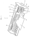
- Fig. 1 is a perspective view of a printer.
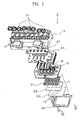
- Fig. 2 is an exploded perspective view of a recording head.
- Fig. 3 is a plan view of the recording head.
- Fig. 4 is a cross-sectional view of the recording head.
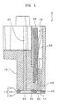
- Fig. 5 is a cross-sectional view of a main part of the recording head.
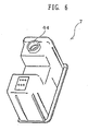
- Fig. 6 is a perspective view of an ink cartridge.
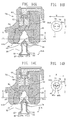
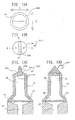
- Fig. 7A is a plan view; and Fig. 7B is a cross-sectional view showing one of ink introducing needles.
- Figs. 8A to 8C are cross-sectional views when the ink cartridge is mounted on the ink introducing needles.
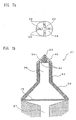
- Fig. 9A is a plan view; and Fig. 9B is a cross-sectional view showing one of ink introducing needles.
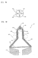
- Figs. 10A to 10C are plan views of ink introducing needles.
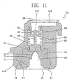
- Fig. 11 is a cross-sectional view of a needle insertion slot section in an ink cartridge.
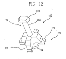
- Fig. 12 is a perspective view of a valve body in the ink cartridge.
- Fig. 13A is a plan view of a needle insertion slot
- Fig. 13B is a plan view of an ink introducing needle
- Fig. 13C is a cross-sectional view of the ink introducing needle.
- Figs. 14A and 14C are cross-sectional views showing how the ink cartridge is mounted on the ink introducing needles and Figs. 14B and 14D are plan views cf the ink introducing needle when viewed from the arrow A-A direction in Figs. 14A and 14C .
- Figs. 15A and 15C are cross-sectional views showing how the ink cartridge is mounted on the ink introducing needles and Figs . 15B and 15D are plan views of the ink introducing needle when viewed from the arrow A-A direction in Figs. 15A and 15C .
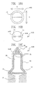
- Fig. 16A is a plan view of the needle insertionslot
- Fig. 16B is a plan view of an ink introducing needle
- Fig. 16C is a cross-sectional view of the ink introducing needle.
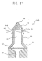
- Fig. 17 is a cross-sectional view of the ink introducing needle.
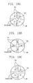
- Figs. 18A to 18C are plan views of ink introducing needles.
- Fig. 19A is a plan view of a needle insertion slot
- Fig. 19B is a plan view of an ink introducing needle
- Figs. 19C and 19D are cross-sectional views of the ink introducing needle.
- Figs. 20A and 20C are cross-sectional views when an ink cartridge is mounted on the ink introducing needles; and Figs. 20B and 20D are plan views of the ink introducing needle when viewed from the arrow A-A direction in Figs. 20A and 20C .
- Figs. 21A and 21C are cross-sectional views when the ink cartridge is mounted on the ink introducing needles; and Figs. 21B and 21D are plan views of the ink introducing needle when viewed from the arrow A-A direction in Figs. 21A and 21C .
- Fig. 1 is a perspective view of the printer typified by the ink-jet recording apparatus.
- Fig. 2 is an exploded perspective view of a recording head.
- Fig. 3 is a plan view of the recording head.
- Fig. 4 is a cross-sectional view of the recording head.
- Fig. 5 is a cross-sectional view of a main part of the recording head.
- FIG. 1 a schematic configuration of the ink-jet recording apparatus (a kind of the liquid-jet apparatus and hereinafter referred to as a printer) which has the recording head mounted thereon.
- a printer 1 shown in Fig. 1 performs recording of images and the like by ejecting ink in a form of ink droplets onto a surface of a recording medium (ejection target) 2 such as recording paper.
- the printer 1 includes: a recording head 3; a carriage 4 to which the recording head 3 is attached; a carriage moving mechanism 5 which moves the carriage 4 back and forth in a main scanning direction; a paper feed mechanism 6 which transfers the recording medium 2 in a sub-scanning direction (direction perpendicular to the main scanning direction) ; and the like.
- the ink is a kind of liquid in the invention and stored in an ink cartridge 7 (a kind of liquid storage member).
- the ink cartridge 7 is detachably loaded on the carriage 4 having the recording head 3 attached thereto.
- the carriage moving mechanism 5 includes a timing belt a This timing belt 8 is driven by a pulse motor 9 such as a DC motor. Therefore, when the pulse motor 9 is operated, the carriage 4 is guided by a guide rod 10 installed in the printer 1 and moved back and forth in the main scanning direction (width direction of the recording medium 2).
- a pulse motor 9 such as a DC motor. Therefore, when the pulse motor 9 is operated, the carriage 4 is guided by a guide rod 10 installed in the printer 1 and moved back and forth in the main scanning direction (width direction of the recording medium 2).
- a capping mechanism 12 is provided.
- the capping mechanism 12 has a tray-shaped cap member 12' which can come into contact with a. nozzle forming surface of the recording head 3.
- a space inside the cap member 12' functions as a sealing hollow part and the cap member 12' is configured to be able to adhere to the nozzle forming surface in a state of allowing a nozzle orifice 14 (see Fig. 5 ) in the recording head 3 to face the inside of the sealing hollow part.
- a pump unit 13 is connected to the capping mechanism 12 and a pressure in the sealing hollow part can be reduced by operating the pump unit 13.
- the capping mechanism 12 is configured to perform a cleaning operation for forcibly suctioning and discharging the ink and bubbles in the recording head 3 (in ink passages). In this cleaning operation, ink flows having a flow rate several times higher than that in a normal recording operation are generated in the ink passages (ink introducing paths 38) by operating the pump unit 13 in the state where the cap member 12' is allowed to adhere to the nozzle forming surface.
- bubbles floating inside an increased diameter portion 52 to be described later are put on the ink flows and allowed to pass toward a downstream side while being pressed against upper surfaces (an upstream side) of filters 19.
- the bubbles are discharged to the outside of the recording head 3 from the nozzle orifices 14 through a series of ink passages on the downstream side of the filters 19.
- the recording head 3 shown in Fig. 2 generally includes an introducing needle unit 15, a head case 16, a passage unit 17, a vibrator unit 18 and the like.
- the introducing needle unit 15 is made of, for example, synthetic resin and, as shown in Fig. 3 , a plurality of cartridge mounting parts 15' (a kind of liquid-storage-member mounting part) are provided on an upper surface whereof.
- ink introducing needles 21 (corresponding to liquid introducing columnar bodies in the invention) are attached to have their tips protrude upward in a state where the filters 19 for filtering the ink in the ink passages are interposed therebetween.
- the ink cartridge 7 having various kinds of ink stored therein is mounted.
- the ink introducing needles 21 are inserted into the ink cartridge 7.
- an ink storage space inside the ink cartridge 7 and the ink passages inside tha recording head 3 are communicated with each other through ink introducing ports 24 (see Figs. 7A and 7B ) which are drilled in tips of the ink introducing needles 21. Accordingly, the ink stored in the ink cartridge 7 is introduced into the recording head 3 through the ink introducing ports 24. Note that the ink cartridge 7 and the ink introducing needles 21 will be described in detail later.
- a circuit board 25 is attached between a lower surface of the introducing needle unit 15, the lower surface being a side opposite to the cartridge mounting parts 15' , and an upper surface of the head case 16.
- the circuit board 25 includes, for example: a circuit pattern for supplying a driving signal to a piezoelectric vibrator 26 (see Fig. 5 ); a connector for connection with the printer 1 main body; and the like.
- the circuit board 25 is attached to the introducing needle unit 15 with a sheet member 27 interposed therebetween, which functions as a packing.
- the head case 16 is a hollow box-shaped member for housing the vibrator unit 18 having the piezoelectric vibrator 26. Inside the head case 16, a housing hollow part 28 (see Fig. 5 ) is formed, which can house the vibrator unit 18 therein.
- the vibrator unit 18 is housed in the housing hollow part 28 and fixed to an inner peripheral surface of the housing hollow part 28 with an adhesive agent or the like.
- the passage unit 17 is fixed with an adhesive agent or the like to a front end surface of the head case 16, which is opposite to a surface for mounting the introducing needle unit 15.
- the passage unit 17 is prepared by bonding and integrating, with an adhesive agent or the like, a nozzle plate 30 and a vibration plate 31 while sandwiching a passage-forming substrate 29 therebetween in a laminated state where the nozzle plate 30 is disposed on one side of the passage-forming substrate 29 and the vibration plate 31 is disposed on the other side thereof that is opposite to the nozzle plate 30.
- the nozzle plate 30 is a member made of, for example, a stainless-steel thin plate.
- minute nozzle orifices 14 are formed in a row with a pitch corresponding to dot formation density of the printer 1.
- a head cover 32 is made of, for example, a thin metal plate member and is attached to a front end portion of the head case 16 to surround a peripheral portion of the nozzle plate 30 from outside thereof.
- the head cover 32 has a function of protecting the passage unit 17 and the front end portion of the head case 16 and also preventing charging of the nozzle plate 30.
- the passage-forming substrate 29 bonded to the nozzle plate 30 is, as shown in Fig. 5 , a plate-like member in which a plurality of common ink chambers 33, pressure chambers 35 and ink supply ports 34 are formed to correspond to the respective nozzle orifices 14 in a state of being separated with compartment walls.
- the common ink chambers 33 and the pressure chambers 35 are hollow parts, and the ink supply ports 34 are communicating parts which communicate those chambers with each other.
- the passage-forming substrate 29 is prepared by etching a silicon wafer, for example.
- Each of the pressure chambers 35 is formed to be a long and narrow chamber extending in a direction perpendicular to an arrangement direction of the nozzle orifices 14 (a nozzle array direction).
- each of the common ink chambers 33 is a chamber which is communicated with the ink introducing path 38 (a kind of liquid passage, see Fig. 7B ) in the ink introducing needle 21 through a head passage 37 (a kind of liquid passage) penetrating the head case 16 in its height direction and into which the ink stored in the ink cartridge 7 is introduced.
- the ink introduced into the common ink chambers 33 is supplied to the pressure chambers 35 through the respective ink supply ports 34.
- the vibration plate 31 bonded to the other side of the passage-forming substrate 29, the other side being opposite to the nozzle plate 30, is a composite plate material having a double-layered structure in which an elastic film is laminated on a supporting plate made of metal such as stainless steel.
- an island part 40 for bonding a tip of a free end of the piezoelectric vibrator 26 is formed in a portion of the vibration plate 31 corresponding to the pressure chamber 35.
- This island part functions as a diaphragm part.
- the vibration plate 31 seals an opening surface on one side of a hollow part to be the common ink chamber 33 and also functions as a compliance part. In the portion that functions as the compliance part, only the elastic film is formed.
- the vibrator unit 18 includes: a piezoelectric vibrator group 41 as pressure generation means; a fixed plate 42 to which the piezoelectric vibrator group 41 is bonded; a flexible cable (not shown) for supplying the driving signal from the circuit board 25 to the piezoelectric vibrator group 41; and the like.
- the piezoelectric vibrator group 41 in this embodiment includes a plurality of piezoelectric vibrators 26 which are arranged in a comb-teeth pattern. Each of the piezoelectric vibrators 26 has its fixed end bonded onto the fixed plate 42 and its free end protruding outside a front end surface of the fixed plate 42 .
- the piezoelectric vibrator 26 is attached onto the fixed plate 42 in a so-called cantilever state.
- the fixed plate 42 supporting the piezoelectric vibrators 26 is made of stainless steel having a thickness of about 1 mm, for example.
- an electrostatic actuator, a magnetostrictor, a heater element and the like can be used other than the piezoelectric vibrator.
- the piezoelectric vibrator 26 extends or is contracted in a longitudinal direction of the element, the island part 40 is moved in a direction approaching or separating from the pressure chamber 35.
- a volume of the pressure chamber 35 is changed to cause a pressure fluctuation in the ink inside the pressure chamber 35.
- ink droplets a kind of liquid droplets
- Fig. 6 is a perspective view showing a configuration of the ink cartridge.
- Figs. 7A and 7B are views showing a configuration of each of the ink introducing needles.
- Fig. 7A is a plan view of the ink introducing needle and
- Fig. 7B is a cross-sectional view cf the ink introducing needle, taken along the longitudinal direction thereof.
- the ink cartridge 7 is a member that functions as a kind of the liquid storage member of the invention, and in which ink to be supplied to the recording head 3 is stored.
- the printer 1 of this embodiment is configured to be able to eject eight kinds of ink, to be more specific, eight colors of ink, including yellow, magenta, cyan, matte black, photo black, red, blue and gloss optimizer (clear) .
- a needle insertion slot 44 that is an ink outlet is provided, into which the ink introducing needle 21 is to be inserted.
- This needle insertion slot 44 is formed to be a short cylindrical part from the bottom surface of the ink cartridge 7 toward the outside.
- An O-ring 45 made of an elastic material such as rubber is provided in a portion closer to a front opening on an inner circumferential surface of the cylindrical part.
- a sealing film 46 that is a kind of sealing member is attached to the front opening for sealing. This sealing film 46 is a seal for preventing leakage and evaporation of the ink stored in the ink cartridge 7 that is unused.
- the sealing film for example, a thin (a thickness of, for example, about 39 ⁇ m) breakable resin film such as PP (polypropylene) is preferably used. As described later, the sealing film is broken by the ink introducing needle 21 in loading of the ink cartridge 7.
- the O-ring 45 is a sealing member for preventing the ink stored in the ink cartridge 7 from leaking to the outside by adhering to an cuter peripheral surface of a straight portion 51 of the ink introducing needle 21 in a liquid-tight state after the ink cartridge 7 is loaded. Note that the sealing member is not limited to the O-ring 45 but may have any configuration as long as a sealing function is achieved.
- the ink introducing needle 21 that is an example of the liquid introducing columnar body to be inserted into the ink cartridge 7 is, as shown in Fig. 7B , a hollow needle having the ink introducing path 38 (a kind of liquid passage) formed therein.
- the ink introducing needle 21 consists of: a needle-like protrusion 23 having a tapered portion 48 whose diameter is gradually increased toward its base from its tip; the cylindrical straight portion 51 formed continuously with the needle-like protrusion 23; and the skirt-shaped increased diameter portion 52 having a diameter being gradually increased toward a downstream side of the straight portion 51 from a lower end thereof.
- the ink introducing ports 24 (a kind of liquid introducing port in the invention) are provided, which communicate an external space with the ink introducing path 38 .
- the ink introducing needle 21 is mounted on the introducing needle unit 15 by ultrasonic welding, for example, in a state where an opening at a lower end of the increased diameter portion 52 is allowed to face the filter 19 (see Figs. 3 and 4 ).
- the ink introducing path 38 in the ink introducing needle 21 and the head passage 37 in the head case 16 are communicated with each other in a liquid-tight state. Accordingly, an area of the opening at the lower end of the increased diameter portion 52 becomes an effective filtration area of the filter 19 disposed immediately therebelow.
- the ink introducing path 38 and the head passage 37 function as the liquid passages in the invention.
- the straight portion 51 is a hollow cylindrical member to be inserted into the ink cartridge 7. Moreover, the straight portion is configured to make it easy for the needle-like protrusion 23 having a cone shape to break the sealing film 46 and to be inserted into the needle insertion slot 44 when the ink cartridge 7 is loaded. From positions off the tip of the needle-like protrusion 23, to be more specific, positions slightly lower than the tip of the needle-like protrusion 23 along the slope toward a boundary.between the tapered portion 48 and the straight portion 51, four groove portions 54 are provided.
- groove portions 54 are equally spaced apart at 90 degrees in a circumferential direction on an outer surface of the tapered portion 48, which is a tip surface of the ink introducing needle 21, and are also radially arranged around the tip of the needle-like protrusion 23.
- the groove portions 54 are arranged in a cross-shaped pattern around the tip of the needle-like protrusion 23 in a state where phases thereof are shifted by 90 degrees, respectively, in the circumferential direction on the outer surface of the tapered portion 48.
- each of the groove portions 54 in this embodiment is formed in a state of linearly extending along the slope of the tapered portion 48 on the outer surface thereof from a start point near the tip of the needle-like protrusion 23 and also penetrating the boundary between the tapered portion 48 and the straight portion 51. Furthermore, inside each of the groove portions 54, each of the ink introducing ports 24 is drilled open across the full width of the groove portion 54.
- FIGs. 8A to 8C are cross-sectional views of a main part showing mounting of the ink cartridge on the ink introducing needle (the cartridge mounting part) .
- the ink introducing needles 21 are provided upright on the cartridge mounting parts 15' in this embodiment. Therefore, when the ink cartridge 7 is mounted on the cartridge mounting parts 15' , as shown in Fig. 8A , the ink cartridge 7 is pushed downward from above the cartridge mounting parts 15' in a state of allowing each of the needle insertion slots 44 to face downward. This pushing bends the sealing film 46 on the needle insertion slot 44 and allows the film to adhere to the outer surface of the tip of the ink introducing needle 21, in other words, the outer surface of the tapered portion 48. when the ink cartridge 7 is pushed down to some extent toward the ink introducing needle 21 from the above state, the needle-like protrusion 23 of the ink introducing needle 21 breaks the sealing film 46, as shown in Fig. 8B .
- the groove portions 54 penetrate the boundary between the tapered portion 48 and the straight portion 51 from the positions near the tip of the needle-like protrusion 23.
- the sealing film 46 on the needle insertion slot 44 is flexed and adheres to the outer surface of the tapered portion 48 of the ink introducing needle 21 when the ink cartridge 7 is mounted, air compressed between the sealing film 46 and the outer surface of the tapered portion 48 is allowed to flow out to the outside from the boundary between the tapered portion 48 and the straight portion 51 through the groove portions 54, as indicated by the arrows in Figs. 8A and 8B .
- the bubbles can be prevented from entering the ink introducing needle 21 when the ink cartridge 7 is mounted regardless of whether the ink cartridge 7 has been used or unused.
- the bubbles can be prevented from entering the ink introducing needle 21 in the mounting of the ink cartridge 7 as described above, it is possible to reduce occurrence of problems such as pressure loss in an ejection operation and insufficient supply of ink due to the bubbles flowing into the ink passage. Moreover, an amount of the air that has entered the ink introducing needle 21, if any, is very small. Thus, the air is dissolved in previously deaerated ink. Consequently, the problems can be eliminated even if the cleaning operation only for discharging the bubbles is hardly executed.
- the ink introducing ports 24 in this embodiment are drilled inside the respective groove portions 54.
- the ink introducing ports 24 never directly adhere to the sealing film 46 in the mounting of the ink cartridge 7. Therefore, when the ink cartridge 7 is mounted, the air between the sealing film 46 and the outer surface of the tapered portion 48 is made less likely to be pushed directly into the ink introducing ports 24. Thus, the air is allowed to flow out to the outside through the groove portions 54 having the ink introducing ports 24 provided therein. Consequently, the air can be further prevented from entering the ink introducing needle 21 from the ink introducing ports 24.
- the ink introducing needle 21 is set in a state where the needle-like protrusion 23 and a part of the straight portion 51 are inserted into the ink cartridge 7 (a mounted state of the ink cartridge 7).
- the needle-like protrusion 23 pushes open a valve 56 that prevents leakage of the ink when the ink cartridge 7 is not mounted.
- the inside of the ink cartridge 7 and the ink introducing path 38 (the ink passage) are communicated with each other through the ink introducing ports 24. Accordingly, the ink is introduced into the pressure chambers 35 in the recording head 3.
- the description was given by taking, as an example, the configuration in which the groove portions 54 of the ink introducing needle 21 penetrate the boundary between the tapered portion 48 and the straight portion 51 from the positions near the tip of the needle-like protrusion 23.
- the invention is not limited thereto but may adopt a configuration in which the groove portions 54 are continuously formed up to the middle of the outer peripheral surface of the straight portion 51 from the tapered portion 48, as shown in Fig. 9B .
- Such a configuration enables the air between the sealing film 46 on the needle insertion slot 44 and the outer surface of the tapered portion 48 of the ink introducing needle 21 to surely flow out to the outside through the groove portions 54 extending to the outer peripheral surface of the straight portion 51 even if the sealing film 46 adheres from the outer surface of the tapered portion 48 to the outer peripheral surface of the straight portion 51. Therefore, the air between the sealing film 46 and the outer surface of the tapered portion 48 can be more surely prevented from entering the ink introducing needle 21 from the ink introducing ports 24 when the ink cartridge 7 is mounted.
- the groove portions 54 in the outer peripheral surface of the straight portion 51 in this embodiment are formed in the positions closer to the tip (the tapered portion 48) than an O-ring contact region 57 with which the O-ring 45 comes into contact when the ink cartridge 7 is mounted from the tapered portion 48 side. This is because, when the groove portions 54 extend to the O-ring contact region 57, the inside of the needle insertion slot 44 cannot be set in a liquid-tight state and thus ink leakage occurs when the ink cartridge 7 is mounted (see Fig. 9B ).
- the invention is not limited thereto but may adopt a configuration in which the ink introducing ports 24 are provided in the outer surface of the tapered portion 48 outside the groove portions 54.
- the ink introducing ports 24 may be provided between the groove portions 54.
- the needle-like protrusion 23 and the groove portions 54 are also not limited to the configurations described in the above embodiment.
- the groove portions 54 may be communicated with each other at the tip of the ink introducing needle 21.
- the configurations described above maybe combined to form the groove portions 54 to be communicated with each other at the tip of the ink introducing needle 21 and also provide the ink introducing ports 24 between the groove portions 54, as shown in Fig. 10C .
- the groove portions 54 penetrate the boundary between the tapered portion 48 and the straight portion 51 from the vicinity of the tip of the needle-like protrusion 23 but do not always have to penetrate the boundary therebetween. Even if the groove portions 54 do not penetrate the boundary, the compressed air between the sealing film 46 and the tapered port ion 4 8 is allowed to flow out to the outside.
- any arrangement of the groove portions 54 or the ink introducing ports 24 can be set in the invention as long as the compressed air between the sealing film 46 and the tapered portion 49 is allowed to flow out to the outside of the ink introducing needle 21 through the groove portions 54 without allowing the air to enter the ink introducing ports 24 when the ink cartridge 7 is mounted.
- the number of the groove portions 54 or the ink introducing ports 24 can also be arbitrarily set.
- the groove portions 54 are provided in the ink introducing needle 21 to discharge the air inside the needle insertion slot 44 to the outside in Embodiment 1, the air inside the needle insertion slot 44 can be more surely discharged to the outside by providing the groove portions in accordance with the sealing film 46 that seals the needle insertion slot 44.
- An ink introducing needle.according to this embodiment will be described below. Note that the same parts as those in Embodiment 1 will be denoted by the same reference numerals and repetitive description will be omitted.
- Fig. 11 is a cross-sectional view of a needle insertion slot section in the ink cartridge.
- Fig. 12 is a perspective view of a valve body in the ink cartridge.
- the ink cartridge 7A is a member that functions as a kind of the liquid storage member of the invention, and in which ink to be supplied to a recording head 3 is stored.
- a printer 1 of this embodiment is configured to be able to eject eight kinds of ink, to be more specific, eight colors of ink, including yellow, magenta, cyan, matte black, photo black, red, blue and gloss optimizer (clear).
- a needle insertion slot 44A (an ink outlet) is provided, into which an ink introducing needle 21A is to be inserted.
- an external opening 64 is formed on a side of the needle insertion slot 44A, which is opposite to the ink introducing needle 21A.
- an internal opening 66 is formed on a side opposite to the external opening.
- the needle insertion slot 44A is communicated with an ink storage chamber (not shown) in the ink cartridge 7A, in which ink is stored, through the internal opening 66.
- a sealing member 45 is press-fitted into the needle insertion slot 44A and has a through-hole 68 formed in its center portion, in which the ink introducing needle 21A can be received. Moreover, a convex portion 70 is formed in a peripheral portion of the sealing member 45. This convex portion 70 is engaged with a concave portion 72 formed in a side wall of the needle insertion slot 44A. Thus, the sealing member 45 is fixed inside the needle insertion slot 44A. The sealing member 45 and the needle insertion slot 44A are connected to each other in a liquid-tight state by the convex portion 70 of the sealing member 45 and the concave portion 72 formed in the needle insertion slot 44A. Thus, the ink is prevented from leaking out from between the peripheral portion of the sealing member 45 and the side wall of the needle insertion slot 44A.
- the sealing member 45 is made of a rubber material such as silicon rubber, chloroprene rubber, butyl rubber, ethylene-propylene rubber and nitrile rubber or an elastic material such as an elastomeric material. Moreover, in a region of an inner peripheral surface of the sealing member 45, with which the ink introducing needle 21A comes into contact, a smooth-surfaced layer coated with silicon resin, fluororesin or the like is formed as needed to facilitate insertion of the ink introducing needle 21A.
- first and second tapered portions 74 and 76 which guide the ink introducing needle 21A and a cylindrical fitting portion 78 in which the ink introducing needle 21A is fitted are formed.
- the first and second tapered portions 74 and 76 extend in a tapered manner toward the internal opening 66 from the external opening 64.
- a pleat portion 82 having a diameter smaller than an outside diameter of the ink introducing needle is formed to provide an ink passage. This pleat portion 82 extends by insertion of the ink introducing needle 21A and is fitted to the periphery of the ink introducing needle 21A in a liquid-tight state.
- An ink guide chamber 36 is formed between the sealing member 45 fixed to the needle insertion slot 44A and the internal opening 66.
- a valve body 60 is housed in this ink guide chamber 86.
- the ink guide chamber 86 has a cylindrical guide portion 88 which is engaged with a part of the valve body 60 to guide the valve body 60 to be movable approximately perpendicularly to the sealing member 45.
- the guide portion 88 has a through-hole provided therein.
- the valve body 60 is constantly energized toward the sealing member 45 by a compression spring 62 and selectively seals the ink passage in the sealing member 45.
- Fig. 12 shows an example of the valve body 60.
- the valve body 60 has: a valve body portion 90 which elastically comes into contact with a surface of an ink storage chamber in the sealing member 45; and a guide member 92 which guides the valve body portion 90 to be movable approximately perpendicularly to the sealing member 45 in the needle insertion slot 44A when the valve body is housed in the ink guide chamber 86.
- the valve body portion 90 has: a flat plate-like sealing portion 94 which seals the ink from the ink storage chamber when the valve body portion 90 elastically comes into contact with the sealing member 45; a spring holding portion 96 which holds the spring that energizes the valve body 60 to elastically come into contact with the sealing member 45; and an ink passage 98 which allows the ink from the ink storage chamber to pass when the valve body portion 90 is pushed by the ink introducing needle 21A in the recording apparatus and separated from the sealing member 45.
- the ink passage 98 is formed by cutting the sealing portion 94.
- the guide member 92 has a shaft 100 connected to the valve body portion 90 and a retaining portion 102 formed on a free end of the shaft 100.
- the retaining portion 102 has a diameter larger than that of the through-hole, which enables its movement inside the guide portion 88 in the ink guide chamber 86.
- the retaining portion 102 of the valve body 60 is engaged with the guide portion 88 provided inside the ink guide chamber 86 and guides the valve body portion 90 to be movable approximately perpendicularly to the sealing member 45.
- the recording head 3 of a so-called piezoelectric type mechanically enlarges a pressure generating chamber by use of a piezoelectric vibrator or the like, supplies ink into the chamber and ejects ink droplets by compression.
- the ink cannot be sufficiently pressurized when bubbles are generated in the pressure generating chamber in the recording head 3.
- it is necessary to eliminate the bubbles by dissolving the bubbles in the ink at the time of ink production.
- the ink is injected into the ink cartridge in a manufacturing process thereof in a state where a pressure in the ink storage chamber is reduced up to about minus one atmosphere (6033 kg/ square meter) relative to the atmospheric pressure. Therefore, an elastic pressure of the spring 62 is set to make it possible to maintain the state where the valve body 60 is in elastic contact with the sealing member 45 even if the pressure in the ink storage chamber is reduced.
- the internal opening 66 formed on the ink storage chamber side of the needle insertion slot 44A has an area larger than that of the ink guide chamber 86 having the valve body 60 housed therein.
- a filter 104 is provided between the internal opening 66 and the ink storage chamber.
- the filter 104 has substantially the same size as that of the internal opening 66, thereby leading to an advantage of reducing the passage resistance and suppressing clogging.
- the external opening 64 is sealed by attaching thereto a sealing film 46 that is a kind of sealing member.
- This sealing film 46 is a seal for preventing leakage and evaporation of the ink stored in the ink cartridge 7A that is unused.
- a sealing film for example, a thin (a thickness of, for example, about 39 ⁇ m) breakable resin film such as PP (polypropylene) is preferably used.
- the sealing film is broken by the ink introducing needle 21A in loading of the ink cartridge 7A.
- the sealing film 46 is formed by rolling in a rolling direction Y (see Fig. 13A ) and thus is easily broken along a direction (hereinafter referred to as a "breaking direction X" (see Fig.
- a shape of a broken portion when the sealing film 46 is broken is not circular but longer in the breaking direction X than in the rolling direction Y.
- the sealing film 46 is not limited to that formed by rolling but any film may be used as long as a breakable direction is set therein. For example, a sealing film that is half cut in one direction may be used.
- Figs. 13A to 13C are views showing a configuration of the ink introducing needle 21A.
- Fig. 13A is a plan view of the needle insertion slot in the ink cartridge.
- Fig. 13B is a plan view of the ink introducing needle 21A.
- Fig. 13C is a cross-sectional view of the ink introducing needle 21A, taken along the longitudinal direction.
- the ink introducing needle 21A that is an example of the liquid introducing columnar body to be inserted into the ink cartridge 7A is, as shown in Figs. 13B and 13C , a hollow needle having an ink introducing path 38 (a kind of liquid passage) formed therein.
- the ink introducing needle 21A consists of: a needle-like protrusion 23 having a tapered portion 48 whose diameter is gradually increased toward its base from its tip; a cylindrical straight portion 51 formed linearly continuously with the needle-like protrusion 23; and a skirt-shaped increased diameter portion 52 having a diameter being gradually increased toward a downstream side of the straight portion 51 from a lower end thereof.
- ink introducing ports 24 are drilled, which communicate an external space with the ink introducing path 38.
- the ink introducing needle 21A is mounted on the introducing needle unit 15 by ultrasonic welding, for example, in a state where an opening at a lower end of the increased diameter portion 52 faces the filter 19 (see Figs. 3 and 4 ).
- the ink introducing path 38 in the ink introducing needle 21A and the head passage 37 in the head case 16 are communicated with each other in a liquid-tight state. Accordingly, the area of the opening at the lower end of the increased diameter portion 52 becomes an effective filtration area of the filter 19 disposed immediately therebelow.
- the ink introducing path 38 and the head passage 37 function as the liquid passages in the invention.
- the straight portion 51 is a hollow cylindrical member to be inserted into the ink cartridge 7A. Moreover, the straight portion 51 is configured to make it easy for the conical needle-like protrusion 23 formed at its tip to break the sealing film 46 and to thus be inserted into the needle insertion slot 44 when the ink cartridge 7A is loaded.
- two groove portions 54A extend from positions slightly lower along the slope than the tip of the needle-like protrusion 23 to edge portions of the tapered portion 48. As shown in Fig. 13B , a longitudinal direction of each of the groove portions 54A coincides with the breaking direction X of the sealing film 46 in the ink cartridge 7A. Furthermore, inside each of the groove portions 54, a corresponding one of the ink introducing ports 24 is drilled open across the full width of the groove portion 54A.
- FIGs. 14 and 15 are cross-sectional views showing how the ink cartridge is mounted on the ink introducing needles (the cartridge mounting parts) and plan views of the ink introducing needle when viewed from the arrow A-A direction.
- Figs. 14A is a plan view of the ink introducing needle when viewed from the arrow A-A direction in Fig.
- each of the groove portions 54A faces an opening (hereinafter referred to as an "opening portion 46b") of a broken portion of the sealing film 46 (hereinafter referred to as a "broken portion 46a”) .
- an opening portion 46b of a broken portion of the sealing film 46
- a broken portion 46a of a broken portion of the sealing film 46
- the groove portions 54A extend from the vicinity of the tip of the needle-like protrusion 23 to the edge portion of the tapered portion 48.
- each of the groove portions 54A coincides with the breaking direction X, a large area can be secured for communicating the groove portions 54A with the inside of the needle insertion slot 44A through the opening portion 46b of the broken portion 46a.
- the air is prevented from entering the ink introducing needle 21A.
- a frequency of execution of a cleaning operation for discharging bubbles flowing into the ink introducing needle 21A (ink passage) to the outside can be reduced.
- ink consumption associated with the cleaning operation can be reduced.
- the broken sealing film 46 on the needle insertion slot 44A comes into contact with or slides on the tapered portion 48 to compress air between the sealing film 46 and the tapered portion 48.
- the air compressed between the sealing film 46 and the outer surface of the tapered portion 48 can be discharged to the outside through each groove portion 54A.
- the air can be prevented from entering the ink introducing needle 21A through the ink introducing ports 24.
- the bubbles can be prevented from entering the ink introducing needle 21A when the ink cartridge 7A is mounted regardless of whether the ink cartridge 7A has been used or unused.
- the bubbles can be prevented from entering the ink introducing needle 21A in the mounting of the ink cartridge 7A as described above, it is possible to reduce occurrence of problems such as pressure loss in an ejection operation and insufficient supply of ink due to the bubbles flowing into the ink passage. Moreover, an amount of the air that has entered the ink introducing needle 21A, if any, is very small. Thus, the air is dissolved in previously deaerated ink. Consequently, the problems can be eliminated even if the cleaning operation only for discharging the bubbles is hardly executed.
- the ink introducing ports 24 in this embodiment are drilled inside the respective groove portions 54A.
- the ink introducing ports 24 never directly adhere to the sealing film 46 in the mounting of the ink cartridge 7A. Therefore, when the ink cartridge 7A is mounted, the air between the sealing film 46 and the outer surface of the tapered portion 48 can be made less likely to be pushed directly into the ink introducing ports 24. Thus, the air is allowed to flow out to the outside through the groove portions 54A having the ink introducing ports 24 provided therein. Consequently, the air can be further prevented from entering the ink introducing needle 2.1A from the ink introducing ports 24.
- the ink introducing needle 21A breaks the sealing film 46 and is also set in a state where the needle-like protrusion 23 and a part of the straight portion 51 are inserted into the ink cartridge 7A (a mounted state of the ink cartridge 7A).
- the needle-like protrusion 23 pushes open the valve body 60.
- the ink storage chamber in the ink cartridge 7A and the ink introducing path 38 are communicated with each other through the ink introducing ports 24. Accordingly, the ink is introduced into the pressure chambers 35 in the recording head 3.
- the groove portions 54A extend from the vicinity of the needle-like protrusion 23 to the edge portion of the tapered portion 48.
- the invention is not limited thereto but may adopt a configuration in which the groove portions 54A continuously extend up to the middle of the outer peripheral surface of the straight portion 51, as shown in Figs. 16A to 16C .
- Such a configuration enables air between the sealing film 46 on the needle insertion slot 44A and an outer surface of a tapered portion 48 in an ink introducing needle 21B to surely flow out to the outside through groove portions 54B extending to the outer peripheral surface of the straight portion 51 even if the sealing film 46 adheres from the entire outer surface of the tapered portion 48 to an upper part of the outer peripheral surface of the straight portion 51 when the ink cartridge 7A is mounted, as shown in Fig. 17 . Therefore, the air between the sealing film 46 and the outer surface of the tapered portion 48 can be more surely prevented from entering the ink introducing needle 21B from the ink introducing ports 24 when the ink cartridge 7A is mounted.
- the groove portions 54B in the outer peripheral surface of the straight portion 51 in the ink introducing needle 21B are formed in the positions closer to the tip (the tapered portion 48) than a region in which the sealing member 45 comes into contact with the straight portion 51 when the ink cartridge 7A is mounted. This is because, since the groove portions 54B extend to the region, the inside of the needle insertion slot 44A cannot be set in a liquid-tight state and thus ink leakage occurs when the ink cartridge 7A is mounted.
- the two groove portions 54A in total are provided along the breaking direction X of the sealing film 46 in the ink introducing needle 21A, and the two groove portions 54B in total are also provided along the breaking direction X of the sealing film 46 in the ink introducing needle 213.
- the invention is not limited thereto.
- four groove portions 54A in total may be provided to be equally spaced apart at 90 degrees in a circumferential direction of the outer surface of the tapered portion 48 in the ink introducing needle 21A and also radially arranged around the tip of the needle-like protrusion 23.
- four groove portions 54B in total may be similarly provided.
- the groove portions 54A and 543 at least one groove portion may be provided in the tip surface of the ink introducing needle 21A to allow the longitudinal direction thereof to coincide with the breaking direction X.
- the groove portions 54A or 54B as described above, the air between the sealing film 46 and the outer surface of the tapered portion 48 can be more surely prevented from entering the ink introducing needle 21A or 21B from the ink introducing ports 24.
- the invention is not limited thereto but may adopt a configuration in which the ink introducing ports 24 are provided in the outer surface of the tapered portion 48 outside the groove portions 54A and 54B.
- the ink introducing ports 24 may be provided between the groove portions 54A or between the groove portions 54B.
- the needle-like protrusion 23 and the groove portions 54A and 54B are also not limited to the configurations described in the above embodiment.
- the groove portions 54A may be communicated with each other at the tip of the ink introducing needle 21A.
- the groove portions 54B may be communicated with each other at the tip of the ink introducing needle 21B.
- the configurations described above may be combined to form the groove portions 54A to be communicated with each other at the tip of the ink introducing needle 21A and also provide the ink introducing ports 24 between the groove portions 54A, as shown in Fig. 18C .
- the groove portions 54B may be communicated with each other at the tip of the ink introducing needle 21B and the ink introducing ports 24 may be provided between the groove portions 54B.
- the groove portions 54A and 54B penetrate the boundary between the tapered portion 48 and the straight portion 51 from the vicinity of the tip of the needle-like protrusion 23 but do not always have to penetrate the boundary therebetween.
- any arrangement of the groove portions 54A and 54B or the ink introducing ports 24 can be set in the invention as long as the compressed air between the sealing film 46 and the tapered portion 48 is allowed to flow out to the outside of the ink introducing needles 21A and 21B through the groove portions 54A and 543 without allowing the air to enter the ink introducing ports 24 when the ink cartridge 7A is mounted and as long as the groove portions 54A and 54B extend along the breaking direction X of the sealing film 46 in the ink cartridge 7A.
- the number of the groove portions 54A and 54B or the ink introducing ports 24 can also be arbitrarily set.
- the liquid introducing columnar body may have a shape which enables the ink in the ink cartridge 7 or 7A to be introduced into the ink introducing path 38 by breaking the sealing film 46 in the ink cartridge 7 or 7A and being inserted into the needle insertion slot 44A.
- a protrusion which protrudes toward the needle insertion slot 44A in the ink cartridge 7 or 7A may be provided.
- Fig. 19A is a plan view of the needle insertion slot in the ink cartridge.
- FIG. 19B is a plan view of an ink introducing needle.
- Fig. 19C is a cross-sectional view taken along the line X-X in Fig. 19B.
- Fig. 19D is a cross-sectional view taken along the line Y-Y in Fig. 19B .
- the same parts as those in the ink-jet recording apparatuses according to Embodiments 1 and 2 will be denoted by the same reference numerals and repetitive description will be omitted.
- a protrusion 23A that protrudes toward the needle insertion slot 44A in the ink cartridge 7A is formed on a tip surface of an ink introducing needle 21C.
- a longitudinal direction of the protrusion 23A intersects with the breaking direction X of the sealing film 46.
- the protrusion 23A has an inclined surface in its longitudinal direction, which is inclined to bulge toward its center from a shoulder portion 21a continuous with a base of the protrusion 23A of the ink introducing needle 21C, as shown in Fig. 19C , in the breaking direction X (left and right direction in Figs.
- the protrusion 23A has an inclined surface which is inclined to bulge toward its center from an end portion of the ink introducing needle 21C, as shown in Fig. 19D , in the rolling direction Y (up and down direction in Fig. 19B and left and right direction in Fig. 19D ) which is perpendicular to the breaking direction X.
- the protrusion 23A has a shape that is narrower in the breaking direction X than in the rolling direction Y and the longitudinal direction thereof is perpendicular to the breaking direction X.
- FIGs. 20A and 20C and Figs. 21A and 21C are cross-sectional views when the ink cartridge is mounted on the ink introducing needles (the cartridge mounting parts).
- Figs. 20B and 20D and Figs. 21B and 21D are plan views of the ink introducing needle when viewed from the arrow A-A direction in Figs. 20A and 20C and Figs. 21A and 21C .
- the ink cartridge 7A is pushed downward from above the cartridge mounting parts 15' in a state of allowing each of the needle insertion slots 44A to face downward.
- the longitudinal direction of the protrusion 23A in the ink introducing needle 21C is perpendicular to the breaking direction X of the sealing film 46.
- the above pushing bends the sealing film 46 on the needle insertion slot 44A to adhere to the tip surface of the protrusion 23A.
- the sealing film 45 does not adhere to the shoulder portion 21a and the straight portion 51 in the ink introducing needle 21C.
- an open space 110 is formed between the shoulder portion 21a in the ink introducing needle 21C and the sealing film 46.
- the protrusion 23A of the ink introducing needle 21C breaks the sealing film 46, as shown in Figs. 20C and 20D .
- the sealing film 46 is broken along the breaking direction X by the protrusion 23A.
- An opening portion 46b of a broken portion 46a that is a broken portion of the sealing film 46 is wide in the breaking direction X and narrow in the rolling direction Y.
- the opening of the broken portion 46a gets wider in the breaking direction X.
- the ink introducing needle 21C breaks the sealing film 46 and is also set in a state where the protrusion 23A and a part of the straight portion 51 are inserted into the ink cartridge 7A (a mounted state of the ink cartridge 7A) .
- the straight portion 51 is fitted into the fitting portion 78 in the sealing member 45 and the protrusion 23A penetrates the pleat portion 82 in the sealing member 45, the protrusion 23A pushes open the valve body 60.
- the inside of the ink cartridge 7A and the ink introducing path 38 (the ink passage) are communicated with each other through the ink introducing ports 24. Accordingly, the ink is introduced into the pressure chambers 35 in the recording head 3.
- the open space 110 is formed between the sealing film 46 and the shoulder portion 21a of the ink introducing needle 21C.
- air compressed between the sealing film 46 and the outer surface of the shoulder portion 21a is allowed to flow out to the outside to which the sealing film 46 does not adhere, to be more specific, to the outside from a boundary between a peripheral portion of the shoulder portion 21a and the straight portion 51 without allowing the air to enter the ink introducing needle 21C through the ink introducing ports 24.
- the broken portion 46a of the sealing film 46 gets wider in the breaking direction X than in the rolling direction Y.
- the opening portion 46b is never blocked by the protrusion 23A since the longitudinal direction of the protrusion 23A is perpendicular to the breaking direction X. Therefore, the inside of the needle insertion slot 44A in the ink cartridge 7A can be communicated with the open space 110 through the opening portion 46b.
- the opening portion 46b and the open space 110 serve as a passage for discharging the air inside the needle insertion slot 44A to the outside, as indicated by the arrows in Fig. 20C and Fig. 21A .
- the longitudinal direction of the protrusion 23A is perpendicular to the breaking direction X, a maximum area can be secured for the opening portion 46b when the sealing film 46 is broken.
- the air inside the needle insertion slot 44A can be most efficiently discharged.
- the liquid introducing columnar bodies according to the invention are pointed toward the ink cartridges 7 and 7A, such as the needle-like protrusion 23 formed at the tip of the ink introducing needles 21, 21A and 21B or the protrusion 23A formed at the tip of the ink introducing needle 21C.
- the invention is not limited to such a shape.
- the ink introducing needle may have a planar tip which comes into surface contact with the sealing film and groove portions maybe provided in the planar tip portion.
- the groove portions may extend up to an edge of the planar portion at the tip of the ink introducing needle.
- the groove portions may be provided in the ink introducing needle along the breaking direction of the sealing film.
- the ink introducing needle having the configuration as described above is attached to the ink cartridge, even if the sealing film adheres to the planar portion, the compressed air between the sealing film and the planar portion is allowed to flow out to the outside through the groove portions without allowing the air to enter the ink introducing needle through the ink introducing ports.
- the groove portions may continuously extend to the straight portion from the planar portion.
- groove portions extending in a direction intersecting with the breaking direction x of the sealing film may be further provided (corresponding to Fig. 10A ).
- a plurality of groove portions may be communicated with each other in the vicinity of the center of the planar portion (corresponding to Figs. 10B and 10C ).
- the ink introducing ports may be drilled in the planar portion rather than the groove portions (corresponding to Figs. 10A and 10C ) .
- the ink introducing ports may be provided in the outer peripheral surface of the straight portion or inside the groove portions provided in the straight portion.
- the invention is not limited to an on-carriage type having the ink cartridge 7 or 7A mounted on the carriage 4 as in each of the embodiments but is also applicable to an off-carriage type which supplies ink to the recording head 3 through an ink supply tube by mounting the ink cartridge 7 or 7A on a cartridge holder (a kind of liquid-storage-member mounting part) in a case body of the printer 1.
- a cartridge holder a kind of liquid-storage-member mounting part
- the configurations in the respective embodiments described above can also be applied to an ink introducing needle attached to the cartridge holder in the off-carriage type.
- the invention has been described above by taking, as an example, the printer 1 that is a kind of liquid-jet apparatus. However, the invention can also be applied to other liquid-jet apparatuses having liquid introducing needles.
- the invention can also be applied to, for example: display manufacturing equipment for manufacturing color filters of a liquid crystal display and the like; electrode manufacturing equipment for forming electrodes of an organic EL (Electro Luminescence) display, a FED (Field Emission Display) and the like; chip manufacturing equipment for manufacturing a biochip (biochemical chip) ; and a micropipette for accurately supplying a minute amount of sample solution.
- display manufacturing equipment for manufacturing color filters of a liquid crystal display and the like
- electrode manufacturing equipment for forming electrodes of an organic EL (Electro Luminescence) display, a FED (Field Emission Display) and the like
- chip manufacturing equipment for manufacturing a biochip (biochemical chip)
- a micropipette for accurately supplying a minute amount of sample solution.
Landscapes
- Engineering & Computer Science (AREA)
- Manufacturing & Machinery (AREA)
- Ink Jet (AREA)
Abstract
Description
- The present invention relates to a liquid-jet apparatus such as an ink-jet recording apparatus, and more particularly relates to a liquid-jet apparatus which ejects a liquid stored in a liquid storage member from nozzle orifices in a liquid-jet head by introducing the liquid into the liquid-jet head through liquid introducing needles.
- There is a liquid-jet apparatus which includes a liquid-jet head capable of ejecting a liquid, and which ejects various kinds of liquid from the liquid-jet head. Representative examples of such a liquid-jet apparatus include, for example, an image recording apparatus such as an ink-jet printer which performs recording by ejecting ink droplets and having the droplets land on recording paper or the like as an ejection target (recording medium). Moreover, in recent years, the liquid-jet apparatus has been applied not only for the image recording apparatus but also for various types of manufacturing equipment. For example, in display manufacturing equipment for a liquid crystal display, a plasma display, an organic EL (Electro Luminescence) display, a FED (Field Emission Display) and the like, the liquid-jet apparatus is used for ejecting various liquid materials such as color materials and electrodes onto a pixel forming region, an electrode forming region and the like.
- As the liquid-jet apparatus of this type, there have been developed a wide variety of apparatuses using a cartridge-type liquid storage member that is easily distributed and handled. For example, regarding the ink-jet printer (hereinafter, simply referred to as a printer), those using ink cartridges filled with liquid ink have been widely used. In this configuration, the ink cartridge is loaded on a cartridge loading section and ink introducing needles (liquid introducing columnar bodies) are inserted into the ink cartridge. Thus, the ink in the ink cartridge is introduced into a recording head that is a kind of liquid-jet head through ink introducing ports (liquid introducing ports) which are drilled in tips (tapered portions) of the ink introducing needles. Moreover, generally, in such an ink cartridge, for preventing leakage and evaporation of the ink to the outside, opening portions of needle insertion slots (ink outlets) provided in a bottom portion thereof are sealed with a thin breakable resin film (sealing film) made of PP (polypropylene) or the like. Moreover, when the ink cartridge is loaded into the printer, the ink introducing needles break the sealing film to be inserted into the needle insertion slots.
- In the configuration using the ink cartridge as described above; an ideal state is that ink passages (liquid passages) from the ink introducing needles to nozzle orifices in the recording head are filled with the ink. However, bubbles may enter the ink passages during replacement of the ink cartridge or the like. Moreover, it is difficult to completely prevent the bubbles from entering thereinto. This is because of the following reason. Specifically, in the case of loading an unused ink cartridge, ink introducing needles are pushed into needle insertion slots in the ink cartridge. Thus, a sealing film that seals the needle insertion slots is broken by tips of the ink introducing needles. In this breaking of the sealing film, the film is flexed and temporarily adheres to the tips of the ink introducing needles. Accordingly, air compressed between the sealing film and the ink introducing needles in this adhesion state enters the ink introducing needles from ink introducing ports and becomes bubbles. Thereafter, the bubbles that have entered ink passages gradually grow in size and some of the overgrown bubbles are moved toward a pressure chamber by a flow of the ink. As a result, there may arise problems such as pressure loss due to absorption of pressure fluctuations in an ejection operation by the bubbles and insufficient supply of ink due to blocking of the passages by the bubbles.
- For the purpose of presenting such problems caused by the bubbles, the following invention has been proposed. For example, according to
JP-A-2006-069168 JP-A-2006-069168 - However, the invention disclosed in
JP-A-2006-069168 - An advantage of some aspects of the invention is to provide a liquid-jet apparatus which can suppress liquid consumption by preventing air to turn into bubbles from entering a liquid introducing columnar body in replacement of a liquid storage member and thus reducing a frequency of execution of a cleaning operation for discharging the bubbles inside a liquid passage.
- An aspect of the invention to achieve the advantage is a liquid-jet apparatus including: a liquid storage member in which a liquid is stored, and which has an outlet to be an outlet of the liquid; a liquid-storage-member counting part on which the liquid storage member is detachably mounted; a liquid introducing columnar body which introduces the liquid inside the liquid storage member into a liquid passage therein from liquid introducing ports in a state of being inserted into the cutlet of the liquid storage member mounted; and a liquid-jet head which can eject the liquid, which is introduced from the liquid introducing columnar body, from nozzle orifices in accordance with the operation of a pressure generator. The liquid introducing columnar body includes a tip surface facing the outlet and a straight portion formed continuously with the tip surface, and groove portions are provided in the tip surface of the liquid introducing columnar body.
- According to the aspect of the invention, the groove portions are provided in the tip surface of the liquid introducing columnar body, the tip surface facir-g a sealing member. Thus, even if air is compressed between the sealing member and the tip surface of the liquid introducing columnar body when the liquid storage member is mounted on the liquid-storage-member mounting part, the air is allowed to flow out to the outside of the liquid introducing columnar body through the groove portions. Therefore, in the mounting of the liquid storage member, the air to turn into bubbles can be prevented from entering the liquid introducing columnar body. Thus, compared with the conventional case, a frequency of execution of a cleaning operation for discharging the bubbles flowing into the liquid introducing columnar body to the outside can be reduced. As a result, ink consumption associated with the cleaning operation can be reduced.
- Here, it is preferable that the groove portions penetrate a boundary between the tip surface and the straight portion. In this case, the groove portions penetrate the boundary between the tip surface of the liquid introducing columnar body and the straight portion. Thus, in the mounting of the liquid storage member, even if the sealing member adheres to the entire tip surface of the liquid introducing columnar body, the air between the sealing member and the tip surface of the liquid introducing columnar body can be surely allowed to flow out to the outside through the groove portions.
- Moreover, it is preferable that the groove portions continuously extend to the middle of the straight portion from the tip surface. In this case, the groove portions continuously extend to the straight portion from the tip surface of the liquid introducing columnar body. Thus, in the mounting of the liquid storage member, even if the sealing member adheres to the entire tip surface of the liquid introducing columnar body and the straight portion, the air between the sealing member and the tip surface of the liquid introducing columnar body can be surely allowed to flow out to the outside through the groove portions extending to the straight portion.
- Moreover, it is preferable that the liquid introducing ports are drilled to have openings inside the corresponding groove portions. In this case, the liquid introducing ports are drilled to have openings inside the groove portions. Thus, in the mounting of the liquid storage member, the liquid introducing ports never directly adhere to the sealing member. Therefore, the air between the sealing member and the liquid introducing columnar body is made less likely to be pushed directly into the liquid introducing ports. Thus, in the mounting of the liquid storage member, the air can be more surely prevented from entering the liquid introducing columnar body from the liquid introducing ports.
- Moreover, it is preferable that liquid introducing columnar body includes a needle-like protrusion having a tapered portion whose diameter is gradually increased toward its base from its tip, and the tip surface is a tapered surface of the needle-like protrusion. In this case, the tip of the liquid introducing columnar body is the needle-like protrusion having the tapered portion. Thus, it is made easy for the liquid introducing columnar body to break the sealing member.
- Moreover, it is preferable that the outlet of the liquid storage member is sealed by a sealing member to be broken along one direction, and the groove portions in the liquid introducing columnar body are formed along the direction in which the sealing member is to be broken. In this case, an area of the groove portions covered with the sealing member can be reduced. Thus, more air between the outlet of the liquid storage member and the sealing member blocking the outlet can be discharged to the outside.
- Furthermore, another aspect of the invention is a liquid-jet apparatus including: a liquid storage member in which a liquid is stored, and which has an outlet to be an outlet of the liquid; a liquid-storage-member mounting part on which the liquid storage member is detachably mounted; a liquid introducing columnar body which introduces the liquid inside the liquid storage member into a liquid passage therein from liquid introducing ports in a state of being inserted into the outlet of the liquid storage member mounted; and a liquid-jet head which can eject the liquid, which is introduced from the liquid introducing columnar body, from nozzle orifices in accordance with the operation of a pressure generator. The outlet of the liquid storage member is sealed by a sealing member to be broken along one direction. Moreover, a protrusion is formed on a tip surface of the liquid introducing columnar body, the tip surface facing the sealing member, and the protrusion has its longitudinal direction intersecting with the direction in which the sealing member is to be broken.
- According to the aspect of the invention, an area of an opening portion of the sealing member covered with the protrusion can be reduced. Thus, more air between the outlet of the liquid storage member and the sealing member blocking the outlet can be discharged to the outside. Therefore, in the mounting of the liquid storage member, the air to turn into bubbles can be prevented from entering the liquid introducing columnar body. Thus, compared with the conventional case, a frequency of execution of a cleaning operation for discharging the babbles flowing into the liquid introducing columnar body to the outside can be reduced. As a result, ink consumption associated with the cleaning operation can be reduced.
- Here, it is preferable that the liquid introducing columnar body has a shoulder portion continuous with a base of the protrusion, and the liquid introducing ports are drilled in the shoulder portion. In this case, the liquid introducing ports never directly adhere to the sealing member. Therefore, air between the sealing member and an outer surface of the shoulder portion in the liquid introducing columnar body is made less likely to be pushed directly into the liquid introducing ports. Thus, in the mounting of the liquid storage member, the air can be further prevented from entering the liquid introducing columnar body from the liquid introducing ports.
- The invention will be described with reference to the accompanying drawings, wherein like numbers reference like elements.
-
Fig. 1 is a perspective view of a printer. -
Fig. 2 is an exploded perspective view of a recording head. -
Fig. 3 is a plan view of the recording head. -
Fig. 4 is a cross-sectional view of the recording head. -
Fig. 5 is a cross-sectional view of a main part of the recording head. -
Fig. 6 is a perspective view of an ink cartridge. -
Fig. 7A is a plan view; andFig. 7B is a cross-sectional view showing one of ink introducing needles. -
Figs. 8A to 8C are cross-sectional views when the ink cartridge is mounted on the ink introducing needles. -
Fig. 9A is a plan view; andFig. 9B is a cross-sectional view showing one of ink introducing needles. -
Figs. 10A to 10C are plan views of ink introducing needles. -
Fig. 11 is a cross-sectional view of a needle insertion slot section in an ink cartridge. -
Fig. 12 is a perspective view of a valve body in the ink cartridge. -
Fig. 13A is a plan view of a needle insertion slot;Fig. 13B is a plan view of an ink introducing needle; andFig. 13C is a cross-sectional view of the ink introducing needle. -
Figs. 14A and 14C are cross-sectional views showing how the ink cartridge is mounted on the ink introducing needles andFigs. 14B and 14D are plan views cf the ink introducing needle when viewed from the arrow A-A direction inFigs. 14A and 14C . -
Figs. 15A and 15C are cross-sectional views showing how the ink cartridge is mounted on the ink introducing needles andFigs . 15B and 15D are plan views of the ink introducing needle when viewed from the arrow A-A direction inFigs. 15A and 15C . -
Fig. 16A is a plan view of the needle insertionslot;Fig. 16B is a plan view of an ink introducing needle; andFig. 16C is a cross-sectional view of the ink introducing needle. -
Fig. 17 is a cross-sectional view of the ink introducing needle. -
Figs. 18A to 18C are plan views of ink introducing needles. -
Fig. 19A is a plan view of a needle insertion slot;Fig. 19B is a plan view of an ink introducing needle; andFigs. 19C and 19D are cross-sectional views of the ink introducing needle. -
Figs. 20A and 20C are cross-sectional views when an ink cartridge is mounted on the ink introducing needles; andFigs. 20B and 20D are plan views of the ink introducing needle when viewed from the arrow A-A direction inFigs. 20A and 20C . -
Figs. 21A and 21C are cross-sectional views when the ink cartridge is mounted on the ink introducing needles; andFigs. 21B and 21D are plan views of the ink introducing needle when viewed from the arrow A-A direction inFigs. 21A and 21C . - EMBODIMENT 1
- With reference to the accompanying drawings, embodiments of the present invention will be described below. Note that, while various limitations are imposed on the embodiments described below as preferable concrete examples of the invention, the scope of the invention is not limited to those embodiments unless otherwise described to limit the invention in the following description. Moreover, the embodiments of the invention will be described by taking, as an example, an ink-jet recording apparatus (hereinafter, referred to as a printer) that is a typical liquid-jet apparatus.
- Here,
Fig. 1 is a perspective view of the printer typified by the ink-jet recording apparatus.Fig. 2 is an exploded perspective view of a recording head.Fig. 3 is a plan view of the recording head.Fig. 4 is a cross-sectional view of the recording head.Fig. 5 is a cross-sectional view of a main part of the recording head. - First, with reference to
Fig. 1 , description will be given of a schematic configuration of the ink-jet recording apparatus (a kind of the liquid-jet apparatus and hereinafter referred to as a printer) which has the recording head mounted thereon. A printer 1 shown inFig. 1 performs recording of images and the like by ejecting ink in a form of ink droplets onto a surface of a recording medium (ejection target) 2 such as recording paper. The printer 1 includes: arecording head 3; acarriage 4 to which therecording head 3 is attached; acarriage moving mechanism 5 which moves thecarriage 4 back and forth in a main scanning direction; apaper feed mechanism 6 which transfers therecording medium 2 in a sub-scanning direction (direction perpendicular to the main scanning direction) ; and the like. Here, the ink is a kind of liquid in the invention and stored in an ink cartridge 7 (a kind of liquid storage member). Theink cartridge 7 is detachably loaded on thecarriage 4 having therecording head 3 attached thereto. - The
carriage moving mechanism 5 includes a timing belt a Thistiming belt 8 is driven by apulse motor 9 such as a DC motor. Therefore, when thepulse motor 9 is operated, thecarriage 4 is guided by aguide rod 10 installed in the printer 1 and moved back and forth in the main scanning direction (width direction of the recording medium 2). - At a home position that is a non-recording area in the printer 1, a
capping mechanism 12 is provided. Thecapping mechanism 12 has a tray-shaped cap member 12' which can come into contact with a. nozzle forming surface of therecording head 3. In thecapping mechanism 12, a space inside the cap member 12' functions as a sealing hollow part and the cap member 12' is configured to be able to adhere to the nozzle forming surface in a state of allowing a nozzle orifice 14 (seeFig. 5 ) in therecording head 3 to face the inside of the sealing hollow part. Moreover, apump unit 13 is connected to thecapping mechanism 12 and a pressure in the sealing hollow part can be reduced by operating thepump unit 13. When the pressure in the sealing hollow part (sealed space) is reduced by operating thepump unit 13 in the state where the cap member 12' adheres to the nozzle forming surface, the ink and bubbles in therecording head 3 are suctioned from thenozzle orifice 14 and discharged into the sealing hollow part of the cap member 12'. Specifically, thecapping mechanism 12 is configured to perform a cleaning operation for forcibly suctioning and discharging the ink and bubbles in the recording head 3 (in ink passages). In this cleaning operation, ink flows having a flow rate several times higher than that in a normal recording operation are generated in the ink passages (ink introducing paths 38) by operating thepump unit 13 in the state where the cap member 12' is allowed to adhere to the nozzle forming surface. Thereafter, bubbles floating inside an increaseddiameter portion 52 to be described later are put on the ink flows and allowed to pass toward a downstream side while being pressed against upper surfaces (an upstream side) offilters 19. Thus, the bubbles are discharged to the outside of therecording head 3 from thenozzle orifices 14 through a series of ink passages on the downstream side of thefilters 19. - Next, a configuration of the
recording head 3 will be described. Therecording head 3 shown inFig. 2 generally includes an introducingneedle unit 15, ahead case 16, apassage unit 17, avibrator unit 18 and the like. - The introducing
needle unit 15 is made of, for example, synthetic resin and, as shown inFig. 3 , a plurality of cartridge mounting parts 15' (a kind of liquid-storage-member mounting part) are provided on an upper surface whereof. In the respective cartridge mounting parts 15', ink introducing needles 21 (corresponding to liquid introducing columnar bodies in the invention) are attached to have their tips protrude upward in a state where thefilters 19 for filtering the ink in the ink passages are interposed therebetween. Moreover, on those cartridge mounting parts 15' , theink cartridge 7 having various kinds of ink stored therein is mounted. When theink cartridge 7 is mounted on the cartridge mounting parts 15' , theink introducing needles 21 are inserted into theink cartridge 7. Thus, an ink storage space inside theink cartridge 7 and the ink passages insidetha recording head 3 are communicated with each other through ink introducing ports 24 (seeFigs. 7A and 7B ) which are drilled in tips of the ink introducing needles 21. Accordingly, the ink stored in theink cartridge 7 is introduced into therecording head 3 through theink introducing ports 24. Note that theink cartridge 7 and theink introducing needles 21 will be described in detail later. - As shown in
Fig. 2 , acircuit board 25 is attached between a lower surface of the introducingneedle unit 15, the lower surface being a side opposite to the cartridge mounting parts 15' , and an upper surface of thehead case 16. Thecircuit board 25 includes, for example: a circuit pattern for supplying a driving signal to a piezoelectric vibrator 26 (seeFig. 5 ); a connector for connection with the printer 1 main body; and the like. Moreover, thecircuit board 25 is attached to the introducingneedle unit 15 with asheet member 27 interposed therebetween, which functions as a packing. - The
head case 16 is a hollow box-shaped member for housing thevibrator unit 18 having thepiezoelectric vibrator 26. Inside thehead case 16, a housing hollow part 28 (seeFig. 5 ) is formed, which can house thevibrator unit 18 therein. Thevibrator unit 18 is housed in the housinghollow part 28 and fixed to an inner peripheral surface of the housinghollow part 28 with an adhesive agent or the like. Moreover, thepassage unit 17 is fixed with an adhesive agent or the like to a front end surface of thehead case 16, which is opposite to a surface for mounting the introducingneedle unit 15. Thepassage unit 17 is prepared by bonding and integrating, with an adhesive agent or the like, anozzle plate 30 and avibration plate 31 while sandwiching a passage-formingsubstrate 29 therebetween in a laminated state where thenozzle plate 30 is disposed on one side of the passage-formingsubstrate 29 and thevibration plate 31 is disposed on the other side thereof that is opposite to thenozzle plate 30. - The
nozzle plate 30 is a member made of, for example, a stainless-steel thin plate. In thisnozzle plate 30,minute nozzle orifices 14 are formed in a row with a pitch corresponding to dot formation density of the printer 1. Ahead cover 32 is made of, for example, a thin metal plate member and is attached to a front end portion of thehead case 16 to surround a peripheral portion of thenozzle plate 30 from outside thereof. Thehead cover 32 has a function of protecting thepassage unit 17 and the front end portion of thehead case 16 and also preventing charging of thenozzle plate 30. - The passage-forming
substrate 29 bonded to thenozzle plate 30 is, as shown inFig. 5 , a plate-like member in which a plurality ofcommon ink chambers 33,pressure chambers 35 andink supply ports 34 are formed to correspond to therespective nozzle orifices 14 in a state of being separated with compartment walls. Specifically, thecommon ink chambers 33 and thepressure chambers 35 are hollow parts, and theink supply ports 34 are communicating parts which communicate those chambers with each other. The passage-formingsubstrate 29 is prepared by etching a silicon wafer, for example. Each of thepressure chambers 35 is formed to be a long and narrow chamber extending in a direction perpendicular to an arrangement direction of the nozzle orifices 14 (a nozzle array direction). Moreover, each of thecommon ink chambers 33 is a chamber which is communicated with the ink introducing path 38 (a kind of liquid passage, seeFig. 7B ) in theink introducing needle 21 through a head passage 37 (a kind of liquid passage) penetrating thehead case 16 in its height direction and into which the ink stored in theink cartridge 7 is introduced. The ink introduced into thecommon ink chambers 33 is supplied to thepressure chambers 35 through the respectiveink supply ports 34. - The
vibration plate 31 bonded to the other side of the passage-formingsubstrate 29, the other side being opposite to thenozzle plate 30, is a composite plate material having a double-layered structure in which an elastic film is laminated on a supporting plate made of metal such as stainless steel. In a portion of thevibration plate 31 corresponding to thepressure chamber 35, anisland part 40 for bonding a tip of a free end of thepiezoelectric vibrator 26 is formed. This island part functions as a diaphragm part. Moreover, thevibration plate 31 seals an opening surface on one side of a hollow part to be thecommon ink chamber 33 and also functions as a compliance part. In the portion that functions as the compliance part, only the elastic film is formed. - As shown in
Fig. 5 , thevibrator unit 18 includes: apiezoelectric vibrator group 41 as pressure generation means; a fixedplate 42 to which thepiezoelectric vibrator group 41 is bonded; a flexible cable (not shown) for supplying the driving signal from thecircuit board 25 to thepiezoelectric vibrator group 41; and the like. Thepiezoelectric vibrator group 41 in this embodiment includes a plurality ofpiezoelectric vibrators 26 which are arranged in a comb-teeth pattern. Each of thepiezoelectric vibrators 26 has its fixed end bonded onto the fixedplate 42 and its free end protruding outside a front end surface of the fixedplate 42 . Specifically, thepiezoelectric vibrator 26 is attached onto the fixedplate 42 in a so-called cantilever state. Moreover, the fixedplate 42 supporting thepiezoelectric vibrators 26 is made of stainless steel having a thickness of about 1 mm, for example. Note that, as the pressure generation means, an electrostatic actuator, a magnetostrictor, a heater element and the like can be used other than the piezoelectric vibrator. - In the
recording head 3, when thepiezoelectric vibrator 26 extends or is contracted in a longitudinal direction of the element, theisland part 40 is moved in a direction approaching or separating from thepressure chamber 35. Thus, a volume of thepressure chamber 35 is changed to cause a pressure fluctuation in the ink inside thepressure chamber 35. By this pressure fluctuation, ink droplets (a kind of liquid droplets) are ejected from thenozzle orifices 14. - Next, the
ink cartridge 7 and theink introducing needles 21 will be described.Fig. 6 is a perspective view showing a configuration of the ink cartridge.Figs. 7A and 7B are views showing a configuration of each of the ink introducing needles.Fig. 7A is a plan view of the ink introducing needle andFig. 7B is a cross-sectional view cf the ink introducing needle, taken along the longitudinal direction thereof. - The
ink cartridge 7 is a member that functions as a kind of the liquid storage member of the invention, and in which ink to be supplied to therecording head 3 is stored. The printer 1 of this embodiment is configured to be able to eject eight kinds of ink, to be more specific, eight colors of ink, including yellow, magenta, cyan, matte black, photo black, red, blue and gloss optimizer (clear) . On therecording head 3, eightink cartridges 7 in total, in which the respective colors of ink is individually stored, are loaded. - As shown in
Fig. 6 , in a bottom surface of each of the ink:cartridges 7, aneedle insertion slot 44 that is an ink outlet is provided, into which theink introducing needle 21 is to be inserted. Thisneedle insertion slot 44 is formed to be a short cylindrical part from the bottom surface of theink cartridge 7 toward the outside. An O-ring 45 made of an elastic material such as rubber is provided in a portion closer to a front opening on an inner circumferential surface of the cylindrical part. Moreover, a sealingfilm 46 that is a kind of sealing member is attached to the front opening for sealing. This sealingfilm 46 is a seal for preventing leakage and evaporation of the ink stored in theink cartridge 7 that is unused. Moreover, as the sealing film, for example, a thin (a thickness of, for example, about 39 µm) breakable resin film such as PP (polypropylene) is preferably used. As described later, the sealing film is broken by theink introducing needle 21 in loading of theink cartridge 7. Meanwhile, the O-ring 45 is a sealing member for preventing the ink stored in theink cartridge 7 from leaking to the outside by adhering to an cuter peripheral surface of astraight portion 51 of theink introducing needle 21 in a liquid-tight state after theink cartridge 7 is loaded. Note that the sealing member is not limited to the O-ring 45 but may have any configuration as long as a sealing function is achieved. - The
ink introducing needle 21 that is an example of the liquid introducing columnar body to be inserted into theink cartridge 7 is, as shown inFig. 7B , a hollow needle having the ink introducing path 38 (a kind of liquid passage) formed therein. Moreover, theink introducing needle 21 consists of: a needle-like protrusion 23 having a taperedportion 48 whose diameter is gradually increased toward its base from its tip; the cylindricalstraight portion 51 formed continuously with the needle-like protrusion 23; and the skirt-shaped increaseddiameter portion 52 having a diameter being gradually increased toward a downstream side of thestraight portion 51 from a lower end thereof. At the tip of the taperedportion 48, the ink introducing ports 24 (a kind of liquid introducing port in the invention) are provided, which communicate an external space with theink introducing path 38 . Moreover, theink introducing needle 21 is mounted on the introducingneedle unit 15 by ultrasonic welding, for example, in a state where an opening at a lower end of the increaseddiameter portion 52 is allowed to face the filter 19 (seeFigs. 3 and 4 ). Thus, theink introducing path 38 in theink introducing needle 21 and thehead passage 37 in thehead case 16 are communicated with each other in a liquid-tight state. Accordingly, an area of the opening at the lower end of the increaseddiameter portion 52 becomes an effective filtration area of thefilter 19 disposed immediately therebelow. Note that theink introducing path 38 and thehead passage 37 function as the liquid passages in the invention. - The
straight portion 51 is a hollow cylindrical member to be inserted into theink cartridge 7. Moreover, the straight portion is configured to make it easy for the needle-like protrusion 23 having a cone shape to break the sealingfilm 46 and to be inserted into theneedle insertion slot 44 when theink cartridge 7 is loaded. From positions off the tip of the needle-like protrusion 23, to be more specific, positions slightly lower than the tip of the needle-like protrusion 23 along the slope toward a boundary.between the taperedportion 48 and thestraight portion 51, fourgroove portions 54 are provided. Thesegroove portions 54 are equally spaced apart at 90 degrees in a circumferential direction on an outer surface of the taperedportion 48, which is a tip surface of theink introducing needle 21, and are also radially arranged around the tip of the needle-like protrusion 23. In other words, thegroove portions 54 are arranged in a cross-shaped pattern around the tip of the needle-like protrusion 23 in a state where phases thereof are shifted by 90 degrees, respectively, in the circumferential direction on the outer surface of the taperedportion 48. Moreover, each of thegroove portions 54 in this embodiment is formed in a state of linearly extending along the slope of the taperedportion 48 on the outer surface thereof from a start point near the tip of the needle-like protrusion 23 and also penetrating the boundary between the taperedportion 48 and thestraight portion 51. Furthermore, inside each of thegroove portions 54, each of theink introducing ports 24 is drilled open across the full width of thegroove portion 54. - Next, mounting of the
ink cartridge 7 on the cartridge mounting part 15' will be described.Figs. 8A to 8C are cross-sectional views of a main part showing mounting of the ink cartridge on the ink introducing needle (the cartridge mounting part) . - As shown in
Figs. 3 and 4 , theink introducing needles 21 are provided upright on the cartridge mounting parts 15' in this embodiment. Therefore, when theink cartridge 7 is mounted on the cartridge mounting parts 15' , as shown inFig. 8A , theink cartridge 7 is pushed downward from above the cartridge mounting parts 15' in a state of allowing each of theneedle insertion slots 44 to face downward. This pushing bends the sealingfilm 46 on theneedle insertion slot 44 and allows the film to adhere to the outer surface of the tip of theink introducing needle 21, in other words, the outer surface of the taperedportion 48. when theink cartridge 7 is pushed down to some extent toward theink introducing needle 21 from the above state, the needle-like protrusion 23 of theink introducing needle 21 breaks the sealingfilm 46, as shown inFig. 8B . - Here, at the tip of the
ink introducing needle 21 in this embodiment, as described above, thegroove portions 54 penetrate the boundary between the taperedportion 48 and thestraight portion 51 from the positions near the tip of the needle-like protrusion 23. Thus, even if the sealingfilm 46 on theneedle insertion slot 44 is flexed and adheres to the outer surface of the taperedportion 48 of theink introducing needle 21 when theink cartridge 7 is mounted, air compressed between the sealingfilm 46 and the outer surface of the taperedportion 48 is allowed to flow out to the outside from the boundary between the taperedportion 48 and thestraight portion 51 through thegroove portions 54, as indicated by the arrows inFigs. 8A and 8B . Moreover, even if a pressure of air inside theneedle insertion slot 44 of theink cartridge 7 is increased by bending the sealingfilm 46, the air having the increased pressure is also discharged to the outside through thegroove portions 54. Therefore, in the mounting of theink cartridge 7, the air that can turn into bubbles can be prevented from entering theink introducing needle 21. Thus, compared with the conventional case, a frequency of execution of a cleaning operation for discharging to the outside the bubbles that have entered the ink introducing needle 21 (ink passage) can be reduced. As a result, ink consumption associated with the cleaning operation can be reduced. - Moreover, in the case where the
ink cartridge 7 that has been used once is mounted again, it is also conceivable that thebroken sealing film 46 on theneedle insertion slot 44 comes into contact with or slides on the taperedportion 48 to compress air between the sealingfilm 46 and the taperedportion 48. Also in this case, as described above, the air compressed between the sealingfilm 46 and the outer surface of the taperedportion 48 is discharged to the outside through thegroove portions 54. Thus, the air can be prevented from entering theink introducing needle 21 through theink introducing port 24. As described above, by providing thegroove portions 54 in the outer surface of the taperedportion 48, which is the tip surface of theink introducing needle 21, the bubbles can be prevented from entering theink introducing needle 21 when theink cartridge 7 is mounted regardless of whether theink cartridge 7 has been used or unused. - Furthermore, when the bubbles can be prevented from entering the
ink introducing needle 21 in the mounting of theink cartridge 7 as described above, it is possible to reduce occurrence of problems such as pressure loss in an ejection operation and insufficient supply of ink due to the bubbles flowing into the ink passage. Moreover, an amount of the air that has entered theink introducing needle 21, if any, is very small. Thus, the air is dissolved in previously deaerated ink. Consequently, the problems can be eliminated even if the cleaning operation only for discharging the bubbles is hardly executed. - Moreover, the
ink introducing ports 24 in this embodiment are drilled inside therespective groove portions 54. Thus, theink introducing ports 24 never directly adhere to the sealingfilm 46 in the mounting of theink cartridge 7. Therefore, when theink cartridge 7 is mounted, the air between the sealingfilm 46 and the outer surface of the taperedportion 48 is made less likely to be pushed directly into theink introducing ports 24. Thus, the air is allowed to flow out to the outside through thegroove portions 54 having theink introducing ports 24 provided therein. Consequently, the air can be further prevented from entering theink introducing needle 21 from theink introducing ports 24. - Subsequently, as shown in
Fig. 8C , when theink cartridge 7 is pushed down to the base of theink introducing needle 21, theink introducing needle 21 is set in a state where the needle-like protrusion 23 and a part of thestraight portion 51 are inserted into the ink cartridge 7 (a mounted state of the ink cartridge 7). After thestraight portion 51 passes through the O-ring 45, the needle-like protrusion 23 pushes open avalve 56 that prevents leakage of the ink when theink cartridge 7 is not mounted. Thus, the inside of theink cartridge 7 and the ink introducing path 38 (the ink passage) are communicated with each other through theink introducing ports 24. Accordingly, the ink is introduced into thepressure chambers 35 in therecording head 3. - Meanwhile, the invention is not limited to the embodiment described above but various modifications can be made based on the description of claims.
- In the above embodiment, the description was given by taking, as an example, the configuration in which the
groove portions 54 of theink introducing needle 21 penetrate the boundary between the taperedportion 48 and thestraight portion 51 from the positions near the tip of the needle-like protrusion 23. However, the invention is not limited thereto but may adopt a configuration in which thegroove portions 54 are continuously formed up to the middle of the outer peripheral surface of thestraight portion 51 from the taperedportion 48, as shown inFig. 9B . - Such a configuration enables the air between the sealing
film 46 on theneedle insertion slot 44 and the outer surface of the taperedportion 48 of theink introducing needle 21 to surely flow out to the outside through thegroove portions 54 extending to the outer peripheral surface of thestraight portion 51 even if the sealingfilm 46 adheres from the outer surface of the taperedportion 48 to the outer peripheral surface of thestraight portion 51. Therefore, the air between the sealingfilm 46 and the outer surface of the taperedportion 48 can be more surely prevented from entering theink introducing needle 21 from theink introducing ports 24 when theink cartridge 7 is mounted. Note that thegroove portions 54 in the outer peripheral surface of thestraight portion 51 in this embodiment are formed in the positions closer to the tip (the tapered portion 48) than an O-ring contact region 57 with which the O-ring 45 comes into contact when theink cartridge 7 is mounted from the taperedportion 48 side. This is because, when thegroove portions 54 extend to the O-ring contact region 57, the inside of theneedle insertion slot 44 cannot be set in a liquid-tight state and thus ink leakage occurs when theink cartridge 7 is mounted (seeFig. 9B ). - Moreover, in the above embodiment, the description was given by taking, as an example, the configuration in which the
ink introducing ports 24 are provided inside thegroove portions 54. However, the invention is not limited thereto but may adopt a configuration in which theink introducing ports 24 are provided in the outer surface of the taperedportion 48 outside thegroove portions 54. For example, as shown inFig. 10A , theink introducing ports 24 may be provided between thegroove portions 54. Moreover, the needle-like protrusion 23 and thegroove portions 54 are also not limited to the configurations described in the above embodiment. As shown inFig. 10B , thegroove portions 54 may be communicated with each other at the tip of theink introducing needle 21. Furthermore, the configurations described above maybe combined to form thegroove portions 54 to be communicated with each other at the tip of theink introducing needle 21 and also provide theink introducing ports 24 between thegroove portions 54, as shown inFig. 10C . Moreover, thegroove portions 54 penetrate the boundary between the taperedportion 48 and thestraight portion 51 from the vicinity of the tip of the needle-like protrusion 23 but do not always have to penetrate the boundary therebetween. Even if thegroove portions 54 do not penetrate the boundary, the compressed air between the sealingfilm 46 and the taperedport ion 4 8 is allowed to flow out to the outside. In other words, any arrangement of thegroove portions 54 or theink introducing ports 24 can be set in the invention as long as the compressed air between the sealingfilm 46 and the tapered portion 49 is allowed to flow out to the outside of theink introducing needle 21 through thegroove portions 54 without allowing the air to enter theink introducing ports 24 when theink cartridge 7 is mounted. Moreover, the number of thegroove portions 54 or theink introducing ports 24 can also be arbitrarily set. -
EMBODIMENT 2 - Although the
groove portions 54 are provided in theink introducing needle 21 to discharge the air inside theneedle insertion slot 44 to the outside in Embodiment 1, the air inside theneedle insertion slot 44 can be more surely discharged to the outside by providing the groove portions in accordance with the sealingfilm 46 that seals theneedle insertion slot 44. An ink introducing needle.according to this embodiment will be described below. Note that the same parts as those in Embodiment 1 will be denoted by the same reference numerals and repetitive description will be omitted. - First, an
ink cartridge 7A will be described.Fig. 11 is a cross-sectional view of a needle insertion slot section in the ink cartridge.Fig. 12 is a perspective view of a valve body in the ink cartridge. - The
ink cartridge 7A is a member that functions as a kind of the liquid storage member of the invention, and in which ink to be supplied to arecording head 3 is stored. A printer 1 of this embodiment is configured to be able to eject eight kinds of ink, to be more specific, eight colors of ink, including yellow, magenta, cyan, matte black, photo black, red, blue and gloss optimizer (clear). On therecording head 3, eightink cartridges 7A in total, in which the respective colors of ink are individually stored, are loaded. - As shown in
Fig. 11 , in a bottom surface of each of theink cartridges 7, aneedle insertion slot 44A (an ink outlet) is provided, into which anink introducing needle 21A is to be inserted. On a side of theneedle insertion slot 44A, which is opposite to theink introducing needle 21A, anexternal opening 64 is formed. Moreover, on a side opposite to the external opening, aninternal opening 66 is formed. Theneedle insertion slot 44A is communicated with an ink storage chamber (not shown) in theink cartridge 7A, in which ink is stored, through theinternal opening 66. - A sealing
member 45 is press-fitted into theneedle insertion slot 44A and has a through-hole 68 formed in its center portion, in which theink introducing needle 21A can be received. Moreover, aconvex portion 70 is formed in a peripheral portion of the sealingmember 45. Thisconvex portion 70 is engaged with aconcave portion 72 formed in a side wall of theneedle insertion slot 44A. Thus, the sealingmember 45 is fixed inside theneedle insertion slot 44A. The sealingmember 45 and theneedle insertion slot 44A are connected to each other in a liquid-tight state by theconvex portion 70 of the sealingmember 45 and theconcave portion 72 formed in theneedle insertion slot 44A. Thus, the ink is prevented from leaking out from between the peripheral portion of the sealingmember 45 and the side wall of theneedle insertion slot 44A. - The sealing
member 45 is made of a rubber material such as silicon rubber, chloroprene rubber, butyl rubber, ethylene-propylene rubber and nitrile rubber or an elastic material such as an elastomeric material. Moreover, in a region of an inner peripheral surface of the sealingmember 45, with which theink introducing needle 21A comes into contact, a smooth-surfaced layer coated with silicon resin, fluororesin or the like is formed as needed to facilitate insertion of theink introducing needle 21A. - In an inner peripheral portion of the sealing
member 45, first and secondtapered portions ink introducing needle 21A and a cylindricalfitting portion 78 in which theink introducing needle 21A is fitted are formed. Specifically, the first and secondtapered portions internal opening 66 from theexternal opening 64. Moreover, on theinternal opening 66 side of the sealingmember 45, apleat portion 82 having a diameter smaller than an outside diameter of the ink introducing needle is formed to provide an ink passage. Thispleat portion 82 extends by insertion of theink introducing needle 21A and is fitted to the periphery of theink introducing needle 21A in a liquid-tight state. - An
ink guide chamber 36 is formed between the sealingmember 45 fixed to theneedle insertion slot 44A and theinternal opening 66. In thisink guide chamber 86, avalve body 60 is housed. Theink guide chamber 86 has acylindrical guide portion 88 which is engaged with a part of thevalve body 60 to guide thevalve body 60 to be movable approximately perpendicularly to the sealingmember 45. Theguide portion 88 has a through-hole provided therein. Thevalve body 60 is constantly energized toward the sealingmember 45 by acompression spring 62 and selectively seals the ink passage in the sealingmember 45. -
Fig. 12 shows an example of thevalve body 60. Thevalve body 60 has: avalve body portion 90 which elastically comes into contact with a surface of an ink storage chamber in the sealingmember 45; and aguide member 92 which guides thevalve body portion 90 to be movable approximately perpendicularly to the sealingmember 45 in theneedle insertion slot 44A when the valve body is housed in theink guide chamber 86. Thevalve body portion 90 has: a flat plate-like sealing portion 94 which seals the ink from the ink storage chamber when thevalve body portion 90 elastically comes into contact with the sealingmember 45; aspring holding portion 96 which holds the spring that energizes thevalve body 60 to elastically come into contact with the sealingmember 45; and anink passage 98 which allows the ink from the ink storage chamber to pass when thevalve body portion 90 is pushed by theink introducing needle 21A in the recording apparatus and separated from the sealingmember 45. Here, theink passage 98 is formed by cutting the sealingportion 94. Theguide member 92 has ashaft 100 connected to thevalve body portion 90 and a retainingportion 102 formed on a free end of theshaft 100. The retainingportion 102 has a diameter larger than that of the through-hole, which enables its movement inside theguide portion 88 in theink guide chamber 86. - Referring back to
Fig. 11 , the retainingportion 102 of thevalve body 60 is engaged with theguide portion 88 provided inside theink guide chamber 86 and guides thevalve body portion 90 to be movable approximately perpendicularly to the sealingmember 45. - Meanwhile, the
recording head 3 of a so-called piezoelectric type mechanically enlarges a pressure generating chamber by use of a piezoelectric vibrator or the like, supplies ink into the chamber and ejects ink droplets by compression. Regarding an ink cartridge used in therecording head 3 as described above, the ink cannot be sufficiently pressurized when bubbles are generated in the pressure generating chamber in therecording head 3. Thus, it is necessary to eliminate the bubbles by dissolving the bubbles in the ink at the time of ink production. - Thus, in this case, the ink is injected into the ink cartridge in a manufacturing process thereof in a state where a pressure in the ink storage chamber is reduced up to about minus one atmosphere (6033 kg/ square meter) relative to the atmospheric pressure. Therefore, an elastic pressure of the
spring 62 is set to make it possible to maintain the state where thevalve body 60 is in elastic contact with the sealingmember 45 even if the pressure in the ink storage chamber is reduced. - The
internal opening 66 formed on the ink storage chamber side of theneedle insertion slot 44A has an area larger than that of theink guide chamber 86 having thevalve body 60 housed therein. Thus, passage resistance is reduced and a sufficient amount of liquid ink can be supplied to theink introducing needle 21A. Moreover, between theinternal opening 66 and the ink storage chamber, afilter 104 is provided. Thus, dust or the like mixed in the ink inside the ink storage chamber, if any, is removed by thefilter 104 and not supplied to therecording head 3. Furthermore, thefilter 104 has substantially the same size as that of theinternal opening 66, thereby leading to an advantage of reducing the passage resistance and suppressing clogging. - The
external opening 64 is sealed by attaching thereto a sealingfilm 46 that is a kind of sealing member. This sealingfilm 46 is a seal for preventing leakage and evaporation of the ink stored in theink cartridge 7A that is unused. Moreover, as the sealing film, for example, a thin (a thickness of, for example, about 39 µm) breakable resin film such as PP (polypropylene) is preferably used. As described later, the sealing film is broken by theink introducing needle 21A in loading of theink cartridge 7A. The sealingfilm 46 is formed by rolling in a rolling direction Y (seeFig. 13A ) and thus is easily broken along a direction (hereinafter referred to as a "breaking direction X" (seeFig. 13A )) perpendicular to the rolling direction Y in loading of the ink cartridge. Specifically, a shape of a broken portion when the sealingfilm 46 is broken is not circular but longer in the breaking direction X than in the rolling direction Y. Note that the sealingfilm 46 is not limited to that formed by rolling but any film may be used as long as a breakable direction is set therein. For example, a sealing film that is half cut in one direction may be used. - Next, the
ink introducing needle 21A will be described.Figs. 13A to 13C are views showing a configuration of theink introducing needle 21A.Fig. 13A is a plan view of the needle insertion slot in the ink cartridge.Fig. 13B is a plan view of theink introducing needle 21A.Fig. 13C is a cross-sectional view of theink introducing needle 21A, taken along the longitudinal direction. Theink introducing needle 21A that is an example of the liquid introducing columnar body to be inserted into theink cartridge 7A is, as shown inFigs. 13B and 13C , a hollow needle having an ink introducing path 38 (a kind of liquid passage) formed therein. Moreover, theink introducing needle 21A consists of: a needle-like protrusion 23 having a taperedportion 48 whose diameter is gradually increased toward its base from its tip; a cylindricalstraight portion 51 formed linearly continuously with the needle-like protrusion 23; and a skirt-shaped increaseddiameter portion 52 having a diameter being gradually increased toward a downstream side of thestraight portion 51 from a lower end thereof. At the tip of the taperedportion 48, ink introducing ports 24 (a kind of liquid introducing port in the invention) are drilled, which communicate an external space with theink introducing path 38. Moreover, theink introducing needle 21A is mounted on the introducingneedle unit 15 by ultrasonic welding, for example, in a state where an opening at a lower end of the increaseddiameter portion 52 faces the filter 19 (seeFigs. 3 and 4 ). Thus, theink introducing path 38 in theink introducing needle 21A and thehead passage 37 in thehead case 16 are communicated with each other in a liquid-tight state. Accordingly, the area of the opening at the lower end of the increaseddiameter portion 52 becomes an effective filtration area of thefilter 19 disposed immediately therebelow. Note that theink introducing path 38 and thehead passage 37 function as the liquid passages in the invention. - The
straight portion 51 is a hollow cylindrical member to be inserted into theink cartridge 7A. Moreover, thestraight portion 51 is configured to make it easy for the conical needle-like protrusion 23 formed at its tip to break the sealingfilm 46 and to thus be inserted into theneedle insertion slot 44 when theink cartridge 7A is loaded. In an outer surface of the taperedportion 48 of the needle-like protrusion 23 (a tip surface of theink introducing needle 21A), twogroove portions 54A extend from positions slightly lower along the slope than the tip of the needle-like protrusion 23 to edge portions of the taperedportion 48. As shown inFig. 13B , a longitudinal direction of each of thegroove portions 54A coincides with the breaking direction X of the sealingfilm 46 in theink cartridge 7A. Furthermore, inside each of thegroove portions 54, a corresponding one of theink introducing ports 24 is drilled open across the full width of thegroove portion 54A. - Next, description will be given of the mounting of the
ink cartridge 7A on cartridge mounting parts 15' .Figs. 14 and15 are cross-sectional views showing how the ink cartridge is mounted on the ink introducing needles (the cartridge mounting parts) and plan views of the ink introducing needle when viewed from the arrow A-A direction. - As shown in
Figs. 3 and 4 , theink introducing needles 21A are provided upright on the cartridge mounting parts 15' in this embodiment. Therefore, when theink cartridge 7A is mounted on the cartridge mounting parts 15' , as shown inFig. 14A , theink cartridge 7A is pushed downward from above the cartridge mounting parts 15' in a state where each of theneedle insertion slots 44A faces downward. This pushing bends the sealingfilm 46 on theneedle insertion slot 44 and allows the film to adhere to the outer surface of the tip of theink introducing needle 21A, that is, the outer surface of the taperedportion 48 of the needle-like protrusion 23.Fig. 14B is a plan view of the ink introducing needle when viewed from the arrow A-A direction inFig. 14A . As shown inFig. 14B , the longitudinal direction of each of thegroove portions 54A in theink introducing needle 21A coincides with the breaking direction X of the sealingfilm 46. When theink cartridge 7A is pushed down to some extent toward theink introducing needle 21A in the above state, the needle-like protrusion 23 of theink introducing needle 21A breaks the sealingfilm 46, as shown inFig. 14C . In this event, as shown inFig. 14D , the sealingfilm 46 is broken along the breaking direction X by the needle-like protrusion 23. Moreover, a part of each of thegroove portions 54A faces an opening (hereinafter referred to as an "opening portion 46b") of a broken portion of the sealing film 46 (hereinafter referred to as a "broken portion 46a") . Thereafter, as shown inFigs. 15A and 15B , theink cartridge 7A is further pushed into the cartridge mounting part 15' and thebroken portion 46a is opened more widely in the breaking direction X than in the rolling direction Y. Accordingly, more portions of thegroove portions 54A face theopening portion 46b. - Here, at the tip of the
ink introducing needle 21A in this embodiment, as described above, thegroove portions 54A extend from the vicinity of the tip of the needle-like protrusion 23 to the edge portion of the taperedportion 48. Thus, even if the sealingfilm 46 on theneedle insertion slot 44A is flexed and adheres to the outer surface of the taperedportion 48 of the needle-like protrusion 23 in theink introducing needle 21 when theink cartridge 7A is mounted, air compressed between the sealingfilm 46 and the cuter surface of the tapered portion 43 is allowed to flow out to the outside from a boundary between the taperedportion 48 and thestraight portion 51, as indicated by the arrows inFig. 14A . Moreover, even if a pressure of air inside theneedle insertion slot 44A of theink cartridge 7A is increased by flexing the sealingfilm 46, the air having the increased pressure is also discharged to the outside through thegroove portions 54A, as indicated by the arrows inFigs. 14C and15A . To be more specific, as shown inFigs. 14D and15B , when the sealingfilm 46 is broken by the needle-like protrusion 23, thebroken portion 46a of the sealingfilm 46 is wider in the breaking direction X than in the rolling direction Y. Meanwhile, since the longitudinal direction of each of thegroove portions 54A coincides with the breaking direction X, a large area can be secured for communicating thegroove portions 54A with the inside of theneedle insertion slot 44A through theopening portion 46b of thebroken portion 46a. Thus, it becomes easy for the air inside theneedle insertion slot 44A in theink cartridge 7A to flow into eachgroove portion 54A. Consequently, the air can be more surely prevented from entering theink introducing needle 21A. - As described above, the air is prevented from entering the
ink introducing needle 21A. Thus, compared with the conventional case, a frequency of execution of a cleaning operation for discharging bubbles flowing into theink introducing needle 21A (ink passage) to the outside can be reduced. As a result, ink consumption associated with the cleaning operation can be reduced. - Moreover, in the case where the ink cartridge 7Athat has been used once is mounted again, it is also conceivable that the
broken sealing film 46 on theneedle insertion slot 44A comes into contact with or slides on the taperedportion 48 to compress air between the sealingfilm 46 and the taperedportion 48. Also in this case, as described above, the air compressed between the sealingfilm 46 and the outer surface of the taperedportion 48 can be discharged to the outside through eachgroove portion 54A. Thus, the air can be prevented from entering theink introducing needle 21A through theink introducing ports 24. As described above, by providing thegroove portions 54A in the outer surface of the taperedportion 48 of the needle-like protrusion 23 in theink introducing needle 21A, the bubbles can be prevented from entering theink introducing needle 21A when theink cartridge 7A is mounted regardless of whether theink cartridge 7A has been used or unused. - Furthermore, when the bubbles can be prevented from entering the
ink introducing needle 21A in the mounting of theink cartridge 7A as described above, it is possible to reduce occurrence of problems such as pressure loss in an ejection operation and insufficient supply of ink due to the bubbles flowing into the ink passage. Moreover, an amount of the air that has entered theink introducing needle 21A, if any, is very small. Thus, the air is dissolved in previously deaerated ink. Consequently, the problems can be eliminated even if the cleaning operation only for discharging the bubbles is hardly executed. - Moreover, the
ink introducing ports 24 in this embodiment are drilled inside therespective groove portions 54A. Thus, theink introducing ports 24 never directly adhere to the sealingfilm 46 in the mounting of theink cartridge 7A. Therefore, when theink cartridge 7A is mounted, the air between the sealingfilm 46 and the outer surface of the taperedportion 48 can be made less likely to be pushed directly into theink introducing ports 24. Thus, the air is allowed to flow out to the outside through thegroove portions 54A having theink introducing ports 24 provided therein. Consequently, the air can be further prevented from entering the ink introducing needle 2.1A from theink introducing ports 24. - Subsequently, as shown in
Figs. 15C and 15D , when theink cartridge 7A is pushed down to the base of theink introducing needle 21A, theink introducing needle 21A breaks the sealingfilm 46 and is also set in a state where the needle-like protrusion 23 and a part of thestraight portion 51 are inserted into theink cartridge 7A (a mounted state of theink cartridge 7A). After thestraight portion 51 is fitted into thefitting portion 78 in the sealingmember 45 and the needle-like protrusion 23 penetrates thepleat portion 82 in the sealingmember 45, the needle-like protrusion 23 pushes open thevalve body 60. Thus, the ink storage chamber in theink cartridge 7A and the ink introducing path 38 (the ink passage) are communicated with each other through theink introducing ports 24. Accordingly, the ink is introduced into thepressure chambers 35 in therecording head 3. - In the
ink introducing needle 21A, thegroove portions 54A extend from the vicinity of the needle-like protrusion 23 to the edge portion of the taperedportion 48. However, the invention is not limited thereto but may adopt a configuration in which thegroove portions 54A continuously extend up to the middle of the outer peripheral surface of thestraight portion 51, as shown inFigs. 16A to 16C . - Such a configuration enables air between the sealing
film 46 on theneedle insertion slot 44A and an outer surface of a taperedportion 48 in anink introducing needle 21B to surely flow out to the outside throughgroove portions 54B extending to the outer peripheral surface of thestraight portion 51 even if the sealingfilm 46 adheres from the entire outer surface of the taperedportion 48 to an upper part of the outer peripheral surface of thestraight portion 51 when theink cartridge 7A is mounted, as shown inFig. 17 . Therefore, the air between the sealingfilm 46 and the outer surface of the taperedportion 48 can be more surely prevented from entering theink introducing needle 21B from theink introducing ports 24 when theink cartridge 7A is mounted. - Note that the
groove portions 54B in the outer peripheral surface of thestraight portion 51 in theink introducing needle 21B are formed in the positions closer to the tip (the tapered portion 48) than a region in which the sealingmember 45 comes into contact with thestraight portion 51 when theink cartridge 7A is mounted. This is because, since thegroove portions 54B extend to the region, the inside of theneedle insertion slot 44A cannot be set in a liquid-tight state and thus ink leakage occurs when theink cartridge 7A is mounted. - Moreover, in this embodiment, the two
groove portions 54A in total are provided along the breaking direction X of the sealingfilm 46 in theink introducing needle 21A, and the twogroove portions 54B in total are also provided along the breaking direction X of the sealingfilm 46 in the ink introducing needle 213. However, the invention is not limited thereto. For example, as shown inFigs. 18A to 18C , fourgroove portions 54A in total may be provided to be equally spaced apart at 90 degrees in a circumferential direction of the outer surface of the taperedportion 48 in theink introducing needle 21A and also radially arranged around the tip of the needle-like protrusion 23. As to theink introducing needle 21B, fourgroove portions 54B in total may be similarly provided. This is because, as to thegroove portions 54A and 543, at least one groove portion may be provided in the tip surface of theink introducing needle 21A to allow the longitudinal direction thereof to coincide with the breaking direction X. By providing thegroove portions film 46 and the outer surface of the taperedportion 48 can be more surely prevented from entering theink introducing needle ink introducing ports 24. - Moreover, the description was given by taking, as an example, the configuration in which the
ink introducing ports 24 are provided inside thegroove portions ink introducing ports 24 are provided in the outer surface of the taperedportion 48 outside thegroove portions Fig. 18A , theink introducing ports 24 may be provided between thegroove portions 54A or between thegroove portions 54B. Moreover, the needle-like protrusion 23 and thegroove portions Fig. 13B , thegroove portions 54A may be communicated with each other at the tip of theink introducing needle 21A. Similarly, thegroove portions 54B may be communicated with each other at the tip of theink introducing needle 21B. Furthermore, the configurations described above may be combined to form thegroove portions 54A to be communicated with each other at the tip of theink introducing needle 21A and also provide theink introducing ports 24 between thegroove portions 54A, as shown inFig. 18C . Similarly, thegroove portions 54B may be communicated with each other at the tip of theink introducing needle 21B and theink introducing ports 24 may be provided between thegroove portions 54B. Moreover, thegroove portions portion 48 and thestraight portion 51 from the vicinity of the tip of the needle-like protrusion 23 but do not always have to penetrate the boundary therebetween. Even if thegroove portions film 46 and the taperedportion 48 is allowed to flow out to the outside. In other words, any arrangement of thegroove portions ink introducing ports 24 can be set in the invention as long as the compressed air between the sealingfilm 46 and the taperedportion 48 is allowed to flow out to the outside of theink introducing needles groove portions 54A and 543 without allowing the air to enter theink introducing ports 24 when theink cartridge 7A is mounted and as long as thegroove portions film 46 in theink cartridge 7A. Moreover, the number of thegroove portions ink introducing ports 24 can also be arbitrarily set. -
EMBODIMENT 3 - In
Embodiments 1 and 2, the description was given of theink introducing needles ink cartridge ink introducing path 38 by breaking the sealingfilm 46 in theink cartridge needle insertion slot 44A. For example, a protrusion which protrudes toward theneedle insertion slot 44A in theink cartridge Fig. 19A is a plan view of the needle insertion slot in the ink cartridge.Fig. 19B is a plan view of an ink introducing needle.Fig. 19C is a cross-sectional view taken along the line X-X inFig. 19B. Fig. 19D is a cross-sectional view taken along the line Y-Y inFig. 19B . Hereinafter, the same parts as those in the ink-jet recording apparatuses according toEmbodiments 1 and 2 will be denoted by the same reference numerals and repetitive description will be omitted. - As shown in
Figs. 19C and 19D , aprotrusion 23A that protrudes toward theneedle insertion slot 44A in theink cartridge 7A is formed on a tip surface of anink introducing needle 21C. As shown inFig. 19B , a longitudinal direction of theprotrusion 23A intersects with the breaking direction X of the sealingfilm 46. To be more specific, theprotrusion 23A has an inclined surface in its longitudinal direction, which is inclined to bulge toward its center from ashoulder portion 21a continuous with a base of theprotrusion 23A of theink introducing needle 21C, as shown inFig. 19C , in the breaking direction X (left and right direction inFigs. 19B and 19C ) of the sealingfilm 46 in theink cartridge 7A. Meanwhile, theprotrusion 23A has an inclined surface which is inclined to bulge toward its center from an end portion of theink introducing needle 21C, as shown inFig. 19D , in the rolling direction Y (up and down direction inFig. 19B and left and right direction inFig. 19D ) which is perpendicular to the breaking direction X. Specifically, theprotrusion 23A has a shape that is narrower in the breaking direction X than in the rolling direction Y and the longitudinal direction thereof is perpendicular to the breaking direction X. - Next, mounting of the
ink cartridge 7A on the cartridge mounting parts 15' will be described.Figs. 20A and 20C andFigs. 21A and 21C are cross-sectional views when the ink cartridge is mounted on the ink introducing needles (the cartridge mounting parts).Figs. 20B and 20D andFigs. 21B and 21D are plan views of the ink introducing needle when viewed from the arrow A-A direction inFigs. 20A and 20C andFigs. 21A and 21C . - In the mounting of the
ink cartridge 7A on the cartridge mounting parts 15', as shown inFigs. 20A and 20B , theink cartridge 7A is pushed downward from above the cartridge mounting parts 15' in a state of allowing each of theneedle insertion slots 44A to face downward. In this event, the longitudinal direction of theprotrusion 23A in theink introducing needle 21C is perpendicular to the breaking direction X of the sealingfilm 46. The above pushing bends the sealingfilm 46 on theneedle insertion slot 44A to adhere to the tip surface of theprotrusion 23A. Meanwhile, the sealingfilm 45 does not adhere to theshoulder portion 21a and thestraight portion 51 in theink introducing needle 21C. Thus, anopen space 110 is formed between theshoulder portion 21a in theink introducing needle 21C and the sealingfilm 46. - When the
ink cartridge 7A is pushed down to some extent toward theink introducing needle 21C from the above state, theprotrusion 23A of theink introducing needle 21C breaks the sealingfilm 46, as shown inFigs. 20C and 20D . In this event, the sealingfilm 46 is broken along the breaking direction X by theprotrusion 23A. Anopening portion 46b of abroken portion 46a that is a broken portion of the sealingfilm 46 is wide in the breaking direction X and narrow in the rolling direction Y. Moreover, as shown inFigs. 21A and 21B , when theink cartridge 7A is further pushed into the cartridge mounting parts 15', the opening of thebroken portion 46a gets wider in the breaking direction X. - Lastly, as shown in
Figs. 21C and 21D , when theink cartridge 7A is pushed down to the base of theink introducing needle 21C, theink introducing needle 21C breaks the sealingfilm 46 and is also set in a state where theprotrusion 23A and a part of thestraight portion 51 are inserted into theink cartridge 7A (a mounted state of theink cartridge 7A) . After thestraight portion 51 is fitted into thefitting portion 78 in the sealingmember 45 and theprotrusion 23A penetrates thepleat portion 82 in the sealingmember 45, theprotrusion 23A pushes open thevalve body 60. Thus, the inside of theink cartridge 7A and the ink introducing path 38 (the ink passage) are communicated with each other through theink introducing ports 24. Accordingly, the ink is introduced into thepressure chambers 35 in therecording head 3. - Here, even if the sealing
film 46 on theneedle insertion slot 44A is flexed and adheres to the tip surface of theprotrusion 23A in theink introducing needle 21C when theink cartridge 7A is mounted, theopen space 110 is formed between the sealingfilm 46 and theshoulder portion 21a of theink introducing needle 21C. Thus, as indicated by the arrows inFig. 20A , air compressed between the sealingfilm 46 and the outer surface of theshoulder portion 21a is allowed to flow out to the outside to which the sealingfilm 46 does not adhere, to be more specific, to the outside from a boundary between a peripheral portion of theshoulder portion 21a and thestraight portion 51 without allowing the air to enter theink introducing needle 21C through theink introducing ports 24. - Moreover, as shown in
Figs. 20D and21B , during breaking of the sealingfilm 46 by theprotrusion 23A, thebroken portion 46a of the sealingfilm 46 gets wider in the breaking direction X than in the rolling direction Y. Meanwhile, theopening portion 46b is never blocked by theprotrusion 23A since the longitudinal direction of theprotrusion 23A is perpendicular to the breaking direction X. Therefore, the inside of theneedle insertion slot 44A in theink cartridge 7A can be communicated with theopen space 110 through theopening portion 46b. As a result, theopening portion 46b and theopen space 110 serve as a passage for discharging the air inside theneedle insertion slot 44A to the outside, as indicated by the arrows inFig. 20C andFig. 21A . Particularly, in this embodiment, since the longitudinal direction of theprotrusion 23A is perpendicular to the breaking direction X, a maximum area can be secured for theopening portion 46b when the sealingfilm 46 is broken. Thus, the air inside theneedle insertion slot 44A can be most efficiently discharged. - Consequently, even if a pressure of the air inside the
needle insertion slot 44A in theink.cartridge 7A is increased by bending the sealingfilm 46, the air having the increased pressure is also discharged to the outside through theopening portion 46b and theopen space 110. Therefore, in the mounting of theink cartridge 7A, the air to turn into bubbles can be prevented from entering theink introducing needle 21C. Thus, compared with the conventional case, a frequency of execution of a cleaning operation for discharging the bubbles flowing into theink introducing needle 21C (ink passage) to the outside can be reduced. As a result, ink consumption associated with the cleaning operation can be reduced. - OTHER EMBODIMENT
- Moreover, as described in the embodiments, all of the liquid introducing columnar bodies according to the invention are pointed toward the
ink cartridges like protrusion 23 formed at the tip of theink introducing needles protrusion 23A formed at the tip of theink introducing needle 21C. However, the invention is not limited to such a shape. For example, the ink introducing needle may have a planar tip which comes into surface contact with the sealing film and groove portions maybe provided in the planar tip portion. Ey providing the groove portions in the planar portion of the tip of the ink introducing needle, compressed air between the ink introducing needle and the sealing film can be discharged to the outside of the ink introducing needle through the groove portions when the ink introducing needle breaks the sealing film in the ink cartridge. Furthermore, the groove portions may extend up to an edge of the planar portion at the tip of the ink introducing needle. Moreover, the groove portions may be provided in the ink introducing needle along the breaking direction of the sealing film. - When the ink introducing needle having the configuration as described above is attached to the ink cartridge, even if the sealing film adheres to the planar portion, the compressed air between the sealing film and the planar portion is allowed to flow out to the outside through the groove portions without allowing the air to enter the ink introducing needle through the ink introducing ports. Moreover, the groove portions may continuously extend to the straight portion from the planar portion. Thus, even if the sealing film adheres to the entire planar portion of the ink introducing needle and the upper portion of the outer peripheral surface of the straight portion, the air between the sealing film and the planar portion can be surely allowed to flow out to the outside through the groove portions extending to the outer peripheral surface of the straight portion.
- Moreover, in the ink introducing needle having the planar portion as described above, as in the case of the tip of the ink introducing needle shown in
Fig. 10A , groove portions extending in a direction intersecting with the breaking direction x of the sealing film may be further provided (corresponding toFig. 10A ). Alternatively, a plurality of groove portions may be communicated with each other in the vicinity of the center of the planar portion (corresponding toFigs. 10B and 10C ). Moreover, as in the case of the ink introducing needles shown inFigs. 10A and 10C , the ink introducing ports may be drilled in the planar portion rather than the groove portions (corresponding toFigs. 10A and 10C ) . Alternatively, the ink introducing ports may be provided in the outer peripheral surface of the straight portion or inside the groove portions provided in the straight portion. - Furthermore, the invention is not limited to an on-carriage type having the
ink cartridge carriage 4 as in each of the embodiments but is also applicable to an off-carriage type which supplies ink to therecording head 3 through an ink supply tube by mounting theink cartridge - The invention has been described above by taking, as an example, the printer 1 that is a kind of liquid-jet apparatus. However, the invention can also be applied to other liquid-jet apparatuses having liquid introducing needles. The invention can also be applied to, for example: display manufacturing equipment for manufacturing color filters of a liquid crystal display and the like; electrode manufacturing equipment for forming electrodes of an organic EL (Electro Luminescence) display, a FED (Field Emission Display) and the like; chip manufacturing equipment for manufacturing a biochip (biochemical chip) ; and a micropipette for accurately supplying a minute amount of sample solution.
Claims (8)
- A liquid-jet apparatus comprising:a liquid storage member in which a liquid is stored, and which has an outlet to be an outlet of the liquid;a liquid-storage-member mounting part on which the liquid storage member is detachably mounted;a liquid introducing columnar body which introduces the liquid inside the liquid storage member into a liquid passage therein from liquid introducing ports in a state of being inserted into the outlet of the liquid storage member mounted; anda liquid-jet head which can eject the liquid, which is introduced from the liquid introducing columnar body, from nozzle orifices in accordance with the operation of a pressure generator, whereinthe liquid introducing columnar body includes a tip surface facing the outlet, and a straight portion formed continuously with the tip surface, andgroove portions are provided in the tip surface of the liquid introducing columnar body.
- The liquid-jet apparatus according to claim 1, wherein the groove portions penetrate a boundary between the tip surface and the straight portion.
- The liquid-jet apparatus according to any one of claims 1 and 2, wherein the groove portions continuously extend to the middle of the straight portion from the tip surface.
- The liquid-jet apparatus according to any one of claims 1 to 3, wherein the liquid introducing ports are drilled to have openings inside the corresponding groove portions.
- The liquid-jet apparatus according to any one of claims to 4, wherein
the liquid introducing columnar body includes a needle-like protrusion having a tapered portion whose diameter is gradually increased toward its base from its tip, and
the tip surface is a tapered surface of the needle-like protrusion. - The liquid-jet apparatus according to any one of claims 1 to 5, wherein
the outlet of the liquid storage member is sealed by a sealing member to be broken along one direction, and
the groove portions in the liquid introducing columnar body are formed along the direction in which the sealing member is to be broken. - A liquid-jet apparatus comprising:a liquid storage member in which a liquid is stored, and which has an outlet to be an outlet of the liquid;a liquid-storage-member mounting part on which the liquid storage member is detachably mounted;a liquid introducing columnar body which introduces the liquid inside the liquid storage member into a liquid passage therein from liquid introducing ports in a state of being inserted into the outlet of the liquid storage member mounted; anda liquid-jet head which can eject the liquid, which is introduced from the liquid introducing columnar body, from nozzle orifices in accordance with the operation of a pressure generator, whereinthe outlet of the liquid storage member is sealed by a sealing member to be broken along one direction,a protrusion is formed on a tip surface of the liquid introducing columnar body, the tip surface facing the sealing member, andthe protrusion has its longitudinal direction intersecting with the direction in which the sealing member is to be broken.
- The liquid-jet apparatus according to claim 7, wherein
the liquid introducing columnar body has a shoulder portion continuous with a base of the protrusion, and
the liquid introducing ports are drilled in the shoulder portion.
Applications Claiming Priority (2)
| Application Number | Priority Date | Filing Date | Title |
|---|---|---|---|
| JP2006316095A JP4389926B2 (en) | 2006-11-22 | 2006-11-22 | Liquid ejector |
| JP2007009582A JP5003872B2 (en) | 2007-01-18 | 2007-01-18 | Liquid ejector |
Publications (2)
| Publication Number | Publication Date |
|---|---|
| EP1925456A2 true EP1925456A2 (en) | 2008-05-28 |
| EP1925456A3 EP1925456A3 (en) | 2009-08-26 |
Family
ID=39047639
Family Applications (1)
| Application Number | Title | Priority Date | Filing Date |
|---|---|---|---|
| EP07254507A Withdrawn EP1925456A3 (en) | 2006-11-22 | 2007-11-20 | Liquid-jet apparatus |
Country Status (3)
| Country | Link |
|---|---|
| US (1) | US7871157B2 (en) |
| EP (1) | EP1925456A3 (en) |
| KR (1) | KR100995200B1 (en) |
Cited By (1)
| Publication number | Priority date | Publication date | Assignee | Title |
|---|---|---|---|---|
| FR2944731A1 (en) * | 2009-04-28 | 2010-10-29 | Neopost Technologies | Ink cartridge refilling device for use in mail items postage machine, has valve moved against elastic return element resting on bottom part of lid under thrust of pin by crossing of membrane |
Families Citing this family (8)
| Publication number | Priority date | Publication date | Assignee | Title |
|---|---|---|---|---|
| USD609272S1 (en) * | 2008-07-18 | 2010-02-02 | Videojet Technologies Inc. | Printer module |
| JP5213973B2 (en) * | 2011-02-18 | 2013-06-19 | 富士フイルム株式会社 | Image recording liquid cartridge and image forming apparatus |
| JP1543767S (en) * | 2015-04-24 | 2016-02-15 | ||
| JP1544003S (en) * | 2015-04-24 | 2016-02-15 | ||
| JP1543768S (en) * | 2015-04-24 | 2016-02-15 | ||
| JP1544004S (en) * | 2015-04-24 | 2016-02-15 | ||
| JP1544002S (en) * | 2015-04-24 | 2016-02-15 | ||
| JP7095411B2 (en) * | 2018-06-01 | 2022-07-05 | セイコーエプソン株式会社 | Liquid containment |
Citations (1)
| Publication number | Priority date | Publication date | Assignee | Title |
|---|---|---|---|---|
| JP2006069168A (en) | 2004-09-06 | 2006-03-16 | Seiko Epson Corp | Liquid ejector |
Family Cites Families (11)
| Publication number | Priority date | Publication date | Assignee | Title |
|---|---|---|---|---|
| JP3389942B2 (en) | 1997-06-13 | 2003-03-24 | セイコーエプソン株式会社 | Ink jet recording head |
| JPH11207988A (en) | 1998-01-27 | 1999-08-03 | Fuji Photo Film Co Ltd | Needle structure of ink-jet printer |
| JP2001113723A (en) | 1998-11-11 | 2001-04-24 | Seiko Epson Corp | Ink jet recording apparatus and ink cartridge |
| JP2001199082A (en) | 1999-10-08 | 2001-07-24 | Seiko Epson Corp | INK CARTRIDGE, INK JET RECORDING DEVICE, AND METHOD OF MOUNTING INK CARTRIDGE |
| JP2001191547A (en) * | 2000-01-11 | 2001-07-17 | Seiko Epson Corp | Ink cartridge for inkjet recording apparatus and inkjet recording apparatus |
| US20020075367A1 (en) * | 2000-12-14 | 2002-06-20 | Industrial Technology Research Institute | Ink cartridge |
| JP4506301B2 (en) * | 2003-09-30 | 2010-07-21 | ブラザー工業株式会社 | Ink cartridge and inkjet printer |
| US7334888B2 (en) | 2003-11-25 | 2008-02-26 | Brother Kogyo Kabushiki Kaisha | Ink cartridge |
| US7325913B2 (en) * | 2003-11-25 | 2008-02-05 | Brother Kogyo Kabushiki Kaisha | Ink cartridge |
| JP4321370B2 (en) * | 2004-06-14 | 2009-08-26 | ブラザー工業株式会社 | Ink filling method |
| JP2006142816A (en) * | 2004-10-22 | 2006-06-08 | Seiko Epson Corp | Liquid discharge head and liquid discharge apparatus |
-
2007
- 2007-11-20 EP EP07254507A patent/EP1925456A3/en not_active Withdrawn
- 2007-11-21 US US11/943,947 patent/US7871157B2/en active Active
- 2007-11-21 KR KR1020070119031A patent/KR100995200B1/en not_active Expired - Fee Related
Patent Citations (1)
| Publication number | Priority date | Publication date | Assignee | Title |
|---|---|---|---|---|
| JP2006069168A (en) | 2004-09-06 | 2006-03-16 | Seiko Epson Corp | Liquid ejector |
Cited By (1)
| Publication number | Priority date | Publication date | Assignee | Title |
|---|---|---|---|---|
| FR2944731A1 (en) * | 2009-04-28 | 2010-10-29 | Neopost Technologies | Ink cartridge refilling device for use in mail items postage machine, has valve moved against elastic return element resting on bottom part of lid under thrust of pin by crossing of membrane |
Also Published As
| Publication number | Publication date |
|---|---|
| US20080117270A1 (en) | 2008-05-22 |
| KR100995200B1 (en) | 2010-11-17 |
| US7871157B2 (en) | 2011-01-18 |
| KR20080046584A (en) | 2008-05-27 |
| EP1925456A3 (en) | 2009-08-26 |
Similar Documents
| Publication | Publication Date | Title |
|---|---|---|
| US7871157B2 (en) | Liquid-jet apparatus liquid introducing needle with air intake suppression | |
| US7771006B2 (en) | Liquid ejecting apparatus and capping member used in the same | |
| CN100569528C (en) | liquid jet head | |
| US8408688B2 (en) | Bubble tolerant manifold design for a liquid ejecting head | |
| US8246153B2 (en) | Bubble control unit, liquid ejecting head, and liquid ejecting apparatus | |
| JP2009012316A (en) | Filter, liquid ejecting head, liquid ejecting apparatus, and press working method | |
| JP4497239B2 (en) | Liquid ejector | |
| JP4586363B2 (en) | Liquid ejector | |
| JP2005074836A (en) | Inkjet head unit | |
| JP2006069168A (en) | Liquid ejector | |
| JP4285517B2 (en) | Liquid jet head | |
| CN101186150B (en) | liquid injection device | |
| JP2004142282A (en) | Liquid ejecting apparatus and cap used for the same | |
| JP4915515B2 (en) | Liquid ejector | |
| JP3454228B2 (en) | Inkjet printer | |
| JP2008238414A (en) | Liquid jet head | |
| JP2007152755A (en) | Liquid ejector | |
| JP5003872B2 (en) | Liquid ejector | |
| JP4853191B2 (en) | Liquid jet head | |
| JP6844161B2 (en) | Liquid injection head and liquid injection device | |
| JP6766391B2 (en) | Liquid injection head and liquid injection device | |
| JP4840090B2 (en) | Liquid jet head | |
| JP2008221676A (en) | Fluid supply structure and fluid supply cartridge | |
| JP2008221677A (en) | Fluid supply structure and fluid supply cartridge | |
| JP2008246676A (en) | Liquid jet head |
Legal Events
| Date | Code | Title | Description |
|---|---|---|---|
| PUAI | Public reference made under article 153(3) epc to a published international application that has entered the european phase |
Free format text: ORIGINAL CODE: 0009012 |
|
| AK | Designated contracting states |
Kind code of ref document: A2 Designated state(s): AT BE BG CH CY CZ DE DK EE ES FI FR GB GR HU IE IS IT LI LT LU LV MC MT NL PL PT RO SE SI SK TR |
|
| AX | Request for extension of the european patent |
Extension state: AL BA HR MK RS |
|
| PUAL | Search report despatched |
Free format text: ORIGINAL CODE: 0009013 |
|
| AK | Designated contracting states |
Kind code of ref document: A3 Designated state(s): AT BE BG CH CY CZ DE DK EE ES FI FR GB GR HU IE IS IT LI LT LU LV MC MT NL PL PT RO SE SI SK TR |
|
| AX | Request for extension of the european patent |
Extension state: AL BA HR MK RS |
|
| 17P | Request for examination filed |
Effective date: 20100226 |
|
| AKX | Designation fees paid |
Designated state(s): DE FR GB |
|
| STAA | Information on the status of an ep patent application or granted ep patent |
Free format text: STATUS: THE APPLICATION HAS BEEN WITHDRAWN |
|
| 18W | Application withdrawn |
Effective date: 20110714 |