EP1925436A1 - Method for manufacturing of a fibre reinforced laminate, use of this laminate, wind turbine blade and wind turbine comprising this laminate - Google Patents
Method for manufacturing of a fibre reinforced laminate, use of this laminate, wind turbine blade and wind turbine comprising this laminate Download PDFInfo
- Publication number
- EP1925436A1 EP1925436A1 EP20070013723 EP07013723A EP1925436A1 EP 1925436 A1 EP1925436 A1 EP 1925436A1 EP 20070013723 EP20070013723 EP 20070013723 EP 07013723 A EP07013723 A EP 07013723A EP 1925436 A1 EP1925436 A1 EP 1925436A1
- Authority
- EP
- European Patent Office
- Prior art keywords
- laminate
- wrinkle
- layer
- preventing
- preventing material
- Prior art date
- Legal status (The legal status is an assumption and is not a legal conclusion. Google has not performed a legal analysis and makes no representation as to the accuracy of the status listed.)
- Granted
Links
Images

Classifications
-
- B—PERFORMING OPERATIONS; TRANSPORTING
- B29—WORKING OF PLASTICS; WORKING OF SUBSTANCES IN A PLASTIC STATE IN GENERAL
- B29C—SHAPING OR JOINING OF PLASTICS; SHAPING OF MATERIAL IN A PLASTIC STATE, NOT OTHERWISE PROVIDED FOR; AFTER-TREATMENT OF THE SHAPED PRODUCTS, e.g. REPAIRING
- B29C70/00—Shaping composites, i.e. plastics material comprising reinforcements, fillers or preformed parts, e.g. inserts
- B29C70/04—Shaping composites, i.e. plastics material comprising reinforcements, fillers or preformed parts, e.g. inserts comprising reinforcements only, e.g. self-reinforcing plastics
- B29C70/28—Shaping operations therefor
- B29C70/54—Component parts, details or accessories; Auxiliary operations, e.g. feeding or storage of prepregs or SMC after impregnation or during ageing
- B29C70/543—Fixing the position or configuration of fibrous reinforcements before or during moulding
-
- B—PERFORMING OPERATIONS; TRANSPORTING
- B29—WORKING OF PLASTICS; WORKING OF SUBSTANCES IN A PLASTIC STATE IN GENERAL
- B29C—SHAPING OR JOINING OF PLASTICS; SHAPING OF MATERIAL IN A PLASTIC STATE, NOT OTHERWISE PROVIDED FOR; AFTER-TREATMENT OF THE SHAPED PRODUCTS, e.g. REPAIRING
- B29C70/00—Shaping composites, i.e. plastics material comprising reinforcements, fillers or preformed parts, e.g. inserts
- B29C70/04—Shaping composites, i.e. plastics material comprising reinforcements, fillers or preformed parts, e.g. inserts comprising reinforcements only, e.g. self-reinforcing plastics
- B29C70/06—Fibrous reinforcements only
- B29C70/08—Fibrous reinforcements only comprising combinations of different forms of fibrous reinforcements incorporated in matrix material, forming one or more layers, and with or without non-reinforced layers
- B29C70/086—Fibrous reinforcements only comprising combinations of different forms of fibrous reinforcements incorporated in matrix material, forming one or more layers, and with or without non-reinforced layers and with one or more layers of pure plastics material, e.g. foam layers
-
- B—PERFORMING OPERATIONS; TRANSPORTING
- B32—LAYERED PRODUCTS
- B32B—LAYERED PRODUCTS, i.e. PRODUCTS BUILT-UP OF STRATA OF FLAT OR NON-FLAT, e.g. CELLULAR OR HONEYCOMB, FORM
- B32B37/00—Methods or apparatus for laminating, e.g. by curing or by ultrasonic bonding
- B32B37/0007—Methods or apparatus for laminating, e.g. by curing or by ultrasonic bonding involving treatment or provisions in order to avoid deformation or air inclusion, e.g. to improve surface quality
-
- B—PERFORMING OPERATIONS; TRANSPORTING
- B29—WORKING OF PLASTICS; WORKING OF SUBSTANCES IN A PLASTIC STATE IN GENERAL
- B29C—SHAPING OR JOINING OF PLASTICS; SHAPING OF MATERIAL IN A PLASTIC STATE, NOT OTHERWISE PROVIDED FOR; AFTER-TREATMENT OF THE SHAPED PRODUCTS, e.g. REPAIRING
- B29C70/00—Shaping composites, i.e. plastics material comprising reinforcements, fillers or preformed parts, e.g. inserts
- B29C70/04—Shaping composites, i.e. plastics material comprising reinforcements, fillers or preformed parts, e.g. inserts comprising reinforcements only, e.g. self-reinforcing plastics
- B29C70/28—Shaping operations therefor
- B29C70/40—Shaping or impregnating by compression not applied
- B29C70/42—Shaping or impregnating by compression not applied for producing articles of definite length, i.e. discrete articles
- B29C70/44—Shaping or impregnating by compression not applied for producing articles of definite length, i.e. discrete articles using isostatic pressure, e.g. pressure difference-moulding, vacuum bag-moulding, autoclave-moulding or expanding rubber-moulding
- B29C70/443—Shaping or impregnating by compression not applied for producing articles of definite length, i.e. discrete articles using isostatic pressure, e.g. pressure difference-moulding, vacuum bag-moulding, autoclave-moulding or expanding rubber-moulding and impregnating by vacuum or injection
-
- B—PERFORMING OPERATIONS; TRANSPORTING
- B29—WORKING OF PLASTICS; WORKING OF SUBSTANCES IN A PLASTIC STATE IN GENERAL
- B29C—SHAPING OR JOINING OF PLASTICS; SHAPING OF MATERIAL IN A PLASTIC STATE, NOT OTHERWISE PROVIDED FOR; AFTER-TREATMENT OF THE SHAPED PRODUCTS, e.g. REPAIRING
- B29C70/00—Shaping composites, i.e. plastics material comprising reinforcements, fillers or preformed parts, e.g. inserts
- B29C70/04—Shaping composites, i.e. plastics material comprising reinforcements, fillers or preformed parts, e.g. inserts comprising reinforcements only, e.g. self-reinforcing plastics
- B29C70/28—Shaping operations therefor
- B29C70/40—Shaping or impregnating by compression not applied
- B29C70/42—Shaping or impregnating by compression not applied for producing articles of definite length, i.e. discrete articles
- B29C70/46—Shaping or impregnating by compression not applied for producing articles of definite length, i.e. discrete articles using matched moulds, e.g. for deforming sheet moulding compounds [SMC] or prepregs
- B29C70/48—Shaping or impregnating by compression not applied for producing articles of definite length, i.e. discrete articles using matched moulds, e.g. for deforming sheet moulding compounds [SMC] or prepregs and impregnating the reinforcements in the closed mould, e.g. resin transfer moulding [RTM], e.g. by vacuum
-
- B—PERFORMING OPERATIONS; TRANSPORTING
- B29—WORKING OF PLASTICS; WORKING OF SUBSTANCES IN A PLASTIC STATE IN GENERAL
- B29L—INDEXING SCHEME ASSOCIATED WITH SUBCLASS B29C, RELATING TO PARTICULAR ARTICLES
- B29L2031/00—Other particular articles
- B29L2031/08—Blades for rotors, stators, fans, turbines or the like, e.g. screw propellers
-
- B—PERFORMING OPERATIONS; TRANSPORTING
- B29—WORKING OF PLASTICS; WORKING OF SUBSTANCES IN A PLASTIC STATE IN GENERAL
- B29L—INDEXING SCHEME ASSOCIATED WITH SUBCLASS B29C, RELATING TO PARTICULAR ARTICLES
- B29L2031/00—Other particular articles
- B29L2031/08—Blades for rotors, stators, fans, turbines or the like, e.g. screw propellers
- B29L2031/082—Blades, e.g. for helicopters
- B29L2031/085—Wind turbine blades
-
- B—PERFORMING OPERATIONS; TRANSPORTING
- B32—LAYERED PRODUCTS
- B32B—LAYERED PRODUCTS, i.e. PRODUCTS BUILT-UP OF STRATA OF FLAT OR NON-FLAT, e.g. CELLULAR OR HONEYCOMB, FORM
- B32B38/00—Ancillary operations in connection with laminating processes
- B32B2038/0052—Other operations not otherwise provided for
- B32B2038/0076—Curing, vulcanising, cross-linking
-
- B—PERFORMING OPERATIONS; TRANSPORTING
- B32—LAYERED PRODUCTS
- B32B—LAYERED PRODUCTS, i.e. PRODUCTS BUILT-UP OF STRATA OF FLAT OR NON-FLAT, e.g. CELLULAR OR HONEYCOMB, FORM
- B32B38/00—Ancillary operations in connection with laminating processes
- B32B38/08—Impregnating
-
- Y—GENERAL TAGGING OF NEW TECHNOLOGICAL DEVELOPMENTS; GENERAL TAGGING OF CROSS-SECTIONAL TECHNOLOGIES SPANNING OVER SEVERAL SECTIONS OF THE IPC; TECHNICAL SUBJECTS COVERED BY FORMER USPC CROSS-REFERENCE ART COLLECTIONS [XRACs] AND DIGESTS
- Y02—TECHNOLOGIES OR APPLICATIONS FOR MITIGATION OR ADAPTATION AGAINST CLIMATE CHANGE
- Y02E—REDUCTION OF GREENHOUSE GAS [GHG] EMISSIONS, RELATED TO ENERGY GENERATION, TRANSMISSION OR DISTRIBUTION
- Y02E10/00—Energy generation through renewable energy sources
- Y02E10/70—Wind energy
- Y02E10/72—Wind turbines with rotation axis in wind direction
-
- Y—GENERAL TAGGING OF NEW TECHNOLOGICAL DEVELOPMENTS; GENERAL TAGGING OF CROSS-SECTIONAL TECHNOLOGIES SPANNING OVER SEVERAL SECTIONS OF THE IPC; TECHNICAL SUBJECTS COVERED BY FORMER USPC CROSS-REFERENCE ART COLLECTIONS [XRACs] AND DIGESTS
- Y02—TECHNOLOGIES OR APPLICATIONS FOR MITIGATION OR ADAPTATION AGAINST CLIMATE CHANGE
- Y02P—CLIMATE CHANGE MITIGATION TECHNOLOGIES IN THE PRODUCTION OR PROCESSING OF GOODS
- Y02P70/00—Climate change mitigation technologies in the production process for final industrial or consumer products
- Y02P70/50—Manufacturing or production processes characterised by the final manufactured product
-
- Y—GENERAL TAGGING OF NEW TECHNOLOGICAL DEVELOPMENTS; GENERAL TAGGING OF CROSS-SECTIONAL TECHNOLOGIES SPANNING OVER SEVERAL SECTIONS OF THE IPC; TECHNICAL SUBJECTS COVERED BY FORMER USPC CROSS-REFERENCE ART COLLECTIONS [XRACs] AND DIGESTS
- Y10—TECHNICAL SUBJECTS COVERED BY FORMER USPC
- Y10T—TECHNICAL SUBJECTS COVERED BY FORMER US CLASSIFICATION
- Y10T428/00—Stock material or miscellaneous articles
- Y10T428/24—Structurally defined web or sheet [e.g., overall dimension, etc.]
- Y10T428/24273—Structurally defined web or sheet [e.g., overall dimension, etc.] including aperture
- Y10T428/24322—Composite web or sheet
- Y10T428/24331—Composite web or sheet including nonapertured component
-
- Y—GENERAL TAGGING OF NEW TECHNOLOGICAL DEVELOPMENTS; GENERAL TAGGING OF CROSS-SECTIONAL TECHNOLOGIES SPANNING OVER SEVERAL SECTIONS OF THE IPC; TECHNICAL SUBJECTS COVERED BY FORMER USPC CROSS-REFERENCE ART COLLECTIONS [XRACs] AND DIGESTS
- Y10—TECHNICAL SUBJECTS COVERED BY FORMER USPC
- Y10T—TECHNICAL SUBJECTS COVERED BY FORMER US CLASSIFICATION
- Y10T428/00—Stock material or miscellaneous articles
- Y10T428/31504—Composite [nonstructural laminate]
-
- Y—GENERAL TAGGING OF NEW TECHNOLOGICAL DEVELOPMENTS; GENERAL TAGGING OF CROSS-SECTIONAL TECHNOLOGIES SPANNING OVER SEVERAL SECTIONS OF THE IPC; TECHNICAL SUBJECTS COVERED BY FORMER USPC CROSS-REFERENCE ART COLLECTIONS [XRACs] AND DIGESTS
- Y10—TECHNICAL SUBJECTS COVERED BY FORMER USPC
- Y10T—TECHNICAL SUBJECTS COVERED BY FORMER US CLASSIFICATION
- Y10T428/00—Stock material or miscellaneous articles
- Y10T428/31504—Composite [nonstructural laminate]
- Y10T428/31678—Of metal
-
- Y—GENERAL TAGGING OF NEW TECHNOLOGICAL DEVELOPMENTS; GENERAL TAGGING OF CROSS-SECTIONAL TECHNOLOGIES SPANNING OVER SEVERAL SECTIONS OF THE IPC; TECHNICAL SUBJECTS COVERED BY FORMER USPC CROSS-REFERENCE ART COLLECTIONS [XRACs] AND DIGESTS
- Y10—TECHNICAL SUBJECTS COVERED BY FORMER USPC
- Y10T—TECHNICAL SUBJECTS COVERED BY FORMER US CLASSIFICATION
- Y10T428/00—Stock material or miscellaneous articles
- Y10T428/31504—Composite [nonstructural laminate]
- Y10T428/31971—Of carbohydrate
- Y10T428/31989—Of wood
-
- Y—GENERAL TAGGING OF NEW TECHNOLOGICAL DEVELOPMENTS; GENERAL TAGGING OF CROSS-SECTIONAL TECHNOLOGIES SPANNING OVER SEVERAL SECTIONS OF THE IPC; TECHNICAL SUBJECTS COVERED BY FORMER USPC CROSS-REFERENCE ART COLLECTIONS [XRACs] AND DIGESTS
- Y10—TECHNICAL SUBJECTS COVERED BY FORMER USPC
- Y10T—TECHNICAL SUBJECTS COVERED BY FORMER US CLASSIFICATION
- Y10T442/00—Fabric [woven, knitted, or nonwoven textile or cloth, etc.]
- Y10T442/10—Scrim [e.g., open net or mesh, gauze, loose or open weave or knit, etc.]
- Y10T442/102—Woven scrim
Definitions
- the present invention relates to a method for producing fibre reinforced laminate and to the use of a wrinkle-preventing material.
- the present invention relates to a wind turbine blade and a wind turbine.
- the structural characteristics of a fibre reinforced laminate are usually governed by the amount, type and orientation of the reinforcement fibres.
- the stiffness and strength of fibres can only be taken into account to the extent that loading occurs in the longitudinal fibre direction. Therefore, a traditionally designed laminate assumes that the fibres of the finished laminate will be oriented in the same direction as the direction of the fibres when placed in the mould.
- wrinkles in the fibre layers may occur as a result of the manufacturing process. In such cases the wrinkled fibres no longer have the desired orientation, and severe overload of the laminate may be the result.
- Wrinkles in fibre reinforced laminates are typically prevented by a combination of arrangements.
- the laminate thickness is kept below certain limits in order to minimise exothermal heat generation.
- Moulds and other surfaces on which the laminate is built up are maintained at a high quality. Curing is carried out at carefully controlled temperature gradients so as to minimise differences in the thermal expansion.
- the first objective is solved by a method for manufacturing a fibre reinforced laminate according to claim 1.
- the second objective is solved by using a wrinkle-preventing material as claimed in claim 10 and the third objective is solved by a wind turbine blade as claimed in claim 17 and a wind turbine as claimed in claim 20.
- a part of the laminate is built up to a determined thickness.
- a layer of wrinkle-preventing material is placed on top of the partially completed laminate where the layer of wrinkle-preventing material has a greater stiffness than the stiffness of a layer of similar thickness of the uncured laminate.
- a further part of the laminate is built up to a determined thickness.
- the thickness of the laminate built up by the mentioned process is not as large as a desired thickness of the completed laminate placing a layer of wrinkle-preventing material and a further part of the laminate is repeated until the thickness of the laminate built up is equal to the desired thickness of the completed laminate.
- the method may have the further advantage that any wrinkles occurring despite the efforts of the wrinkle-preventing layers will be confined to the space between two layers of wrinkle-preventing material, or to the space between the surface of the laminate and a layer of wrinkle-preventing material.
- the reduction of strength and/or stiffness can be shown to be within the allowance of relevant safety factors.
- Wrinkles may occur for a number of reasons.
- the thermal expansion of a laminate during curing may exceed the thermal expansion of the mould in which case the laminate may come under compressive pressure before the matrix material, which is typically a thermoplastic or a thermosetting material, is cured sufficiently to maintain the fibres in the desired orientation. Uneven structures underneath the laminate or undulations in the surface on which the laminate is built up may also induce wrinkles.
- the inventive method offers a new way of preventing wrinkle formation or at least for keeping the detrimental effects of wrinkles in a laminate within acceptable limits.
- the inventive method can therefore provide a relief of the limits used in the state of the art, i.e. the limits for the thickness of the laminate, the allowed evenness of the mould or any other surface on which the laminate is built up and the temperature gradient used during curing.
- the limit can be kept as stringent as in the state of the art in order to provide higher quality laminates, i.e. laminates with a reduced number of wrinkles, as compared to state of the art laminates.
- a layer of wrinkle-preventing material may be placed as the lowermost layer of the laminate and/or as the uppermost layer of the laminate. This would enhance the strength and/or stiffness of the part of the laminate which will become a surface after curing and dismantling the mould.
- a pre-cured layer of the same material as the material of the fibre layers may be used as the layer of wrinkle-preventing material. Pre-curing leads to a higher stiffness and/or strength of the material compared to its uncured state. Using the same material would have the advantage that only one kind of fibre reinforcement material is present in the laminate structure.
- Such a pre-cured material can be a pre-cured solid, perforated or mesh-like laminate. Perforated or mesh-like laminates would offer the further advantage that the flow of the thermoplastic or thermosetting material in the curing process would be less hindered than with a solid material.
- a pre-cured layer of a laminate material which is different to the laminate material of the fibre layers may be used.
- the material of the pre-cured laminate layer is chosen such as to provide a desired stiffness ratio relative to the stiffness to the finished fibre reinforced laminate as the layer of wrinkle-preventing material.
- This embodiment offers the possibility of influencing the mechanical properties of the finished fibre reinforced laminate by suitably selecting the laminate material of the pre-cured layer.
- the pre-cured layer may be a pre-cured solid, perforated or mesh-like laminate.
- a non-laminate layer for example of wooden or metallic material, may be used as the layer of wrinkle-preventing material.
- a solid, mesh-like or perforated layer may be used as the non-laminate wrinkle-preventing material.
- the wrinkle-preventing material may be the same but pre-cured material as the fibre layers of the fibre reinforced laminate.
- the wrinkle-preventing material may be a material which is different to the material of the fibre layers. The material is then chosen such as to provide a desired stiffness ratio relative to the stiffness of the finished fibre reinforcement laminate.
- the wrinkle-preventing material may be a non-laminate material, for example a wooden or metallic material. Irrespective of the chosen material the wrinkle-preventing material may be provided in the form of a solid, a mesh-like or a perforated material.
- An inventive wind turbine blade comprises a fibre reinforced laminate with at least one embedded anti-wrinkle layer.
- the fibre reinforced laminate may be comprised in an aerodynamic shell of the blade.
- the fibre reinforced laminate can be manufactured according to the inventive method.
- the embedded anti-wrinkle layer would then correspond to the layer of wrinkle-preventing material of the inventive method.
- the inventive wind turbine blade could have an improved laminate structure compared to state of the art wind turbine blades as the formation of wrinkles can be prevented or at least reduced by the embedded anti-wrinkle layer.
- the mechanical properties could be kept the same as in state of the art wind turbine blades.
- a wind turbine blade comprising a laminate structure with an anti-wrinkle layer could be manufactured with less effort and thus less costs since the anti-wrinkle layer would allow for releasing the restrictions on the quality of the mould or any surface on which the laminate structure is built up, the restrictions on the laminate thickness and/or the restrictions temperature gradient used when curing the laminate.
- An inventive wind turbine comprises an inventive wind turbine blade with all of the advantages mentioned above.
- Figure 1 schematically shows a section through a laminated wind turbine rotor blade.
- Figure 2 shows a detail of Figure 1.
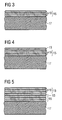
- Figure 3 schematically shows a first stage in the process of producing a rotor blade according to Figure 1.
- Figure 4 shows a second stage in the process of producing a rotor blade according to Figure 1.
- Figure 5 shows a third stage in the process of producing a rotor blade according to Figure 1.
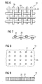
- Figure 6 shows a first example of a wrinkle-preventing layer used in the process of producing a rotor blade as shown in Figure 1 in a top view.
- Figure 7 shows the wrinkle-preventing layer of Figure 6 in a sectional view.
- Figure 8 shows a second example for a wrinkle-preventing layer used in the process of producing a rotor blade according to Figure 1 in a top view.
- Figure 9 shows the wrinkle-preventing layer of Figure 8 in a sectional view.
- Figure 1 is a schematic view of the cross-section of a laminated wind turbine rotor blade 1.
- the rotor blade 1 is made of an upper shell 3 and a lower shell 5 each comprising a thickened section 9 and non thickened sections 11.
- the upper and lower shells 3, 5 comprise a number of fibre reinforcement layers which are not individually shown in the figure. In the thickened section 9 the number of reinforcement layers is increased with respect to the non-thickened sections 11.
- the thickened section 9 of the upper shell 3 is shown in more detail in Figure 2.
- wrinkle-preventing layers 13 having a greater stiffness than the fibre reinforcement layers are present between stacks of fibre reinforcement layers 15.
- the fibre reinforcement layers 15, as well as the wrinkle-preventing layers 13, are embedded in a resin matrix which has been formed by resin infusion and subsequent curing of the resin.
- the wrinkle-preventing layers 13 prevent the fibre reinforcement layers from the formation of wrinkles as the higher stiffness does not allow the fibre reinforcement layers sandwiched between the mould and a wrinkle preventing layer 13 or between two wrinkle preventing layers 13 to fold substantially in the direction perpendicular to the extension of the fibres in the fibre reinforcement layers.
- the upper and lower shells 3, 5 of the rotor blade 1 are produced by placing dry fibre reinforcement layers on top of each other in a mould, wetting the fibre reinforcement layers by means of a resin infusion and subsequently curing the resin.
- the method which will be described with respect to Figures 3 to 5 can also be used for producing other fibre reinforced laminated structures, e.g. in boat building.
- FIG. 3 A first stage of the method for manufacturing the rotor blade 1 shown in Figure 1 is shown in Figure 3.
- the figure schematically shows a cut-out sectional view of the mould 17 and a number of fibre reinforcement layers 19, e.g. glass fibre layers, carbon fibre layers or aramid fibre layers, which are placed dry in the mould 17 on top of each other so as to form a stack 15 of the fibre reinforcement layers 19.
- fibre reinforcement layers 19 e.g. glass fibre layers, carbon fibre layers or aramid fibre layers
- layering stacks 15 of fibre reinforcement layers 19 and wrinkle-preventing layers 13 can be continued until the desired thickness of the layering is reached.
- the number of fibre reinforcement layers 19 in a stack 15 can be as high as possible without negatively influencing the wrinkle-preventing effect of the wrinkle-preventing layers 13.
- one or more additional wrinkle-preventing layers 13 may be present under the lowermost stack 15 of fibre reinforcement layers 19.
- a wrinkle-preventing layer 13 would be the first layer placed in the mould 17.
- the outermost layer of the overall stack consisting of stacks 15 of fibre reinforcement layers 19 alternating with wrinkle-preventing layers 13 may also be at least one wrinkle-preventing layer 13.
- the mould 17 is closed and a vacuum is applied to the mould. Then, a thermoplastic or thermosetting material such as the already mentioned resin, e.g. a polyester resin or an epoxy resin, is infused into the evacuated mould. The resin wets the fibre reinforcement layers and the wrinkle-preventing layers 13. After a while all fibre reinforcement layers 19, and also all wrinkle-preventing layers 13, are sufficiently wetted. Then, the resin is cured. After curing the resin, the mould 17 is dismantled.
- a thermoplastic or thermosetting material such as the already mentioned resin, e.g. a polyester resin or an epoxy resin
- the wrinkle-preventing layers 13 prevent the fibre reinforcement layers 19 from forming wrinkles, i.e. from folding up in a direction substantially perpendicular to the extension of the fibres in the fibre reinforcement layers 19 since they have higher stiffness than the fibre reinforcement layers 19 so that they do not fold themselves. As a consequence, there is no or only minimal space available for the formation of wrinkles between the mould 17 and a wrinkle-preventing layer 13 or between two wrinkle preventing layers 13.
- Figures 6 and 7 show a wrinkle-preventing layer 13 which is implemented as a mesh-like woven mat of a pre-cured laminate material. While Figure 6 shows a top view onto the mat, Figure 7 shows a sectional view through the mat.
- the laminate material of the mat may be, but does not need to be, the same material as the material of the fibre reinforcement layers 19.
- the woven mat is made from a glass fibre epoxy laminate, such as, for example, the Hexcel Polyspeed G-EV 984GI laminate type.
- the mesh-like structure of the wrinkle-preventing layer 13 allows for a flow of resin through the layer.
- threads 21, 22 of the woven structure provide space for a resin flow through the wrinkle-preventing layer 13 above and below the threads 21, 22.
- resin can flow through openings 23 between neighbouring threads from one side of the woven mat to the other.
- the corrugation of the mat due to its woven structure is exaggerated in Figure 7 and that the corrugation is small enough so that the mat can be considered as being flat in the scale of the wrinkles the formation of which is to be prevented. Moreover, the lateral scale of the mat's corrugation is much less than the scale of the wrinkles the formation of which shall be prevented. As a consequence, the mat does not form a source of wrinkle formation itself.
- Figures 8 and 9 show a wrinkle-preventing layer 13 which is implemented as a metal plate 25. While Figure 8 shows a top view onto the metal plate 25, Figure 9 shows a sectional view through the metal plate 25. Although the embodiment shown in Figures 8 and 9 is realised by a metal plate it could as well be realised by a plate of a different non-laminate material, for example wood, or by a plate of a pre-cured laminate material.
- a flow of resin through the metal plate 25 can be made possible by optional perforation holes 27 through which resin may easily flow from one side of the metal plate 25 to the other.
- the perforation holes 27 may, for example, be punched or stamped into the plate 25.
- the wrinkle-preventing layer 13 it becomes possible to provide a desired stiffness ratio of the wrinkle-preventing layers 13 to the fibre reinforcement layers 19 after curing the resin by using selected materials.
- the invention provides a method in which one or more layers of wrinkle-preventing material are placed inside a laminate.
- the method has the advantage that is prevents the occurrence of wrinkles in fibre reinforcement laminates.
- the method may further have the advantage that any wrinkles occurring despite the efforts with the wrinkle-preventing layers will be confined to the space between two layers of wrinkle-preventing material, or to the space between the surface of the laminate and a layer of the wrinkle-preventing material.
Landscapes
- Engineering & Computer Science (AREA)
- Chemical & Material Sciences (AREA)
- Composite Materials (AREA)
- Mechanical Engineering (AREA)
- Textile Engineering (AREA)
- Quality & Reliability (AREA)
- Moulding By Coating Moulds (AREA)
- Wind Motors (AREA)
- Casting Or Compression Moulding Of Plastics Or The Like (AREA)
Abstract
a) building up a part (15) of the laminate (13,15) to a determined thickness,
b) placing a layer (13) of material on top of the partially completed laminate (15), said layer (13) of material having a greater stiffness than the stiffness of a layer of similar thickness of the uncured laminate, and
c) building up a new part of the laminate (15) to a determined thickness.
In case the thickness of the laminate built up pursuant to the steps a) -c) is not as large as a desired thickness of the completed laminate, steps b) and c) are repeated until the thickness of the laminate built up is equal to the desired thickness of the completed laminate.
Description
- The present invention relates to a method for producing fibre reinforced laminate and to the use of a wrinkle-preventing material. In addition, the present invention relates to a wind turbine blade and a wind turbine.
- The structural characteristics of a fibre reinforced laminate are usually governed by the amount, type and orientation of the reinforcement fibres. Typically, the stiffness and strength of fibres can only be taken into account to the extent that loading occurs in the longitudinal fibre direction. Therefore, a traditionally designed laminate assumes that the fibres of the finished laminate will be oriented in the same direction as the direction of the fibres when placed in the mould. However, in some cases wrinkles in the fibre layers may occur as a result of the manufacturing process. In such cases the wrinkled fibres no longer have the desired orientation, and severe overload of the laminate may be the result.
- Wrinkles in fibre reinforced laminates are typically prevented by a combination of arrangements. The laminate thickness is kept below certain limits in order to minimise exothermal heat generation. Moulds and other surfaces on which the laminate is built up are maintained at a high quality. Curing is carried out at carefully controlled temperature gradients so as to minimise differences in the thermal expansion.
- If wrinkles do occur in fibre reinforced laminates despite preventive action repair or rejection of the laminate will usually be required, as the loss of stiffness and/or strength in wrinkles will often exceed any realistic safety margins.
- It is therefore an objective of the present invention to provide a method for manufacturing the fibre reinforced laminate which overcomes the mentioned difficulties. It is a further objective of the present invention to provide a use for a wrinkle-preventing material. A still further objective of the present invention is to provide an improved wind turbine blade and an improved wind turbine.
- The first objective is solved by a method for manufacturing a fibre reinforced laminate according to claim 1. The second objective is solved by using a wrinkle-preventing material as claimed in claim 10 and the third objective is solved by a wind turbine blade as claimed in
claim 17 and a wind turbine as claimed in claim 20. - In the inventive method for manufacturing a fibre reinforced laminate a part of the laminate is built up to a determined thickness. A layer of wrinkle-preventing material is placed on top of the partially completed laminate where the layer of wrinkle-preventing material has a greater stiffness than the stiffness of a layer of similar thickness of the uncured laminate. Then, a further part of the laminate is built up to a determined thickness. In case the thickness of the laminate built up by the mentioned process is not as large as a desired thickness of the completed laminate placing a layer of wrinkle-preventing material and a further part of the laminate is repeated until the thickness of the laminate built up is equal to the desired thickness of the completed laminate.
- By placing one or more layers of wrinkle-preventing material inside the partially completed laminate, the occurrence of wrinkles can be prevented in fibre reinforced laminates. Depending on the number of wrinkle-preventing layers, the method may have the further advantage that any wrinkles occurring despite the efforts of the wrinkle-preventing layers will be confined to the space between two layers of wrinkle-preventing material, or to the space between the surface of the laminate and a layer of wrinkle-preventing material. By thus confining the wrinkles to a limited thickness of the laminate, the reduction of strength and/or stiffness can be shown to be within the allowance of relevant safety factors.
- The inventive method is based on the following observations:
- Wrinkles may occur for a number of reasons. The thermal expansion of a laminate during curing may exceed the thermal expansion of the mould in which case the laminate may come under compressive pressure before the matrix material, which is typically a thermoplastic or a thermosetting material, is cured sufficiently to maintain the fibres in the desired orientation. Uneven structures underneath the laminate or undulations in the surface on which the laminate is built up may also induce wrinkles.
- While, as mentioned above, in the state of the art the formation of wrinkles has been prevented by keeping the laminate thickness below certain limits, maintaining the moulds and other surfaces on which the laminate is built up at high quality and carrying out curing at controlled temperature gradients the inventive method offers a new way of preventing wrinkle formation or at least for keeping the detrimental effects of wrinkles in a laminate within acceptable limits. The inventive method can therefore provide a relief of the limits used in the state of the art, i.e. the limits for the thickness of the laminate, the allowed evenness of the mould or any other surface on which the laminate is built up and the temperature gradient used during curing. On the other hand, the limit can be kept as stringent as in the state of the art in order to provide higher quality laminates, i.e. laminates with a reduced number of wrinkles, as compared to state of the art laminates.
- In the inventive method a layer of wrinkle-preventing material may be placed as the lowermost layer of the laminate and/or as the uppermost layer of the laminate. This would enhance the strength and/or stiffness of the part of the laminate which will become a surface after curing and dismantling the mould.
- A pre-cured layer of the same material as the material of the fibre layers may be used as the layer of wrinkle-preventing material. Pre-curing leads to a higher stiffness and/or strength of the material compared to its uncured state. Using the same material would have the advantage that only one kind of fibre reinforcement material is present in the laminate structure. Such a pre-cured material can be a pre-cured solid, perforated or mesh-like laminate. Perforated or mesh-like laminates would offer the further advantage that the flow of the thermoplastic or thermosetting material in the curing process would be less hindered than with a solid material.
- In an alternative implementation of the inventive method a pre-cured layer of a laminate material which is different to the laminate material of the fibre layers may be used. In this case the material of the pre-cured laminate layer is chosen such as to provide a desired stiffness ratio relative to the stiffness to the finished fibre reinforced laminate as the layer of wrinkle-preventing material. This embodiment offers the possibility of influencing the mechanical properties of the finished fibre reinforced laminate by suitably selecting the laminate material of the pre-cured layer. Also in this implementation, the pre-cured layer may be a pre-cured solid, perforated or mesh-like laminate.
- In a still further implementation of the inventive method a non-laminate layer, for example of wooden or metallic material, may be used as the layer of wrinkle-preventing material. For the non-laminate layer a solid, mesh-like or perforated layer may be used as the non-laminate wrinkle-preventing material.
- According to the invention a use for a wrinkle-preventing material is also provided in a method for manufacturing a fibre reinforcement laminate. As has been described with respect to the inventive method, the wrinkle-preventing material may be the same but pre-cured material as the fibre layers of the fibre reinforced laminate. Alternatively, the wrinkle-preventing material may be a material which is different to the material of the fibre layers. The material is then chosen such as to provide a desired stiffness ratio relative to the stiffness of the finished fibre reinforcement laminate. As a further alternative, the wrinkle-preventing material may be a non-laminate material, for example a wooden or metallic material. Irrespective of the chosen material the wrinkle-preventing material may be provided in the form of a solid, a mesh-like or a perforated material. The advantages of the different types of material for the wrinkle-preventing material have already been discussed with respect to the inventive method.
- An inventive wind turbine blade comprises a fibre reinforced laminate with at least one embedded anti-wrinkle layer. In particular, the fibre reinforced laminate may be comprised in an aerodynamic shell of the blade. The fibre reinforced laminate can be manufactured according to the inventive method. The embedded anti-wrinkle layer would then correspond to the layer of wrinkle-preventing material of the inventive method.
- The inventive wind turbine blade could have an improved laminate structure compared to state of the art wind turbine blades as the formation of wrinkles can be prevented or at least reduced by the embedded anti-wrinkle layer. Alternatively, the mechanical properties could be kept the same as in state of the art wind turbine blades. In this case, a wind turbine blade comprising a laminate structure with an anti-wrinkle layer could be manufactured with less effort and thus less costs since the anti-wrinkle layer would allow for releasing the restrictions on the quality of the mould or any surface on which the laminate structure is built up, the restrictions on the laminate thickness and/or the restrictions temperature gradient used when curing the laminate.
- An inventive wind turbine comprises an inventive wind turbine blade with all of the advantages mentioned above.
- Further features, properties and advantages of the present invention will become clear from the following description of an embodiment of the invention in conjunction with the accompanying drawings.
- Figure 1 schematically shows a section through a laminated wind turbine rotor blade.
- Figure 2 shows a detail of Figure 1.
- Figure 3 schematically shows a first stage in the process of producing a rotor blade according to Figure 1.
- Figure 4 shows a second stage in the process of producing a rotor blade according to Figure 1.
- Figure 5 shows a third stage in the process of producing a rotor blade according to Figure 1.
- Figure 6 shows a first example of a wrinkle-preventing layer used in the process of producing a rotor blade as shown in Figure 1 in a top view.
- Figure 7 shows the wrinkle-preventing layer of Figure 6 in a sectional view.
- Figure 8 shows a second example for a wrinkle-preventing layer used in the process of producing a rotor blade according to Figure 1 in a top view.
- Figure 9 shows the wrinkle-preventing layer of Figure 8 in a sectional view.
- Figure 1 is a schematic view of the cross-section of a laminated wind turbine rotor blade 1. The rotor blade 1 is made of an upper shell 3 and a lower shell 5 each comprising a thickened
section 9 and non thickenedsections 11. The upper and lower shells 3, 5 comprise a number of fibre reinforcement layers which are not individually shown in the figure. In the thickenedsection 9 the number of reinforcement layers is increased with respect to thenon-thickened sections 11. - The thickened
section 9 of the upper shell 3 is shown in more detail in Figure 2. In the thickenedsection 9, wrinkle-preventinglayers 13 having a greater stiffness than the fibre reinforcement layers are present between stacks of fibre reinforcement layers 15. The fibre reinforcement layers 15, as well as the wrinkle-preventinglayers 13, are embedded in a resin matrix which has been formed by resin infusion and subsequent curing of the resin. During the infusion and curing process the wrinkle-preventinglayers 13 prevent the fibre reinforcement layers from the formation of wrinkles as the higher stiffness does not allow the fibre reinforcement layers sandwiched between the mould and awrinkle preventing layer 13 or between twowrinkle preventing layers 13 to fold substantially in the direction perpendicular to the extension of the fibres in the fibre reinforcement layers. - The method of forming the wind turbine rotor blade 1 shown in Figures 1 and 2 will now be described with respect to Figures 3 to 5.
- In general, the upper and lower shells 3, 5 of the rotor blade 1 are produced by placing dry fibre reinforcement layers on top of each other in a mould, wetting the fibre reinforcement layers by means of a resin infusion and subsequently curing the resin. Please note that although described with respect to producing a wind turbine rotor blade 1, the method which will be described with respect to Figures 3 to 5 can also be used for producing other fibre reinforced laminated structures, e.g. in boat building.
- A first stage of the method for manufacturing the rotor blade 1 shown in Figure 1 is shown in Figure 3. The figure schematically shows a cut-out sectional view of the
mould 17 and a number of fibre reinforcement layers 19, e.g. glass fibre layers, carbon fibre layers or aramid fibre layers, which are placed dry in themould 17 on top of each other so as to form astack 15 of the fibre reinforcement layers 19. - After a
stack 15 of fibre reinforcement layers has been placed in the mould 17 a wrinkle-preventinglayer 13 is placed on top of the stack 15 (see Figure 4). - After the wrinkle-preventing
layer 13 has been placed on top of thefirst stack 15 of fibre reinforcement layers 19, anotherstack 15 comprising a number of fibre reinforcement layers 19 is placed on top of the wrinkle-preventinglayer 13, as shown in Figure 5. - Alternately layering stacks 15 of fibre reinforcement layers 19 and wrinkle-preventing
layers 13 can be continued until the desired thickness of the layering is reached. The number of fibre reinforcement layers 19 in astack 15 can be as high as possible without negatively influencing the wrinkle-preventing effect of the wrinkle-preventinglayers 13. - Although not shown in Figure 3 to 5, one or more additional wrinkle-preventing
layers 13 may be present under thelowermost stack 15 of fibre reinforcement layers 19. In this case, a wrinkle-preventinglayer 13 would be the first layer placed in themould 17. The outermost layer of the overall stack consisting ofstacks 15 of fibre reinforcement layers 19 alternating with wrinkle-preventinglayers 13 may also be at least one wrinkle-preventinglayer 13. - After the layering of the dry fibre reinforcement layers 19 and the dry wrinkle-preventing
layers 13, themould 17 is closed and a vacuum is applied to the mould. Then, a thermoplastic or thermosetting material such as the already mentioned resin, e.g. a polyester resin or an epoxy resin, is infused into the evacuated mould. The resin wets the fibre reinforcement layers and the wrinkle-preventinglayers 13. After a while all fibre reinforcement layers 19, and also all wrinkle-preventinglayers 13, are sufficiently wetted. Then, the resin is cured. After curing the resin, themould 17 is dismantled. - During the curing process the wrinkle-preventing
layers 13 prevent the fibre reinforcement layers 19 from forming wrinkles, i.e. from folding up in a direction substantially perpendicular to the extension of the fibres in the fibre reinforcement layers 19 since they have higher stiffness than the fibre reinforcement layers 19 so that they do not fold themselves. As a consequence, there is no or only minimal space available for the formation of wrinkles between themould 17 and a wrinkle-preventinglayer 13 or between two wrinkle preventing layers 13. Moreover, even if wrinkles would occur in astack 15 of fibre reinforcement layers sandwiched between themould 17 and a wrinkle-preventinglayer 13 or between twowrinkle preventing layers 13 such wrinkles would be confined to thisparticular stack 15 by the wrinkle-preventing layer(s) 13 since the wrinkles cannot propagate through the stiff wrinkle-preventing layer(s) 13. - Examples of wrinkle-preventing
layers 13 that may be used in the described method are shown in Figures 6 to 9. - Figures 6 and 7 show a wrinkle-preventing
layer 13 which is implemented as a mesh-like woven mat of a pre-cured laminate material. While Figure 6 shows a top view onto the mat, Figure 7 shows a sectional view through the mat. - The laminate material of the mat may be, but does not need to be, the same material as the material of the fibre reinforcement layers 19. In the present embodiment of the invention the woven mat is made from a glass fibre epoxy laminate, such as, for example, the Hexcel Polyspeed G-EV 984GI laminate type.
- Due to the fact that the mat is pre-cured its stiffness is higher that the stiffness of the not yet cured fibre reinforcement layers 19. The mesh-like structure of the wrinkle-preventing
layer 13 allows for a flow of resin through the layer. As can be seen from the figures,threads layer 13 above and below thethreads openings 23 between neighbouring threads from one side of the woven mat to the other. - Please note that the corrugation of the mat due to its woven structure is exaggerated in Figure 7 and that the corrugation is small enough so that the mat can be considered as being flat in the scale of the wrinkles the formation of which is to be prevented. Moreover, the lateral scale of the mat's corrugation is much less than the scale of the wrinkles the formation of which shall be prevented. As a consequence, the mat does not form a source of wrinkle formation itself.
- Figures 8 and 9 show a wrinkle-preventing
layer 13 which is implemented as ametal plate 25. While Figure 8 shows a top view onto themetal plate 25, Figure 9 shows a sectional view through themetal plate 25. Although the embodiment shown in Figures 8 and 9 is realised by a metal plate it could as well be realised by a plate of a different non-laminate material, for example wood, or by a plate of a pre-cured laminate material. - A flow of resin through the
metal plate 25 can be made possible by optional perforation holes 27 through which resin may easily flow from one side of themetal plate 25 to the other. The perforation holes 27 may, for example, be punched or stamped into theplate 25. - In both depicted implementations of the wrinkle-preventing
layer 13 it becomes possible to provide a desired stiffness ratio of the wrinkle-preventinglayers 13 to the fibre reinforcement layers 19 after curing the resin by using selected materials. - The invention provides a method in which one or more layers of wrinkle-preventing material are placed inside a laminate. The method has the advantage that is prevents the occurrence of wrinkles in fibre reinforcement laminates. Depending on the number of wrinkle-preventing layers, the method may further have the advantage that any wrinkles occurring despite the efforts with the wrinkle-preventing layers will be confined to the space between two layers of wrinkle-preventing material, or to the space between the surface of the laminate and a layer of the wrinkle-preventing material. By thus confining the wrinkle to a limited thickness of the laminate, the reduction of strength and/or stiffness can be shown to be within the allowance of relevant safety factors.
Claims (20)
- A method for manufacturing of a fiber reinforced laminate (13, 15), comprising the steps of:a) building up a part (15) of the laminate (13, 15) to a determined thickness,b) placing a layer (13) of wrinkle-preventing material on top of the partially completed laminate (15), said layer (13) of wrinkle-preventing material having a greater stiffness than the stiffness of a layer of similar thickness of the uncured laminate,c) building up a new part of the laminate (15) to a determined thickness, andd) in case the thickness of the laminate built up pursuant to the steps a)-c) is not as large as a desired thickness of the completed laminate, repeating steps b) and c) until the thickness of the laminate built up is equal to the desired thickness of the completed laminate.
- The method as claimed in claim 1, wherein a layer (13) of wrinkle-preventing material is placed as the lowermost layer of the laminate.
- The method as claimed in claim 1 or claim 2, wherein a layer (13) of wrinkle-preventing material is placed as the uppermost layer of the laminate.
- The method as claimed in any of the preceding claims, wherein a pre-cured layer of the same material as the material of the fibre layers is used as the layer (13) of wrinkle-preventing material.
- The method as claimed in any of the claims 1 to 3, wherein a pre-cured layer of a laminate material which is different to the material of the fibre layers and chosen such as to provide a desired stiffness ratio relative to the stiffness of the finished fiber reinforced laminate is used as the layer (13) of wrinkle-preventing material.
- The method as claimed in any of the claims 1 to 3, wherein a non-laminate layer is used as the layer (13) of wrinkle-preventing material.
- The method as claimed in claim 6, wherein a layer of wooden or metallic material is used as the layer (13) of wrinkle-preventing material.
- The method as claimed in any of the claims 4 to 7, wherein a solid layer is used as the layer (13) of wrinkle-preventing material.
- The method as claimed in any of the claims 4 to 7, wherein a mesh-like or perforated layer is used as the layer (13) of wrinkle-preventing material.
- Use of a wrinkle-preventing material in a method for manufacturing of a fibre reinforced laminate.
- The use as claimed in claim 10, wherein the wrinkle-preventing material is the same but pre-cured material as the material of the fibre layers of the fibre reinforced laminate.
- The use as claimed in claim 10, wherein the wrinkle-preventing material is a material different to the material of the fibre layers which is chosen such as to provide a desired stiffness ratio relative to the stiffness of the finished fiber reinforced laminate.
- The use as claimed in claim 10, wherein the wrinkle-preventing material is a non-laminate material.
- The use as claimed in claim 13, wherein the wrinkle-preventing material is a wooden or metallic material.
- The use as claimed in any of the claims 10 to 14, wherein the wrinkle-preventing material is a mesh-like or perforated material.
- The use as claimed in any of the claims 10 to 14, wherein the wrinkle-preventing material is a solid material.
- A wind turbine blade (1) comprising a fibre reinforced laminate (13, 15) with at least one embedded anti-wrinkle layer (13).
- The wind turbine blade (1) as claimed in claim 17 with an aerodynamic shell comprising the fibre reinforced laminate (13, 15).
- The wind turbine blade (1) according to claim 17 or claim 18, wherein the fibre reinforced laminate (13, 15) is manufactured according to the method of any of the claims 1 to 9.
- A wind turbine comprising a wind turbine blade (1) according to any of the claims 17 to 19.
Priority Applications (5)
| Application Number | Priority Date | Filing Date | Title |
|---|---|---|---|
| ES07013723T ES2392187T3 (en) | 2006-11-23 | 2007-07-12 | Method for manufacturing a fiber reinforced laminated material, use of this laminated material, wind turbine blade and wind turbine comprising this laminated material |
| EP20070013723 EP1925436B1 (en) | 2006-11-23 | 2007-07-12 | Method for manufacturing of a fibre reinforced laminate, use of this laminate, wind turbine blade and wind turbine comprising this laminate |
| DK07013723.7T DK1925436T3 (en) | 2006-11-23 | 2007-07-12 | Process for producing a fiber-reinforced laminate, use of the laminate, wind turbine blade and wind turbine comprising the laminate |
| US11/986,037 US8079818B2 (en) | 2006-11-23 | 2007-11-19 | Method for manufacturing of a fibre reinforced laminate, use of a wrinkle-preventing material, wind turbine blade and wind turbine |
| CA2611425A CA2611425C (en) | 2006-11-23 | 2007-11-21 | Method for manufacturing of a fibre reinforced laminate, use of a wrinkle-preventing material, wind turbine blade and wind turbine |
Applications Claiming Priority (2)
| Application Number | Priority Date | Filing Date | Title |
|---|---|---|---|
| EP06024335 | 2006-11-23 | ||
| EP20070013723 EP1925436B1 (en) | 2006-11-23 | 2007-07-12 | Method for manufacturing of a fibre reinforced laminate, use of this laminate, wind turbine blade and wind turbine comprising this laminate |
Publications (2)
| Publication Number | Publication Date |
|---|---|
| EP1925436A1 true EP1925436A1 (en) | 2008-05-28 |
| EP1925436B1 EP1925436B1 (en) | 2012-08-29 |
Family
ID=38952088
Family Applications (1)
| Application Number | Title | Priority Date | Filing Date |
|---|---|---|---|
| EP20070013723 Revoked EP1925436B1 (en) | 2006-11-23 | 2007-07-12 | Method for manufacturing of a fibre reinforced laminate, use of this laminate, wind turbine blade and wind turbine comprising this laminate |
Country Status (5)
| Country | Link |
|---|---|
| US (1) | US8079818B2 (en) |
| EP (1) | EP1925436B1 (en) |
| CA (1) | CA2611425C (en) |
| DK (1) | DK1925436T3 (en) |
| ES (1) | ES2392187T3 (en) |
Cited By (11)
| Publication number | Priority date | Publication date | Assignee | Title |
|---|---|---|---|---|
| WO2010050860A1 (en) * | 2008-10-29 | 2010-05-06 | Saab Ab | Hot drape forming by means of a stiffness controlled vacuum bag |
| CN101614182B (en) * | 2009-06-05 | 2011-05-18 | 内蒙古工大博远风电装备制造有限公司 | Wind power generation unit blade reinforced with needle fiber and fabrication process thereof |
| WO2011142699A1 (en) * | 2010-05-11 | 2011-11-17 | Saab Ab | A composite article comprising particles and a method of forming a composite article |
| US20140099477A1 (en) * | 2012-10-04 | 2014-04-10 | The Boeing Company | Composite structure having a stabilizing element |
| WO2014166493A1 (en) * | 2013-04-08 | 2014-10-16 | Vestas Wind Systems A/S | A fibre preform for laying on a curved surface of a mould |
| US9073270B2 (en) | 2009-01-21 | 2015-07-07 | Vestas Wind Systems A/S | Method of manufacturing a wind turbine blade by embedding a layer of pre-cured fibre reinforced resin |
| WO2016001040A1 (en) | 2014-06-30 | 2016-01-07 | Hexcel Holding Gmbh | Non-woven fabrics |
| EP2349686A4 (en) * | 2008-11-13 | 2016-09-28 | Saab Ab | METHOD FOR FORMING A COMPOSITE ARTICLE |
| EP2679372A4 (en) * | 2011-02-25 | 2017-08-30 | Toray Industries, Inc. | Method for producing frp |
| DE102017126276A1 (en) | 2017-11-09 | 2019-05-09 | Nordex Energy Gmbh | Method for producing a web-belt assembly for a wind turbine rotor blade and web-belt assembly |
| DE102018009379A1 (en) * | 2018-11-30 | 2020-06-04 | Airbus Operations Gmbh | New method for producing a flat component in some areas from a fiber composite material |
Families Citing this family (31)
| Publication number | Priority date | Publication date | Assignee | Title |
|---|---|---|---|---|
| GB0807306D0 (en) * | 2008-04-22 | 2008-05-28 | Univ Ghent | Adjuvants for use in vaccination |
| DK2358998T3 (en) | 2008-12-05 | 2017-10-30 | Vestas Wind Sys As | EFFICIENT WINDOWS, WINDOWS, AND ASSOCIATED SYSTEMS AND PROCEDURES FOR MANUFACTURING, INSTALLING AND USING |
| US20110052404A1 (en) * | 2009-08-25 | 2011-03-03 | Zuteck Michael D | Swept blades with enhanced twist response |
| US10137542B2 (en) | 2010-01-14 | 2018-11-27 | Senvion Gmbh | Wind turbine rotor blade components and machine for making same |
| BR112012017122B1 (en) | 2010-01-14 | 2021-09-28 | Senvion Gmbh | COMPOSITE BEAM FOR A WIND TURBINE SHOVEL |
| GB201007336D0 (en) * | 2010-04-30 | 2010-06-16 | Blade Dynamics Ltd | A modular structural composite beam |
| US9500179B2 (en) | 2010-05-24 | 2016-11-22 | Vestas Wind Systems A/S | Segmented wind turbine blades with truss connection regions, and associated systems and methods |
| US20120087801A1 (en) * | 2010-10-12 | 2012-04-12 | General Electric Company | Composite components and processes therefor |
| GB201215004D0 (en) | 2012-08-23 | 2012-10-10 | Blade Dynamics Ltd | Wind turbine tower |
| GB201217212D0 (en) | 2012-09-26 | 2012-11-07 | Blade Dynamics Ltd | Windturbine blade |
| GB201217210D0 (en) | 2012-09-26 | 2012-11-07 | Blade Dynamics Ltd | A metod of forming a structural connection between a spar cap fairing for a wind turbine blade |
| US9964096B2 (en) * | 2013-01-10 | 2018-05-08 | Wei7 Llc | Triaxial fiber-reinforced composite laminate |
| US9470205B2 (en) | 2013-03-13 | 2016-10-18 | Vestas Wind Systems A/S | Wind turbine blades with layered, multi-component spars, and associated systems and methods |
| US10337490B2 (en) | 2015-06-29 | 2019-07-02 | General Electric Company | Structural component for a modular rotor blade |
| US9897065B2 (en) | 2015-06-29 | 2018-02-20 | General Electric Company | Modular wind turbine rotor blades and methods of assembling same |
| US10072632B2 (en) | 2015-06-30 | 2018-09-11 | General Electric Company | Spar cap for a wind turbine rotor blade formed from pre-cured laminate plates of varying thicknesses |
| US10077758B2 (en) | 2015-06-30 | 2018-09-18 | General Electric Company | Corrugated pre-cured laminate plates for use within wind turbine rotor blades |
| US9951750B2 (en) | 2015-07-30 | 2018-04-24 | General Electric Company | Rotor blade with interior shelf for a flat plate spar cap |
| US10107257B2 (en) | 2015-09-23 | 2018-10-23 | General Electric Company | Wind turbine rotor blade components formed from pultruded hybrid-resin fiber-reinforced composites |
| US10113532B2 (en) | 2015-10-23 | 2018-10-30 | General Electric Company | Pre-cured composites for rotor blade components |
| US10422316B2 (en) | 2016-08-30 | 2019-09-24 | General Electric Company | Pre-cured rotor blade components having areas of variable stiffness |
| US10738759B2 (en) | 2017-02-09 | 2020-08-11 | General Electric Company | Methods for manufacturing spar caps for wind turbine rotor blades |
| US10527023B2 (en) | 2017-02-09 | 2020-01-07 | General Electric Company | Methods for manufacturing spar caps for wind turbine rotor blades |
| US10677216B2 (en) | 2017-10-24 | 2020-06-09 | General Electric Company | Wind turbine rotor blade components formed using pultruded rods |
| US11738530B2 (en) | 2018-03-22 | 2023-08-29 | General Electric Company | Methods for manufacturing wind turbine rotor blade components |
| DK180296B1 (en) * | 2019-02-19 | 2020-10-14 | Mm Composite As | Method for manufacturing of a fibre-reinforced laminate |
| DK180292B1 (en) * | 2019-02-19 | 2020-10-12 | Mm Composite As | Method and apparatus for treatment of a fibre mat |
| DK180294B1 (en) * | 2019-02-19 | 2020-10-13 | Mm Composite As | Method and apparatus for treatment of a fibre mat |
| AT521599B1 (en) * | 2019-03-12 | 2020-03-15 | Schmidt Michael | ROTOR BLADE FOR A ROTOR FOR A WIND TURBINE |
| CN114072263B (en) | 2019-07-16 | 2024-06-21 | Lm风力发电公司 | System and method for manufacturing panels for use in wind turbine rotor blade components |
| US12365120B2 (en) | 2019-07-16 | 2025-07-22 | Ge Infrastructure Technology Llc | System and method for manufacturing panels for use in wind turbine rotor blade components |
Citations (4)
| Publication number | Priority date | Publication date | Assignee | Title |
|---|---|---|---|---|
| US5064705A (en) | 1989-08-28 | 1991-11-12 | United Technologies Corporation | Stabilizing laminate inserts for resin transfer molding |
| WO1995020479A1 (en) * | 1994-01-26 | 1995-08-03 | Amp-Akzo Linlam Vof | Method of making a ud crossply pwb laminate having one or more inner layers of metal |
| WO2004071761A1 (en) * | 2003-02-17 | 2004-08-26 | Stichting Fmlc | Laminate of metal plates and intersecting fibre layers |
| US20050048260A1 (en) | 2003-08-27 | 2005-03-03 | The Boeing Company | Method and apparatus for fabricating a laminated fiber metal composite |
Family Cites Families (2)
| Publication number | Priority date | Publication date | Assignee | Title |
|---|---|---|---|---|
| US5061542A (en) * | 1989-08-28 | 1991-10-29 | United Technologies Corporation | Stabilizing foam inserts for resin transfer molding |
| GB9118186D0 (en) * | 1991-08-23 | 1991-10-09 | British Aerospace | Fusion bonded thermoplastic leading edge for aircraft aerodynamic |
-
2007
- 2007-07-12 DK DK07013723.7T patent/DK1925436T3/en active
- 2007-07-12 ES ES07013723T patent/ES2392187T3/en active Active
- 2007-07-12 EP EP20070013723 patent/EP1925436B1/en not_active Revoked
- 2007-11-19 US US11/986,037 patent/US8079818B2/en active Active
- 2007-11-21 CA CA2611425A patent/CA2611425C/en active Active
Patent Citations (4)
| Publication number | Priority date | Publication date | Assignee | Title |
|---|---|---|---|---|
| US5064705A (en) | 1989-08-28 | 1991-11-12 | United Technologies Corporation | Stabilizing laminate inserts for resin transfer molding |
| WO1995020479A1 (en) * | 1994-01-26 | 1995-08-03 | Amp-Akzo Linlam Vof | Method of making a ud crossply pwb laminate having one or more inner layers of metal |
| WO2004071761A1 (en) * | 2003-02-17 | 2004-08-26 | Stichting Fmlc | Laminate of metal plates and intersecting fibre layers |
| US20050048260A1 (en) | 2003-08-27 | 2005-03-03 | The Boeing Company | Method and apparatus for fabricating a laminated fiber metal composite |
Cited By (21)
| Publication number | Priority date | Publication date | Assignee | Title |
|---|---|---|---|---|
| US8840828B2 (en) | 2008-10-29 | 2014-09-23 | Saab Ab | Hot drape forming by means of a stiffness controlled vacuum bag |
| WO2010050860A1 (en) * | 2008-10-29 | 2010-05-06 | Saab Ab | Hot drape forming by means of a stiffness controlled vacuum bag |
| EP2349686A4 (en) * | 2008-11-13 | 2016-09-28 | Saab Ab | METHOD FOR FORMING A COMPOSITE ARTICLE |
| US10590909B2 (en) | 2009-01-21 | 2020-03-17 | Vestas Wind Systems A/S | Method of manufacturing a wind turbine blade by embedding a layer of pre-cured fibre reinforced resin |
| EP2379312B1 (en) * | 2009-01-21 | 2019-04-03 | Vestas Wind Systems A/S | Method of manufacturing a wind turbine blade and pre-form for use in a wind turbine blade |
| US9073270B2 (en) | 2009-01-21 | 2015-07-07 | Vestas Wind Systems A/S | Method of manufacturing a wind turbine blade by embedding a layer of pre-cured fibre reinforced resin |
| CN101614182B (en) * | 2009-06-05 | 2011-05-18 | 内蒙古工大博远风电装备制造有限公司 | Wind power generation unit blade reinforced with needle fiber and fabrication process thereof |
| WO2011142699A1 (en) * | 2010-05-11 | 2011-11-17 | Saab Ab | A composite article comprising particles and a method of forming a composite article |
| EP2679372A4 (en) * | 2011-02-25 | 2017-08-30 | Toray Industries, Inc. | Method for producing frp |
| US9517594B2 (en) * | 2012-10-04 | 2016-12-13 | The Boeing Company | Composite structure having a stabilizing element |
| CN104703781A (en) * | 2012-10-04 | 2015-06-10 | 波音公司 | Composite structure with stabilizing elements |
| CN104703781B (en) * | 2012-10-04 | 2019-02-15 | 波音公司 | Composite structures with stabilizing elements |
| KR20200008035A (en) * | 2012-10-04 | 2020-01-22 | 더 보잉 컴파니 | Composite structure having a stabilizing element |
| US20140099477A1 (en) * | 2012-10-04 | 2014-04-10 | The Boeing Company | Composite structure having a stabilizing element |
| EP2903801B1 (en) * | 2012-10-04 | 2020-12-30 | The Boeing Company | Composite structure having a stabilizing element |
| CN105283283B (en) * | 2013-04-08 | 2017-05-10 | 维斯塔斯风力系统有限公司 | A fibre preform for laying on a curved surface of a mould |
| US10179425B2 (en) | 2013-04-08 | 2019-01-15 | Vestas Wind Systems A/S | Fibre preform for laying on a curved surface of a mould |
| WO2014166493A1 (en) * | 2013-04-08 | 2014-10-16 | Vestas Wind Systems A/S | A fibre preform for laying on a curved surface of a mould |
| WO2016001040A1 (en) | 2014-06-30 | 2016-01-07 | Hexcel Holding Gmbh | Non-woven fabrics |
| DE102017126276A1 (en) | 2017-11-09 | 2019-05-09 | Nordex Energy Gmbh | Method for producing a web-belt assembly for a wind turbine rotor blade and web-belt assembly |
| DE102018009379A1 (en) * | 2018-11-30 | 2020-06-04 | Airbus Operations Gmbh | New method for producing a flat component in some areas from a fiber composite material |
Also Published As
| Publication number | Publication date |
|---|---|
| ES2392187T3 (en) | 2012-12-05 |
| DK1925436T3 (en) | 2012-09-24 |
| US20090175731A1 (en) | 2009-07-09 |
| CA2611425A1 (en) | 2008-05-23 |
| CA2611425C (en) | 2014-07-08 |
| EP1925436B1 (en) | 2012-08-29 |
| US8079818B2 (en) | 2011-12-20 |
Similar Documents
| Publication | Publication Date | Title |
|---|---|---|
| US8079818B2 (en) | Method for manufacturing of a fibre reinforced laminate, use of a wrinkle-preventing material, wind turbine blade and wind turbine | |
| US8157939B2 (en) | Method for manufacturing of a fibre reinforced laminate and of a laterally extended material which has in a first lateral direction a greater stiffness than in a second lateral direction | |
| EP1990178A1 (en) | Method for producing fibre reinforced laminated structures | |
| CN102602063B (en) | Fiber-reinforced layer casting die and manufacture method and stiffener thereof and wind turbine blade | |
| JP4558091B1 (en) | Fiber-reinforced molded body and method for producing the same | |
| EP2661357B1 (en) | Laminate pre-form for a wind turbine blade and method of its manufacture | |
| CN1915649B (en) | Method for making a continuous laminate, in particular suitable as a spar cap or another part of a wind energy turbine rotor blade | |
| RU2469861C2 (en) | Method of manufacturing core composite provided from both sides with covering layers | |
| DE102014100035B4 (en) | COMPOSITE CONSTRUCTION PLATE AND METHOD FOR CREATING SUCH A PLATE | |
| US8592024B2 (en) | Repair of perforated acoustic skins by reverse pin transfer molding | |
| US20100080980A1 (en) | Molding process for core-containing composites and composites formed thereby | |
| US20100196654A1 (en) | Process for producing composite laminate structures and composite laminate structures formed thereby | |
| WO2018051445A1 (en) | Method for molding composite material, and composite material | |
| JP4370797B2 (en) | FRP thin plate manufacturing method | |
| JP2007099966A (en) | Prepreg | |
| GB2640453A (en) | Basalt fabric material | |
| JP2012131230A (en) | Laminate manufacturing method | |
| JP2018039130A (en) | Composite material molding method and composite material molding apparatus | |
| CN109760334B (en) | Anti-wrinkle prefabricated part and manufacturing method thereof |
Legal Events
| Date | Code | Title | Description |
|---|---|---|---|
| PUAI | Public reference made under article 153(3) epc to a published international application that has entered the european phase |
Free format text: ORIGINAL CODE: 0009012 |
|
| AK | Designated contracting states |
Kind code of ref document: A1 Designated state(s): AT BE BG CH CY CZ DE DK EE ES FI FR GB GR HU IE IS IT LI LT LU LV MC MT NL PL PT RO SE SI SK TR |
|
| AX | Request for extension of the european patent |
Extension state: AL BA HR MK RS |
|
| 17P | Request for examination filed |
Effective date: 20080710 |
|
| AKX | Designation fees paid |
Designated state(s): DE DK ES GB |
|
| 17Q | First examination report despatched |
Effective date: 20090318 |
|
| REG | Reference to a national code |
Ref country code: DE Ref legal event code: R079 Ref document number: 602007025054 Country of ref document: DE Free format text: PREVIOUS MAIN CLASS: B29C0070540000 Ipc: B29C0070080000 |
|
| GRAP | Despatch of communication of intention to grant a patent |
Free format text: ORIGINAL CODE: EPIDOSNIGR1 |
|
| RIC1 | Information provided on ipc code assigned before grant |
Ipc: B29C 70/54 20060101ALI20120203BHEP Ipc: B29C 70/08 20060101AFI20120203BHEP |
|
| GRAS | Grant fee paid |
Free format text: ORIGINAL CODE: EPIDOSNIGR3 |
|
| GRAA | (expected) grant |
Free format text: ORIGINAL CODE: 0009210 |
|
| AK | Designated contracting states |
Kind code of ref document: B1 Designated state(s): DE DK ES GB |
|
| REG | Reference to a national code |
Ref country code: GB Ref legal event code: FG4D |
|
| REG | Reference to a national code |
Ref country code: DK Ref legal event code: T3 |
|
| REG | Reference to a national code |
Ref country code: DE Ref legal event code: R096 Ref document number: 602007025054 Country of ref document: DE Effective date: 20121018 |
|
| REG | Reference to a national code |
Ref country code: ES Ref legal event code: FG2A Ref document number: 2392187 Country of ref document: ES Kind code of ref document: T3 Effective date: 20121205 |
|
| RAP2 | Party data changed (patent owner data changed or rights of a patent transferred) |
Owner name: SIEMENS AKTIENGESELLSCHAFT |
|
| PLBI | Opposition filed |
Free format text: ORIGINAL CODE: 0009260 |
|
| PLBI | Opposition filed |
Free format text: ORIGINAL CODE: 0009260 |
|
| PLAX | Notice of opposition and request to file observation + time limit sent |
Free format text: ORIGINAL CODE: EPIDOSNOBS2 |
|
| 26 | Opposition filed |
Opponent name: LM WP PATENT HOLDING A/S Effective date: 20130528 |
|
| 26 | Opposition filed |
Opponent name: SSP TECHNOLOGY A/S Effective date: 20130529 Opponent name: VESTAS WIND SYSTEMS A/S Effective date: 20130529 Opponent name: HEXCEL CORPORATION Effective date: 20130529 |
|
| REG | Reference to a national code |
Ref country code: DE Ref legal event code: R026 Ref document number: 602007025054 Country of ref document: DE Effective date: 20130528 |
|
| PLAF | Information modified related to communication of a notice of opposition and request to file observations + time limit |
Free format text: ORIGINAL CODE: EPIDOSCOBS2 |
|
| PLBB | Reply of patent proprietor to notice(s) of opposition received |
Free format text: ORIGINAL CODE: EPIDOSNOBS3 |
|
| PLAB | Opposition data, opponent's data or that of the opponent's representative modified |
Free format text: ORIGINAL CODE: 0009299OPPO |
|
| R26 | Opposition filed (corrected) |
Opponent name: SSP TECHNOLOGY A/S Effective date: 20130529 |
|
| RDAF | Communication despatched that patent is revoked |
Free format text: ORIGINAL CODE: EPIDOSNREV1 |
|
| APBM | Appeal reference recorded |
Free format text: ORIGINAL CODE: EPIDOSNREFNO |
|
| APBP | Date of receipt of notice of appeal recorded |
Free format text: ORIGINAL CODE: EPIDOSNNOA2O |
|
| APAH | Appeal reference modified |
Free format text: ORIGINAL CODE: EPIDOSCREFNO |
|
| APBQ | Date of receipt of statement of grounds of appeal recorded |
Free format text: ORIGINAL CODE: EPIDOSNNOA3O |
|
| PLAB | Opposition data, opponent's data or that of the opponent's representative modified |
Free format text: ORIGINAL CODE: 0009299OPPO |
|
| R26 | Opposition filed (corrected) |
Opponent name: SSP TECHNOLOGY A/S Effective date: 20130529 |
|
| RAP2 | Party data changed (patent owner data changed or rights of a patent transferred) |
Owner name: SIEMENS AKTIENGESELLSCHAFT |
|
| PLAB | Opposition data, opponent's data or that of the opponent's representative modified |
Free format text: ORIGINAL CODE: 0009299OPPO |
|
| R26 | Opposition filed (corrected) |
Opponent name: SSP TECHNOLOGY A/S Effective date: 20130529 |
|
| PLAB | Opposition data, opponent's data or that of the opponent's representative modified |
Free format text: ORIGINAL CODE: 0009299OPPO |
|
| R26 | Opposition filed (corrected) |
Opponent name: LM WP PATENT HOLDING A/S Effective date: 20130528 |
|
| PLAB | Opposition data, opponent's data or that of the opponent's representative modified |
Free format text: ORIGINAL CODE: 0009299OPPO |
|
| R26 | Opposition filed (corrected) |
Opponent name: LM WP PATENT HOLDING A/S Effective date: 20130528 |
|
| RAP2 | Party data changed (patent owner data changed or rights of a patent transferred) |
Owner name: SIEMENS GAMESA RENEWABLE ENERGY A/S |
|
| REG | Reference to a national code |
Ref country code: DE Ref legal event code: R081 Ref document number: 602007025054 Country of ref document: DE Owner name: SIEMENS GAMESA RENEWABLE ENERGY A/S, DK Free format text: FORMER OWNER: SIEMENS AKTIENGESELLSCHAFT, 80333 MUENCHEN, DE |
|
| REG | Reference to a national code |
Ref country code: GB Ref legal event code: 732E Free format text: REGISTERED BETWEEN 20200102 AND 20200108 |
|
| PGFP | Annual fee paid to national office [announced via postgrant information from national office to epo] |
Ref country code: GB Payment date: 20200813 Year of fee payment: 14 Ref country code: DE Payment date: 20200921 Year of fee payment: 14 |
|
| PGFP | Annual fee paid to national office [announced via postgrant information from national office to epo] |
Ref country code: ES Payment date: 20201026 Year of fee payment: 14 |
|
| PLAB | Opposition data, opponent's data or that of the opponent's representative modified |
Free format text: ORIGINAL CODE: 0009299OPPO |
|
| R26 | Opposition filed (corrected) |
Opponent name: HEXCEL CORPORATION Effective date: 20130529 |
|
| REG | Reference to a national code |
Ref country code: DE Ref legal event code: R064 Ref document number: 602007025054 Country of ref document: DE Ref country code: DE Ref legal event code: R103 Ref document number: 602007025054 Country of ref document: DE |
|
| APBU | Appeal procedure closed |
Free format text: ORIGINAL CODE: EPIDOSNNOA9O |
|
| RDAG | Patent revoked |
Free format text: ORIGINAL CODE: 0009271 |
|
| STAA | Information on the status of an ep patent application or granted ep patent |
Free format text: STATUS: PATENT REVOKED |
|
| 27W | Patent revoked |
Effective date: 20210629 |
|
| GBPR | Gb: patent revoked under art. 102 of the ep convention designating the uk as contracting state |
Effective date: 20210629 |
|
| PGFP | Annual fee paid to national office [announced via postgrant information from national office to epo] |
Ref country code: DK Payment date: 20210723 Year of fee payment: 15 |