EP1925373A1 - Method of cooling steel sheet - Google Patents
Method of cooling steel sheet Download PDFInfo
- Publication number
- EP1925373A1 EP1925373A1 EP07791993A EP07791993A EP1925373A1 EP 1925373 A1 EP1925373 A1 EP 1925373A1 EP 07791993 A EP07791993 A EP 07791993A EP 07791993 A EP07791993 A EP 07791993A EP 1925373 A1 EP1925373 A1 EP 1925373A1
- Authority
- EP
- European Patent Office
- Prior art keywords
- steel plate
- region
- cooling
- water density
- part region
- Prior art date
- Legal status (The legal status is an assumption and is not a legal conclusion. Google has not performed a legal analysis and makes no representation as to the accuracy of the status listed.)
- Granted
Links
Images


Classifications
-
- B—PERFORMING OPERATIONS; TRANSPORTING
- B21—MECHANICAL METAL-WORKING WITHOUT ESSENTIALLY REMOVING MATERIAL; PUNCHING METAL
- B21B—ROLLING OF METAL
- B21B37/00—Control devices or methods specially adapted for metal-rolling mills or the work produced thereby
- B21B37/74—Temperature control, e.g. by cooling or heating the rolls or the product
- B21B37/76—Cooling control on the run-out table
-
- B—PERFORMING OPERATIONS; TRANSPORTING
- B21—MECHANICAL METAL-WORKING WITHOUT ESSENTIALLY REMOVING MATERIAL; PUNCHING METAL
- B21B—ROLLING OF METAL
- B21B45/00—Devices for surface or other treatment of work, specially combined with or arranged in, or specially adapted for use in connection with, metal-rolling mills
- B21B45/04—Devices for surface or other treatment of work, specially combined with or arranged in, or specially adapted for use in connection with, metal-rolling mills for de-scaling, e.g. by brushing
- B21B45/08—Devices for surface or other treatment of work, specially combined with or arranged in, or specially adapted for use in connection with, metal-rolling mills for de-scaling, e.g. by brushing hydraulically
-
- B—PERFORMING OPERATIONS; TRANSPORTING
- B21—MECHANICAL METAL-WORKING WITHOUT ESSENTIALLY REMOVING MATERIAL; PUNCHING METAL
- B21B—ROLLING OF METAL
- B21B45/00—Devices for surface or other treatment of work, specially combined with or arranged in, or specially adapted for use in connection with, metal-rolling mills
- B21B45/04—Devices for surface or other treatment of work, specially combined with or arranged in, or specially adapted for use in connection with, metal-rolling mills for de-scaling, e.g. by brushing
- B21B45/06—Devices for surface or other treatment of work, specially combined with or arranged in, or specially adapted for use in connection with, metal-rolling mills for de-scaling, e.g. by brushing of strip material
-
- C—CHEMISTRY; METALLURGY
- C21—METALLURGY OF IRON
- C21D—MODIFYING THE PHYSICAL STRUCTURE OF FERROUS METALS; GENERAL DEVICES FOR HEAT TREATMENT OF FERROUS OR NON-FERROUS METALS OR ALLOYS; MAKING METAL MALLEABLE, e.g. BY DECARBURISATION OR TEMPERING
- C21D1/00—General methods or devices for heat treatment, e.g. annealing, hardening, quenching or tempering
- C21D1/62—Quenching devices
- C21D1/667—Quenching devices for spray quenching
-
- B—PERFORMING OPERATIONS; TRANSPORTING
- B21—MECHANICAL METAL-WORKING WITHOUT ESSENTIALLY REMOVING MATERIAL; PUNCHING METAL
- B21B—ROLLING OF METAL
- B21B2273/00—Path parameters
- B21B2273/12—End of product
- B21B2273/14—Front end or leading end
-
- B—PERFORMING OPERATIONS; TRANSPORTING
- B21—MECHANICAL METAL-WORKING WITHOUT ESSENTIALLY REMOVING MATERIAL; PUNCHING METAL
- B21B—ROLLING OF METAL
- B21B2273/00—Path parameters
- B21B2273/12—End of product
- B21B2273/16—Tail or rear end
-
- B—PERFORMING OPERATIONS; TRANSPORTING
- B21—MECHANICAL METAL-WORKING WITHOUT ESSENTIALLY REMOVING MATERIAL; PUNCHING METAL
- B21B—ROLLING OF METAL
- B21B2273/00—Path parameters
- B21B2273/18—Presence of product
-
- B—PERFORMING OPERATIONS; TRANSPORTING
- B21—MECHANICAL METAL-WORKING WITHOUT ESSENTIALLY REMOVING MATERIAL; PUNCHING METAL
- B21B—ROLLING OF METAL
- B21B37/00—Control devices or methods specially adapted for metal-rolling mills or the work produced thereby
- B21B37/28—Control of flatness or profile during rolling of strip, sheets or plates
- B21B37/44—Control of flatness or profile during rolling of strip, sheets or plates using heating, lubricating or water-spray cooling of the product
-
- B—PERFORMING OPERATIONS; TRANSPORTING
- B21—MECHANICAL METAL-WORKING WITHOUT ESSENTIALLY REMOVING MATERIAL; PUNCHING METAL
- B21B—ROLLING OF METAL
- B21B37/00—Control devices or methods specially adapted for metal-rolling mills or the work produced thereby
- B21B37/74—Temperature control, e.g. by cooling or heating the rolls or the product
-
- B—PERFORMING OPERATIONS; TRANSPORTING
- B21—MECHANICAL METAL-WORKING WITHOUT ESSENTIALLY REMOVING MATERIAL; PUNCHING METAL
- B21B—ROLLING OF METAL
- B21B38/00—Methods or devices for measuring, detecting or monitoring specially adapted for metal-rolling mills, e.g. position detection, inspection of the product
-
- B—PERFORMING OPERATIONS; TRANSPORTING
- B21—MECHANICAL METAL-WORKING WITHOUT ESSENTIALLY REMOVING MATERIAL; PUNCHING METAL
- B21B—ROLLING OF METAL
- B21B45/00—Devices for surface or other treatment of work, specially combined with or arranged in, or specially adapted for use in connection with, metal-rolling mills
- B21B45/02—Devices for surface or other treatment of work, specially combined with or arranged in, or specially adapted for use in connection with, metal-rolling mills for lubricating, cooling, or cleaning
- B21B45/0203—Cooling
- B21B45/0209—Cooling devices, e.g. using gaseous coolants
- B21B45/0215—Cooling devices, e.g. using gaseous coolants using liquid coolants, e.g. for sections, for tubes
- B21B45/0218—Cooling devices, e.g. using gaseous coolants using liquid coolants, e.g. for sections, for tubes for strips, sheets, or plates
Definitions
- the present invention relates to a cooling method of a steel plate, more particularly relates to a cooling method of a hot rolled steel plate.
- the process of continuously cooling hot rolled steel plate by a cooling apparatus and controlling the structure of the steel plate to produce thick-gauge steel plate having high strength and high toughness is widely used. This production process contributes to reduction of the production costs by the reduction of alloying elements and to the improvement of the welding work efficiency.
- An object of the present invention is to provide a novel and improved cooling method of steel plate able to raise the cooling uniformity in the steel plate conveyance direction.
- the present invention was made to solve the above problems and has as its gist the following:
- the present invention was made to solve the above problem.
- the means (1) characterizing it is a cooling method of steel plate which cools hot rolled steel plate, while conveying it in one direction, by supplying cooling water from nozzles arranged at the top and bottom in a cooling apparatus, the cooling method of steel plate characterized by dividing the steel plate into a front end region, a front part region, and a center region from a head side in the conveyance direction of the steel plate and dividing the cooling apparatus into a front stage part and a rear stage part in the conveyance direction of the steel plate; at the front stage part of the cooling apparatus, not spraying any cooling water while the front end region of the steel plate is passing, spraying by successively increasing the amount of cooling water from 80 to 95 vol% of a standard water density when the front part region passes so that the amount of cooling water becomes the standard water density when a boundary part of the front part region and the center part region arrives, continuing spraying by the standard water density while the center part region is passing, then; at the rear stage part of the cooling apparatus,
- the cooling uniformity in the steel plate conveyance direction can be improved.
- the inventors conducted various experiments and studies on the method of forced cooling hot rolled thick-gauge steel plate is divided by cooling water suppress the temperature drop at the boundary part of the masked part and the non-masked part at the front part of the thick-gauge steel plate since that temperature drop is large (about 1.5 times the rear part), where the cooling apparatus into a front stage region and a rear stage region and the front end part and rear end part of the thick-gauge steel plate are masked by ON/OFF control of the cooling water by three-way valves.
- the region of the temperature drop at the boundary part is a short 2 to 3 meters or less, and the valve opening time of a flow rate adjustment valve (time from fully closed to fully open) is about 10 seconds even at the fastest.
- the steel plate conveyance speed (1.0 to 2.0 m/s) can not be reduced.
- the present inventors proceeded with detailed investigations, experiments, and studies and consequently discovered that the temperature drop of the boundary part described above is almost always 15 to 30°C or so and that even if not successively increasing the opening degree of the flow rate adjustment valve from fully closed to fully open, if successively opening the valve from the opening degree giving 80 to 95 vol% of the standard water density (amount of water per unit area and unit time supplied to center part of steel plate (unit: m 3 (m 2 ⁇ min)) Q 0 (hereinafter this water density referred to as Q front ) so as to set the standard water density Q 0 , it is possible to suppress the temperature drop of the above boundary part to an extent causing no problem in actual operation without any accompanying rise in temperature of the above sound part.
- the standard water density Q 0 is for example preferably made a range from 0.3 to 1.5 m 3 /(m 2 ⁇ min) in the case of thick-gauge steel plate. Namely, in thick-gauge steel plate using a water density where this standard water density Q 0 is for example more than 1.5 m 3 /(m 2 ⁇ min), the temperature at the time of the end of cooling is low in many cases and the surface temperature of the thick-gauge steel plate during cooling also becomes low. For this reason, when cooling such thick-gauge steel plate, the cooling mostly becomes cooling in the nucleate boiling region where the cooling becomes stable, therefore the temperature difference after cooling rarely becomes large, there is almost never any adverse influence due to the temperature difference. The frequency of use in the present invention is therefore low.
- the cooling rate becomes low, therefore coarsening of the grain of the thick-gauge steel plate can be prevented, but the strength of the thick-gauge steel plate cannot be improved, so the frequency of use of a water density of less than 0.3 m 3 /(m 2 ⁇ min) is low. Therefore, the applicability of the present invention is low.
- the standard water density Q 0 is mainly determined by the quality of the cooled steel plate. Other than this, it is determined by the temperature difference between the temperature of the steel plate before the cooling by the cooling apparatus and the target temperature of the steel plate after cooling, the heat conductivity of the steel plate, the cooling nozzles and other cooling forms and various other factors. Further, the temperature of the steel plate before cooling fluctuates according to the time for the steel plate to travel from the heating furnace, pass through the rolling mill, and reach the cooling apparatus, the rolling method, and other factors.
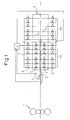
- FIG. 1 is a schematic diagram showing a cooling apparatus for carrying out the cooling method according to a first embodiment of the present invention.
- FIG. 2 is an explanatory view showing a water density distribution in the steel plate length direction at a front stage region of the cooling apparatus according to the present embodiment.
- FIG. 3 is an explanatory view showing a water density distribution in the steel plate length direction at a rear stage region of the cooling apparatus according to the present invention.
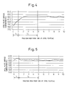
- FIG. 4 is an explanatory view showing a surface temperature distribution of the steel plate in the steel plate length direction according to the present embodiment.
- FIG. 5 is an explanatory view showing a surface temperature distribution of the steel plate on an exit side of the cooling apparatus according to the present embodiment.
- a thick-gauge steel plate rolling mill 1 is disposed.
- the cooling apparatus 4 is provided with a measuring roll 2, a steel plate position detection sensor 3, cooling nozzles 4c, three-way valves 5, flow rate adjustment valves 6, a header pipe 7, and a control unit 8.
- the cooling apparatus 4 is divided into a front stage region 4a and a rear stage region 4b.
- pluralities of cooling nozzles 4c are provided in a length direction and a width direction of the steel plate P. Further, the cooling nozzles 4c are provided at the front ends of pipes branched from the header pipe 7.
- the three-way valves 5 and the flow rate adjustment valves 6 are provided at the front stage region 4a, and the flow rate adjustment valves 6 are provided at the rear stage region 4b.
- the control unit 8 tracks the position of the steel plate P based on the detection information of the measuring roll 2 and the steel plate position detection sensor 3 and adjusts and controls the opening degrees of the three-way valves 5 and the flow rate adjustment valves 6 by this tracking information.
- the steel plate P to be cooled is divided for convenience into three regions: a front end region (region up to for example 0.5 to 2 meters from the front end of the steel plate toward the center part side in the steel plate length direction) I 1 , a front part region (region up to for example 4 to 10 meters from the boundary part of the front end region and the front part region toward the center part side in the steel plate length direction) I 2 , and a center part region (center part side region in the steel plate length direction over the boundary part of the front part region and the center part region), and the cooling water rates supplied from the cooling apparatus 4 are adjusted and controlled.
- a front end region region up to for example 0.5 to 2 meters from the front end of the steel plate toward the center part side in the steel plate length direction
- a front part region region up to for example 4 to 10 meters from the boundary part of the front end region and the front part region toward the center part side in the steel plate length direction
- a center part region center part side region in the steel plate length direction over the boundary part of the front part region and the
- the ranges of these three regions are determined according to for example the relationship between a response speed of the flow rate adjustment valves 6 and the conveyance speed of the steel plate and cooling conditions such as the water density and the temperature of the steel plate at the time of the end of the cooling. Further, they are determined by the temperature distribution of the steel plate before cooling. Further, the temperature distribution of this steel plate before cooling fluctuates due to the time for the steel plate to travel from the heating furnace, pass through the rolling mill, and reach the cooling apparatus, the rolling method, the heat conductivity of the steel plate, the material quality, and other factors.
- the control unit 8 tracks the position of the steel plate P during conveyance.
- the control of the flow rate timing valves 6 and three-way valves 5 by the control unit 8 will be explained.
- the opening degrees of the flow rate adjustment valves 6 are throttled back so that the water density becomes Q front at the front stage region 4a and rear stage region 4b of the cooling apparatus 4.
- the flow rate adjustment valves 6 and three-way valves 5 are controlled so as to open the three-way valves 5 at the front stage region 4a to an off-line side (the side out of path line of the steel plate P). Due to this, cooling water having the water density Q front is discharged to the off-line side at the front stage region 4a and is sprayed from the cooling nozzles 4c at the rear stage region 4b.
- the front end of the steel plate P enters the cooling apparatus 4, and the steel plate P successively passes between top/bottom cooling nozzles 4c.
- the three-way valves 5 at all of the cooling nozzles 4c are successively switched to the on-line side when the front end region I 1 of the steel plate P passes the cooling nozzle 4c positions (the positions where the cooling nozzles 4c are provided) and the front part region I 2 of the steel plate P reaches the cooling nozzle 4c positions so as to thereby successively start the spray of the cooling water to the steel plate P from the cooling nozzles 4c provided in the steel plate length direction.
- the opening degrees of the flow rate adjustment valves 6 are successively increased to make them fully open immediately before the front part region I 2 of the steel plate P passes. Due to this, the cooling water density of the water sprayed from the cooling nozzles 4c in the front stage region 4a successively increases from Q front and reaches the standard water density Q 0 .
- the steel plate P starts to be cooled by the entry of the front end of the steel plate P into the water sprayed from the cooling nozzles 4c with the cooling water density Q front . Then, when the front part region I 2 of the steel plate P reaches the positions of the cooling nozzles 4c, the opening degrees of the flow rate adjustment valves 6 similarly successively start to increase and become fully open immediately before the front part region I 2 passes.
- FIG. 6 is an explanatory view showing the surface temperature distribution of steel plate at the exit side of the conventional cooling apparatus.
- the temperature drop of the boundary of the masked part and non-masked part at the rear part of the thick-gauge steel plate P is smaller in comparison with the front part described above, but it is preferable to prevent this temperature drop too. This will be explained below.
- the steel plate P to be cooled is divided, for convenience, into three regions: a rear end region (region from the rear end of the steel plate toward the center part side in the steel plate length direction), rear part region (region from the rear end region toward the center part side in the steel plate length direction), and the center part region.
- the amounts of cooling water supplied from the cooling apparatus 4 are adjusted and controlled.
- the ranges of these three regions are determined according to for example the relationship between the response speed of the flow rate adjustment valves 6 and the conveyance speed of the steel plate, the water density, the temperature of the steel plate at the time of the end of the cooling, and other cooling conditions. Further, they are also determined according to the temperature distribution of the steel plate before the cooling.
- the temperature distribution of this steel plate before the cooling fluctuates due to the time for the steel plate to travel from the heating furnace, pass through the rolling mill, and reach the cooling apparatus, the rolling method, the heat conductivity, quality, etc. of the steel plate, and other factors.
- the rear part of this thick-gauge steel plate P passes through the cooling apparatus 4 in the order of the center part region, rear part region, and rear end region, so while the center part region of the thick-gauge steel plate P is passing through the front stage region 4a of the cooling apparatus 4, it is sprayed and cooled by the standard water density Q 0 , but when the rear part region of the thick-gauge steel plate P reaches the cooling nozzle 4c positions, the opening degrees of the flow rate adjustment valves 6 provided at the cooling nozzles 4c are successively throttled so that the water density becomes Q front described above before the rear end region arrives.
- the center part region of the thick-gauge steel plate P is passing the rear stage region 4b of the cooling apparatus 4, it is sprayed and cooled by the standard water density Q 0 in the same way as described above, but when the rear part region of the thick-gauge steel plate P reaches beneath the cooling nozzles 4c, the opening degrees of the flow rate adjustment valves 6 provided at the cooling nozzles 4c are successively throttled so that the water density becomes Q front described above before the rear end region arrives. Then, after that, the rear end region is sprayed and cooled in the state where those opening degrees are maintained.
- Table 1 is a table showing the plate thicknesses, plate widths, plate lengths, and temperature distributions of thick-gauge steel plates 1 to 3 before passing through the cooling apparatus.
- Table 2 is a table showing water densities and temperature distributions of thick-gauge steel plates after cooling of Examples 1 to 3 and Comparative Examples 1 and 2 in a case where thick-gauge steel plates 1 to 3 shown in Table 1 are cooled by the cooling apparatus while conveying these at a speed of 60 m/min.
- Thick-gauge steel plate 1 Thick-gauge steel plate 2 Thick-gauge steel plate 3 Plate thickness [mm] 20 20 20 Plate width [mm] 3032 2988 3010 Plate length [mm] 29542 30462 29872 Front end region Maximum value [°C] 808 809 810 Minimum value [°C] 790 793 790 Front part region Maximum value [°C] 825 827 825 Minimum value [°C] 815 816 813 Center part region Maximum value [°C] 824 825 822 Minimum value [°C] 819 816 819 Rear part region Maximum value [°C] 818 816 818 Minimum value [°C] 798 788 790 Rear end region Maximum value [°C] 786 789 790 Minimum value [°C] 775 759 762 Table 2 Ex.
- a cooling apparatus arranging cooling nozzles 4c in 24 lines in the steel plate conveyance direction (steel plate length direction) and arranging 70 cooling nozzles 4c in a direction at a right angle to the steel plate conveyance direction (steel plate width direction) is employed. Further, the front stage region 4a is made up to the 12th line of the cooling nozzles 4c, while the rear stage region 4b is made from that up to the 24th line. Further, the three-way valves, flow rate control valves, control units, etc. were given the same constitutions as those of FIG. 1 .
- the front end region I 1 of the steel plate was made 1 meter from the front end of the steel plate
- the front part region I 2 was made 4 meters from the boundary part of the front end region I 1 and the front part region I 2
- the center part region was made the part after the boundary part of the front part region I 2 and the center part region.
- Example 1 of this Table 2 is an example of a case where the present invention is not applied at the rear part region and the rear end region of the thick-gauge steel plate 1, but they are cooled with the standard water density
- Examples 2 and 3 are examples where the present invention is applied to the front part region, the front end region, the rear part region, and the rear end region.
- the water density Q front of the front stage zone when the front part region starts passing through the cooling apparatus is made, 90 vol% of the standard water density Q 0 in Example 1, 82 vol% in Example 2, and 95 vol% in Example 3, the water density of the rear stage zone when the rear part region finishes passing through the cooling apparatus is made 82 vol% of the standard water density Q 0 in Example 2 and 95 vol% in Example 3 or within a range from 80 to 95 vol%.
- Examples 1 to 3 are examples of applying the present invention.
- Example 1 is an example of a case where the water rate densities of cooling water at the front part region and the rear part region of the steel plate at the front stage and rear stage of the cooling apparatus are over the upper limit of the present invention (97 vol%)
- Comparative Example 2 is an example of a case where they are below the lower limit of the water density of the present invention (75 vol%).
- the maximum temperature difference of the steel plate after cooling became much larger in comparison with Examples 1 to 3 (27°C in Comparative Example 1 and 29°C in Comparative Example 2). Also, the shapes of the steel plates after the cooling were degraded.
- the present invention As explained above, according to the present invention, a large temperature drop of the boundary part of the masked front end region of the thick-gauge steel plate in the steel plate length direction and the front part region of the non-masked part can be suppressed, it becomes possible to make the shapes of the steel plate front end region and front part region better, and it becomes possible to suppress the change of the material quality in the steel plate length direction. Further, at the rear part of the steel plate, it becomes possible to further make the steel plate shape and material quality better. Summarizing the above, according to the present invention, the cooling uniformity in the steel plate conveyance direction is raised, and it is possible to make the material quality uniform and improve the steel plate flatness.
Landscapes
- Engineering & Computer Science (AREA)
- Mechanical Engineering (AREA)
- Chemical & Material Sciences (AREA)
- Physics & Mathematics (AREA)
- Thermal Sciences (AREA)
- Crystallography & Structural Chemistry (AREA)
- Materials Engineering (AREA)
- Metallurgy (AREA)
- Organic Chemistry (AREA)
- Heat Treatments In General, Especially Conveying And Cooling (AREA)
- Heat Treatment Of Strip Materials And Filament Materials (AREA)
Abstract
Description
- The present invention relates to a cooling method of a steel plate, more particularly relates to a cooling method of a hot rolled steel plate.
- The process of continuously cooling hot rolled steel plate by a cooling apparatus and controlling the structure of the steel plate to produce thick-gauge steel plate having high strength and high toughness is widely used. This production process contributes to reduction of the production costs by the reduction of alloying elements and to the improvement of the welding work efficiency.
- However, in this process of production, the temperatures of the front end part and the rear end part of the steel plate become lower in comparison with the center part of the steel plate in the length direction before the steel plate is transferred to the cooling apparatus. In addition, in water spray cooling in a cooling apparatus as well, there are large influences of heat transfer and heat conduction from the end surfaces, therefore an overcooling phenomenon occurs and the flatness and material properties easily become unstable.
- For this reason, for example, as disclosed in Japanese Patent Publication (A) No.
60-43435 - The overcooling prevention effect on the front end part and the rear end part of steel plate by the masking method shown in the above Japanese Patent Publication (A) No.
60-43435 - For this reason, a difference in material quality occurs in the steel plate conveyance direction (also referred to as the "steel plate longitudinal direction") inviting a drop in yield. The shape of the front end region is also easily degraded in comparison with the center part in the steel plate conveyance direction due to the influence of the temperature difference.
- An object of the present invention is to provide a novel and improved cooling method of steel plate able to raise the cooling uniformity in the steel plate conveyance direction.
- The present invention was made to solve the above problems and has as its gist the following:
- (1) A cooling method of steel plate which cools hot rolled steel plate, while conveying it in one direction, by supplying cooling water from nozzles arranged at the top and bottom in a cooling apparatus,
the cooling method of steel plate characterized by:- dividing the steel plate into a front end region, a front part region, and a center region from a head side in the conveyance direction of the steel plate and dividing the cooling apparatus into a front stage part and a rear stage part in the conveyance direction of the steel plate,
- at the front stage part of the cooling apparatus,
- not spraying any cooling water while the front end region of the steel plate is passing,
- spraying by successively increasing the amount of cooling water from 80 to 95 vol% of a standard water density when the front part region passes so that the amount of cooling water becomes the standard water density when a boundary part of the front part region and the center part region arrives,
- continuing spraying by the standard water density while the center part region is passing, then,
- at the rear stage part of the cooling apparatus,
- spraying by making the amount of
cooling water 80 to 95 vol% of the standard water density while the front end region of the steel plate is passing, - successively increasing the amount of cooling water rate from 80 to 95 vol% of the standard water density when the front part region passes so that the amount of cooling water becomes the standard water density when the boundary part of the front part region and the center part region arrives, and
- continuing spraying by the standard water density while the center part region is passing.
- (2) A cooling method of a steel plate as set forth in (1), further comprising dividing the tail end side of the above steel plate from the center part region into a rear part region and a rear end region in the conveyance direction of the steel plate and successively reducing the amount of cooling water from the standard water density at the front stage part and rear stage part of the cooling apparatus when the center part region of the steel plate finishes passing through and the rear part region is passing so as to spray an amount of cooling water becoming 80 to 95 vol% of the standard water density when the boundary part of the rear part region and the rear end region is reached and spray an amount becoming 80 to 95 vol% of the standard water density when the rear end region is passing.
- These and other objects and features of the present invention will become clearer from the following description of the preferred embodiments given with reference to the attached drawings, wherein:
-
FIG. 1 is a schematic diagram showing a cooling apparatus according to a first embodiment of the present invention; -
FIG. 2 is an explanatory view showing a water density distribution in a steel plate length direction at afront stage region 4a of the cooling apparatus according to the embodiment; -
FIG. 3 is an explanatory view showing a water density distribution in a steel plate length direction at a rear stage region of the cooling apparatus according to the embodiment; -
FIG. 4 is an explanatory view showing a surface temperature distribution of steel plate in the steel plate length direction according to the embodiment; -
FIG. 5 is an explanatory diagram showing the surface temperature distribution of steel plate at an exit side of the cooling apparatus according to the same embodiment; and -
FIG. 6 is an explanatory diagram showing the surface temperature distribution of steel plate at an exit side of a conventional cooling apparatus. - The present invention was made to solve the above problem. The means (1) characterizing it is a cooling method of steel plate which cools hot rolled steel plate, while conveying it in one direction, by supplying cooling water from nozzles arranged at the top and bottom in a cooling apparatus, the cooling method of steel plate characterized by dividing the steel plate into a front end region, a front part region, and a center region from a head side in the conveyance direction of the steel plate and dividing the cooling apparatus into a front stage part and a rear stage part in the conveyance direction of the steel plate; at the front stage part of the cooling apparatus, not spraying any cooling water while the front end region of the steel plate is passing, spraying by successively increasing the amount of cooling water from 80 to 95 vol% of a standard water density when the front part region passes so that the amount of cooling water becomes the standard water density when a boundary part of the front part region and the center part region arrives, continuing spraying by the standard water density while the center part region is passing, then; at the rear stage part of the cooling apparatus, spraying by making the amount of
cooling water 80 to 95 vol% of the standard water density while the front end region of the steel plate is passing, successively increasing the amount of cooling water rate from 80 to 95 vol% of the standard water density when the front part region passes so that the amount of cooling water becomes the standard water density when the boundary part of the front part region and the center part region arrives, and continuing spraying by the standard water density while the center part region is passing. - By such a constitution, a large temperature drop at the boundary parts of the masked front end region of the thick-gauge steel plate in the steel plate length direction and the front part region of the non-masked part can be suppressed. Further, the difference of the temperature distribution in the steel plate length direction is reduced, therefore it becomes possible to make shapes of the front and region and the front part region of the steel plate better and becomes possible to suppress changes in the material properties in the steel plate conveyance direction.
- It is also possible to divide the tail end side of the above steel plate from the center part region into a rear part region and a rear end region in the conveyance direction of the steel plate and successively reduce the amount of cooling water from the standard water density at the front stage part and rear stage part of the cooling apparatus when the center part region of the steel plate finishes passing through and the rear part region is passing so as to spray an amount of cooling water becoming 80 to 95 vol% of the standard water density when the boundary part of the rear part region and the rear end region is reached and spray an amount becoming 80 to 95 vol% of the standard water density when the rear end region is passing. By such a constitution, it becomes possible to further improve the steel plate shape and material quality also at the rear part of the thick-gauge steel plate.
- According to the present invention, the cooling uniformity in the steel plate conveyance direction can be improved.
- Below, preferred embodiments of the present invention will be explained in further detail with reference to the attached drawings. Note that in the present specification and drawings, components having substantially the same functions and constitutions are assigned the same notations and overlapping explanations are omitted.
- The inventors conducted various experiments and studies on the method of forced cooling hot rolled thick-gauge steel plate is divided by cooling water suppress the temperature drop at the boundary part of the masked part and the non-masked part at the front part of the thick-gauge steel plate since that temperature drop is large (about 1.5 times the rear part), where the cooling apparatus into a front stage region and a rear stage region and the front end part and rear end part of the thick-gauge steel plate are masked by ON/OFF control of the cooling water by three-way valves.
- In order to suppress this temperature drop at the boundary part, it is necessary to set a flow rate adjustment valve able to adjust the flow rate in piping for supplying the cooling water to cooling nozzles in the cooling apparatus and successively increase the amount of cooling water at the boundary part. However, the region of the temperature drop at the boundary part is a short 2 to 3 meters or less, and the valve opening time of a flow rate adjustment valve (time from fully closed to fully open) is about 10 seconds even at the fastest. In addition, the steel plate conveyance speed (1.0 to 2.0 m/s) can not be reduced.
- For this reason, as described above, if successively increasing the opening of the flow rate adjustment valve from fully closed to fully open, the timing when the flow rate adjustment valve becomes fully open greatly overshoots the temperature drop region and becomes the center part side of the steel plate in the conveyance direction. The new problem arises that the temperature rises at the front region of the center part where the temperature had been sound (region with no temperature drop).
- Further, the present inventors proceeded with detailed investigations, experiments, and studies and consequently discovered that the temperature drop of the boundary part described above is almost always 15 to 30°C or so and that even if not successively increasing the opening degree of the flow rate adjustment valve from fully closed to fully open, if successively opening the valve from the opening degree giving 80 to 95 vol% of the standard water density (amount of water per unit area and unit time supplied to center part of steel plate (unit: m3(m2·min)) Q0 (hereinafter this water density referred to as Qfront) so as to set the standard water density Q0, it is possible to suppress the temperature drop of the above boundary part to an extent causing no problem in actual operation without any accompanying rise in temperature of the above sound part.
- Note that the standard water density Q0 is for example preferably made a range from 0.3 to 1.5 m3/(m2·min) in the case of thick-gauge steel plate. Namely, in thick-gauge steel plate using a water density where this standard water density Q0 is for example more than 1.5 m3/(m2·min), the temperature at the time of the end of cooling is low in many cases and the surface temperature of the thick-gauge steel plate during cooling also becomes low. For this reason, when cooling such thick-gauge steel plate, the cooling mostly becomes cooling in the nucleate boiling region where the cooling becomes stable, therefore the temperature difference after cooling rarely becomes large, there is almost never any adverse influence due to the temperature difference. The frequency of use in the present invention is therefore low. On the other hand, with a water density where the standard water density Q0 is for example less than 0.3 m3/(m2·min), the cooling rate becomes low, therefore coarsening of the grain of the thick-gauge steel plate can be prevented, but the strength of the thick-gauge steel plate cannot be improved, so the frequency of use of a water density of less than 0.3 m3/(m2·min) is low. Therefore, the applicability of the present invention is low.
- Note that the standard water density Q0 is mainly determined by the quality of the cooled steel plate. Other than this, it is determined by the temperature difference between the temperature of the steel plate before the cooling by the cooling apparatus and the target temperature of the steel plate after cooling, the heat conductivity of the steel plate, the cooling nozzles and other cooling forms and various other factors. Further, the temperature of the steel plate before cooling fluctuates according to the time for the steel plate to travel from the heating furnace, pass through the rolling mill, and reach the cooling apparatus, the rolling method, and other factors.
- The present invention was made based on these findings and is explained in detail with reference to
FIG. 1 to FIG. 5 .FIG. 1 is a schematic diagram showing a cooling apparatus for carrying out the cooling method according to a first embodiment of the present invention.FIG. 2 is an explanatory view showing a water density distribution in the steel plate length direction at a front stage region of the cooling apparatus according to the present embodiment.FIG. 3 is an explanatory view showing a water density distribution in the steel plate length direction at a rear stage region of the cooling apparatus according to the present invention.FIG. 4 is an explanatory view showing a surface temperature distribution of the steel plate in the steel plate length direction according to the present embodiment.FIG. 5 is an explanatory view showing a surface temperature distribution of the steel plate on an exit side of the cooling apparatus according to the present embodiment. - As shown in
FIG. 1 , adjoining thecooling apparatus 4 according to the present embodiment, a thick-gauge steelplate rolling mill 1 is disposed. Thecooling apparatus 4 is provided with a measuringroll 2, a steel plateposition detection sensor 3, cooling nozzles 4c, three-way valves 5, flowrate adjustment valves 6, aheader pipe 7, and acontrol unit 8. Thecooling apparatus 4 is divided into afront stage region 4a and a rear stage region 4b. In order for the cooling nozzles to spray cooling water on the top surface and the bottom surface of steel plate P to be cooled, pluralities of cooling nozzles 4c are provided in a length direction and a width direction of the steel plate P. Further, the cooling nozzles 4c are provided at the front ends of pipes branched from theheader pipe 7. In the middle of the pipes, the three-way valves 5 and the flowrate adjustment valves 6 are provided at thefront stage region 4a, and the flowrate adjustment valves 6 are provided at the rear stage region 4b. Thecontrol unit 8 tracks the position of the steel plate P based on the detection information of the measuringroll 2 and the steel plateposition detection sensor 3 and adjusts and controls the opening degrees of the three-way valves 5 and the flowrate adjustment valves 6 by this tracking information. - Further, the steel plate P to be cooled is divided for convenience into three regions: a front end region (region up to for example 0.5 to 2 meters from the front end of the steel plate toward the center part side in the steel plate length direction) I1, a front part region (region up to for example 4 to 10 meters from the boundary part of the front end region and the front part region toward the center part side in the steel plate length direction) I2, and a center part region (center part side region in the steel plate length direction over the boundary part of the front part region and the center part region), and the cooling water rates supplied from the
cooling apparatus 4 are adjusted and controlled. The ranges of these three regions are determined according to for example the relationship between a response speed of the flowrate adjustment valves 6 and the conveyance speed of the steel plate and cooling conditions such as the water density and the temperature of the steel plate at the time of the end of the cooling. Further, they are determined by the temperature distribution of the steel plate before cooling. Further, the temperature distribution of this steel plate before cooling fluctuates due to the time for the steel plate to travel from the heating furnace, pass through the rolling mill, and reach the cooling apparatus, the rolling method, the heat conductivity of the steel plate, the material quality, and other factors. - In the present embodiment, first, when the steel plate P to be cooled passing through the rolling
mill 1 and finished being hot rolled moves on a path line toward thecooling apparatus 4, the front end of the steel plate P is detected by the steel plateposition detection sensor 3. Then, the detection information of the front end of the steel plate P is input to thecontrol unit 8. Next, the measuringroll 2 finds the movement distance of the steel plate P and inputs the movement distance to thecontrol unit 8. Using these two input information, thecontrol unit 8 tracks the position of the steel plate P during conveyance. - Next, the control of the flow
rate timing valves 6 and three-way valves 5 by thecontrol unit 8 will be explained. First, before the front end of the steel plate P enters thecooling apparatus 4, the opening degrees of the flowrate adjustment valves 6 are throttled back so that the water density becomes Qfront at thefront stage region 4a and rear stage region 4b of thecooling apparatus 4. Further, the flowrate adjustment valves 6 and three-way valves 5 are controlled so as to open the three-way valves 5 at thefront stage region 4a to an off-line side (the side out of path line of the steel plate P). Due to this, cooling water having the water density Qfront is discharged to the off-line side at thefront stage region 4a and is sprayed from the cooling nozzles 4c at the rear stage region 4b. - In this state, the front end of the steel plate P enters the
cooling apparatus 4, and the steel plate P successively passes between top/bottom cooling nozzles 4c. At this time, at thefront stage region 4a of thecooling apparatus 4, the three-way valves 5 at all of the cooling nozzles 4c are successively switched to the on-line side when the front end region I1 of the steel plate P passes the cooling nozzle 4c positions (the positions where the cooling nozzles 4c are provided) and the front part region I2 of the steel plate P reaches the cooling nozzle 4c positions so as to thereby successively start the spray of the cooling water to the steel plate P from the cooling nozzles 4c provided in the steel plate length direction. Then, from immediately after that to when the front part region I2 of the steel plate P has passed the cooling nozzle 4c positions, the opening degrees of the flowrate adjustment valves 6 are successively increased to make them fully open immediately before the front part region I2 of the steel plate P passes. Due to this, the cooling water density of the water sprayed from the cooling nozzles 4c in thefront stage region 4a successively increases from Qfront and reaches the standard water density Q0. - On the other hand, at the rear stage region 4b of the
cooling apparatus 4, the steel plate P starts to be cooled by the entry of the front end of the steel plate P into the water sprayed from the cooling nozzles 4c with the cooling water density Qfront. Then, when the front part region I2 of the steel plate P reaches the positions of the cooling nozzles 4c, the opening degrees of the flowrate adjustment valves 6 similarly successively start to increase and become fully open immediately before the front part region I2 passes. - Due to such a cooling method, for example, when the front part of the thick-gauge steel plate P has the temperature shown in
FIG. 4 , the water density of the cooling water sprayed from the cooling nozzles 4c at thefront stage region 4a of thecooling apparatus 4 becomes as shown inFIG. 2 , while the water density of the cooling water sprayed from the cooling nozzles 4c at the rear stage region 4b of thecooling apparatus 4 becomes as shown inFIG. 3 . As a result of this, the temperature of the steel plate P exiting thecooling apparatus 4 exhibits a good temperature distribution as shown inFIG. 5 . On the other hand, when only controlling masking to stop the spray of water at the front end region without using the present invention, the temperature difference at the boundary of the front end region and the front part region is large as shown inFIG. 6 . Note thatFIG. 6 is an explanatory view showing the surface temperature distribution of steel plate at the exit side of the conventional cooling apparatus. - Next, the method of cooling the rear part of the thick-gauge steel plate P according to the present embodiment will be explained. The temperature drop of the boundary of the masked part and non-masked part at the rear part of the thick-gauge steel plate P is smaller in comparison with the front part described above, but it is preferable to prevent this temperature drop too. This will be explained below.
- The steel plate P to be cooled is divided, for convenience, into three regions: a rear end region (region from the rear end of the steel plate toward the center part side in the steel plate length direction), rear part region (region from the rear end region toward the center part side in the steel plate length direction), and the center part region. The amounts of cooling water supplied from the
cooling apparatus 4 are adjusted and controlled. The ranges of these three regions are determined according to for example the relationship between the response speed of the flowrate adjustment valves 6 and the conveyance speed of the steel plate, the water density, the temperature of the steel plate at the time of the end of the cooling, and other cooling conditions. Further, they are also determined according to the temperature distribution of the steel plate before the cooling. The temperature distribution of this steel plate before the cooling fluctuates due to the time for the steel plate to travel from the heating furnace, pass through the rolling mill, and reach the cooling apparatus, the rolling method, the heat conductivity, quality, etc. of the steel plate, and other factors. - The rear part of this thick-gauge steel plate P passes through the
cooling apparatus 4 in the order of the center part region, rear part region, and rear end region, so while the center part region of the thick-gauge steel plate P is passing through thefront stage region 4a of thecooling apparatus 4, it is sprayed and cooled by the standard water density Q0, but when the rear part region of the thick-gauge steel plate P reaches the cooling nozzle 4c positions, the opening degrees of the flowrate adjustment valves 6 provided at the cooling nozzles 4c are successively throttled so that the water density becomes Qfront described above before the rear end region arrives. Then, when the rear end region reaches the cooling nozzle 4c positions, the three-way valves 5 are switched to the off-line side, the cooling water is discharged to the off-line side, and the spray of cooling water to the rear end region is stopped. This operation is successively performed along with movement to the rear part of the thick-gauge steel plate P for the cooling nozzles 4c from the entry side of thecooling apparatus 4 to the exit side direction. Further, while the center part region of the thick-gauge steel plate P is passing the rear stage region 4b of thecooling apparatus 4, it is sprayed and cooled by the standard water density Q0 in the same way as described above, but when the rear part region of the thick-gauge steel plate P reaches beneath the cooling nozzles 4c, the opening degrees of the flowrate adjustment valves 6 provided at the cooling nozzles 4c are successively throttled so that the water density becomes Qfront described above before the rear end region arrives. Then, after that, the rear end region is sprayed and cooled in the state where those opening degrees are maintained. - Examples of the present invention will be explained together with comparative examples with reference to Table 1 and Table 2. Table 1 is a table showing the plate thicknesses, plate widths, plate lengths, and temperature distributions of thick-
gauge steel plates 1 to 3 before passing through the cooling apparatus. Table 2 is a table showing water densities and temperature distributions of thick-gauge steel plates after cooling of Examples 1 to 3 and Comparative Examples 1 and 2 in a case where thick-gauge steel plates 1 to 3 shown in Table 1 are cooled by the cooling apparatus while conveying these at a speed of 60 m/min.Table 1 Thick- gauge steel plate 1Thick- gauge steel plate 2Thick- gauge steel plate 3Plate thickness [mm] 20 20 20 Plate width [mm] 3032 2988 3010 Plate length [mm] 29542 30462 29872 Front end region Maximum value [°C] 808 809 810 Minimum value [°C] 790 793 790 Front part region Maximum value [°C] 825 827 825 Minimum value [°C] 815 816 813 Center part region Maximum value [°C] 824 825 822 Minimum value [°C] 819 816 819 Rear part region Maximum value [°C] 818 816 818 Minimum value [°C] 798 788 790 Rear end region Maximum value [°C] 786 789 790 Minimum value [°C] 775 759 762 Table 2 Ex. 1 Ex. 2 Ex. 3 Comp. Ex. 1 Comp. Ex. 2 Thick-gauge steel plate No 1 2 3 2 3 water rate density [m3/ (m2·.min)] Front end region Cooling apparatus front stage 0 0 0 0 0 Cooling apparatus rear stage 0.54 0.49 0.57 0.582 0.45 Front part region Cooling apparatus front stage 0.54 → 0.6 0.49 → 0.6 0.57 → 0.6 0.582 → 0.6 0.45 → 0.6 Cooling apparatus rear stage (wt%) 0.54 → 0.6 0.49 → 0.6 0.57 → 0.6 0.582 → 0.6 0.95 → 0.6 (90%→100%) (82%→100%) (95%→100%) (97%→100%) (75%→100%) Center part region Cooling apparatus front stage 0.6 0.6 0.6 0.6 0.6 Cooling apparatus rear stage 0.6 0.6 0.6 0.6 0.6 Rear part region Cooling apparatus front stage 0.6 0.6 → 0.49 0.6 → 0.57 0.6 → 0.582 0.6 → 0.45 Cooling apparatus rear stage (wt%) 0.6 0.6 → 0.49 0.6 → 0.57 0.6 → 0.582 0.6 → 0.45 100% (100%→82%) (100%→95%) (100%-97%) (100%-75%) Rear end region Cooling apparatus front stage 0 0 0 0 0 Cooling apparatus rear stage 0.6 0.49 0.57 0.582 0.45 Temp. after cooling [°C] Front end region Maximum value 611 621 604 601 630 Minimum value 604 617 599 594 620 Front part region Maximum value 605 620 610 604 623 Minimum value 603 606 590 579 607 Center part region Maximum value 606 606 606 606 606 Minimum value 601 601 601 601 601 Rear part region Maximum value 615 611 603 602 624 Minimum value 602 607 595 588 618 Rear end region Maximum value 621 613 600 598 620 Minimum value 604 610 593 591 615 Maximum temperature difference [°C] 17 20 20 27 29 - In the examples of the present invention, a cooling apparatus arranging cooling nozzles 4c in 24 lines in the steel plate conveyance direction (steel plate length direction) and arranging 70 cooling nozzles 4c in a direction at a right angle to the steel plate conveyance direction (steel plate width direction) is employed. Further, the
front stage region 4a is made up to the 12th line of the cooling nozzles 4c, while the rear stage region 4b is made from that up to the 24th line. Further, the three-way valves, flow rate control valves, control units, etc. were given the same constitutions as those ofFIG. 1 . Further, the front end region I1 of the steel plate was made 1 meter from the front end of the steel plate, the front part region I2 was made 4 meters from the boundary part of the front end region I1 and the front part region I2, and the center part region was made the part after the boundary part of the front part region I2 and the center part region. - Example 1 of this Table 2 is an example of a case where the present invention is not applied at the rear part region and the rear end region of the thick-
gauge steel plate 1, but they are cooled with the standard water density, Examples 2 and 3 are examples where the present invention is applied to the front part region, the front end region, the rear part region, and the rear end region. Further, the water density Qfront of the front stage zone when the front part region starts passing through the cooling apparatus is made, 90 vol% of the standard water density Q0 in Example 1, 82 vol% in Example 2, and 95 vol% in Example 3, the water density of the rear stage zone when the rear part region finishes passing through the cooling apparatus is made 82 vol% of the standard water density Q0 in Example 2 and 95 vol% in Example 3 or within a range from 80 to 95 vol%. Examples 1 to 3 are examples of applying the present invention. - In Examples 1 to 3, as shown in the row of the maximum temperature difference of Table 2, the maximum temperature difference, representing the difference of the minimum value and the maximum value of the temperature distribution of the steel plate after cooling, became a small 20°C or less in all examples. On the other hand, Comparative Example 1 is an example of a case where the water rate densities of cooling water at the front part region and the rear part region of the steel plate at the front stage and rear stage of the cooling apparatus are over the upper limit of the present invention (97 vol%), and Comparative Example 2 is an example of a case where they are below the lower limit of the water density of the present invention (75 vol%). In both cases, the maximum temperature difference of the steel plate after cooling became much larger in comparison with Examples 1 to 3 (27°C in Comparative Example 1 and 29°C in Comparative Example 2). Also, the shapes of the steel plates after the cooling were degraded.
- As explained above, according to the present invention, a large temperature drop of the boundary part of the masked front end region of the thick-gauge steel plate in the steel plate length direction and the front part region of the non-masked part can be suppressed, it becomes possible to make the shapes of the steel plate front end region and front part region better, and it becomes possible to suppress the change of the material quality in the steel plate length direction. Further, at the rear part of the steel plate, it becomes possible to further make the steel plate shape and material quality better. Summarizing the above, according to the present invention, the cooling uniformity in the steel plate conveyance direction is raised, and it is possible to make the material quality uniform and improve the steel plate flatness.
- Above, preferred embodiments of the present invention were explained with reference to the attached drawings, but needless to say the present invention is not limited to these examples. It is clear to those skilled in the art that various modifications or corrections may be conceived of within the scope of the claims. It is understood that these also naturally are included in the technical scope of the invention.
Claims (2)
- A cooling method of steel plate which cools hot rolled steel plate, while conveying it in one direction, by supplying cooling water from nozzles arranged at the top and bottom in a cooling apparatus,
said cooling method of steel plate characterized by:dividing said steel plate into a front end region, a front part region, and a center region from a head side in the conveyance direction of said steel plate and dividing said cooling apparatus into a front stage part and a rear stage part in the conveyance direction of said steel plate,at said front stage part of said cooling apparatus,not spraying any cooling water while said front end region of said steel plate is passing,spraying by successively increasing said amount of cooling water from 80 to 95 vol% of a standard water density when said front part region passes so that said amount of cooling water becomes said standard water density when a boundary part of said front part region and said center part region arrives,continuing spraying by said standard water density while the center part region is passing, then,at said rear stage part of said cooling apparatus,spraying by making said amount of cooling water 80 to 95 vol% of the standard water density while said front end region of said steel plate is passing,successively increasing said amount of cooling water rate from 80 to 95 vol% of said standard water density when said front part region passes so that said amount of cooling water becomes said standard water density when the boundary part of said front part region and said center part region arrives, andcontinuing spraying by said standard water density while the center part region is passing. - A cooling method of a steel plate as set forth in claim 1, further comprising dividing the tail end side of the above steel plate from the center part region into a rear part region and a rear end region in the conveyance direction of the steel plate and successively reducing the amount of cooling water from the standard water density at the front stage part and rear stage part of the cooling apparatus when the center part region of the steel plate finishes passing through and the rear part region is passing so as to spray an amount of cooling water becoming 80 to 95 vol% of the standard water density when the boundary part of the rear part region and the rear end region is reached and spray an amount becoming 80 to 95 vol% of the standard water density when the rear end region is passing.
Applications Claiming Priority (2)
| Application Number | Priority Date | Filing Date | Title |
|---|---|---|---|
| JP2006223636A JP4119928B2 (en) | 2006-08-18 | 2006-08-18 | Steel plate cooling method |
| PCT/JP2007/065320 WO2008020549A1 (en) | 2006-08-18 | 2007-07-31 | Method of cooling steel sheet |
Publications (3)
| Publication Number | Publication Date |
|---|---|
| EP1925373A1 true EP1925373A1 (en) | 2008-05-28 |
| EP1925373A4 EP1925373A4 (en) | 2008-08-27 |
| EP1925373B1 EP1925373B1 (en) | 2010-03-31 |
Family
ID=39082075
Family Applications (1)
| Application Number | Title | Priority Date | Filing Date |
|---|---|---|---|
| EP07791993A Active EP1925373B1 (en) | 2006-08-18 | 2007-07-31 | Method of cooling steel sheet |
Country Status (10)
| Country | Link |
|---|---|
| US (1) | US8282747B2 (en) |
| EP (1) | EP1925373B1 (en) |
| JP (1) | JP4119928B2 (en) |
| KR (1) | KR100882931B1 (en) |
| CN (1) | CN101378856B (en) |
| BR (1) | BRPI0702830A2 (en) |
| DE (1) | DE602007005581D1 (en) |
| RU (1) | RU2386505C1 (en) |
| TW (1) | TW200810851A (en) |
| WO (1) | WO2008020549A1 (en) |
Cited By (1)
| Publication number | Priority date | Publication date | Assignee | Title |
|---|---|---|---|---|
| EP2982453A1 (en) * | 2014-08-06 | 2016-02-10 | Primetals Technologies Austria GmbH | Adjustment of a targeted temperature profile on the strip head and strip foot before transversally cutting a metal strip |
Families Citing this family (20)
| Publication number | Priority date | Publication date | Assignee | Title |
|---|---|---|---|---|
| DE102007046279A1 (en) * | 2007-09-27 | 2009-04-09 | Siemens Ag | Operating method for a cooling line with centralized detection of valve characteristics and objects corresponding thereto |
| US8359894B2 (en) * | 2009-12-16 | 2013-01-29 | Nippon Steel Corporation | Method for cooling hot-rolled steel strip |
| CN101954382B (en) * | 2010-07-15 | 2012-05-30 | 首钢总公司 | High-speed wire rod water-cooling reverse control method |
| CN102759935A (en) * | 2011-04-25 | 2012-10-31 | 蔺桃 | Novel cooling control method |
| JP5950661B2 (en) * | 2012-04-09 | 2016-07-13 | 新日鐵住金株式会社 | Method and method for cooling hot-rolled steel sheet |
| KR101370506B1 (en) * | 2012-07-06 | 2014-03-06 | 주식회사 포스코 | Accelerated cooling apparatus for thermo-mechanical control process |
| CN104801551B (en) * | 2014-01-23 | 2017-06-23 | 宝山钢铁股份有限公司 | A kind of hot continuous rolling slab reeling temperature controlling method |
| CN105013841B (en) * | 2015-07-22 | 2017-05-17 | 中冶南方工程技术有限公司 | Strip steel cooling system |
| CN105032958B (en) * | 2015-08-24 | 2018-04-20 | 东北大学 | Using the instant cooling system and cooling means of cooling technique controlled rolling between passage |
| WO2018055918A1 (en) * | 2016-09-23 | 2018-03-29 | 新日鐵住金株式会社 | Device and method for cooling hot-rolled steel sheet |
| CN106311763B (en) * | 2016-10-25 | 2019-04-26 | 东北大学 | An annular jet cooling device for controlled cooling of a hot-rolled seamless steel pipe |
| CN106269932A (en) * | 2016-10-25 | 2017-01-04 | 东北大学 | A kind of hot rolled seamless steel tube On-line Control cooling device |
| TWI680813B (en) * | 2017-04-17 | 2020-01-01 | 日商日本製鐵股份有限公司 | Cooling device for hot-rolled steel sheet, and method of cooling hot-rolled steel sheet |
| ES3002688T3 (en) * | 2018-06-13 | 2025-03-07 | Novelis Inc | Systems and methods for quenching a metal strip after rolling |
| CN110316511A (en) * | 2019-06-05 | 2019-10-11 | 浙江长兴鼎昌金属制品有限公司 | A kind of energy-saving equipment producing cooling conveying for stainless steel |
| CN111069308A (en) * | 2019-12-09 | 2020-04-28 | 北京科技大学 | A method for improving the uniformity of on-line accelerated cooling of medium and thick plates |
| DE102020201784B4 (en) * | 2020-02-13 | 2024-10-10 | Schlüter Automation und Sensorik GmbH | Material tracking device for tracking rolled plates in a cooling section with a plurality of water nozzles in a hot rolling mill, method for operating a material tracking device, cooling system for intensive cooling of rolled plates during the production of sheets in a hot rolling mill and method for operating a cooling system |
| DE102020205252A1 (en) | 2020-04-24 | 2021-10-28 | Kocks Technik Gmbh & Co Kg | Long product cooling device and method for long product cooling using the same |
| CN115702048A (en) * | 2020-06-04 | 2023-02-14 | 新布里萨什肯联铝业 | Cooling method and equipment for reversing hot rolling mill |
| CN117399434A (en) * | 2023-08-30 | 2024-01-16 | 宝武集团鄂城钢铁有限公司 | A method and system for improving the opening accuracy of the descaling valve in the steel rolling system |
Family Cites Families (12)
| Publication number | Priority date | Publication date | Assignee | Title |
|---|---|---|---|---|
| GB806786A (en) | 1955-10-11 | 1958-12-31 | British Thomson Houston Co Ltd | Improvements in and relating to cooling equipment |
| JPS6043435A (en) | 1983-08-17 | 1985-03-08 | Nippon Steel Corp | Method and device for cooling hot-rolled steel plate |
| JPS6068107A (en) | 1983-09-24 | 1985-04-18 | Kawasaki Steel Corp | Method and device for cooling hot rolled steel sheet |
| JPS60174833A (en) * | 1984-02-20 | 1985-09-09 | Nippon Steel Corp | Cooling method of hot steel sheet |
| BE900784A (en) | 1984-10-09 | 1985-04-09 | Centre Rech Metallurgique | DEVICE FOR COOLING A MOVING METAL PRODUCT AND INSTALLATION COMPRISING THE APPLICATION. |
| JPS62127116A (en) * | 1985-11-27 | 1987-06-09 | Mitsubishi Electric Corp | Steel plate cooling device |
| SU1435348A1 (en) * | 1985-12-02 | 1988-11-07 | Киевский институт автоматики им.ХХУ съезда КПСС | Method of accelerated cooling of rolled stock |
| JPS62130222A (en) | 1985-12-03 | 1987-06-12 | Nippon Steel Corp | Method and apparatus for cooling hot steel sheet |
| JP2610019B2 (en) | 1986-07-03 | 1997-05-14 | 新日本製鐵株式会社 | Cooling method of hot steel plate |
| JPH07185631A (en) * | 1993-12-28 | 1995-07-25 | Kobe Steel Ltd | Winding temperature control method for hot rolled steel sheet |
| JPH08309425A (en) * | 1995-05-23 | 1996-11-26 | Sumitomo Metal Ind Ltd | Cooling control method for hot rolled steel sheet |
| JP4403083B2 (en) | 2005-01-17 | 2010-01-20 | 新日本製鐵株式会社 | Controlled cooling method for steel sheet |
-
2006
- 2006-08-18 JP JP2006223636A patent/JP4119928B2/en active Active
-
2007
- 2007-07-31 WO PCT/JP2007/065320 patent/WO2008020549A1/en not_active Ceased
- 2007-07-31 BR BRPI0702830-0A patent/BRPI0702830A2/en active IP Right Grant
- 2007-07-31 KR KR1020087016005A patent/KR100882931B1/en active Active
- 2007-07-31 RU RU2008131698/02A patent/RU2386505C1/en active
- 2007-07-31 DE DE602007005581T patent/DE602007005581D1/en active Active
- 2007-07-31 TW TW096127992A patent/TW200810851A/en unknown
- 2007-07-31 US US12/223,367 patent/US8282747B2/en active Active
- 2007-07-31 EP EP07791993A patent/EP1925373B1/en active Active
- 2007-07-31 CN CN200780004189XA patent/CN101378856B/en active Active
Cited By (3)
| Publication number | Priority date | Publication date | Assignee | Title |
|---|---|---|---|---|
| EP2982453A1 (en) * | 2014-08-06 | 2016-02-10 | Primetals Technologies Austria GmbH | Adjustment of a targeted temperature profile on the strip head and strip foot before transversally cutting a metal strip |
| WO2016020134A1 (en) * | 2014-08-06 | 2016-02-11 | Primetals Technologies Austria GmbH | Adjusting a targeted temperature profile at the strip head and strip base prior to cross-cutting a metal strip |
| US10870139B2 (en) | 2014-08-06 | 2020-12-22 | Primetals Technologies Austria GmbH | Adjusting a targeted temperature profile at the strip head and strip base prior to cross-cutting a metal strip |
Also Published As
| Publication number | Publication date |
|---|---|
| JP2008043988A (en) | 2008-02-28 |
| JP4119928B2 (en) | 2008-07-16 |
| RU2386505C1 (en) | 2010-04-20 |
| CN101378856A (en) | 2009-03-04 |
| RU2008131698A (en) | 2010-02-10 |
| DE602007005581D1 (en) | 2010-05-12 |
| WO2008020549A1 (en) | 2008-02-21 |
| KR100882931B1 (en) | 2009-02-10 |
| US20090194207A1 (en) | 2009-08-06 |
| EP1925373A4 (en) | 2008-08-27 |
| TWI322049B (en) | 2010-03-21 |
| TW200810851A (en) | 2008-03-01 |
| EP1925373B1 (en) | 2010-03-31 |
| CN101378856B (en) | 2011-08-17 |
| BRPI0702830A2 (en) | 2011-03-15 |
| US8282747B2 (en) | 2012-10-09 |
| KR20080089578A (en) | 2008-10-07 |
Similar Documents
| Publication | Publication Date | Title |
|---|---|---|
| EP1925373B1 (en) | Method of cooling steel sheet | |
| JP5218435B2 (en) | Controlled cooling method for thick steel plate | |
| EP2465620B1 (en) | Method for cooling hot-rolled steel strip | |
| EP2116313B1 (en) | Device and method for cooling hot-rolled steel strip | |
| EP2072157B1 (en) | Method of cooling hot-rolled steel strip | |
| JP4604564B2 (en) | Method and apparatus for controlling cooling of thick steel plate | |
| JP6816772B2 (en) | Cooling device and cooling method for hot-rolled steel sheet | |
| EP3825019B1 (en) | Cooling device for hot-rolled steel sheet and cooling method of hot-rolled steel sheet | |
| EP1992426B1 (en) | Cooling apparatus for hot rolled steel band and method of cooling the steel band | |
| JP6569843B1 (en) | Thick steel plate cooling device and cooling method, and thick steel plate manufacturing equipment and manufacturing method | |
| JP5327140B2 (en) | Method for cooling hot rolled steel sheet | |
| WO2007026905A1 (en) | Hot rolling facility of steel plate and hot rolling method | |
| US20200377967A1 (en) | Steel material cooling device and cooling method | |
| JP3189732B2 (en) | Cooling method for hot steel sheet and cooling device for hot steel sheet | |
| JP4709615B2 (en) | Method for cooling hot rolled steel sheet | |
| KR100973915B1 (en) | Rolled Sheet Cooling Method | |
| JP2979913B2 (en) | Metal strip cooling device | |
| JP4653623B2 (en) | Steel sheet cooling control method | |
| JP4682669B2 (en) | H-shaped steel cooling equipment and cooling method | |
| JPS61219412A (en) | Uniform cooling method of hot steel plate and its apparatus | |
| JPH10291018A (en) | Method for cooling high-temperature steel sheet and device for cooling high-temperature steel sheet |
Legal Events
| Date | Code | Title | Description |
|---|---|---|---|
| PUAI | Public reference made under article 153(3) epc to a published international application that has entered the european phase |
Free format text: ORIGINAL CODE: 0009012 |
|
| 17P | Request for examination filed |
Effective date: 20080313 |
|
| AK | Designated contracting states |
Kind code of ref document: A1 Designated state(s): AT BE BG CH CY CZ DE DK EE ES FI FR GB GR HU IE IS IT LI LT LU LV MC MT NL PL PT RO SE SI SK TR |
|
| AX | Request for extension of the european patent |
Extension state: AL BA HR MK RS |
|
| A4 | Supplementary search report drawn up and despatched |
Effective date: 20080730 |
|
| RIC1 | Information provided on ipc code assigned before grant |
Ipc: B21B 37/76 20060101ALI20080724BHEP Ipc: C21D 1/00 20060101ALI20080724BHEP Ipc: B21B 45/02 20060101AFI20080403BHEP |
|
| 17Q | First examination report despatched |
Effective date: 20081121 |
|
| RBV | Designated contracting states (corrected) |
Designated state(s): BE DE FI FR GB SE |
|
| GRAP | Despatch of communication of intention to grant a patent |
Free format text: ORIGINAL CODE: EPIDOSNIGR1 |
|
| DAX | Request for extension of the european patent (deleted) | ||
| GRAS | Grant fee paid |
Free format text: ORIGINAL CODE: EPIDOSNIGR3 |
|
| GRAA | (expected) grant |
Free format text: ORIGINAL CODE: 0009210 |
|
| AK | Designated contracting states |
Kind code of ref document: B1 Designated state(s): BE DE FI FR GB SE |
|
| REG | Reference to a national code |
Ref country code: GB Ref legal event code: FG4D |
|
| REF | Corresponds to: |
Ref document number: 602007005581 Country of ref document: DE Date of ref document: 20100512 Kind code of ref document: P |
|
| REG | Reference to a national code |
Ref country code: SE Ref legal event code: TRGR |
|
| PLBI | Opposition filed |
Free format text: ORIGINAL CODE: 0009260 |
|
| PLAX | Notice of opposition and request to file observation + time limit sent |
Free format text: ORIGINAL CODE: EPIDOSNOBS2 |
|
| 26 | Opposition filed |
Opponent name: SIEMENS VAI METALS TECHNOLOGIES LTD. Effective date: 20101223 Opponent name: CENTRE DE RECHERCHES METALLURGIQUES ASBL Effective date: 20101223 |
|
| PLBB | Reply of patent proprietor to notice(s) of opposition received |
Free format text: ORIGINAL CODE: EPIDOSNOBS3 |
|
| REG | Reference to a national code |
Ref country code: DE Ref legal event code: R100 Ref document number: 602007005581 Country of ref document: DE |
|
| PLCK | Communication despatched that opposition was rejected |
Free format text: ORIGINAL CODE: EPIDOSNREJ1 |
|
| RAP2 | Party data changed (patent owner data changed or rights of a patent transferred) |
Owner name: NIPPON STEEL & SUMITOMO METAL CORPORATION |
|
| PLBN | Opposition rejected |
Free format text: ORIGINAL CODE: 0009273 |
|
| STAA | Information on the status of an ep patent application or granted ep patent |
Free format text: STATUS: OPPOSITION REJECTED |
|
| 27O | Opposition rejected |
Effective date: 20121025 |
|
| REG | Reference to a national code |
Ref country code: DE Ref legal event code: R082 Ref document number: 602007005581 Country of ref document: DE Representative=s name: VOSSIUS & PARTNER, DE Effective date: 20130227 Ref country code: DE Ref legal event code: R081 Ref document number: 602007005581 Country of ref document: DE Owner name: NIPPON STEEL & SUMITOMO METAL CORPORATION, JP Free format text: FORMER OWNER: NIPPON STEEL CORP., TOKIO/TOKYO, JP Effective date: 20130227 Ref country code: DE Ref legal event code: R082 Ref document number: 602007005581 Country of ref document: DE Representative=s name: VOSSIUS & PARTNER PATENTANWAELTE RECHTSANWAELT, DE Effective date: 20130227 |
|
| REG | Reference to a national code |
Ref country code: DE Ref legal event code: R100 Ref document number: 602007005581 Country of ref document: DE Effective date: 20121025 |
|
| REG | Reference to a national code |
Ref country code: FR Ref legal event code: PLFP Year of fee payment: 10 |
|
| REG | Reference to a national code |
Ref country code: FR Ref legal event code: PLFP Year of fee payment: 11 |
|
| REG | Reference to a national code |
Ref country code: FR Ref legal event code: PLFP Year of fee payment: 12 |
|
| REG | Reference to a national code |
Ref country code: DE Ref legal event code: R082 Ref document number: 602007005581 Country of ref document: DE Representative=s name: VOSSIUS & PARTNER PATENTANWAELTE RECHTSANWAELT, DE Ref country code: DE Ref legal event code: R081 Ref document number: 602007005581 Country of ref document: DE Owner name: NIPPON STEEL CORPORATION, JP Free format text: FORMER OWNER: NIPPON STEEL & SUMITOMO METAL CORPORATION, TOKYO, JP |
|
| PGFP | Annual fee paid to national office [announced via postgrant information from national office to epo] |
Ref country code: GB Payment date: 20250612 Year of fee payment: 19 |
|
| PGFP | Annual fee paid to national office [announced via postgrant information from national office to epo] |
Ref country code: BE Payment date: 20250619 Year of fee payment: 19 |
|
| PGFP | Annual fee paid to national office [announced via postgrant information from national office to epo] |
Ref country code: FR Payment date: 20250610 Year of fee payment: 19 |
|
| PGFP | Annual fee paid to national office [announced via postgrant information from national office to epo] |
Ref country code: SE Payment date: 20250610 Year of fee payment: 19 |
|
| PGFP | Annual fee paid to national office [announced via postgrant information from national office to epo] |
Ref country code: FI Payment date: 20250715 Year of fee payment: 19 |
|
| PGFP | Annual fee paid to national office [announced via postgrant information from national office to epo] |
Ref country code: DE Payment date: 20250604 Year of fee payment: 19 |