EP1925269A1 - Tooth root canal anchorage assembly - Google Patents
Tooth root canal anchorage assembly Download PDFInfo
- Publication number
- EP1925269A1 EP1925269A1 EP06405494A EP06405494A EP1925269A1 EP 1925269 A1 EP1925269 A1 EP 1925269A1 EP 06405494 A EP06405494 A EP 06405494A EP 06405494 A EP06405494 A EP 06405494A EP 1925269 A1 EP1925269 A1 EP 1925269A1
- Authority
- EP
- European Patent Office
- Prior art keywords
- core member
- post
- anchorage
- root canal
- assembly according
- Prior art date
- Legal status (The legal status is an assumption and is not a legal conclusion. Google has not performed a legal analysis and makes no representation as to the accuracy of the status listed.)
- Granted
Links
- 210000004262 dental pulp cavity Anatomy 0.000 claims abstract description 21
- 238000005553 drilling Methods 0.000 claims description 5
- 239000011208 reinforced composite material Substances 0.000 claims description 2
- 239000011152 fibreglass Substances 0.000 claims 1
- 238000004873 anchoring Methods 0.000 abstract description 3
- 230000001419 dependent effect Effects 0.000 description 2
- 239000000463 material Substances 0.000 description 2
- 238000011282 treatment Methods 0.000 description 2
- 230000003313 weakening effect Effects 0.000 description 2
- 239000003365 glass fiber Substances 0.000 description 1
- 238000003780 insertion Methods 0.000 description 1
- 230000037431 insertion Effects 0.000 description 1
- 230000014759 maintenance of location Effects 0.000 description 1
- 239000002184 metal Substances 0.000 description 1
- 229910001220 stainless steel Inorganic materials 0.000 description 1
- 239000010935 stainless steel Substances 0.000 description 1
- 210000000332 tooth crown Anatomy 0.000 description 1
Images

Classifications
-
- A—HUMAN NECESSITIES
- A61—MEDICAL OR VETERINARY SCIENCE; HYGIENE
- A61C—DENTISTRY; APPARATUS OR METHODS FOR ORAL OR DENTAL HYGIENE
- A61C13/00—Dental prostheses; Making same
- A61C13/225—Fastening prostheses in the mouth
- A61C13/30—Fastening of peg-teeth in the mouth
-
- A—HUMAN NECESSITIES
- A61—MEDICAL OR VETERINARY SCIENCE; HYGIENE
- A61C—DENTISTRY; APPARATUS OR METHODS FOR ORAL OR DENTAL HYGIENE
- A61C3/00—Dental tools or instruments
- A61C3/02—Tooth drilling or cutting instruments; Instruments acting like a sandblast machine
-
- A—HUMAN NECESSITIES
- A61—MEDICAL OR VETERINARY SCIENCE; HYGIENE
- A61C—DENTISTRY; APPARATUS OR METHODS FOR ORAL OR DENTAL HYGIENE
- A61C5/00—Filling or capping teeth
- A61C5/40—Implements for surgical treatment of the roots or nerves of the teeth; Nerve needles; Methods or instruments for medication of the roots
- A61C5/42—Files for root canals; Handgrips or guiding means therefor
Definitions
- the present application pertains to a tooth root canal anchorage assembly as defined in the introduction of independent claim 1.
- Tooth root canal posts, screws or anchors have existed in dentistry since ca 1750. These items are inserted in the tooth root canal and serve as retention or anchorage for a re-building of the ruined tooth crown, which had to be done, using a plastic material.
- posts with fixed crown cores in addition to the ordinary posts, were introduced in the early 1900, so Davis posts, ca 1920 and Kurer crown posts ca 1970. They all consist of a large cylinder or head part to serve as crown core and a post or anchor part attached to the bottom of the crown part, the anchor part to be inserted in the root canal.
- root canal treatments there is a need to give access to the root canal for preparation and reconstruction before closing definitively the root canal with a post.
- inserts or sleeves are fixed in the tooth, having a bore with a greater diameter than the root canal.
- a post is inserted into the bore of the sleeve. This sleeve can also serve to fix a rubber dam.
- EP-A2-0 245 878 and EP-A1-0 113 792 disclose a tooth root canal anchorage assembly according to the introduction of claim 1 of the present invention, wherein a sleeve as core member with a through bore is cemented into a corresponding hole extending around the root canal.
- a post, having also a through bore is inserted in the sleeve and fixed into the root canal.
- the sleeves disclosed are cylindrical, with a collar and the posts are conventional ones with a conical anchoring part.
- the disclosed shape of the sleeves call for drilling a cylindrical bore with a relatively large diameter, leading to weaken the tooth.
- the core member 1 of Fig. 1 comprises - see also Fig. 4 - an anchorage surface 2, a crown surface 3 and a through bore 4.
- the crown surface 3 comprises a conical part 4 for receiving a crown or the like, followed by a transfer part 5 with a hyperbolic form ending in a ring face 6 having the greatest diameter of the core member.
- the anchorage surface 2 has also a hyperbolic form.
- hyperboloids are known since the 19th century and in modern time some chimneys of nuclear power plants have also the shape of a hyperboloid.
- the hyperbolic shaped anchorage surface 2 has the advantage to require a minimal removal of the wall of the root canal, causing its minimal weakening.
- the hyperbolic shape of surface 3 allows a better transmittal of the forces bearing on the crown to the core member.
- the distance D1 between the beginning of the transfer part 5 and the ring face 6 can be 1.5 - 3 mm, and D2 between the ring face 6 and the end of the core member can be 1.5 - 3. mm.
- the distance D3 between R3 and R4 is 8 - 12 mm.
- the hyperbolic surfaces of the crown and anchoring part and of the post allow the optimal distribution of pressure or stress and prevents post, core member or root fractures.
- Fig. 4 the assembled core member and post is shown cemented into the root canal 11 of tooth 12.
- the whole assembly comprises a calibrated drill or reamer 13 with reaming or drilling part 2D having the same shape as the core member part 2 for giving the root canal the hyperbolic shape which corresponds to the shape of the anchorage part of the core member and a calibrated drill or reamer 14 which drilling or reaming part 9D corresponds to the anchorage part 9 of the post.
- the assembly of the invention allows for multiple ways of application:
Landscapes
- Health & Medical Sciences (AREA)
- Oral & Maxillofacial Surgery (AREA)
- Dentistry (AREA)
- Epidemiology (AREA)
- Life Sciences & Earth Sciences (AREA)
- Animal Behavior & Ethology (AREA)
- General Health & Medical Sciences (AREA)
- Public Health (AREA)
- Veterinary Medicine (AREA)
- Engineering & Computer Science (AREA)
- Biomedical Technology (AREA)
- Neurology (AREA)
- Neurosurgery (AREA)
- Nuclear Medicine, Radiotherapy & Molecular Imaging (AREA)
- Surgery (AREA)
- Dental Prosthetics (AREA)
- Dental Tools And Instruments Or Auxiliary Dental Instruments (AREA)
Abstract
Description
- The present application pertains to a tooth root canal anchorage assembly as defined in the introduction of
independent claim 1. - Tooth root canal posts, screws or anchors have existed in dentistry since ca 1750. These items are inserted in the tooth root canal and serve as retention or anchorage for a re-building of the ruined tooth crown, which had to be done, using a plastic material.
- To avoid the need for the dentist to build up the core in plastic material, posts with fixed crown cores, in addition to the ordinary posts, were introduced in the early 1900, so Davis posts, ca 1920 and Kurer crown posts ca 1970. They all consist of a large cylinder or head part to serve as crown core and a post or anchor part attached to the bottom of the crown part, the anchor part to be inserted in the root canal.
- All these posts show a disadvantage in that there is a point of breakage in the junction between the head and the much narrower root part. There is also no possibility to regulate the length of the root post except cutting it off at the end, thereby with the danger of cutting off special features provided at the point of this part. It is also known that threaded dowels have tendency to fracture and also tight fitting dowels have tendency to exert lateral forces when it is cemented.
- Another aspect of root canal treatments is that there is a need to give access to the root canal for preparation and reconstruction before closing definitively the root canal with a post. To this end, inserts or sleeves are fixed in the tooth, having a bore with a greater diameter than the root canal. After the last treatment, a post is inserted into the bore of the sleeve. This sleeve can also serve to fix a rubber dam.
-
EP-A2-0 245 878 andEP-A1-0 113 792 disclose a tooth root canal anchorage assembly according to the introduction ofclaim 1 of the present invention, wherein a sleeve as core member with a through bore is cemented into a corresponding hole extending around the root canal. A post, having also a through bore is inserted in the sleeve and fixed into the root canal. The sleeves disclosed are cylindrical, with a collar and the posts are conventional ones with a conical anchoring part. The disclosed shape of the sleeves call for drilling a cylindrical bore with a relatively large diameter, leading to weaken the tooth. - Starting from this known prior art it is an object of the present invention to provide for a tooth root canal anchorage assembly which core member is shaped to allow a better anchorage whilst weakening less the tooth. This object is attained by the assembly according to
independent claim 1. - It is a further object of the present invention to provide for a post which shape diminishes considerably the danger of its breaking. This object is attained with
dependent claim 3. Further advantages and objects are defined in other dependent claims. - The invention will be explained in more detail hereinafter with reference to drawings of an exemplary embodiment.
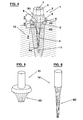
- Fig. 1
- shows schematically an embodiment of a core member according to the invention,
- Fig. 2
- shows a post according to the invention,
- Fig. 3
- shows the post of
Fig. 2 inserted in core member ofFig. 1 , - Fig. 4
- shows the assembly of
Fig. 3 fixed within the root canal of a tooth, - Fig. 5
- shows schematically a drill according to the invention, and
- Fig. 6
- shows schematically a reamer according to the invention.
- The
core member 1 ofFig. 1 comprises - see alsoFig. 4 - ananchorage surface 2, acrown surface 3 and a throughbore 4. Thecrown surface 3 comprises aconical part 4 for receiving a crown or the like, followed by atransfer part 5 with a hyperbolic form ending in aring face 6 having the greatest diameter of the core member. Theanchorage surface 2 has also a hyperbolic form. - Both hyperboloids are hyperboloids of revolution of one sheet. These hyperboloids of revolution are defined as

whereby a = b. The opening of the hyperbola, resp. the angle α of the asymptote is defined as
- For the present case of a core member, where a = b these values can be calculated on the basis of the parameters given below.
- In architecture, hyperboloids are known since the 19th century and in modern time some chimneys of nuclear power plants have also the shape of a hyperboloid.
- As follows from
Fig. 4 , the hyperbolicshaped anchorage surface 2 has the advantage to require a minimal removal of the wall of the root canal, causing its minimal weakening. - The hyperbolic shape of
surface 3 allows a better transmittal of the forces bearing on the crown to the core member. - It is understood that the values of a = b, and c for
crown surface 2 are not necessarily the same as foranchorage surface 3. - As examples the following values for the greatest diameter R5 of
ring face 6 and the smallest diameter R1 of thecrown surface 2 and R2 ofanchorage surface 3 are as follows:


- The distance D1 between the beginning of the
transfer part 5 and thering face 6 can be 1.5 - 3 mm, and D2 between thering face 6 and the end of the core member can be 1.5 - 3. mm. - The
post 7 comprises acylindrical part 8 to be received inbore 4 of the core member, followed by ananchorage part 9, which surface can also have a hyperbolic shape with the following values, where a = b:

- The distance D3 between R3 and R4 is 8 - 12 mm.
- The hyperbolic surfaces of the crown and anchoring part and of the post allow the optimal distribution of pressure or stress and prevents post, core member or root fractures.
- In
Fig. 4 the assembled core member and post is shown cemented into theroot canal 11 oftooth 12. - The whole assembly comprises a calibrated drill or reamer 13 with reaming or drilling
part 2D having the same shape as thecore member part 2 for giving the root canal the hyperbolic shape which corresponds to the shape of the anchorage part of the core member and a calibrated drill or reamer 14 which drilling or reamingpart 9D corresponds to theanchorage part 9 of the post. - The assembly of the invention allows for multiple ways of application:
- 1) The post can be fixed and cemented into the core member prior to insertion in the root canal, thereby it is possible to adjust it's length, resp. to have the same length as the core member in the crown part.
- 2) The post can be inserted first within the root canal and the core member is then sledded down the post till it reaches it's prepared seat in the upper part of the root canal.
- 3) The core member can be cemented first in the root canal and the post can be sledded through
bore 4 into the root canal and thecylindrical part 8 of the post is - after adjusting its length - cemented withinbore 4. - 4) In some cases, the post can be used alone, without using the core member in teeth having particular roots or multi roots.
- Although it is possible to produce the core member and the post of metal, usually stainless steel, as known in the prior art, it is preferable to produce the said parts of glass fibre reinforced composite material, for example as disclosed in
US-A-6 402 519 to the same applicant.
Claims (8)
- Tooth root channel anchorage assembly, comprising a core member (1) to be fixed within the tooth root channel (11) and a post (7) to be inserted into the core member, the core member having a thoroughgoing bore (4), characterised in that the core member comprises a crown part (3) and an anchorage part (2) to be fixed within the root canal, the surface of the anchorage part (2) having a substantially hyperbolic form.
- Assembly according to claim 1, characterised in that the crown part (3) of the core member (1) comprises a surface (5) which has a substantially hyperbolic form.
- Assembly according to claim 1 or 2, characterised in that the post (7) has a cylindrical part (8) fitting slidably into the bore (4) of the core member (1), which cylindrical part is followed by a post anchorage part, which surface (9) has a hyperbolic form.
- Assembly according to any of claims 1 to 3, characterised in that the core member and the post are made of fibre glass reinforced composite material.
- Assembly according to any of claims 1 to 4, characterised in that the hyperboloid is a hyperboloid of revolution of one sheet, according to the formula:


- Assembly according to any of claims 1 to 5, wherein the core member has the following values:
a = b
the greatest diameter R5 of the core member = 3 - 5 mm, the smallest diameter R1 of the crown surface = 2 - 4 mm, the smallest diameter R2 of the anchorage surface = 1.5 - 3 mm, the distance D1 between the beginning of the hyperbolic surface 5 and the greatest diameter R5 = 1.5 - 3 mm, and the distance D2 between the greatest diameter R5 and the end of the anchorage part R2 = 1.5 - 3 mm. - Assembly according to any of claims 1 to 6, wherein the post has the following values:
a = b
the diameter R3 of the cylindrical part 8 = 1.3 - 1.7 mm, the diameter R4 of the end of the post = 0.3 - 0.7 mm, the distance D3 between R3 and R4 = 8 - 12 mm. - Assembly according to any of claims 1 to 7, characterised in that it further comprises a drill or reamer (13) having the same drilling or reaming surface (D2) as the anchorage part (2) of the core member (1) and a drill or reamer (14) having the same drilling or reaming surface (D9) as the post part (9) to be inserted into the root canal.
Priority Applications (7)
| Application Number | Priority Date | Filing Date | Title |
|---|---|---|---|
| ES06405494T ES2332736T3 (en) | 2006-11-27 | 2006-11-27 | ANCHORAGE SET OF THE ROOT CHANNEL OF A MUELA. |
| AT06405494T ATE448750T1 (en) | 2006-11-27 | 2006-11-27 | DENTAL ROOT CANAL ANCHORING ARRANGEMENT |
| EP06405494A EP1925269B1 (en) | 2006-11-27 | 2006-11-27 | Tooth root canal anchorage assembly |
| DE602006010577T DE602006010577D1 (en) | 2006-11-27 | 2006-11-27 | Tooth root canal anchor assembly |
| US11/942,745 US8398403B2 (en) | 2006-11-27 | 2007-11-20 | Tooth root canal anchorage assembly |
| JP2007303861A JP5405013B2 (en) | 2006-11-27 | 2007-11-26 | Root canal anchor assembly |
| BRPI0704210-8A BRPI0704210A (en) | 2006-11-27 | 2007-11-27 | tooth root canal anchor assembly |
Applications Claiming Priority (1)
| Application Number | Priority Date | Filing Date | Title |
|---|---|---|---|
| EP06405494A EP1925269B1 (en) | 2006-11-27 | 2006-11-27 | Tooth root canal anchorage assembly |
Publications (2)
| Publication Number | Publication Date |
|---|---|
| EP1925269A1 true EP1925269A1 (en) | 2008-05-28 |
| EP1925269B1 EP1925269B1 (en) | 2009-11-18 |
Family
ID=37998377
Family Applications (1)
| Application Number | Title | Priority Date | Filing Date |
|---|---|---|---|
| EP06405494A Active EP1925269B1 (en) | 2006-11-27 | 2006-11-27 | Tooth root canal anchorage assembly |
Country Status (7)
| Country | Link |
|---|---|
| US (1) | US8398403B2 (en) |
| EP (1) | EP1925269B1 (en) |
| JP (1) | JP5405013B2 (en) |
| AT (1) | ATE448750T1 (en) |
| BR (1) | BRPI0704210A (en) |
| DE (1) | DE602006010577D1 (en) |
| ES (1) | ES2332736T3 (en) |
Cited By (3)
| Publication number | Priority date | Publication date | Assignee | Title |
|---|---|---|---|---|
| WO2018166879A1 (en) * | 2017-03-14 | 2018-09-20 | Stephan Lampl | Endodontic pin |
| CN111821044A (en) * | 2020-04-07 | 2020-10-27 | 南京医科大学附属口腔医院 | Integrative hat of bolt formula stake core suitable for back tooth gum repair space is less than 3mm |
| WO2022036424A1 (en) | 2020-08-21 | 2022-02-24 | Angelus Industria De Produtos Odontologicos S/A | System for insertion into the root canal, method for obtaining a fastening element using said system and fastening element |
Families Citing this family (4)
| Publication number | Priority date | Publication date | Assignee | Title |
|---|---|---|---|---|
| JP2008506485A (en) * | 2004-07-19 | 2008-03-06 | ハーラス、ベンジャミン レオポルド | Superstructure for dental crown superstructure system |
| PL2522300T3 (en) | 2011-05-10 | 2021-06-28 | Peter Nordin | Abutment for a dental implant |
| PT2522299T (en) * | 2011-05-10 | 2020-10-20 | Harald E Nordin | Dental implant |
| US20180055614A1 (en) * | 2016-09-01 | 2018-03-01 | National Guard Health Affairs | Flared conical dental post |
Citations (12)
| Publication number | Priority date | Publication date | Assignee | Title |
|---|---|---|---|---|
| EP0037864A1 (en) * | 1980-04-09 | 1981-10-21 | Edward S. Scott | Dental post and method of installing |
| EP0083028A1 (en) * | 1981-12-16 | 1983-07-06 | Fraunhofer-Gesellschaft Zur Förderung Der Angewandten Forschung E.V. | Joining element for an implant and a superstructure |
| EP0113792A1 (en) | 1983-01-17 | 1984-07-25 | Gebr. Brasseler GmbH & Co. KG | Atraumatic endodontic reconstruction system |
| CH652910A5 (en) * | 1981-03-04 | 1985-12-13 | Herbert Dr Med Dent Spang | Cylindrical metal pin for anchoring a dental reconstruction in the root canal of a human tooth |
| EP0245878A2 (en) | 1983-01-17 | 1987-11-19 | Gebr. Brasseler GmbH & Co. KG | Atraumatic endodontic reconstruction system and process |
| WO1992016157A1 (en) * | 1991-03-19 | 1992-10-01 | Lars Hansson | A root channel pin |
| FR2716795A1 (en) * | 1994-03-02 | 1995-09-08 | Millet Laurent | Dental drill or grinding bit for forming crown-receiving stump |
| WO1996025119A1 (en) * | 1995-02-17 | 1996-08-22 | Marc Reynaud | Self-locking dental post |
| WO1996029017A1 (en) * | 1995-03-23 | 1996-09-26 | Institut Straumann Ag | Fatigue-proof geometry of parapulpar or endodontic securing components |
| EP0780100A2 (en) * | 1995-12-20 | 1997-06-25 | Maillefer Instruments S.A. | Instrument for the preparation of dental root canals |
| US6402519B1 (en) | 1999-08-27 | 2002-06-11 | Harald Nordin Sa | Anchorage elements and auxiliary instruments for dentistry |
| US20040265783A1 (en) * | 1999-05-12 | 2004-12-30 | Ajit Karmaker | Endodontic post and obturating system |
Family Cites Families (25)
| Publication number | Priority date | Publication date | Assignee | Title |
|---|---|---|---|---|
| US352785A (en) * | 1886-11-16 | Lugius t | ||
| US238334A (en) * | 1881-03-01 | Artificial tooth-crown | ||
| US616302A (en) * | 1898-12-20 | George evans | ||
| US4400160A (en) * | 1981-11-06 | 1983-08-23 | Leopold Paul Lustig | Atraumatic endodontic reconstruction system and process |
| US4505679A (en) * | 1983-06-27 | 1985-03-19 | Gutentag Herbert N | Endodontic sealing apparatus and method |
| US4604060A (en) * | 1985-05-14 | 1986-08-05 | Ipco Corporation | Dental post system |
| US5052930A (en) * | 1989-11-22 | 1991-10-01 | Lodde Jean Pierre | Dental implant and method of implantation |
| US5518399A (en) * | 1993-09-27 | 1996-05-21 | Tru-Flex Post Systems, Inc. | Method of restoring an endodonticall y-treated tooth |
| US6206695B1 (en) * | 1994-02-14 | 2001-03-27 | Nelson J. Wong | Step-back eliminating tapered dental cutting instruments for improved root canal treatment and method |
| US5595486A (en) * | 1995-04-14 | 1997-01-21 | Manocha; Ashok | Method and device for filling an endodontically prepared tooth |
| CH691789A5 (en) * | 1995-12-20 | 2001-10-31 | Maillefer Instr Sa | Instrument set for the boring of radicular dental canals. |
| JP3782499B2 (en) * | 1996-01-25 | 2006-06-07 | ワイスマン バーナード | Dental post with support frame |
| US5779476A (en) * | 1997-04-30 | 1998-07-14 | Roetzer; Patrick | Rapid adapting precision transformer for occlusal resins |
| JP4413281B2 (en) * | 1998-03-10 | 2010-02-10 | サンメディカル株式会社 | Dental abutment, reinforcing core for constructing dental abutment and kit for constructing dental abutment |
| US6135775A (en) * | 1999-08-03 | 2000-10-24 | Weisman; Bernard | Longitudinally centrally convergant dental post |
| US20030031981A1 (en) * | 2000-10-21 | 2003-02-13 | Robert Holt | Prosthetic implant |
| US7303817B2 (en) * | 2001-10-24 | 2007-12-04 | Weitao Jia | Dental filling material |
| US20030235805A1 (en) * | 2002-05-21 | 2003-12-25 | Steven Lax | Dental post with countersink |
| DE20209170U1 (en) * | 2002-06-12 | 2004-02-19 | Dinkelacker, Wolfgang, Dr.med.dent. | bone implant |
| US7341453B2 (en) * | 2002-11-01 | 2008-03-11 | Coatoam Gary W | Dental implant method and apparatus |
| US7731498B2 (en) * | 2003-05-16 | 2010-06-08 | Mcspadden John T | Endododontic file with multi-tapered flutes |
| JP2008506485A (en) | 2004-07-19 | 2008-03-06 | ハーラス、ベンジャミン レオポルド | Superstructure for dental crown superstructure system |
| FR2886837B1 (en) * | 2005-06-14 | 2008-04-11 | Micro Mega Int Mfg Sa | DRAFT FOR THE MANUFACTURE OF AN ENDODONTIC INSTRUMENT AND METHOD FOR MANUFACTURING THE SAME |
| FR2892618B1 (en) * | 2005-10-28 | 2008-01-25 | De La Garanderie Emmanue Payen | DEVICE FOR PREPARING AND SHUTTING THE ENDODONTIC CAVITY OF A TOOTH |
| US7270541B1 (en) * | 2006-03-02 | 2007-09-18 | Johnson William B | Endodontic files having variable helical angle flutes |
-
2006
- 2006-11-27 EP EP06405494A patent/EP1925269B1/en active Active
- 2006-11-27 AT AT06405494T patent/ATE448750T1/en not_active IP Right Cessation
- 2006-11-27 DE DE602006010577T patent/DE602006010577D1/en active Active
- 2006-11-27 ES ES06405494T patent/ES2332736T3/en active Active
-
2007
- 2007-11-20 US US11/942,745 patent/US8398403B2/en active Active
- 2007-11-26 JP JP2007303861A patent/JP5405013B2/en active Active
- 2007-11-27 BR BRPI0704210-8A patent/BRPI0704210A/en not_active Application Discontinuation
Patent Citations (12)
| Publication number | Priority date | Publication date | Assignee | Title |
|---|---|---|---|---|
| EP0037864A1 (en) * | 1980-04-09 | 1981-10-21 | Edward S. Scott | Dental post and method of installing |
| CH652910A5 (en) * | 1981-03-04 | 1985-12-13 | Herbert Dr Med Dent Spang | Cylindrical metal pin for anchoring a dental reconstruction in the root canal of a human tooth |
| EP0083028A1 (en) * | 1981-12-16 | 1983-07-06 | Fraunhofer-Gesellschaft Zur Förderung Der Angewandten Forschung E.V. | Joining element for an implant and a superstructure |
| EP0113792A1 (en) | 1983-01-17 | 1984-07-25 | Gebr. Brasseler GmbH & Co. KG | Atraumatic endodontic reconstruction system |
| EP0245878A2 (en) | 1983-01-17 | 1987-11-19 | Gebr. Brasseler GmbH & Co. KG | Atraumatic endodontic reconstruction system and process |
| WO1992016157A1 (en) * | 1991-03-19 | 1992-10-01 | Lars Hansson | A root channel pin |
| FR2716795A1 (en) * | 1994-03-02 | 1995-09-08 | Millet Laurent | Dental drill or grinding bit for forming crown-receiving stump |
| WO1996025119A1 (en) * | 1995-02-17 | 1996-08-22 | Marc Reynaud | Self-locking dental post |
| WO1996029017A1 (en) * | 1995-03-23 | 1996-09-26 | Institut Straumann Ag | Fatigue-proof geometry of parapulpar or endodontic securing components |
| EP0780100A2 (en) * | 1995-12-20 | 1997-06-25 | Maillefer Instruments S.A. | Instrument for the preparation of dental root canals |
| US20040265783A1 (en) * | 1999-05-12 | 2004-12-30 | Ajit Karmaker | Endodontic post and obturating system |
| US6402519B1 (en) | 1999-08-27 | 2002-06-11 | Harald Nordin Sa | Anchorage elements and auxiliary instruments for dentistry |
Cited By (6)
| Publication number | Priority date | Publication date | Assignee | Title |
|---|---|---|---|---|
| WO2018166879A1 (en) * | 2017-03-14 | 2018-09-20 | Stephan Lampl | Endodontic pin |
| AU2018233675B2 (en) * | 2017-03-14 | 2023-12-14 | Edelweiss Dentistry Products Gmbh | Endodontic pin |
| CN111821044A (en) * | 2020-04-07 | 2020-10-27 | 南京医科大学附属口腔医院 | Integrative hat of bolt formula stake core suitable for back tooth gum repair space is less than 3mm |
| CN111821044B (en) * | 2020-04-07 | 2021-02-05 | 南京医科大学附属口腔医院 | Integrative hat of bolt formula stake core suitable for back tooth gum repair space is less than 3mm |
| WO2022036424A1 (en) | 2020-08-21 | 2022-02-24 | Angelus Industria De Produtos Odontologicos S/A | System for insertion into the root canal, method for obtaining a fastening element using said system and fastening element |
| US11864968B2 (en) | 2020-08-21 | 2024-01-09 | Angelus Industria De Produtos Odontologicos S/A | System for insertion into the root canal, method for obtaining a fastening element using said system and fastening element |
Also Published As
| Publication number | Publication date |
|---|---|
| ES2332736T3 (en) | 2010-02-11 |
| JP5405013B2 (en) | 2014-02-05 |
| EP1925269B1 (en) | 2009-11-18 |
| JP2008132334A (en) | 2008-06-12 |
| BRPI0704210A (en) | 2008-07-22 |
| US20080124682A1 (en) | 2008-05-29 |
| US8398403B2 (en) | 2013-03-19 |
| ATE448750T1 (en) | 2009-12-15 |
| DE602006010577D1 (en) | 2009-12-31 |
Similar Documents
| Publication | Publication Date | Title |
|---|---|---|
| EP1925269B1 (en) | Tooth root canal anchorage assembly | |
| EP0484947B1 (en) | Active/passive dental posts | |
| EP0814724B1 (en) | Device for connecting a dental implant to a conical secondary element | |
| US5489210A (en) | Expanding dental implant and method for its use | |
| US4846685A (en) | Perforated dental post system | |
| EP1210028B1 (en) | Longitudinally centrally convergent dental post | |
| CN102307540B (en) | A dental implant, a dental implant kit and a method of securing a dental bridge to the jaw of a patient | |
| RU2402992C2 (en) | Dental implant system and method for implantation and making implant system | |
| WO1992003103A2 (en) | Method and apparatus for installing a post in a tooth having an existing endodontic obturator therein | |
| US5284443A (en) | Method of forming dental restorations | |
| US20080280254A1 (en) | Molar Implant and Method | |
| JPH0376939B2 (en) | ||
| WO2002053057A1 (en) | Device for forming holes and inserting sleeves in a unit incorporated in a dental attachment part | |
| EP3166530B1 (en) | Dental prostheses cemented onto implants and/or abutments having a reverse margin | |
| EP2008612A1 (en) | Improved dental implant | |
| US20100167242A1 (en) | Dental implant | |
| US5051092A (en) | Dental anchor and a drill for use therewith | |
| US5788497A (en) | Dental post | |
| US5944529A (en) | Two-component dental post system | |
| EP0788781B1 (en) | Abutment screw | |
| EP3506852B1 (en) | Dental implant cover | |
| DE19718176C2 (en) | Cone-shaped implant | |
| AU2002217691B2 (en) | Device for forming holes and inserting sleeves in a unit incorporated in a dental attachment part | |
| AU2002217691A1 (en) | Device for forming holes and inserting sleeves in a unit incorporated in a dental attachment part | |
| ITFO20010018A1 (en) | PROCEDURE AND MEANS FOR IMPLANTING DENTAL PINS IN NATURAL DENTAL ROOTS. |
Legal Events
| Date | Code | Title | Description |
|---|---|---|---|
| PUAI | Public reference made under article 153(3) epc to a published international application that has entered the european phase |
Free format text: ORIGINAL CODE: 0009012 |
|
| AK | Designated contracting states |
Kind code of ref document: A1 Designated state(s): AT BE BG CH CY CZ DE DK EE ES FI FR GB GR HU IE IS IT LI LT LU LV MC NL PL PT RO SE SI SK TR |
|
| AX | Request for extension of the european patent |
Extension state: AL BA HR MK RS |
|
| 17P | Request for examination filed |
Effective date: 20081007 |
|
| 17Q | First examination report despatched |
Effective date: 20081121 |
|
| AKX | Designation fees paid |
Designated state(s): AT BE BG CH CY CZ DE DK EE ES FI FR GB GR HU IE IS IT LI LT LU LV MC NL PL PT RO SE SI SK TR |
|
| GRAP | Despatch of communication of intention to grant a patent |
Free format text: ORIGINAL CODE: EPIDOSNIGR1 |
|
| GRAS | Grant fee paid |
Free format text: ORIGINAL CODE: EPIDOSNIGR3 |
|
| GRAA | (expected) grant |
Free format text: ORIGINAL CODE: 0009210 |
|
| AK | Designated contracting states |
Kind code of ref document: B1 Designated state(s): AT BE BG CH CY CZ DE DK EE ES FI FR GB GR HU IE IS IT LI LT LU LV MC NL PL PT RO SE SI SK TR |
|
| REG | Reference to a national code |
Ref country code: GB Ref legal event code: FG4D |
|
| REG | Reference to a national code |
Ref country code: CH Ref legal event code: EP Ref country code: CH Ref legal event code: NV Representative=s name: AMMANN PATENTANWAELTE AG BERN |
|
| REG | Reference to a national code |
Ref country code: IE Ref legal event code: FG4D |
|
| REF | Corresponds to: |
Ref document number: 602006010577 Country of ref document: DE Date of ref document: 20091231 Kind code of ref document: P |
|
| REG | Reference to a national code |
Ref country code: ES Ref legal event code: FG2A Ref document number: 2332736 Country of ref document: ES Kind code of ref document: T3 |
|
| REG | Reference to a national code |
Ref country code: SE Ref legal event code: TRGR |
|
| LTIE | Lt: invalidation of european patent or patent extension |
Effective date: 20091118 |
|
| PG25 | Lapsed in a contracting state [announced via postgrant information from national office to epo] |
Ref country code: PT Free format text: LAPSE BECAUSE OF FAILURE TO SUBMIT A TRANSLATION OF THE DESCRIPTION OR TO PAY THE FEE WITHIN THE PRESCRIBED TIME-LIMIT Effective date: 20100318 Ref country code: LT Free format text: LAPSE BECAUSE OF FAILURE TO SUBMIT A TRANSLATION OF THE DESCRIPTION OR TO PAY THE FEE WITHIN THE PRESCRIBED TIME-LIMIT Effective date: 20091118 Ref country code: FI Free format text: LAPSE BECAUSE OF FAILURE TO SUBMIT A TRANSLATION OF THE DESCRIPTION OR TO PAY THE FEE WITHIN THE PRESCRIBED TIME-LIMIT Effective date: 20091118 Ref country code: IS Free format text: LAPSE BECAUSE OF FAILURE TO SUBMIT A TRANSLATION OF THE DESCRIPTION OR TO PAY THE FEE WITHIN THE PRESCRIBED TIME-LIMIT Effective date: 20100318 |
|
| PG25 | Lapsed in a contracting state [announced via postgrant information from national office to epo] |
Ref country code: PL Free format text: LAPSE BECAUSE OF FAILURE TO SUBMIT A TRANSLATION OF THE DESCRIPTION OR TO PAY THE FEE WITHIN THE PRESCRIBED TIME-LIMIT Effective date: 20091118 Ref country code: LV Free format text: LAPSE BECAUSE OF FAILURE TO SUBMIT A TRANSLATION OF THE DESCRIPTION OR TO PAY THE FEE WITHIN THE PRESCRIBED TIME-LIMIT Effective date: 20091118 Ref country code: CY Free format text: LAPSE BECAUSE OF FAILURE TO SUBMIT A TRANSLATION OF THE DESCRIPTION OR TO PAY THE FEE WITHIN THE PRESCRIBED TIME-LIMIT Effective date: 20091118 Ref country code: SI Free format text: LAPSE BECAUSE OF FAILURE TO SUBMIT A TRANSLATION OF THE DESCRIPTION OR TO PAY THE FEE WITHIN THE PRESCRIBED TIME-LIMIT Effective date: 20091118 |
|
| PG25 | Lapsed in a contracting state [announced via postgrant information from national office to epo] |
Ref country code: MC Free format text: LAPSE BECAUSE OF NON-PAYMENT OF DUE FEES Effective date: 20091130 Ref country code: BE Free format text: LAPSE BECAUSE OF FAILURE TO SUBMIT A TRANSLATION OF THE DESCRIPTION OR TO PAY THE FEE WITHIN THE PRESCRIBED TIME-LIMIT Effective date: 20091118 Ref country code: AT Free format text: LAPSE BECAUSE OF FAILURE TO SUBMIT A TRANSLATION OF THE DESCRIPTION OR TO PAY THE FEE WITHIN THE PRESCRIBED TIME-LIMIT Effective date: 20091118 |
|
| PG25 | Lapsed in a contracting state [announced via postgrant information from national office to epo] |
Ref country code: EE Free format text: LAPSE BECAUSE OF FAILURE TO SUBMIT A TRANSLATION OF THE DESCRIPTION OR TO PAY THE FEE WITHIN THE PRESCRIBED TIME-LIMIT Effective date: 20091118 Ref country code: RO Free format text: LAPSE BECAUSE OF FAILURE TO SUBMIT A TRANSLATION OF THE DESCRIPTION OR TO PAY THE FEE WITHIN THE PRESCRIBED TIME-LIMIT Effective date: 20091118 Ref country code: BG Free format text: LAPSE BECAUSE OF FAILURE TO SUBMIT A TRANSLATION OF THE DESCRIPTION OR TO PAY THE FEE WITHIN THE PRESCRIBED TIME-LIMIT Effective date: 20100218 Ref country code: DK Free format text: LAPSE BECAUSE OF FAILURE TO SUBMIT A TRANSLATION OF THE DESCRIPTION OR TO PAY THE FEE WITHIN THE PRESCRIBED TIME-LIMIT Effective date: 20091118 |
|
| PG25 | Lapsed in a contracting state [announced via postgrant information from national office to epo] |
Ref country code: CZ Free format text: LAPSE BECAUSE OF FAILURE TO SUBMIT A TRANSLATION OF THE DESCRIPTION OR TO PAY THE FEE WITHIN THE PRESCRIBED TIME-LIMIT Effective date: 20091118 Ref country code: SK Free format text: LAPSE BECAUSE OF FAILURE TO SUBMIT A TRANSLATION OF THE DESCRIPTION OR TO PAY THE FEE WITHIN THE PRESCRIBED TIME-LIMIT Effective date: 20091118 |
|
| PLBE | No opposition filed within time limit |
Free format text: ORIGINAL CODE: 0009261 |
|
| STAA | Information on the status of an ep patent application or granted ep patent |
Free format text: STATUS: NO OPPOSITION FILED WITHIN TIME LIMIT |
|
| 26N | No opposition filed |
Effective date: 20100819 |
|
| PG25 | Lapsed in a contracting state [announced via postgrant information from national office to epo] |
Ref country code: GR Free format text: LAPSE BECAUSE OF FAILURE TO SUBMIT A TRANSLATION OF THE DESCRIPTION OR TO PAY THE FEE WITHIN THE PRESCRIBED TIME-LIMIT Effective date: 20100219 Ref country code: IE Free format text: LAPSE BECAUSE OF NON-PAYMENT OF DUE FEES Effective date: 20091127 |
|
| PG25 | Lapsed in a contracting state [announced via postgrant information from national office to epo] |
Ref country code: LU Free format text: LAPSE BECAUSE OF NON-PAYMENT OF DUE FEES Effective date: 20091127 |
|
| PG25 | Lapsed in a contracting state [announced via postgrant information from national office to epo] |
Ref country code: HU Free format text: LAPSE BECAUSE OF FAILURE TO SUBMIT A TRANSLATION OF THE DESCRIPTION OR TO PAY THE FEE WITHIN THE PRESCRIBED TIME-LIMIT Effective date: 20100519 |
|
| PG25 | Lapsed in a contracting state [announced via postgrant information from national office to epo] |
Ref country code: TR Free format text: LAPSE BECAUSE OF FAILURE TO SUBMIT A TRANSLATION OF THE DESCRIPTION OR TO PAY THE FEE WITHIN THE PRESCRIBED TIME-LIMIT Effective date: 20091118 |
|
| REG | Reference to a national code |
Ref country code: FR Ref legal event code: PLFP Year of fee payment: 10 |
|
| REG | Reference to a national code |
Ref country code: FR Ref legal event code: PLFP Year of fee payment: 11 |
|
| REG | Reference to a national code |
Ref country code: FR Ref legal event code: PLFP Year of fee payment: 12 |
|
| PGFP | Annual fee paid to national office [announced via postgrant information from national office to epo] |
Ref country code: ES Payment date: 20230125 Year of fee payment: 17 |
|
| P01 | Opt-out of the competence of the unified patent court (upc) registered |
Effective date: 20230526 |
|
| PGFP | Annual fee paid to national office [announced via postgrant information from national office to epo] |
Ref country code: NL Payment date: 20231120 Year of fee payment: 18 |
|
| PGFP | Annual fee paid to national office [announced via postgrant information from national office to epo] |
Ref country code: GB Payment date: 20231123 Year of fee payment: 18 |
|
| PGFP | Annual fee paid to national office [announced via postgrant information from national office to epo] |
Ref country code: SE Payment date: 20231120 Year of fee payment: 18 Ref country code: IT Payment date: 20231124 Year of fee payment: 18 Ref country code: FR Payment date: 20231120 Year of fee payment: 18 Ref country code: DE Payment date: 20231121 Year of fee payment: 18 Ref country code: CH Payment date: 20231201 Year of fee payment: 18 |