EP1924730B1 - Motor and controller assembly for a horizontal axis washing machine - Google Patents
Motor and controller assembly for a horizontal axis washing machine Download PDFInfo
- Publication number
- EP1924730B1 EP1924730B1 EP06813646A EP06813646A EP1924730B1 EP 1924730 B1 EP1924730 B1 EP 1924730B1 EP 06813646 A EP06813646 A EP 06813646A EP 06813646 A EP06813646 A EP 06813646A EP 1924730 B1 EP1924730 B1 EP 1924730B1
- Authority
- EP
- European Patent Office
- Prior art keywords
- controller
- assembly
- electric motor
- heat sink
- motor
- Prior art date
- Legal status (The legal status is an assumption and is not a legal conclusion. Google has not performed a legal analysis and makes no representation as to the accuracy of the status listed.)
- Revoked
Links
Images


Classifications
-
- D—TEXTILES; PAPER
- D06—TREATMENT OF TEXTILES OR THE LIKE; LAUNDERING; FLEXIBLE MATERIALS NOT OTHERWISE PROVIDED FOR
- D06F—LAUNDERING, DRYING, IRONING, PRESSING OR FOLDING TEXTILE ARTICLES
- D06F37/00—Details specific to washing machines covered by groups D06F21/00 - D06F25/00
- D06F37/20—Mountings, e.g. resilient mountings, for the rotary receptacle, motor, tub or casing; Preventing or damping vibrations
- D06F37/206—Mounting of motor
-
- D—TEXTILES; PAPER
- D06—TREATMENT OF TEXTILES OR THE LIKE; LAUNDERING; FLEXIBLE MATERIALS NOT OTHERWISE PROVIDED FOR
- D06F—LAUNDERING, DRYING, IRONING, PRESSING OR FOLDING TEXTILE ARTICLES
- D06F37/00—Details specific to washing machines covered by groups D06F21/00 - D06F25/00
- D06F37/30—Driving arrangements
- D06F37/304—Arrangements or adaptations of electric motors
-
- H—ELECTRICITY
- H02—GENERATION; CONVERSION OR DISTRIBUTION OF ELECTRIC POWER
- H02K—DYNAMO-ELECTRIC MACHINES
- H02K11/00—Structural association of dynamo-electric machines with electric components or with devices for shielding, monitoring or protection
- H02K11/30—Structural association with control circuits or drive circuits
- H02K11/33—Drive circuits, e.g. power electronics
-
- Y—GENERAL TAGGING OF NEW TECHNOLOGICAL DEVELOPMENTS; GENERAL TAGGING OF CROSS-SECTIONAL TECHNOLOGIES SPANNING OVER SEVERAL SECTIONS OF THE IPC; TECHNICAL SUBJECTS COVERED BY FORMER USPC CROSS-REFERENCE ART COLLECTIONS [XRACs] AND DIGESTS
- Y02—TECHNOLOGIES OR APPLICATIONS FOR MITIGATION OR ADAPTATION AGAINST CLIMATE CHANGE
- Y02B—CLIMATE CHANGE MITIGATION TECHNOLOGIES RELATED TO BUILDINGS, e.g. HOUSING, HOUSE APPLIANCES OR RELATED END-USER APPLICATIONS
- Y02B40/00—Technologies aiming at improving the efficiency of home appliances, e.g. induction cooking or efficient technologies for refrigerators, freezers or dish washers
Definitions
- the present invention relates to an electric motor and controller assembly for a horizontal axis washing machine.
- a controller for the electric motor is mounted away from the electric motor, often adjacent to a controller for the washing machine, and electrically coupled to the electric motor via a cable assembly.
- these known washing machines have several disadvantages. For example, locating the motor controller away from the motor requires use of the cable assembly, which typically includes interference retarding components to reduce television interference. Additionally, because the motor controllers commonly include heat sinks mounted within a controller housing - also referred to as a drip shield - the controller housing is unnecessarily large, resulting in increased materials cost, and restricts heat dissipation from the heat sink.
- the present inventors have succeeded at designing, among other things, an integrated motor and controller assembly for horizontal axis washing machines.
- an electric motor and controller assembly for a horizontal axis washing machine is provided acc. to the appended claims.
- US 4668898 A discloses an electric motor and controller assembly for a horizontal axis washing machine acc. to the preamble of claim 1.
- FIG. 1 is a perspective view of an electric motor and controller assembly according to one exemplary embodiment of the present invention.
- FIG. 2 is a block diagram of a horizontal axis washing machine according to another exemplary embodiment.
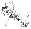
- FIG. 3 is an exploded perspective view of the electric motor and controller assembly of FIG. 1 .
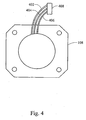
- FIG. 4 is a top plan view of the stator of FIG. 3 illustrating a direct connection of magnet wires to a connector for the motor controller.
- FIG. 1 An exemplary motor and controller assembly for a horizontal axis washing machine according to one embodiment of the present invention is illustrated in Fig. 1 and indicated generally by reference number 100.
- the assembly 100 includes an electric motor 102 and a controller 104.
- the controller 104 includes, among other things, software for controlling operation of the electric motor 102 in a horizontal axis washing machine, typically in response to commands from a controller for the washing machine.
- the electric motor 102 includes at least one attachment point 106 for mounting the electric motor 102 in a horizontal axis washing machine.
- An additional attachment point 107 is shown in Fig. 3 , described below.
- the electric motor 102 is a variable speed controlled induction motor. It should be understood, however, that other motor types, including brushless permanent magnet (BPM) and switched reluctance (SR) motors, can be employed without departing from the scope of the present invention. Furthermore, while the embodiment of Fig. 1 contemplates distinct machine and motor controllers, the machine controller can be integrated into the motor controller mounted to the electric motor without departing from the scope of the present invention.
- BPM brushless permanent magnet
- SR switched reluctance
- the controller 104 of Fig. 1 is mounted to the electric motor 102.
- various components employed in known designs are preferably eliminated in many embodiments of the invention, including wiring harnesses commonly provided between motors and controllers, EMI retarding components commonly included in the wiring harnesses, connectors, etc. Mounting the controller on the motor contributes to a more compact design, simplifies manufacturing, and reduces production costs for the assembly 100 and any horizontal axis washing machine that incorporates the assembly 100.
- Fig. 2 illustrates a horizontal axis washing machine 200 according to another embodiment.
- the washing machine 200 includes an outer tub 202, an inner tub 204, an electric motor 208 and a controller 210 for the electric motor 208.
- the controller 210 is mounted to the electric motor 208. Further, at least a portion of the controller 210 is positioned under the outer tub 202.
- the outer tub 202 provides drip protection for the controller including, for example, when the inner tub 204 overflows with water.
- the controller includes a housing (also referred to as a drip shield) for providing drip protection, the dimensions of the housing can be reduced, resulting in material savings, due to the drip protection provided by the tub 204.
- a housing also referred to as a drip shield
- positioning the motor 208 and the controller 210 under the outer tub 202 can help move air across any heat sink positioned on the motor 208 or the controller 210, particularly where the outer tub 202 is suspended within the washing machine 200 for limited movement or vibration of the outer tub 202 during operation of the machine 200.
- the motor 208 is coupled to the inner tub 204 via a belt 206 for driving rotation of the inner tub 204.
- Fig. 2 also illustrates the generally horizontal center axis 212 of the inner tub 204.
- FIG. 1 One example of a suitable motor and controller assembly for use in the horizontal axis washing machine 200 of Fig. 2 is the motor and controller assembly 100 shown in Fig. 1 .
- the assembly 100 will now be further described with reference to the exploded view of Fig. 3 .
- the electric motor 102 of Fig. 1 includes a stator 108, a rotor 110 situated for rotation relative to the stator, a shaft 112 and endshields 114, 116.
- the rotor 110 is designed to rotate within an inner bore of the stator. 108.
- the controller 104 shown in FIG. 1 is mounted to the endshield 114 and includes a circuit board 118, a housing 120, and various circuit components 122 (including at least one heat producing component 122a) attached to the circuit board 118 and generally protected by the housing 120.
- the housing 120 includes a base 120a that is attached to the endshield 114; and a cover 120b that can be removably attached to the base 120a.
- a heat sink 109 positioned on the endshield 114.
- the heat sink is integrally attached to the endshieid.
- the heat sink 109 and the endshield 114 have a monolithic (i.e., single unit) construction and are formed from cast grade aluminum. This results in material savings as compared to prior art designs employing separate endshields and heat sinks.
- the heat sink 109 and the endshield 114 can be formed separately, in which case the heat sink 109 can optionally be positioned at a different location on the assembly 100.
- the heat sink 109 is provided for dissipating heat generated by the heat producing component 122a (and possibly other components 122).
- the heat producing component 122a is thermally coupled to the heat sink 109 after the circuit board 118 is attached to the housing base 120a.
- the housing cover 120b is then attached to the housing base 120a to protect the circuit board 118 and its various components 122.
- the heat producing component 122a can be thermally coupled to the heat sink in any suitable manner.
- the component 122a can be physically attached to the heat sink using fasteners and/or adhesives.
- thermal paper may be provided between the heat producing component 122a and the heat sink 109 to enhance the transfer of heat therebetween.
- the housing cover 120b includes an opening 124 through which the heat producing component 122a is thermally coupled to the endshield 109. Although only one opening 124 is shown in FIG. 3 , additional openings in the cover 120b can be provided as necessary for any particular application of the invention.
- the heat sink 109 is positioned on the motor 102 external to the controller housing 120. This is in contrast to prior art designs having a heat sink positioned within a controller housing. By positioning the heat sink 109 external to the controller housing 120, the dimensions of the housing can be reduced, resulting in material savings. Additionally, positioning the heat sink 109 external to the controller housing 120 allows for greater air flow across the heat sink and, therefore, increases the heat dissipating ability of the heat sink 109. This is particularly the case when the heat sink is positioned below the tub of a horizontal axis washing machine, where movement or vibration of the tub during operation will produce air movement across the heat sink.
- Fig. 4 illustrates additional features of the stator 108 shown in Fig. 3 .
- the stator 108 includes three magnet wires 402, 404, 406 (i.e., typically copper wire wound around portions of the stator to form magnetic coils) coupled directly to a connector 408.
- the connector 408 mates with a connector 410 on the controller circuit board 118, shown in Fig. 3 .
- the magnet wires 402, 404, 406 are connected to the controller 104 through a single set of connectors 408, 410.
- the connectors 408, 410 are IDC connectors. Further, portions of the magnet wires 402-406 extending from the stator 108 to the connector 408 are preferably covered with insulative sleeving (not shown).
Landscapes
- Engineering & Computer Science (AREA)
- Textile Engineering (AREA)
- Microelectronics & Electronic Packaging (AREA)
- Power Engineering (AREA)
- Main Body Construction Of Washing Machines And Laundry Dryers (AREA)
- Motor Or Generator Frames (AREA)
Description
- The present invention relates to an electric motor and controller assembly for a horizontal axis washing machine.
- Many horizontal axis washing machines - also referred to as "front loaders" because laundry is loaded through a door on the front side of the machine - are commonly provided with a variable speed electric motor for driving rotation of a laundry tub. The electric motor is typically located adjacent the tub and mechanically coupled to the tub using a belt system. A controller for the electric motor is mounted away from the electric motor, often adjacent to a controller for the washing machine, and electrically coupled to the electric motor via a cable assembly.
- As recognized by the present inventors, these known washing machines have several disadvantages. For example, locating the motor controller away from the motor requires use of the cable assembly, which typically includes interference retarding components to reduce television interference. Additionally, because the motor controllers commonly include heat sinks mounted within a controller housing - also referred to as a drip shield - the controller housing is unnecessarily large, resulting in increased materials cost, and restricts heat dissipation from the heat sink.
- To solve these and other needs, the present inventors have succeeded at designing, among other things, an integrated motor and controller assembly for horizontal axis washing machines.
- According to the present invention, an electric motor and controller assembly for a horizontal axis washing machine is provided acc. to the appended claims.
- Further aspects of the present invention will be in part apparent and in part pointed out below. It should be understood that various aspects of the invention may be implemented individually or in combination with one another. It should also be understood that the detailed description and drawings, while indicating certain exemplary embodiments of the invention, are intended for purposes of illustration only and should not be construed as limiting the scope of the invention.
-
US 4668898 A discloses an electric motor and controller assembly for a horizontal axis washing machine acc. to the preamble of claim 1. - The present invention is set out in the independent claim, with some optional features set out in the claims dependent thereto.
-
FIG. 1 is a perspective view of an electric motor and controller assembly according to one exemplary embodiment of the present invention. -
FIG. 2 is a block diagram of a horizontal axis washing machine according to another exemplary embodiment. -
FIG. 3 is an exploded perspective view of the electric motor and controller assembly ofFIG. 1 . -
FIG. 4 is a top plan view of the stator ofFIG. 3 illustrating a direct connection of magnet wires to a connector for the motor controller. - Like reference symbols indicate like elements or features throughout the drawings.
- Illustrative embodiments of the present invention are described below. In the interest of clarity, not all features of an actual implementation are described in this specification. It will be appreciated that in the development of any actual embodiment, numerous implementation-specific decisions must be made to achieve specific goals, such as performance objectives and compliance with system-related, business-related and/or environmental constraints. Moreover, it will be appreciated that such development efforts may be complex and time-consuming, but would nevertheless be a routine undertaking for those of ordinary skill in the art having the benefit of this disclosure.
- An exemplary motor and controller assembly for a horizontal axis washing machine according to one embodiment of the present invention is illustrated in
Fig. 1 and indicated generally byreference number 100. As shown inFig. 1 , theassembly 100 includes anelectric motor 102 and acontroller 104. Thecontroller 104 includes, among other things, software for controlling operation of theelectric motor 102 in a horizontal axis washing machine, typically in response to commands from a controller for the washing machine. Additionally, theelectric motor 102 includes at least oneattachment point 106 for mounting theelectric motor 102 in a horizontal axis washing machine. Anadditional attachment point 107 is shown inFig. 3 , described below. - In the embodiment of
Fig. 1 , theelectric motor 102 is a variable speed controlled induction motor. It should be understood, however, that other motor types, including brushless permanent magnet (BPM) and switched reluctance (SR) motors, can be employed without departing from the scope of the present invention. Furthermore, while the embodiment ofFig. 1 contemplates distinct machine and motor controllers, the machine controller can be integrated into the motor controller mounted to the electric motor without departing from the scope of the present invention. - In contrast to known washing machines having a motor controller positioned remotely from an electric motor, the
controller 104 ofFig. 1 is mounted to theelectric motor 102. As a result, various components employed in known designs are preferably eliminated in many embodiments of the invention, including wiring harnesses commonly provided between motors and controllers, EMI retarding components commonly included in the wiring harnesses, connectors, etc. Mounting the controller on the motor contributes to a more compact design, simplifies manufacturing, and reduces production costs for theassembly 100 and any horizontal axis washing machine that incorporates theassembly 100. -
Fig. 2 illustrates a horizontalaxis washing machine 200 according to another embodiment. As shown inFig. 2 , thewashing machine 200 includes anouter tub 202, aninner tub 204, anelectric motor 208 and acontroller 210 for theelectric motor 208. Thecontroller 210 is mounted to theelectric motor 208. Further, at least a portion of thecontroller 210 is positioned under theouter tub 202. As a result, theouter tub 202 provides drip protection for the controller including, for example, when theinner tub 204 overflows with water. Further, in cases where the controller includes a housing (also referred to as a drip shield) for providing drip protection, the dimensions of the housing can be reduced, resulting in material savings, due to the drip protection provided by thetub 204. - Additionally, positioning the
motor 208 and thecontroller 210 under theouter tub 202 can help move air across any heat sink positioned on themotor 208 or thecontroller 210, particularly where theouter tub 202 is suspended within thewashing machine 200 for limited movement or vibration of theouter tub 202 during operation of themachine 200. - As shown in
Fig. 2 , themotor 208 is coupled to theinner tub 204 via abelt 206 for driving rotation of theinner tub 204.Fig. 2 also illustrates the generallyhorizontal center axis 212 of theinner tub 204. - One example of a suitable motor and controller assembly for use in the horizontal
axis washing machine 200 ofFig. 2 is the motor andcontroller assembly 100 shown inFig. 1 . Theassembly 100 will now be further described with reference to the exploded view ofFig. 3 . - As shown in
Fig. 3 , theelectric motor 102 ofFig. 1 includes astator 108, arotor 110 situated for rotation relative to the stator, ashaft 112 andendshields rotor 110 is designed to rotate within an inner bore of the stator. 108. - With further reference to
FIG. 3 , thecontroller 104 shown inFIG. 1 is mounted to theendshield 114 and includes acircuit board 118, ahousing 120, and various circuit components 122 (including at least oneheat producing component 122a) attached to thecircuit board 118 and generally protected by thehousing 120. In this particular embodiment, thehousing 120 includes abase 120a that is attached to theendshield 114; and acover 120b that can be removably attached to thebase 120a. - Also shown in
FIG. 3 is aheat sink 109 positioned on theendshield 114. Preferably, the heat sink is integrally attached to the endshieid. In the embodiment ofFIG. 3 , theheat sink 109 and theendshield 114 have a monolithic (i.e., single unit) construction and are formed from cast grade aluminum. This results in material savings as compared to prior art designs employing separate endshields and heat sinks. Alternatively, theheat sink 109 and theendshield 114 can be formed separately, in which case theheat sink 109 can optionally be positioned at a different location on theassembly 100. - In the embodiment of
FIG. 3 , theheat sink 109 is provided for dissipating heat generated by theheat producing component 122a (and possibly other components 122). In one exemplary construction, theheat producing component 122a is thermally coupled to theheat sink 109 after thecircuit board 118 is attached to thehousing base 120a. Thehousing cover 120b is then attached to thehousing base 120a to protect thecircuit board 118 and itsvarious components 122. - The
heat producing component 122a can be thermally coupled to the heat sink in any suitable manner. For example, thecomponent 122a can be physically attached to the heat sink using fasteners and/or adhesives. Additionally, thermal paper may be provided between theheat producing component 122a and theheat sink 109 to enhance the transfer of heat therebetween. - As shown in
FIG. 3 , thehousing cover 120b includes anopening 124 through which theheat producing component 122a is thermally coupled to theendshield 109. Although only oneopening 124 is shown inFIG. 3 , additional openings in thecover 120b can be provided as necessary for any particular application of the invention. - It should be noted that, in the embodiment of
FIG. 3 , theheat sink 109 is positioned on themotor 102 external to thecontroller housing 120. This is in contrast to prior art designs having a heat sink positioned within a controller housing. By positioning theheat sink 109 external to thecontroller housing 120, the dimensions of the housing can be reduced, resulting in material savings. Additionally, positioning theheat sink 109 external to thecontroller housing 120 allows for greater air flow across the heat sink and, therefore, increases the heat dissipating ability of theheat sink 109. This is particularly the case when the heat sink is positioned below the tub of a horizontal axis washing machine, where movement or vibration of the tub during operation will produce air movement across the heat sink. - Although the
heat sink 109 positioned on themotor 102 and external to thecontroller housing 120 has been described above in connection with the motor andcontroller assembly 100 for a horizontal axis washing machine. -
Fig. 4 illustrates additional features of thestator 108 shown inFig. 3 . As shown inFig. 4 , thestator 108 includes threemagnet wires connector 408. Theconnector 408 mates with aconnector 410 on thecontroller circuit board 118, shown inFig. 3 . In this manner, themagnet wires controller 104 through a single set ofconnectors magnet wires controller 104 via a single set ofconnectors controller assembly 100 can be improved while simplifying its assembly and reducing costs. In the particular embodiment illustrated inFigs. 3 and4 , theconnectors stator 108 to theconnector 408 are preferably covered with insulative sleeving (not shown). - Those skilled in the art will recognize that various changes can be made to the exemplary embodiments and implementations described above without departing from the scope of the present invention: Accordingly, all matter contained in the above description or shown in the accompanying drawings should be interpreted as illustrative and not in a limiting sense.
Claims (6)
- An electric motor and controller assembly (100), or a horizontal axis washing machine, the assembly (100) comprising an electric motor (102) and a controller, the controller (104) including software for controlling operation of the electric motor in the horizontal axis washing machine, the electric motor including at least one endshield (114) and a stator (108) having an inner bore, wherein- a rotor (110) is situated for rotation within the inner bore of the stator (108),- the controller includes a housing (120, 120a, 120b) attached to an external portion of the endshield (114), characterized in that- a heat sink (109) is positioned on the endshield, and a heat producing controller component (122a) is thermally (109) coupled to said heat sink by physically attaching said heat producing controller component to said heat sink using fasteners and/or adhesives.
- The assembly (100) of claim 1 wherein the endshield includes at least one attachment point for mounting the electric motor in the horizontal axis washing machine.
- The assembly (100) of claim 1 wherein the heat sink (109) and the endshield (114) have a monolithic construction.
- The assembly (100) of claim 1 wherein the stator (108) includes a plurality of magnet wires (402, 404, 406) attached to a first connector (408), and the controller (104) includes a second connector (410) mating with the first connector (408).
- The assembly (100) of claim 4 wherein the controller (104) includes a circuit board (118) and the second connector (410) is positioned on the circuit board (118).
- The assembly (100) of claim 3 wherein the heat sink (109) is positioned on the endshield (114) external to the controller housing (120, 120a, 120b).
Applications Claiming Priority (2)
| Application Number | Priority Date | Filing Date | Title |
|---|---|---|---|
| US11/208,688 US7352092B2 (en) | 2005-08-22 | 2005-08-22 | Integrated motor and controller assemblies for horizontal axis washing machines |
| PCT/US2006/032784 WO2007024862A2 (en) | 2005-08-22 | 2006-08-21 | Integrated motor and controller assemblies for horizontal axis washing machines |
Publications (2)
| Publication Number | Publication Date |
|---|---|
| EP1924730A2 EP1924730A2 (en) | 2008-05-28 |
| EP1924730B1 true EP1924730B1 (en) | 2013-01-23 |
Family
ID=37533462
Family Applications (1)
| Application Number | Title | Priority Date | Filing Date |
|---|---|---|---|
| EP06813646A Revoked EP1924730B1 (en) | 2005-08-22 | 2006-08-21 | Motor and controller assembly for a horizontal axis washing machine |
Country Status (5)
| Country | Link |
|---|---|
| US (1) | US7352092B2 (en) |
| EP (1) | EP1924730B1 (en) |
| CN (2) | CN104313833B (en) |
| MX (1) | MX2008002473A (en) |
| WO (1) | WO2007024862A2 (en) |
Cited By (1)
| Publication number | Priority date | Publication date | Assignee | Title |
|---|---|---|---|---|
| DE102013011009A1 (en) | 2013-07-02 | 2015-01-08 | Diehl Ako Stiftung & Co. Kg | Drive device, in particular for an electronic household appliance |
Families Citing this family (17)
| Publication number | Priority date | Publication date | Assignee | Title |
|---|---|---|---|---|
| DE102005060362A1 (en) * | 2005-12-16 | 2007-06-21 | BSH Bosch und Siemens Hausgeräte GmbH | Fastening device for a motor in a household appliance |
| US8151428B2 (en) * | 2006-08-01 | 2012-04-10 | General Electric Company | Method and apparatus for controlling a mode shifter in a washing machine from a motor controller |
| US8004135B2 (en) * | 2007-01-22 | 2011-08-23 | Nidec Motor Corporation | Electric motor and controller assembly with integrated sensor device |
| US8046855B2 (en) * | 2007-08-07 | 2011-11-01 | General Electric Company | Method and apparatus for providing redundancy in monitoring the lid switch and basket of a washing machine |
| US20090266113A1 (en) * | 2008-04-29 | 2009-10-29 | Emerson Electric Co. | Appliance Having A Vibration Detection Device |
| US9093884B2 (en) | 2010-10-20 | 2015-07-28 | Nidec Motor Corporation | Integrated motor and control |
| US8896169B2 (en) * | 2011-10-31 | 2014-11-25 | Regal Beloit America, Inc. | Methods and apparatus for mounting a motor controller on a stator assembly |
| EP2620537B1 (en) | 2012-01-26 | 2016-09-07 | Electrolux Home Products Corporation N.V. | Laundry washing machine |
| CN102587081A (en) * | 2012-03-12 | 2012-07-18 | 无锡艾柯威科技有限公司 | Installation structure of motor controller for vertical axis washing machine |
| CN102686085B (en) * | 2012-05-12 | 2016-04-06 | 中国兵器工业集团第七0研究所 | A kind of controller with forcing cooling |
| CN103866535B (en) * | 2014-03-24 | 2017-01-04 | 深圳市锐钜科技有限公司 | Driving device of washing machine and variable-frequency washing machine with same |
| US20160056681A1 (en) * | 2014-08-21 | 2016-02-25 | Nidec Motor Corporation | Integrated motor and controller with internal heat sink and snap-on dripshield |
| CN104975467B (en) * | 2015-07-31 | 2016-12-28 | 施淑琴 | A kind of moment can demarcate washing machine |
| US10300609B2 (en) | 2016-12-15 | 2019-05-28 | Boston Dynamics, Inc. | Motor and controller integration for a legged robot |
| CN112195617B (en) * | 2019-06-21 | 2023-09-12 | 青岛海尔洗衣机有限公司 | Motor cover, motor and washing machine |
| CN211701762U (en) * | 2020-04-13 | 2020-10-16 | 浙江永昌电气股份有限公司 | BLDC integral type motor that clothes dryer was used |
| CN114268183A (en) * | 2020-09-15 | 2022-04-01 | 佛山市威灵洗涤电机制造有限公司 | Electric motor and washing machine |
Citations (2)
| Publication number | Priority date | Publication date | Assignee | Title |
|---|---|---|---|---|
| US4668898A (en) * | 1986-04-21 | 1987-05-26 | General Electric Company | Electronically commutated motor |
| US20030163924A1 (en) * | 2002-02-04 | 2003-09-04 | Hempe David A. | Electrical devices including a switched reluctance motor |
Family Cites Families (46)
| Publication number | Priority date | Publication date | Assignee | Title |
|---|---|---|---|---|
| US2896045A (en) * | 1957-11-08 | 1959-07-21 | American Nat Bank | Relay with clamp-contact assembly |
| FR1291581A (en) | 1961-03-03 | 1962-04-27 | Thomson Houston Comp Francaise | Self-contained multi-speed drive unit |
| CA773198A (en) * | 1963-09-05 | 1967-12-05 | General Electric Company | Centrifugal switching mechanisms for dynamoelectric machines |
| US3782669A (en) * | 1972-03-10 | 1974-01-01 | Emerson Electric Co | Centrifugal actuated mechanism with separable mounting bracket |
| US4467230A (en) * | 1982-11-04 | 1984-08-21 | Rovinsky Robert S | Alternating current motor speed control |
| US4840222A (en) * | 1985-12-06 | 1989-06-20 | Fasco Industries, Inc. | Heat sink and mounting arrangement therefor |
| DE3602606A1 (en) | 1986-01-17 | 1987-07-23 | Hanning Elektro Werke | Automatic washer drive having a three-phase motor which is supplied via a converter |
| US4914331A (en) * | 1988-08-02 | 1990-04-03 | Emerson Electric Co. | Minimum height motor assembly using aluminum endshields |
| US5006744A (en) * | 1988-12-27 | 1991-04-09 | General Electric Company | Integrated electronically commutated motor and control circuit assembly |
| US5506377A (en) * | 1993-10-12 | 1996-04-09 | Emerson Electric Co. | Limit switch carrier assembly |
| US5610461A (en) * | 1994-02-14 | 1997-03-11 | Emerson Electric Co. | Motor endshields |
| DE4419215A1 (en) * | 1994-06-01 | 1995-12-07 | Bosch Gmbh Robert | Unit for controller and brush holder and its manufacturing process |
| IT1279098B1 (en) | 1995-01-10 | 1997-12-04 | Bitron Spa | IMPROVEMENTS TO BRUSHLESS MOTORS, IN PARTICULAR FOR DIRECT DRIVING OF THE WASHING MACHINE BASKET |
| US5758709A (en) * | 1995-12-04 | 1998-06-02 | General Electric Company | Method of fabricating a rotor for an electric motor |
| IT1285410B1 (en) | 1996-06-07 | 1998-06-03 | Gate Spa | CIRCUIT CONTROL DEVICE FOR AN ELECTRIC MOTOR |
| DE19624145A1 (en) * | 1996-06-18 | 1998-01-08 | Wilo Gmbh | Electric motor |
| US5877572A (en) * | 1996-10-01 | 1999-03-02 | Emerson Electric Co. | Reduced noise reluctance machine |
| US6078121A (en) * | 1997-02-21 | 2000-06-20 | Emerson Electric Co. | Rotor assembly for a rotating machine |
| JPH11227209A (en) * | 1997-12-05 | 1999-08-24 | Canon Inc | Liquid ejection head, head cartridge, and liquid ejection device |
| US5939807A (en) * | 1997-12-16 | 1999-08-17 | Reliance Electric Industrial Company | Cap mounted drive for a brushless DC motor |
| TW438215U (en) * | 1998-02-10 | 2001-05-28 | D Link Corp | Heat sinks in an electronic production |
| ITTO980457A1 (en) | 1998-05-28 | 1999-11-28 | Bitron Spa | ELECTRONICALLY SWITCHED ELECTRIC MOTOR FOR LINE POWER APPLICATIONS |
| EP1116319A4 (en) * | 1998-06-30 | 2005-04-13 | Gen Electric | Motor endshield assembly for an electronically commutated motor |
| AU5669999A (en) * | 1998-09-04 | 2000-03-27 | Emerson Electric Co. | Reduced size electromagnetic device |
| CA2329491A1 (en) * | 1999-03-25 | 2000-09-28 | General Electric Company | Electric motor having snap connection assembly method |
| FR2796088B1 (en) * | 1999-07-09 | 2001-11-30 | Ciapem Sa Cie Ind D App Menage | WASHING AND / OR DRYING MACHINE EQUIPPED WITH DRUM SPEED CONTROL |
| US20010054849A1 (en) * | 1999-08-05 | 2001-12-27 | Tadeusz Rybak | Electric motor |
| AU782017B2 (en) * | 1999-10-18 | 2005-06-30 | Lg Electronics Inc. | A driving unit for a drum type washing machine |
| CN1611663A (en) * | 2000-06-23 | 2005-05-04 | 惠尔普尔公司 | Method for reducing wash tub displacement |
| JP3976512B2 (en) | 2000-09-29 | 2007-09-19 | サンデン株式会社 | Electric compressor for refrigerant compression |
| JP3774624B2 (en) * | 2000-10-18 | 2006-05-17 | 三菱電機株式会社 | Electric power steering device |
| US20030067228A1 (en) * | 2001-10-09 | 2003-04-10 | Vanjani Chandu R. | Heat dissipative brushless electric motor assembly |
| EP1351375B1 (en) | 2002-03-05 | 2004-09-01 | Askoll Holding S.r.l. | Permanent-magnet synchronous motor with an electronic device for starting the motor and with sensor means which position is dependent on the load driven by the motor |
| US6750578B2 (en) * | 2002-07-22 | 2004-06-15 | Delphi Technologies, Inc. | Rotating electrical machine |
| CN100334793C (en) | 2002-09-13 | 2007-08-29 | 爱信艾达株式会社 | drive unit |
| EP1450467A1 (en) * | 2003-02-21 | 2004-08-25 | Askoll Holding S.r.l. | Synchronous electric motor with a pulley and method for manufacturing the motor |
| US7291949B2 (en) * | 2003-08-06 | 2007-11-06 | Delta Electronics, Inc. | Mounting structure for motor controller of heat-dissipating device |
| US6975052B2 (en) * | 2003-08-29 | 2005-12-13 | Japan Servo Co., Ltd. | Terminal arrangement of motor and capacitor motor |
| US7265983B2 (en) * | 2003-10-13 | 2007-09-04 | Tyco Electronics Raychem Gmbh | Power unit comprising a heat sink, and assembly method |
| KR100565652B1 (en) * | 2003-12-30 | 2006-03-30 | 엘지전자 주식회사 | driving unit in top loading drum type washing machine |
| KR101033572B1 (en) * | 2004-02-26 | 2011-05-11 | 엘지전자 주식회사 | Stator structure of outer rotor type motor for drum washing machine |
| KR101033579B1 (en) * | 2004-03-03 | 2011-05-11 | 엘지전자 주식회사 | Stator structure of outer rotor type motor for drum washing machine |
| US7262540B2 (en) * | 2004-02-26 | 2007-08-28 | Lg Electronics Inc. | Stator of outer rotor type motor for drum type washing machine |
| US7362028B2 (en) * | 2004-02-26 | 2008-04-22 | Lg Electronics Inc. | Stator of outer rotor type motor for drum type washer |
| KR20050089355A (en) * | 2004-03-04 | 2005-09-08 | 엘지전자 주식회사 | Bldc motor for large capacity drum-type washing machine |
| EP1696070B1 (en) | 2005-02-25 | 2010-10-20 | Askoll Holding S.r.l. | Washing machine or similar household appliance activated by a synchronous electric motor with a detecting device of unbalance conditions |
-
2005
- 2005-08-22 US US11/208,688 patent/US7352092B2/en not_active Expired - Lifetime
-
2006
- 2006-08-21 CN CN201410532370.XA patent/CN104313833B/en not_active Expired - Fee Related
- 2006-08-21 MX MX2008002473A patent/MX2008002473A/en active IP Right Grant
- 2006-08-21 EP EP06813646A patent/EP1924730B1/en not_active Revoked
- 2006-08-21 WO PCT/US2006/032784 patent/WO2007024862A2/en not_active Ceased
- 2006-08-21 CN CNA2006800349660A patent/CN101268228A/en active Pending
Patent Citations (2)
| Publication number | Priority date | Publication date | Assignee | Title |
|---|---|---|---|---|
| US4668898A (en) * | 1986-04-21 | 1987-05-26 | General Electric Company | Electronically commutated motor |
| US20030163924A1 (en) * | 2002-02-04 | 2003-09-04 | Hempe David A. | Electrical devices including a switched reluctance motor |
Cited By (1)
| Publication number | Priority date | Publication date | Assignee | Title |
|---|---|---|---|---|
| DE102013011009A1 (en) | 2013-07-02 | 2015-01-08 | Diehl Ako Stiftung & Co. Kg | Drive device, in particular for an electronic household appliance |
Also Published As
| Publication number | Publication date |
|---|---|
| EP1924730A2 (en) | 2008-05-28 |
| US7352092B2 (en) | 2008-04-01 |
| CN104313833A (en) | 2015-01-28 |
| MX2008002473A (en) | 2008-04-07 |
| CN101268228A (en) | 2008-09-17 |
| WO2007024862A3 (en) | 2007-04-19 |
| CN104313833B (en) | 2018-11-02 |
| US20070040460A1 (en) | 2007-02-22 |
| WO2007024862A2 (en) | 2007-03-01 |
Similar Documents
| Publication | Publication Date | Title |
|---|---|---|
| US7352092B2 (en) | Integrated motor and controller assemblies for horizontal axis washing machines | |
| US20070063603A1 (en) | Integrated motor and controller assemblies for horizontal axis washing machines | |
| EP3512078B1 (en) | Motor control device and electric power steering control device | |
| US9431881B2 (en) | Electric machine housing | |
| EP0874442A2 (en) | An electric motor having an improved airflow cooling system | |
| CN103238266B (en) | Dual rotor motor | |
| EP3764516B1 (en) | On-vehicle brushless motor device and method of manufacturing the same | |
| JP2009033786A (en) | Inner rotor brushless motor incorporating bus bar | |
| KR102030783B1 (en) | A cooling fan | |
| US20040074081A1 (en) | Method and apparatus for securing a conduit box to a motor and motor incorporating same | |
| US10938269B2 (en) | Motor with stress absorbing portions | |
| US6479916B1 (en) | Method and apparatus for mounting electronic motor controls | |
| WO2000001054A1 (en) | Motor endshield assembly for an electronically commutated motor | |
| US10694633B2 (en) | Motor controller and method for assembling the same | |
| US5675206A (en) | Slim-line brushless motor | |
| KR20130142916A (en) | Brushless motor | |
| JP2000014110A (en) | Motor pump | |
| JP2004015956A (en) | Drive circuit integrated motor | |
| US9231455B2 (en) | Electrical machine having a contact element for electrically connecting electrical components | |
| JPH09285056A (en) | motor | |
| EP2833527B1 (en) | Motor | |
| CN111194518B (en) | Electric power steering apparatus | |
| JPWO2015155831A1 (en) | Mold module | |
| JPS6240049A (en) | Stator of brushless motor | |
| JP7666177B2 (en) | Drive unit |
Legal Events
| Date | Code | Title | Description |
|---|---|---|---|
| PUAI | Public reference made under article 153(3) epc to a published international application that has entered the european phase |
Free format text: ORIGINAL CODE: 0009012 |
|
| 17P | Request for examination filed |
Effective date: 20080312 |
|
| AK | Designated contracting states |
Kind code of ref document: A2 Designated state(s): AT BE BG CH CY CZ DE DK EE ES FI FR GB GR HU IE IS IT LI LT LU LV MC NL PL PT RO SE SI SK TR |
|
| 17Q | First examination report despatched |
Effective date: 20100421 |
|
| GRAP | Despatch of communication of intention to grant a patent |
Free format text: ORIGINAL CODE: EPIDOSNIGR1 |
|
| RIC1 | Information provided on ipc code assigned before grant |
Ipc: D06F 37/30 20060101AFI20120420BHEP Ipc: H02K 11/00 20060101ALI20120420BHEP Ipc: D06F 37/20 20060101ALI20120420BHEP |
|
| RTI1 | Title (correction) |
Free format text: MOTOR AND CONTROLLER ASSEMBLY FOR A HORIZONTAL AXIS WASHING MACHINE |
|
| DAX | Request for extension of the european patent (deleted) | ||
| TPAC | Observations filed by third parties |
Free format text: ORIGINAL CODE: EPIDOSNTIPA |
|
| GRAJ | Information related to disapproval of communication of intention to grant by the applicant or resumption of examination proceedings by the epo deleted |
Free format text: ORIGINAL CODE: EPIDOSDIGR1 |
|
| GRAP | Despatch of communication of intention to grant a patent |
Free format text: ORIGINAL CODE: EPIDOSNIGR1 |
|
| RAP1 | Party data changed (applicant data changed or rights of an application transferred) |
Owner name: NIDEC MOTOR CORPORATION |
|
| GRAS | Grant fee paid |
Free format text: ORIGINAL CODE: EPIDOSNIGR3 |
|
| GRAA | (expected) grant |
Free format text: ORIGINAL CODE: 0009210 |
|
| AK | Designated contracting states |
Kind code of ref document: B1 Designated state(s): AT BE BG CH CY CZ DE DK EE ES FI FR GB GR HU IE IS IT LI LT LU LV MC NL PL PT RO SE SI SK TR |
|
| REG | Reference to a national code |
Ref country code: GB Ref legal event code: FG4D |
|
| REG | Reference to a national code |
Ref country code: CH Ref legal event code: EP |
|
| REG | Reference to a national code |
Ref country code: CH Ref legal event code: EP Ref country code: AT Ref legal event code: REF Ref document number: 595053 Country of ref document: AT Kind code of ref document: T Effective date: 20130215 |
|
| REG | Reference to a national code |
Ref country code: IE Ref legal event code: FG4D |
|
| REG | Reference to a national code |
Ref country code: DE Ref legal event code: R096 Ref document number: 602006034393 Country of ref document: DE Effective date: 20130321 |
|
| REG | Reference to a national code |
Ref country code: AT Ref legal event code: MK05 Ref document number: 595053 Country of ref document: AT Kind code of ref document: T Effective date: 20130123 |
|
| REG | Reference to a national code |
Ref country code: LT Ref legal event code: MG4D |
|
| REG | Reference to a national code |
Ref country code: NL Ref legal event code: VDEP Effective date: 20130123 |
|
| PG25 | Lapsed in a contracting state [announced via postgrant information from national office to epo] |
Ref country code: SE Free format text: LAPSE BECAUSE OF FAILURE TO SUBMIT A TRANSLATION OF THE DESCRIPTION OR TO PAY THE FEE WITHIN THE PRESCRIBED TIME-LIMIT Effective date: 20130123 Ref country code: BG Free format text: LAPSE BECAUSE OF FAILURE TO SUBMIT A TRANSLATION OF THE DESCRIPTION OR TO PAY THE FEE WITHIN THE PRESCRIBED TIME-LIMIT Effective date: 20130423 Ref country code: CY Free format text: LAPSE BECAUSE OF FAILURE TO SUBMIT A TRANSLATION OF THE DESCRIPTION OR TO PAY THE FEE WITHIN THE PRESCRIBED TIME-LIMIT Effective date: 20130123 Ref country code: ES Free format text: LAPSE BECAUSE OF FAILURE TO SUBMIT A TRANSLATION OF THE DESCRIPTION OR TO PAY THE FEE WITHIN THE PRESCRIBED TIME-LIMIT Effective date: 20130504 Ref country code: LT Free format text: LAPSE BECAUSE OF FAILURE TO SUBMIT A TRANSLATION OF THE DESCRIPTION OR TO PAY THE FEE WITHIN THE PRESCRIBED TIME-LIMIT Effective date: 20130123 Ref country code: BE Free format text: LAPSE BECAUSE OF FAILURE TO SUBMIT A TRANSLATION OF THE DESCRIPTION OR TO PAY THE FEE WITHIN THE PRESCRIBED TIME-LIMIT Effective date: 20130123 Ref country code: IS Free format text: LAPSE BECAUSE OF FAILURE TO SUBMIT A TRANSLATION OF THE DESCRIPTION OR TO PAY THE FEE WITHIN THE PRESCRIBED TIME-LIMIT Effective date: 20130523 Ref country code: AT Free format text: LAPSE BECAUSE OF FAILURE TO SUBMIT A TRANSLATION OF THE DESCRIPTION OR TO PAY THE FEE WITHIN THE PRESCRIBED TIME-LIMIT Effective date: 20130123 |
|
| PG25 | Lapsed in a contracting state [announced via postgrant information from national office to epo] |
Ref country code: LV Free format text: LAPSE BECAUSE OF FAILURE TO SUBMIT A TRANSLATION OF THE DESCRIPTION OR TO PAY THE FEE WITHIN THE PRESCRIBED TIME-LIMIT Effective date: 20130123 Ref country code: NL Free format text: LAPSE BECAUSE OF FAILURE TO SUBMIT A TRANSLATION OF THE DESCRIPTION OR TO PAY THE FEE WITHIN THE PRESCRIBED TIME-LIMIT Effective date: 20130123 Ref country code: FI Free format text: LAPSE BECAUSE OF FAILURE TO SUBMIT A TRANSLATION OF THE DESCRIPTION OR TO PAY THE FEE WITHIN THE PRESCRIBED TIME-LIMIT Effective date: 20130123 Ref country code: SI Free format text: LAPSE BECAUSE OF FAILURE TO SUBMIT A TRANSLATION OF THE DESCRIPTION OR TO PAY THE FEE WITHIN THE PRESCRIBED TIME-LIMIT Effective date: 20130123 Ref country code: PL Free format text: LAPSE BECAUSE OF FAILURE TO SUBMIT A TRANSLATION OF THE DESCRIPTION OR TO PAY THE FEE WITHIN THE PRESCRIBED TIME-LIMIT Effective date: 20130123 Ref country code: PT Free format text: LAPSE BECAUSE OF FAILURE TO SUBMIT A TRANSLATION OF THE DESCRIPTION OR TO PAY THE FEE WITHIN THE PRESCRIBED TIME-LIMIT Effective date: 20130523 Ref country code: GR Free format text: LAPSE BECAUSE OF FAILURE TO SUBMIT A TRANSLATION OF THE DESCRIPTION OR TO PAY THE FEE WITHIN THE PRESCRIBED TIME-LIMIT Effective date: 20130424 |
|
| PLBI | Opposition filed |
Free format text: ORIGINAL CODE: 0009260 |
|
| PG25 | Lapsed in a contracting state [announced via postgrant information from national office to epo] |
Ref country code: CZ Free format text: LAPSE BECAUSE OF FAILURE TO SUBMIT A TRANSLATION OF THE DESCRIPTION OR TO PAY THE FEE WITHIN THE PRESCRIBED TIME-LIMIT Effective date: 20130123 Ref country code: DK Free format text: LAPSE BECAUSE OF FAILURE TO SUBMIT A TRANSLATION OF THE DESCRIPTION OR TO PAY THE FEE WITHIN THE PRESCRIBED TIME-LIMIT Effective date: 20130123 Ref country code: RO Free format text: LAPSE BECAUSE OF FAILURE TO SUBMIT A TRANSLATION OF THE DESCRIPTION OR TO PAY THE FEE WITHIN THE PRESCRIBED TIME-LIMIT Effective date: 20130123 Ref country code: SK Free format text: LAPSE BECAUSE OF FAILURE TO SUBMIT A TRANSLATION OF THE DESCRIPTION OR TO PAY THE FEE WITHIN THE PRESCRIBED TIME-LIMIT Effective date: 20130123 Ref country code: EE Free format text: LAPSE BECAUSE OF FAILURE TO SUBMIT A TRANSLATION OF THE DESCRIPTION OR TO PAY THE FEE WITHIN THE PRESCRIBED TIME-LIMIT Effective date: 20130123 |
|
| PLAX | Notice of opposition and request to file observation + time limit sent |
Free format text: ORIGINAL CODE: EPIDOSNOBS2 |
|
| 26 | Opposition filed |
Opponent name: ELECTROLUX APPLIANCES AKTIEBOLAG Effective date: 20131023 |
|
| REG | Reference to a national code |
Ref country code: DE Ref legal event code: R026 Ref document number: 602006034393 Country of ref document: DE Effective date: 20131023 |
|
| REG | Reference to a national code |
Ref country code: CH Ref legal event code: PL |
|
| PLAF | Information modified related to communication of a notice of opposition and request to file observations + time limit |
Free format text: ORIGINAL CODE: EPIDOSCOBS2 |
|
| PG25 | Lapsed in a contracting state [announced via postgrant information from national office to epo] |
Ref country code: MC Free format text: LAPSE BECAUSE OF FAILURE TO SUBMIT A TRANSLATION OF THE DESCRIPTION OR TO PAY THE FEE WITHIN THE PRESCRIBED TIME-LIMIT Effective date: 20130123 Ref country code: LI Free format text: LAPSE BECAUSE OF NON-PAYMENT OF DUE FEES Effective date: 20130831 Ref country code: CH Free format text: LAPSE BECAUSE OF NON-PAYMENT OF DUE FEES Effective date: 20130831 |
|
| REG | Reference to a national code |
Ref country code: IE Ref legal event code: MM4A |
|
| PLBB | Reply of patent proprietor to notice(s) of opposition received |
Free format text: ORIGINAL CODE: EPIDOSNOBS3 |
|
| PG25 | Lapsed in a contracting state [announced via postgrant information from national office to epo] |
Ref country code: IE Free format text: LAPSE BECAUSE OF NON-PAYMENT OF DUE FEES Effective date: 20130821 |
|
| PG25 | Lapsed in a contracting state [announced via postgrant information from national office to epo] |
Ref country code: TR Free format text: LAPSE BECAUSE OF FAILURE TO SUBMIT A TRANSLATION OF THE DESCRIPTION OR TO PAY THE FEE WITHIN THE PRESCRIBED TIME-LIMIT Effective date: 20130123 |
|
| PG25 | Lapsed in a contracting state [announced via postgrant information from national office to epo] |
Ref country code: LU Free format text: LAPSE BECAUSE OF NON-PAYMENT OF DUE FEES Effective date: 20130821 Ref country code: HU Free format text: LAPSE BECAUSE OF FAILURE TO SUBMIT A TRANSLATION OF THE DESCRIPTION OR TO PAY THE FEE WITHIN THE PRESCRIBED TIME-LIMIT; INVALID AB INITIO Effective date: 20060821 |
|
| APAH | Appeal reference modified |
Free format text: ORIGINAL CODE: EPIDOSCREFNO |
|
| APBM | Appeal reference recorded |
Free format text: ORIGINAL CODE: EPIDOSNREFNO |
|
| APBP | Date of receipt of notice of appeal recorded |
Free format text: ORIGINAL CODE: EPIDOSNNOA2O |
|
| APBQ | Date of receipt of statement of grounds of appeal recorded |
Free format text: ORIGINAL CODE: EPIDOSNNOA3O |
|
| REG | Reference to a national code |
Ref country code: FR Ref legal event code: PLFP Year of fee payment: 11 |
|
| PLAB | Opposition data, opponent's data or that of the opponent's representative modified |
Free format text: ORIGINAL CODE: 0009299OPPO |
|
| R26 | Opposition filed (corrected) |
Opponent name: ELECTROLUX APPLIANCES AKTIEBOLAG Effective date: 20131023 |
|
| REG | Reference to a national code |
Ref country code: FR Ref legal event code: PLFP Year of fee payment: 12 |
|
| REG | Reference to a national code |
Ref country code: FR Ref legal event code: PLFP Year of fee payment: 13 |
|
| PGFP | Annual fee paid to national office [announced via postgrant information from national office to epo] |
Ref country code: DE Payment date: 20180829 Year of fee payment: 13 Ref country code: FR Payment date: 20180827 Year of fee payment: 13 Ref country code: IT Payment date: 20180822 Year of fee payment: 13 |
|
| PGFP | Annual fee paid to national office [announced via postgrant information from national office to epo] |
Ref country code: GB Payment date: 20180828 Year of fee payment: 13 |
|
| REG | Reference to a national code |
Ref country code: DE Ref legal event code: R064 Ref document number: 602006034393 Country of ref document: DE Ref country code: DE Ref legal event code: R103 Ref document number: 602006034393 Country of ref document: DE |
|
| APBU | Appeal procedure closed |
Free format text: ORIGINAL CODE: EPIDOSNNOA9O |
|
| RDAF | Communication despatched that patent is revoked |
Free format text: ORIGINAL CODE: EPIDOSNREV1 |
|
| RDAG | Patent revoked |
Free format text: ORIGINAL CODE: 0009271 |
|
| 27W | Patent revoked |
Effective date: 20190212 |
|
| GBPR | Gb: patent revoked under art. 102 of the ep convention designating the uk as contracting state |
Effective date: 20190212 |